EP3879822A1 - Method and system for projected content handover among a plurality of projection mapping units - Google Patents
Method and system for projected content handover among a plurality of projection mapping units Download PDFInfo
- Publication number
- EP3879822A1 EP3879822A1 EP20163088.6A EP20163088A EP3879822A1 EP 3879822 A1 EP3879822 A1 EP 3879822A1 EP 20163088 A EP20163088 A EP 20163088A EP 3879822 A1 EP3879822 A1 EP 3879822A1
- Authority
- EP
- European Patent Office
- Prior art keywords
- projection mapping
- projection
- projected
- units
- user equipment
- Prior art date
- Legal status (The legal status is an assumption and is not a legal conclusion. Google has not performed a legal analysis and makes no representation as to the accuracy of the status listed.)
- Pending
Links
- 238000013507 mapping Methods 0.000 title claims abstract description 198
- 238000000034 method Methods 0.000 title claims abstract description 36
- 238000004891 communication Methods 0.000 claims description 15
- 239000011521 glass Substances 0.000 claims description 6
- 230000003190 augmentative effect Effects 0.000 claims description 5
- 230000006870 function Effects 0.000 description 9
- 230000015654 memory Effects 0.000 description 8
- 230000008569 process Effects 0.000 description 8
- 238000010586 diagram Methods 0.000 description 6
- 238000005286 illumination Methods 0.000 description 5
- 238000004590 computer program Methods 0.000 description 4
- 230000001419 dependent effect Effects 0.000 description 4
- 238000012545 processing Methods 0.000 description 3
- 238000003491 array Methods 0.000 description 2
- 238000013500 data storage Methods 0.000 description 2
- 238000012986 modification Methods 0.000 description 2
- 230000004048 modification Effects 0.000 description 2
- 230000004044 response Effects 0.000 description 2
- 230000000007 visual effect Effects 0.000 description 2
- 229920000954 Polyglycolide Polymers 0.000 description 1
- 230000010267 cellular communication Effects 0.000 description 1
- 230000008859 change Effects 0.000 description 1
- 238000005516 engineering process Methods 0.000 description 1
- 230000003993 interaction Effects 0.000 description 1
- 239000004973 liquid crystal related substance Substances 0.000 description 1
- 230000004807 localization Effects 0.000 description 1
- 230000003287 optical effect Effects 0.000 description 1
- 229920000747 poly(lactic acid) Polymers 0.000 description 1
- 235000010409 propane-1,2-diol alginate Nutrition 0.000 description 1
- 230000007704 transition Effects 0.000 description 1
- 230000001960 triggered effect Effects 0.000 description 1
Images



Classifications
-
- H—ELECTRICITY
- H04—ELECTRIC COMMUNICATION TECHNIQUE
- H04N—PICTORIAL COMMUNICATION, e.g. TELEVISION
- H04N9/00—Details of colour television systems
- H04N9/12—Picture reproducers
- H04N9/31—Projection devices for colour picture display, e.g. using electronic spatial light modulators [ESLM]
- H04N9/3141—Constructional details thereof
- H04N9/3147—Multi-projection systems
-
- H—ELECTRICITY
- H04—ELECTRIC COMMUNICATION TECHNIQUE
- H04N—PICTORIAL COMMUNICATION, e.g. TELEVISION
- H04N9/00—Details of colour television systems
- H04N9/12—Picture reproducers
- H04N9/31—Projection devices for colour picture display, e.g. using electronic spatial light modulators [ESLM]
- H04N9/3179—Video signal processing therefor
Definitions
- Examples relate to projection mapping, more particularly a method and system for projected content handover among a plurality of projection mapping units.
- Projection mapping uses technology to project objects onto a surface. Using projection mapping, objects can be transformed into a display surface for video projection.
- the objects onto which the images are projected may not necessarily be a flat surface but any shapes of objects.
- a projection-based user interface may allow users to remotely control devices through the movement of fingertips over a projected surface, thereby offering a more natural and intuitive way of user interaction.
- the projection mapping system may include a plurality of projection mapping units and a controller.
- Each projection mapping unit has a specific projection mapping area and is configured to project a content onto a projection surface in a corresponding projection mapping area. Projection mapping areas of two or more neighboring projection mapping units overlap each other.
- the controller is coupled to each of the plurality of projection mapping units.
- the controller may be configured to control each projection mapping unit to steer the projected content (e.g. projected user interface) as the projection surface moves around.
- the controller may handover the projected content from a first projection mapping unit to a second projection mapping unit as the projection surface moves from a projection mapping area of the first projection mapping unit to a projection mapping area of the second projection mapping unit. With this scheme, a user may continuously use the projected content without interruption while moving around the area.
- the controller may include a communication unit to connect to a user equipment wirelessly.
- the controller may be configured to handover the projected content to the user equipment if the projected surface moves out of a combined projection mapping area of the plurality of projection mapping units.
- the user equipment may be one of a mobile phone, a smart phone, a tablet computer, a laptop computer, or augmented reality (AR) glasses, etc. After the handover to the user equipment, the same content may be displayed on the user equipment.
- AR augmented reality
- the controller may handover contents displayed on a display of the user equipment to one of the projection mapping units.
- At least one of the plurality of projection mapping units is installed on a gimbal such that the projection mapping unit may rotate or tile to cover a wider area.
- the projection mapping system may be installed in a vehicle cabin, in a building, or in any other places.
- the projected content may be projected on one of a human body part, a floor or wall of a building, or an object held by a user.
- a method for projected content handover among a plurality of projection mapping units is disclosed.
- Each projection mapping unit has a specific projection mapping area and projection mapping areas of two or more neighboring projection mapping units overlap each other.
- a content may be projected from a first projection mapping unit onto a projection surface.
- the projected content is steered as the projection surface moves around.
- a handover may be performed from the first projection mapping unit to a second projection mapping unit if the projection surface moves from a projection mapping area of the first projection mapping unit to a projection mapping area of the second projection mapping unit.
- a wireless connection may be established to a user equipment and a handover of the projected content may be performed to the user equipment if the projected surface moves out of a combined projection mapping area of the plurality of projection mapping units.
- the user equipment may be one of a mobile phone, a smart phone, a tablet computer, a laptop computer, or AR glasses, etc.
- the content on the user equipment may be handed over to one of the projection mapping units.
- a plurality of projection mapping units are deployed in a vehicle cabin, in a building, or in any other places, and a projected content (e.g. a projected user interface) may be handed over among the projection mapping units such that a user may be able to use the projected content while moving around the area without interruption.
- a projected content e.g. a projected user interface
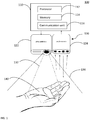
- Fig. 1 shows an example projection mapping system 100 with a single projection mapping unit 120.
- the projection mapping system 100 includes a controller 110 and a projection mapping unit 120.
- the projection mapping unit 120 includes a projector 122 and a camera 124.
- the projector 122 projects a light beam 132 into a projection mapping area 134 of the projection mapping unit (i.e. a field of illumination of the projector 122).
- the light beam is projected onto a projection surface 140 positioned in the projection mapping area 134 of the projection mapping unit 120.
- the light beam may be a beam for illumination purposes.
- the light beam may include information (e.g. image, graphics, texts, or the like).
- the light beam may be pixel-based or alphanumeric-based.
- the projection surface 140 may be a human body (e.g. a palm of a user as shown in Fig. 1 or any other human body parts), a piece of paper or a board held by a user, a wall or floor in a building or a vehicle, or any other objects or surfaces in any structure.
- the projector 122 projects a certain content onto a projection surface 140.
- the projected content may be an image of a user interface (i.e. a projected user interface) such that a user may interact with the system 100 via the projected user interface.
- the projected content may be a visual content, such as a movie, a visual sign, etc.
- the projector 122 includes a lighting unit for generating the light beam 132.
- the projector 122 can cause a change in distribution of the light, i.e. can steer the light beam 132 to a specific direction.
- the projector 122 may include a scanning illumination unit in which a light beam generated by a light source in the projector 122 is deflected in different directions at high speed by a scanning mirror.
- the light source may be one or more light emitting diodes (LEDs), laser diodes, or the like.
- the projector 122 may include a pixel-based lighting unit, for example a digital light processor (DLP) projector, a liquid crystal display (LCD) imager, or the like.
- DLP digital light processor
- LCD liquid crystal display
- the camera 124 is provided for object and/or gesture recognition.
- the camera 124 captures images in the field of view of the camera 124.
- the camera 124 may be a depth camera (3D camera) with depth sensing capabilities.
- the camera 124 may include a processing unit (not shown) which analyzes the captured images and then recognizes objects and/or gestures within the field of view of the camera 124.
- the projector 122 and the camera 124 are coupled to a controller 110 (a computer).
- the image or data captured by the camera 124 may be sent to the controller 110 and the controller 124 may analyze the captured images and recognize objects and/or gestures.
- the controller 110 may control the projector 122 to steer the light beam 134 such that the projected light beam 134 follows the moving object (i.e. the projected surface 140). This tracking can be automatically performed to ensure that the projected content is projected onto the projection surface 140 (e.g. the palm of the user as shown in Fig. 1 ) as the projection surface 140 moves around in the projection mapping area 134.
- the controller 110 may include, or alternatively be in communication with, a processor 112, a memory 114, and a communication unit 116.
- the processor 112 may be in communication with the memory 114 via a bus for passing information among components of the controller 110.
- the memory 114 may include, for example, one or more volatile and/or non-volatile memory modules.
- the memory 114 may be configured to store information, data, applications, instructions, or the like for enabling the controller 112 to carry out various functions in accordance with examples disclosed herein.
- the processor 112 is configured to execute instructions stored in the memory 114 for implementing the functionalities disclosed herein.
- the communication unit 116 is a device or circuitry configured to receive and/or transmit data from/to a network or other devices.
- the communication unit 116 may be implemented in hardware or a combination of hardware and software.
- the communication unit 116 may include devices or circuitries for wired and/or wireless communication.
- the communication unit 116 may include an antenna for wireless communication.
- the communication unit 116 may include a modem and/or other hardware/software for supporting communication via cable, digital subscriber line (DSL), universal serial bus (USB), or the like.
- the projection mapping unit 120 may project a user interface onto a projection surface 140 and may receive the user's input via the projected user interface.
- An image of a user interface may be projected onto a projection surface 140 (e.g. a user's body, a floor, a wall, a table).
- the projected user interface may include a keypad, a keyboard, graphical icons or buttons, or selectable menu items, or the like.
- the projection mapping unit 120 may project a user interface that simulates a touch screen display.
- the camera 124 captures the user's gesture and the processor 112 receives an indication of a user input associated with the projected touch screen display (i.e., the projected user interface).
- the controller 110 receives the user input and may respond or execute instructions in response to the user input.
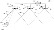
- Figs. 2-7 show a projection mapping system 200 configured to handover a projected content among a plurality of projection mapping units in accordance with one example.
- An example handover process is shown in Figs. 2-7 .
- the projection mapping system 200 may include a plurality of projection mapping units 120a-120c and a controller 110.
- the controller 110 is coupled to each of the plurality of projection mapping units 120a-120c.
- Figs. 2-7 show only three projection mapping units 120a-120c as an example, and any number of projection mapping units may be deployed.
- the projection mapping units may be arrayed in a specific pattern (linear or two-dimensional grid) or may be arranged without any specific pattern.
- Each projection mapping unit 120a-120c may include a projector 122 and a camera 124, as disclosed above with reference to Fig. 1 .
- Each projection mapping unit 120a-120c has a specific projection mapping area 134a-134c (i.e. a field of illumination/view).
- Each projection mapping unit 120a-120c is configured to project a content onto a projection surface 140 in a corresponding projection mapping area 134a-134c.
- the projection mapping unit 120a-120c may be a fixed unit (i.e. fixed in a specific location with a fixed projection mapping area).
- a projection mapping unit 120a-120c may be installed on a gimbal (or a similar device) such that the projection mapping unit 120a-120c may rotate or tilt to cover more than the field of illumination and view of the projector 122 and camera 124, i.e. the projection mapping unit 120a-120c may have a projection mapping area covering 360 degrees or any other angle (e.g. 270 or 180 degrees).
- the projection mapping areas of (two or more) neighboring projection mapping units 120a-120c in the system 200 may overlap each other.
- All projection mapping areas of the plurality of projection mapping units 120a-120c in the system 200 constitute a combined projection mapping area of the system 200.
- the projection mapping unit 120a-120c may project a content (e.g. an image of a user interface) onto a projection surface 140 (e.g. a palm of a user in this example).
- a content e.g. an image of a user interface
- the controller 110 may control the projector 122 to steer the projected light beam 132a-132c onto the moving projection surface 140.
- the movement of hand is tracked and the projected light beam 132a follows the movement of the user's palm so that the projected content is continuously displayed on the user's palm (i.e. the projection surface 140).
- the controller 110 may initiate and execute a process to handover the projected content from the projection mapping unit 120a to the projection mapping unit 120b.
- the handover may be triggered if the projected surface 140 crosses a certain threshold in the overlapping projection mapping area 152 between the projection mapping units 120a and 120b (e.g. if the projection surface 140 gets closer to the projection mapping unit 120b more than a certain degree).
- the projection mapping unit 120b Similar to the projection mapping unit 120a, the projection mapping unit 120b also tracks the movement of the projection surface 140 and steers the projected light beam 132b onto the moving projection surface as the projection surface 140 moves around, as shown in Fig. 5 . As the user further moves his/her hand to the right side, the projected content is handed over to the projection mapping unit 120c as shown in Fig. 6 .
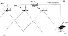
- the projected content may be handed over to a user equipment 160.
- the user equipment 160 may be a mobile phone, a smart phone, a tablet computer, a laptop computer, augmented reality (AR) glasses or any types of wearable devices, or the like.
- AR augmented reality
- the controller 110 has a communication unit 116 for wireless connection to the user equipment 160.
- the wireless connection may be established using any wireless communication protocol, such as IEEE 802.11 WLAN, Bluetooth, cellular communication protocol such as Third Generation (3G), Fourth Generation (4G), or Fifth Generation (5G), etc.
- the controller 110 establishes a wireless connection to the user equipment 160 and hands over the projected content to the user equipment 160.
- the user equipment 160 may display the same projected content on its display.
- the actual displayed image on the user equipment 160 may be different from the image of the projected content even though the underlying contents are the same.
- the handover may be performed within a certain application.
- the content (the projected content) may be visible on the user equipment when the application is running.
- a notification may be sent to the user to indicate that the application is now available on the user equipment because the user is leaving the projection mapping area and the user may use the user equipment to run, view, or use the application in response to the notification.
- the controller 110 may be configured to handover contents displayed on a display of the user equipment 160 to one of the projection mapping units 120a-120c when a user enters a combined projection mapping area of the plurality of projection mapping units 120a-120c.
- the content displayed on the user device may be handed over from the user equipment 160 to one of the projection mapping units 120a-120c in the system 200.
- the localization of the user equipment 160 relative to the projection mapping area may be determined by using, for example, radio-based tracking (e.g. ultra-wideband (UWB) positioning, Bluetooth, or similar) or optical tracking (e.g. the projection mapping system).
- radio-based tracking e.g. ultra-wideband (UWB) positioning, Bluetooth, or similar
- optical tracking e.g. the projection mapping system
- the user may be notified that his/her content on the user equipment is now available anywhere in the room/space.
- the projection mapping may be initiated by the system as soon as the user enters the projection mapping area or with a specific gesture from the user (e.g. opening a hand and showing a palm, or tap a wall, or the like).
- the projection mapping system 200 may be installed in a vehicle, in a building (e.g. in offices, living room, restaurants, cafes, etc.), or in any place.
- Fig. 8 shows, as an example, a vehicle cabin with the projection mapping system 200 installed in a ceiling of the vehicle cabin.
- the projection mapping system 200 installed in the ceiling of the vehicle cabin may cover the front and rear rows of the seats and provide a projected user interface to the driver and to the passenger.
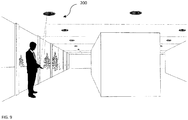
- the projection mapping system may be installed in a building, as illustrated in Fig. 9 .
- the projected mapping system 200 may be installed in a ceiling (or any other place such as a wall, furniture, etc.) inside a building and may project a content (e.g. a user interface) on a projection surface (e.g. a user's body part or any object held by a user, on a floor or wall of the building).
- a content e.g. a user interface
- a projection surface e.g. a user's body part or any object held by a user, on a floor or wall of the building.
- the system 200 detects the entrance of the user and activates one of the projection mapping units in the system for the user.
- the projected content may be handed over between the projection mapping units as disclosed above.
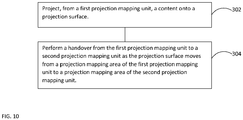
- Fig. 10 is a flow diagram of an example method for projected content handover among a plurality of projection mapping units.
- Each projection mapping unit has a specific projection mapping area and projection mapping areas of two or more neighboring projection mapping units overlap each other.
- a content is projected onto a projection surface from a first projection mapping unit.
- the projected content is steered as the projection surface moves around.
- a handover is performed from the first projection mapping unit to a second projection mapping unit as the projection surface moves from a projection mapping area of the first projection mapping unit to a projection mapping area of the second projection mapping unit.
- a wireless connection may be established to a user equipment, and a handover of the projected content may be performed to the user equipment if the projected surface moves out of a combined projection mapping area of the plurality of projection mapping units.
- a handover of a content on the user equipment may be performed to one of the projection mapping units if the user equipment enters the combined projection mapping area of the plurality of projection mapping units.
- the user equipment may be one of a mobile phone, a smart phone, a tablet computer, a laptop computer, or augmented reality (AR) glasses.
- AR augmented reality
- Another example is a computer program having a program code for performing at least one of the methods described herein, when the computer program is executed on a computer, a processor, or a programmable hardware component.
- Another example is a machine-readable storage including machine readable instructions, when executed, to implement a method or realize an apparatus as described herein.
- a further example is a machine-readable medium including code, when executed, to cause a machine to perform any of the methods described herein.
- Examples may further be or relate to a computer program having a program code for performing one or more of the above methods, when the computer program is executed on a computer or processor. Steps, operations or processes of various above-described methods may be performed by programmed computers or processors. Examples may also cover program storage devices such as digital data storage media, which are machine, processor or computer readable and encode machine-executable, processor-executable or computer-executable programs of instructions. The instructions perform or cause performing some or all of the acts of the above-described methods.
- the program storage devices may comprise or be, for instance, digital memories, magnetic storage media such as magnetic disks and magnetic tapes, hard drives, or optically readable digital data storage media.
- FIG. 1 may also cover computers, processors or control units programmed to perform the acts of the above-described methods or (field) programmable logic arrays ((F)PLAs) or (field) programmable gate arrays ((F)PGAs), programmed to perform the acts of the above-described methods.
- a functional block denoted as "means for " performing a certain function may refer to a circuit that is configured to perform a certain function.
- a "means for s.th.” may be implemented as a "means configured to or suited for s.th.”, such as a device or a circuit configured to or suited for the respective task.
- Functions of various elements shown in the figures may be implemented in the form of dedicated hardware, such as “a signal provider”, “a signal processing unit”, “a processor”, “a controller”, etc. as well as hardware capable of executing software in association with appropriate software.
- a processor the functions may be provided by a single dedicated processor, by a single shared processor, or by a plurality of individual processors, some of which or all of which may be shared.
- processor or “controller” is by far not limited to hardware exclusively capable of executing software but may include digital signal processor (DSP) hardware, network processor, application specific integrated circuit (ASIC), field programmable gate array (FPGA), read only memory (ROM) for storing software, random access memory (RAM), and non-volatile storage.
- DSP digital signal processor
- ASIC application specific integrated circuit
- FPGA field programmable gate array
- ROM read only memory
- RAM random access memory
- non-volatile storage Other hardware, conventional and/or custom, may also be included.
- a block diagram may, for instance, illustrate a high-level circuit diagram implementing the principles of the disclosure.
- a flow chart, a flow diagram, a state transition diagram, a pseudo code, and the like may represent various processes, operations or steps, which may, for instance, be substantially represented in computer readable medium and so executed by a computer or processor, whether or not such computer or processor is explicitly shown.
- Methods disclosed in the specification or in the claims may be implemented by a device having means for performing each of the respective acts of these methods.
- each claim may stand on its own as a separate example. While each claim may stand on its own as a separate example, it is to be noted that - although a dependent claim may refer in the claims to a specific combination with one or more other claims - other examples may also include a combination of the dependent claim with the subject matter of each other dependent or independent claim. Such combinations are explicitly proposed herein unless it is stated that a specific combination is not intended. Furthermore, it is intended to include also features of a claim to any other independent claim even if this claim is not directly made dependent to the independent claim.
Landscapes
- Engineering & Computer Science (AREA)
- Multimedia (AREA)
- Signal Processing (AREA)
- Controls And Circuits For Display Device (AREA)
- User Interface Of Digital Computer (AREA)
Abstract
Description
- Examples relate to projection mapping, more particularly a method and system for projected content handover among a plurality of projection mapping units.
- Projection mapping uses technology to project objects onto a surface. Using projection mapping, objects can be transformed into a display surface for video projection. The objects onto which the images are projected may not necessarily be a flat surface but any shapes of objects. A projection-based user interface may allow users to remotely control devices through the movement of fingertips over a projected surface, thereby offering a more natural and intuitive way of user interaction.
- Examples are disclosed for a system for projected content handover. The projection mapping system may include a plurality of projection mapping units and a controller. Each projection mapping unit has a specific projection mapping area and is configured to project a content onto a projection surface in a corresponding projection mapping area. Projection mapping areas of two or more neighboring projection mapping units overlap each other. The controller is coupled to each of the plurality of projection mapping units. The controller may be configured to control each projection mapping unit to steer the projected content (e.g. projected user interface) as the projection surface moves around. The controller may handover the projected content from a first projection mapping unit to a second projection mapping unit as the projection surface moves from a projection mapping area of the first projection mapping unit to a projection mapping area of the second projection mapping unit. With this scheme, a user may continuously use the projected content without interruption while moving around the area.
- In some examples, the controller may include a communication unit to connect to a user equipment wirelessly. The controller may be configured to handover the projected content to the user equipment if the projected surface moves out of a combined projection mapping area of the plurality of projection mapping units. The user equipment may be one of a mobile phone, a smart phone, a tablet computer, a laptop computer, or augmented reality (AR) glasses, etc. After the handover to the user equipment, the same content may be displayed on the user equipment.
- In another example, when a user who is out of a combined projection mapping area of the system enters the combined projection mapping area while using the user equipment, the controller may handover contents displayed on a display of the user equipment to one of the projection mapping units.
- At least one of the plurality of projection mapping units is installed on a gimbal such that the projection mapping unit may rotate or tile to cover a wider area. The projection mapping system may be installed in a vehicle cabin, in a building, or in any other places. The projected content may be projected on one of a human body part, a floor or wall of a building, or an object held by a user.
- In accordance with other examples, a method for projected content handover among a plurality of projection mapping units is disclosed. Each projection mapping unit has a specific projection mapping area and projection mapping areas of two or more neighboring projection mapping units overlap each other. A content may be projected from a first projection mapping unit onto a projection surface. The projected content is steered as the projection surface moves around. A handover may be performed from the first projection mapping unit to a second projection mapping unit if the projection surface moves from a projection mapping area of the first projection mapping unit to a projection mapping area of the second projection mapping unit.
- In accordance with some examples, a wireless connection may be established to a user equipment and a handover of the projected content may be performed to the user equipment if the projected surface moves out of a combined projection mapping area of the plurality of projection mapping units. The user equipment may be one of a mobile phone, a smart phone, a tablet computer, a laptop computer, or AR glasses, etc.
- In other examples, when a user enters a combined projection mapping area of the plurality of projection mapping units while using a user equipment, the content on the user equipment may be handed over to one of the projection mapping units.
- Some examples of apparatuses and/or methods will be described in the following by way of example only, and with reference to the accompanying figures, in which
-
Fig. 1 shows an example projection mapping system with a single projection mapping unit; -
Figs. 2-7 show a projection mapping system configured to handover a projected content among projection mapping units in accordance with one example; -
Fig. 8 shows a projection mapping system installed in a vehicle in accordance with one example; -
Fig. 9 shows a projection mapping system installed in a building in accordance with one example; and -
Fig. 10 is a flow diagram of an example method for projected content handover among a plurality of projection mapping units. - Various examples will now be described more fully with reference to the accompanying drawings in which some examples are illustrated. In the figures, the thicknesses of lines, layers and/or regions may be exaggerated for clarity.
- Accordingly, while further examples are capable of various modifications and alternative forms, some particular examples thereof are shown in the figures and will subsequently be described in detail. However, this detailed description does not limit further examples to the particular forms described. Further examples may cover all modifications, equivalents, and alternatives falling within the scope of the disclosure. Like numbers refer to like or similar elements throughout the description of the figures, which may be implemented identically or in modified form when compared to one another while providing for the same or a similar functionality.
- It will be understood that when an element is referred to as being "connected" or "coupled" to another element, the elements may be directly connected or coupled or via one or more intervening elements. If two elements A and B are combined using an "or", this is to be understood to disclose all possible combinations, i.e. only A, only B as well as A and B. An alternative wording for the same combinations is "at least one of A and B". The same applies for combinations of more than 2 elements.
- The terminology used herein for the purpose of describing particular examples is not intended to be limiting for further examples. Whenever a singular form such as "a," "an" and "the" is used and using only a single element is neither explicitly or implicitly defined as being mandatory, further examples may also use plural elements to implement the same functionality. Likewise, when a functionality is subsequently described as being implemented using multiple elements, further examples may implement the same functionality using a single element or processing entity. It will be further understood that the terms "comprises," "comprising," "includes" and/or "including," when used, specify the presence of the stated features, integers, steps, operations, processes, acts, elements and/or components, but do not preclude the presence or addition of one or more other features, integers, steps, operations, processes, acts, elements, components and/or any group thereof.
- Unless otherwise defined, all terms (including technical and scientific terms) are used herein in their ordinary meaning of the art to which the examples belong.
- In accordance with examples disclosed herein, a plurality of projection mapping units are deployed in a vehicle cabin, in a building, or in any other places, and a projected content (e.g. a projected user interface) may be handed over among the projection mapping units such that a user may be able to use the projected content while moving around the area without interruption.
-
Fig. 1 shows an exampleprojection mapping system 100 with a singleprojection mapping unit 120. Theprojection mapping system 100 includes acontroller 110 and aprojection mapping unit 120. Theprojection mapping unit 120 includes aprojector 122 and acamera 124. - The
projector 122 projects alight beam 132 into aprojection mapping area 134 of the projection mapping unit (i.e. a field of illumination of the projector 122). The light beam is projected onto aprojection surface 140 positioned in theprojection mapping area 134 of theprojection mapping unit 120. The light beam may be a beam for illumination purposes. Alternatively, the light beam may include information (e.g. image, graphics, texts, or the like). The light beam may be pixel-based or alphanumeric-based. Theprojection surface 140 may be a human body (e.g. a palm of a user as shown inFig. 1 or any other human body parts), a piece of paper or a board held by a user, a wall or floor in a building or a vehicle, or any other objects or surfaces in any structure. - The
projector 122 projects a certain content onto aprojection surface 140. In one example, the projected content may be an image of a user interface (i.e. a projected user interface) such that a user may interact with thesystem 100 via the projected user interface. In another example, the projected content may be a visual content, such as a movie, a visual sign, etc. - The
projector 122 includes a lighting unit for generating thelight beam 132. Theprojector 122 can cause a change in distribution of the light, i.e. can steer thelight beam 132 to a specific direction. For example, theprojector 122 may include a scanning illumination unit in which a light beam generated by a light source in theprojector 122 is deflected in different directions at high speed by a scanning mirror. The light source may be one or more light emitting diodes (LEDs), laser diodes, or the like. Alternatively, theprojector 122 may include a pixel-based lighting unit, for example a digital light processor (DLP) projector, a liquid crystal display (LCD) imager, or the like. - The
camera 124 is provided for object and/or gesture recognition. Thecamera 124 captures images in the field of view of thecamera 124. Thecamera 124 may be a depth camera (3D camera) with depth sensing capabilities. Thecamera 124 may include a processing unit (not shown) which analyzes the captured images and then recognizes objects and/or gestures within the field of view of thecamera 124. - The
projector 122 and thecamera 124 are coupled to a controller 110 (a computer). The image or data captured by thecamera 124 may be sent to thecontroller 110 and thecontroller 124 may analyze the captured images and recognize objects and/or gestures. As the camera 124 (or alternatively the controller 110) detects a movement of an object in the field of view of thecamera 124, thecontroller 110 may control theprojector 122 to steer thelight beam 134 such that the projectedlight beam 134 follows the moving object (i.e. the projected surface 140). This tracking can be automatically performed to ensure that the projected content is projected onto the projection surface 140 (e.g. the palm of the user as shown inFig. 1 ) as theprojection surface 140 moves around in theprojection mapping area 134. - The
controller 110 may include, or alternatively be in communication with, aprocessor 112, amemory 114, and acommunication unit 116. Theprocessor 112 may be in communication with thememory 114 via a bus for passing information among components of thecontroller 110. Thememory 114 may include, for example, one or more volatile and/or non-volatile memory modules. Thememory 114 may be configured to store information, data, applications, instructions, or the like for enabling thecontroller 112 to carry out various functions in accordance with examples disclosed herein. Theprocessor 112 is configured to execute instructions stored in thememory 114 for implementing the functionalities disclosed herein. - The
communication unit 116 is a device or circuitry configured to receive and/or transmit data from/to a network or other devices. Thecommunication unit 116 may be implemented in hardware or a combination of hardware and software. Thecommunication unit 116 may include devices or circuitries for wired and/or wireless communication. Thecommunication unit 116 may include an antenna for wireless communication. Thecommunication unit 116 may include a modem and/or other hardware/software for supporting communication via cable, digital subscriber line (DSL), universal serial bus (USB), or the like. - The
projection mapping unit 120 may project a user interface onto aprojection surface 140 and may receive the user's input via the projected user interface. An image of a user interface may be projected onto a projection surface 140 (e.g. a user's body, a floor, a wall, a table). The projected user interface may include a keypad, a keyboard, graphical icons or buttons, or selectable menu items, or the like. Theprojection mapping unit 120 may project a user interface that simulates a touch screen display. Thecamera 124 captures the user's gesture and theprocessor 112 receives an indication of a user input associated with the projected touch screen display (i.e., the projected user interface). Thecontroller 110 receives the user input and may respond or execute instructions in response to the user input. -
Figs. 2-7 show aprojection mapping system 200 configured to handover a projected content among a plurality of projection mapping units in accordance with one example. An example handover process is shown inFigs. 2-7 . Theprojection mapping system 200 may include a plurality ofprojection mapping units 120a-120c and acontroller 110. Thecontroller 110 is coupled to each of the plurality ofprojection mapping units 120a-120c. It should be noted thatFigs. 2-7 show only threeprojection mapping units 120a-120c as an example, and any number of projection mapping units may be deployed. The projection mapping units may be arrayed in a specific pattern (linear or two-dimensional grid) or may be arranged without any specific pattern. - Each
projection mapping unit 120a-120c may include aprojector 122 and acamera 124, as disclosed above with reference toFig. 1 . Eachprojection mapping unit 120a-120c has a specificprojection mapping area 134a-134c (i.e. a field of illumination/view). Eachprojection mapping unit 120a-120c is configured to project a content onto aprojection surface 140 in a correspondingprojection mapping area 134a-134c. Theprojection mapping unit 120a-120c may be a fixed unit (i.e. fixed in a specific location with a fixed projection mapping area). Alternatively, or additionally, aprojection mapping unit 120a-120c may be installed on a gimbal (or a similar device) such that theprojection mapping unit 120a-120c may rotate or tilt to cover more than the field of illumination and view of theprojector 122 andcamera 124, i.e. theprojection mapping unit 120a-120c may have a projection mapping area covering 360 degrees or any other angle (e.g. 270 or 180 degrees). - The projection mapping areas of (two or more) neighboring
projection mapping units 120a-120c in thesystem 200 may overlap each other. For example, as shown inFig. 2 , theprojection mapping areas projection mapping units projection mapping areas projection mapping units projection mapping units 120a-120c in thesystem 200 constitute a combined projection mapping area of thesystem 200. - The
projection mapping unit 120a-120c may project a content (e.g. an image of a user interface) onto a projection surface 140 (e.g. a palm of a user in this example). As theprojection surface 140 moves around (e.g. as the user moves his/her hand around), the movement is detected through thecamera 124 and thecontroller 110 may control theprojector 122 to steer the projectedlight beam 132a-132c onto the movingprojection surface 140. As shown inFig. 3 , as the user moves his/her hand to the right side, the movement of hand is tracked and the projectedlight beam 132a follows the movement of the user's palm so that the projected content is continuously displayed on the user's palm (i.e. the projection surface 140). - As shown in
Fig. 4 , as the user moves his/her hand toward theprojection mapping unit 120b and theprojection surface 140 moves into an overlappingprojection mapping area 152 of theprojection mapping units controller 110 may initiate and execute a process to handover the projected content from theprojection mapping unit 120a to theprojection mapping unit 120b. The handover may be triggered if the projectedsurface 140 crosses a certain threshold in the overlappingprojection mapping area 152 between theprojection mapping units projection surface 140 gets closer to theprojection mapping unit 120b more than a certain degree). - Similar to the
projection mapping unit 120a, theprojection mapping unit 120b also tracks the movement of theprojection surface 140 and steers the projectedlight beam 132b onto the moving projection surface as theprojection surface 140 moves around, as shown inFig. 5 . As the user further moves his/her hand to the right side, the projected content is handed over to theprojection mapping unit 120c as shown inFig. 6 . - If the
projection surface 140 moves out of coverage of anyprojection mapping units 120a-120c (i.e. out of a combine mapping area of the system) as shown inFig. 7 , the projected content may be handed over to auser equipment 160. Theuser equipment 160 may be a mobile phone, a smart phone, a tablet computer, a laptop computer, augmented reality (AR) glasses or any types of wearable devices, or the like. - The
controller 110 has acommunication unit 116 for wireless connection to theuser equipment 160. The wireless connection may be established using any wireless communication protocol, such as IEEE 802.11 WLAN, Bluetooth, cellular communication protocol such as Third Generation (3G), Fourth Generation (4G), or Fifth Generation (5G), etc. As theprojection surface 140 moves out of the combined projection mapping area of thesystem 200, thecontroller 110 establishes a wireless connection to theuser equipment 160 and hands over the projected content to theuser equipment 160. After the handover, theuser equipment 160 may display the same projected content on its display. The actual displayed image on theuser equipment 160 may be different from the image of the projected content even though the underlying contents are the same. The handover may be performed within a certain application. The content (the projected content) may be visible on the user equipment when the application is running. Alternatively, a notification may be sent to the user to indicate that the application is now available on the user equipment because the user is leaving the projection mapping area and the user may use the user equipment to run, view, or use the application in response to the notification. - Additionally, the
controller 110 may be configured to handover contents displayed on a display of theuser equipment 160 to one of theprojection mapping units 120a-120c when a user enters a combined projection mapping area of the plurality ofprojection mapping units 120a-120c. When a user enters a combined projection area of thesystem 200 while using his/her user equipment 160 (e.g. a device with a screen), the content displayed on the user device may be handed over from theuser equipment 160 to one of theprojection mapping units 120a-120c in thesystem 200. The localization of theuser equipment 160 relative to the projection mapping area may be determined by using, for example, radio-based tracking (e.g. ultra-wideband (UWB) positioning, Bluetooth, or similar) or optical tracking (e.g. the projection mapping system). The user may be notified that his/her content on the user equipment is now available anywhere in the room/space. The projection mapping may be initiated by the system as soon as the user enters the projection mapping area or with a specific gesture from the user (e.g. opening a hand and showing a palm, or tap a wall, or the like). - The
projection mapping system 200 may be installed in a vehicle, in a building (e.g. in offices, living room, restaurants, cafes, etc.), or in any place.Fig. 8 shows, as an example, a vehicle cabin with theprojection mapping system 200 installed in a ceiling of the vehicle cabin. For example, theprojection mapping system 200 installed in the ceiling of the vehicle cabin may cover the front and rear rows of the seats and provide a projected user interface to the driver and to the passenger. - In another example, the projection mapping system may be installed in a building, as illustrated in
Fig. 9 . The projectedmapping system 200 may be installed in a ceiling (or any other place such as a wall, furniture, etc.) inside a building and may project a content (e.g. a user interface) on a projection surface (e.g. a user's body part or any object held by a user, on a floor or wall of the building). As a user enters a building (i.e. a combined projection mapping area of thesystem 200 installed in the building), thesystem 200 detects the entrance of the user and activates one of the projection mapping units in the system for the user. As the user moves around in the building, the projected content may be handed over between the projection mapping units as disclosed above. -
Fig. 10 is a flow diagram of an example method for projected content handover among a plurality of projection mapping units. Each projection mapping unit has a specific projection mapping area and projection mapping areas of two or more neighboring projection mapping units overlap each other. Atstep 302, a content is projected onto a projection surface from a first projection mapping unit. The projected content is steered as the projection surface moves around. Atstep 304, a handover is performed from the first projection mapping unit to a second projection mapping unit as the projection surface moves from a projection mapping area of the first projection mapping unit to a projection mapping area of the second projection mapping unit. - In some examples, a wireless connection may be established to a user equipment, and a handover of the projected content may be performed to the user equipment if the projected surface moves out of a combined projection mapping area of the plurality of projection mapping units. In other examples, a handover of a content on the user equipment may be performed to one of the projection mapping units if the user equipment enters the combined projection mapping area of the plurality of projection mapping units. The user equipment may be one of a mobile phone, a smart phone, a tablet computer, a laptop computer, or augmented reality (AR) glasses.
- Another example is a computer program having a program code for performing at least one of the methods described herein, when the computer program is executed on a computer, a processor, or a programmable hardware component. Another example is a machine-readable storage including machine readable instructions, when executed, to implement a method or realize an apparatus as described herein. A further example is a machine-readable medium including code, when executed, to cause a machine to perform any of the methods described herein.
- The aspects and features mentioned and described together with one or more of the previously detailed examples and figures, may as well be combined with one or more of the other examples in order to replace a like feature of the other example or in order to additionally introduce the feature to the other example.
- Examples may further be or relate to a computer program having a program code for performing one or more of the above methods, when the computer program is executed on a computer or processor. Steps, operations or processes of various above-described methods may be performed by programmed computers or processors. Examples may also cover program storage devices such as digital data storage media, which are machine, processor or computer readable and encode machine-executable, processor-executable or computer-executable programs of instructions. The instructions perform or cause performing some or all of the acts of the above-described methods. The program storage devices may comprise or be, for instance, digital memories, magnetic storage media such as magnetic disks and magnetic tapes, hard drives, or optically readable digital data storage media. Further examples may also cover computers, processors or control units programmed to perform the acts of the above-described methods or (field) programmable logic arrays ((F)PLAs) or (field) programmable gate arrays ((F)PGAs), programmed to perform the acts of the above-described methods.
- The description and drawings merely illustrate the principles of the disclosure. Furthermore, all examples recited herein are principally intended expressly to be only for pedagogical purposes to aid the reader in understanding the principles of the disclosure and the concepts contributed by the inventor(s) to furthering the art. All statements herein reciting principles, aspects, and examples of the disclosure, as well as specific examples thereof, are intended to encompass equivalents thereof.
- A functional block denoted as "means for ..." performing a certain function may refer to a circuit that is configured to perform a certain function. Hence, a "means for s.th." may be implemented as a "means configured to or suited for s.th.", such as a device or a circuit configured to or suited for the respective task.
- Functions of various elements shown in the figures, including any functional blocks labeled as "means", "means for providing a sensor signal", "means for generating a transmit signal.", etc., may be implemented in the form of dedicated hardware, such as "a signal provider", "a signal processing unit", "a processor", "a controller", etc. as well as hardware capable of executing software in association with appropriate software. When provided by a processor, the functions may be provided by a single dedicated processor, by a single shared processor, or by a plurality of individual processors, some of which or all of which may be shared. However, the term "processor" or "controller" is by far not limited to hardware exclusively capable of executing software but may include digital signal processor (DSP) hardware, network processor, application specific integrated circuit (ASIC), field programmable gate array (FPGA), read only memory (ROM) for storing software, random access memory (RAM), and non-volatile storage. Other hardware, conventional and/or custom, may also be included.
- A block diagram may, for instance, illustrate a high-level circuit diagram implementing the principles of the disclosure. Similarly, a flow chart, a flow diagram, a state transition diagram, a pseudo code, and the like may represent various processes, operations or steps, which may, for instance, be substantially represented in computer readable medium and so executed by a computer or processor, whether or not such computer or processor is explicitly shown. Methods disclosed in the specification or in the claims may be implemented by a device having means for performing each of the respective acts of these methods.
- It is to be understood that the disclosure of multiple acts, processes, operations, steps or functions disclosed in the specification or claims may not be construed as to be within the specific order, unless explicitly or implicitly stated otherwise, for instance for technical reasons. Therefore, the disclosure of multiple acts or functions will not limit these to a particular order unless such acts or functions are not interchangeable for technical reasons. Furthermore, in some examples a single act, function, process, operation or step may include or may be broken into multiple sub-acts, -functions, -processes, -operations or -steps, respectively. Such sub acts may be included and part of the disclosure of this single act unless explicitly excluded.
- Furthermore, the following claims are hereby incorporated into the detailed description, where each claim may stand on its own as a separate example. While each claim may stand on its own as a separate example, it is to be noted that - although a dependent claim may refer in the claims to a specific combination with one or more other claims - other examples may also include a combination of the dependent claim with the subject matter of each other dependent or independent claim. Such combinations are explicitly proposed herein unless it is stated that a specific combination is not intended. Furthermore, it is intended to include also features of a claim to any other independent claim even if this claim is not directly made dependent to the independent claim.
Claims (17)
- A system for projected content handover, comprising:a plurality of projection mapping units, wherein each projection mapping unit has a specific projection mapping area and is configured to project a content onto a projection surface in a corresponding projection mapping area, wherein projection mapping areas of two or more neighboring projection mapping units overlap each other; anda controller coupled to each of the plurality of projection mapping units and configured to handover the projected content from a first projection mapping unit to a second projection mapping unit as the projection surface moves from a projection mapping area of the first projection mapping unit to a projection mapping area of the second projection mapping unit.
- The system of claim 1, wherein the controller includes a communication unit to connect to a user equipment wirelessly, and the controller is configured to handover the projected content to the user equipment as the projected surface moves out of a combined projection mapping area of the plurality of projection mapping units.
- The system of claim 2, wherein the controller is configured to handover contents displayed on a display of the user equipment to one of the projection mapping units as the user equipment enters a combined projection mapping area of the plurality of projection mapping units.
- The system of claim 2, wherein the user equipment is one of a mobile phone, a smart phone, a tablet computer, a laptop computer, or augmented reality (AR) glasses.
- The system of claim 1, wherein at least one of the plurality of projection mapping units is installed on a gimbal.
- The system of claim 1, wherein the system is installed in a vehicle cabin.
- The system of claim 1, wherein the system is installed in a building.
- The system of claim 1, wherein the projected content is projected on one of a human body part, a floor or wall of a building, or an object held by a user.
- A method for projected content handover among a plurality of projection mapping units, wherein each projection mapping unit has a specific projection mapping area and projection mapping areas of two or more neighboring projection mapping units overlap each other, the method comprising:projecting, from a first projection mapping unit, a content onto a projection surface; andperforming a handover from the first projection mapping unit to a second projection mapping unit as the projection surface moves from a projection mapping area of the first projection mapping unit to a projection mapping area of the second projection mapping unit.
- The method of claim 9, further comprising:establishing a wireless connection to a user equipment; andperforming a handover of the projected content to the user equipment if the projected surface moves out of a combined projection mapping area of the plurality of projection mapping units.
- The method of claim 10, further comprising:
performing a handover of a content on the user equipment to one of the projection mapping units if the user equipment enters the combined projection mapping area of the plurality of projection mapping units. - The method of claim 10, wherein the user equipment is one of a mobile phone, a smart phone, a tablet computer, a laptop computer, or augmented reality (AR) glasses.
- The method of claim 9, wherein at least one of the plurality of projection mapping units is installed on a gimbal.
- The method of claim 9, wherein the projection mapping units are installed in a vehicle cabin.
- The method of claim 9, wherein the projection mapping units are installed in a building.
- The method of claim 9, wherein the projected content is projected on one of a human body part, a floor or wall of a building, or an object held by a user.
- A non-transitory machine-readable storage medium including code, when executed, to cause a machine to perform a method of claim 9.
Priority Applications (1)
| Application Number | Priority Date | Filing Date | Title |
|---|---|---|---|
| EP20163088.6A EP3879822A1 (en) | 2020-03-13 | 2020-03-13 | Method and system for projected content handover among a plurality of projection mapping units |
Applications Claiming Priority (1)
| Application Number | Priority Date | Filing Date | Title |
|---|---|---|---|
| EP20163088.6A EP3879822A1 (en) | 2020-03-13 | 2020-03-13 | Method and system for projected content handover among a plurality of projection mapping units |
Publications (1)
| Publication Number | Publication Date |
|---|---|
| EP3879822A1 true EP3879822A1 (en) | 2021-09-15 |
Family
ID=69844548
Family Applications (1)
| Application Number | Title | Priority Date | Filing Date |
|---|---|---|---|
| EP20163088.6A Pending EP3879822A1 (en) | 2020-03-13 | 2020-03-13 | Method and system for projected content handover among a plurality of projection mapping units |
Country Status (1)
| Country | Link |
|---|---|
| EP (1) | EP3879822A1 (en) |
Citations (3)
| Publication number | Priority date | Publication date | Assignee | Title |
|---|---|---|---|---|
| US9129375B1 (en) * | 2012-04-25 | 2015-09-08 | Rawles Llc | Pose detection |
| US9870056B1 (en) * | 2012-10-08 | 2018-01-16 | Amazon Technologies, Inc. | Hand and hand pose detection |
| US20190121522A1 (en) * | 2017-10-21 | 2019-04-25 | EyeCam Inc. | Adaptive graphic user interfacing system |
-
2020
- 2020-03-13 EP EP20163088.6A patent/EP3879822A1/en active Pending
Patent Citations (3)
| Publication number | Priority date | Publication date | Assignee | Title |
|---|---|---|---|---|
| US9129375B1 (en) * | 2012-04-25 | 2015-09-08 | Rawles Llc | Pose detection |
| US9870056B1 (en) * | 2012-10-08 | 2018-01-16 | Amazon Technologies, Inc. | Hand and hand pose detection |
| US20190121522A1 (en) * | 2017-10-21 | 2019-04-25 | EyeCam Inc. | Adaptive graphic user interfacing system |
Similar Documents
| Publication | Publication Date | Title |
|---|---|---|
| US11868543B1 (en) | Gesture keyboard method and apparatus | |
| US12353646B2 (en) | Augmented reality eyewear 3D painting | |
| US12249036B2 (en) | Augmented reality eyewear with speech bubbles and translation | |
| US10528154B2 (en) | System for projecting content to a display surface having user-controlled size, shape and location/direction and apparatus and methods useful in conjunction therewith | |
| Rädle et al. | Huddlelamp: Spatially-aware mobile displays for ad-hoc around-the-table collaboration | |
| US9880619B2 (en) | Virtual reality system with a finger-wearable control | |
| KR101795644B1 (en) | Projection capture system, programming and method | |
| US8818027B2 (en) | Computing device interface | |
| US20130135199A1 (en) | System and method for user interaction with projected content | |
| US20140101578A1 (en) | Multi display device and control method thereof | |
| CN103207668A (en) | Information processing device, information processing method and computer program | |
| CN104025004A (en) | Information processing apparatus, information processing method, and computer program | |
| US20150193000A1 (en) | Image-based interactive device and implementing method thereof | |
| WO2016021022A1 (en) | Projection image display device and method for controlling same | |
| AU2011219427B2 (en) | A system for projecting content to a display surface having user-controlled size, shape and location/direction and apparatus and methods useful in conjunction therewith | |
| US10506290B2 (en) | Image information projection device and projection device control method | |
| US11221760B2 (en) | Information processing apparatus, information processing method, and storage medium | |
| Pinhanez | Augmenting reality with projected interactive displays | |
| EP3879822A1 (en) | Method and system for projected content handover among a plurality of projection mapping units | |
| TWM485448U (en) | Image-based virtual interaction device | |
| Rusňák et al. | Toward natural multi-user interaction in advanced collaborative display environments | |
| EP4400942A1 (en) | Touchless user interface control method, system, computer program and computer-readable medium | |
| EP4400944A1 (en) | Touchless user interface control method, system, computer program and computer-readable medium, based on a mobile device | |
| Cotting et al. | Interactive visual workspaces with dynamic foveal areas and adaptive composite interfaces | |
| Conotter et al. | Multi-device Interaction for Content Sharing |
Legal Events
| Date | Code | Title | Description |
|---|---|---|---|
| PUAI | Public reference made under article 153(3) epc to a published international application that has entered the european phase |
Free format text: ORIGINAL CODE: 0009012 |
|
| STAA | Information on the status of an ep patent application or granted ep patent |
Free format text: STATUS: THE APPLICATION HAS BEEN PUBLISHED |
|
| AK | Designated contracting states |
Kind code of ref document: A1 Designated state(s): AL AT BE BG CH CY CZ DE DK EE ES FI FR GB GR HR HU IE IS IT LI LT LU LV MC MK MT NL NO PL PT RO RS SE SI SK SM TR |
|
| STAA | Information on the status of an ep patent application or granted ep patent |
Free format text: STATUS: REQUEST FOR EXAMINATION WAS MADE |
|
| 17P | Request for examination filed |
Effective date: 20220112 |
|
| RBV | Designated contracting states (corrected) |
Designated state(s): AL AT BE BG CH CY CZ DE DK EE ES FI FR GB GR HR HU IE IS IT LI LT LU LV MC MK MT NL NO PL PT RO RS SE SI SK SM TR |
|
| STAA | Information on the status of an ep patent application or granted ep patent |
Free format text: STATUS: EXAMINATION IS IN PROGRESS |
|
| 17Q | First examination report despatched |
Effective date: 20230221 |
|
| P01 | Opt-out of the competence of the unified patent court (upc) registered |
Effective date: 20230502 |