EP3879676B1 - Fan motor and home appliance including same - Google Patents
Fan motor and home appliance including same Download PDFInfo
- Publication number
- EP3879676B1 EP3879676B1 EP21155125.4A EP21155125A EP3879676B1 EP 3879676 B1 EP3879676 B1 EP 3879676B1 EP 21155125 A EP21155125 A EP 21155125A EP 3879676 B1 EP3879676 B1 EP 3879676B1
- Authority
- EP
- European Patent Office
- Prior art keywords
- coil
- neutral point
- phase
- wound around
- motor
- Prior art date
- Legal status (The legal status is an assumption and is not a legal conclusion. Google has not performed a legal analysis and makes no representation as to the accuracy of the status listed.)
- Active
Links
Images







Classifications
-
- H—ELECTRICITY
- H02—GENERATION; CONVERSION OR DISTRIBUTION OF ELECTRIC POWER
- H02K—DYNAMO-ELECTRIC MACHINES
- H02K19/00—Synchronous motors or generators
- H02K19/02—Synchronous motors
- H02K19/10—Synchronous motors for multi-phase current
-
- H—ELECTRICITY
- H02—GENERATION; CONVERSION OR DISTRIBUTION OF ELECTRIC POWER
- H02K—DYNAMO-ELECTRIC MACHINES
- H02K1/00—Details of the magnetic circuit
- H02K1/06—Details of the magnetic circuit characterised by the shape, form or construction
- H02K1/12—Stationary parts of the magnetic circuit
- H02K1/14—Stator cores with salient poles
-
- H—ELECTRICITY
- H02—GENERATION; CONVERSION OR DISTRIBUTION OF ELECTRIC POWER
- H02K—DYNAMO-ELECTRIC MACHINES
- H02K1/00—Details of the magnetic circuit
- H02K1/06—Details of the magnetic circuit characterised by the shape, form or construction
- H02K1/12—Stationary parts of the magnetic circuit
- H02K1/14—Stator cores with salient poles
- H02K1/146—Stator cores with salient poles consisting of a generally annular yoke with salient poles
-
- H—ELECTRICITY
- H02—GENERATION; CONVERSION OR DISTRIBUTION OF ELECTRIC POWER
- H02K—DYNAMO-ELECTRIC MACHINES
- H02K11/00—Structural association of dynamo-electric machines with electric components or with devices for shielding, monitoring or protection
- H02K11/30—Structural association with control circuits or drive circuits
- H02K11/33—Drive circuits, e.g. power electronics
-
- H—ELECTRICITY
- H02—GENERATION; CONVERSION OR DISTRIBUTION OF ELECTRIC POWER
- H02K—DYNAMO-ELECTRIC MACHINES
- H02K15/00—Processes or apparatus specially adapted for manufacturing, assembling, maintaining or repairing of dynamo-electric machines
- H02K15/08—Forming windings by laying conductors into or around core parts
- H02K15/095—Forming windings by laying conductors into or around core parts by laying conductors around salient poles
-
- H—ELECTRICITY
- H02—GENERATION; CONVERSION OR DISTRIBUTION OF ELECTRIC POWER
- H02K—DYNAMO-ELECTRIC MACHINES
- H02K29/00—Motors or generators having non-mechanical commutating devices, e.g. discharge tubes or semiconductor devices
-
- H—ELECTRICITY
- H02—GENERATION; CONVERSION OR DISTRIBUTION OF ELECTRIC POWER
- H02K—DYNAMO-ELECTRIC MACHINES
- H02K3/00—Details of windings
- H02K3/04—Windings characterised by the conductor shape, form or construction, e.g. with bar conductors
- H02K3/12—Windings characterised by the conductor shape, form or construction, e.g. with bar conductors arranged in slots
-
- H—ELECTRICITY
- H02—GENERATION; CONVERSION OR DISTRIBUTION OF ELECTRIC POWER
- H02K—DYNAMO-ELECTRIC MACHINES
- H02K3/00—Details of windings
- H02K3/04—Windings characterised by the conductor shape, form or construction, e.g. with bar conductors
- H02K3/18—Windings for salient poles
-
- H—ELECTRICITY
- H02—GENERATION; CONVERSION OR DISTRIBUTION OF ELECTRIC POWER
- H02K—DYNAMO-ELECTRIC MACHINES
- H02K3/00—Details of windings
- H02K3/04—Windings characterised by the conductor shape, form or construction, e.g. with bar conductors
- H02K3/28—Layout of windings or of connections between windings
-
- H—ELECTRICITY
- H02—GENERATION; CONVERSION OR DISTRIBUTION OF ELECTRIC POWER
- H02K—DYNAMO-ELECTRIC MACHINES
- H02K3/00—Details of windings
- H02K3/32—Windings characterised by the shape, form or construction of the insulation
- H02K3/34—Windings characterised by the shape, form or construction of the insulation between conductors or between conductor and core, e.g. slot insulation
- H02K3/345—Windings characterised by the shape, form or construction of the insulation between conductors or between conductor and core, e.g. slot insulation between conductor and core, e.g. slot insulation
-
- H—ELECTRICITY
- H02—GENERATION; CONVERSION OR DISTRIBUTION OF ELECTRIC POWER
- H02K—DYNAMO-ELECTRIC MACHINES
- H02K3/00—Details of windings
- H02K3/46—Fastening of windings on the stator or rotor structure
- H02K3/50—Fastening of winding heads, equalising connectors, or connections thereto
-
- H—ELECTRICITY
- H02—GENERATION; CONVERSION OR DISTRIBUTION OF ELECTRIC POWER
- H02K—DYNAMO-ELECTRIC MACHINES
- H02K3/00—Details of windings
- H02K3/46—Fastening of windings on the stator or rotor structure
- H02K3/52—Fastening salient pole windings or connections thereto
- H02K3/521—Fastening salient pole windings or connections thereto applicable to stators only
-
- H—ELECTRICITY
- H02—GENERATION; CONVERSION OR DISTRIBUTION OF ELECTRIC POWER
- H02K—DYNAMO-ELECTRIC MACHINES
- H02K5/00—Casings; Enclosures; Supports
- H02K5/04—Casings or enclosures characterised by the shape, form or construction thereof
- H02K5/16—Means for supporting bearings, e.g. insulating supports or means for fitting bearings in the bearing-shields
- H02K5/161—Means for supporting bearings, e.g. insulating supports or means for fitting bearings in the bearing-shields radially supporting the rotary shaft at both ends of the rotor
-
- H—ELECTRICITY
- H02—GENERATION; CONVERSION OR DISTRIBUTION OF ELECTRIC POWER
- H02K—DYNAMO-ELECTRIC MACHINES
- H02K5/00—Casings; Enclosures; Supports
- H02K5/04—Casings or enclosures characterised by the shape, form or construction thereof
- H02K5/22—Auxiliary parts of casings not covered by groups H02K5/06-H02K5/20, e.g. shaped to form connection boxes or terminal boxes
- H02K5/225—Terminal boxes or connection arrangements
-
- H—ELECTRICITY
- H02—GENERATION; CONVERSION OR DISTRIBUTION OF ELECTRIC POWER
- H02K—DYNAMO-ELECTRIC MACHINES
- H02K9/00—Arrangements for cooling or ventilating
- H02K9/02—Arrangements for cooling or ventilating by ambient air flowing through the machine
- H02K9/04—Arrangements for cooling or ventilating by ambient air flowing through the machine having means for generating a flow of cooling medium
- H02K9/06—Arrangements for cooling or ventilating by ambient air flowing through the machine having means for generating a flow of cooling medium with fans or impellers driven by the machine shaft
-
- H—ELECTRICITY
- H05—ELECTRIC TECHNIQUES NOT OTHERWISE PROVIDED FOR
- H05K—PRINTED CIRCUITS; CASINGS OR CONSTRUCTIONAL DETAILS OF ELECTRIC APPARATUS; MANUFACTURE OF ASSEMBLAGES OF ELECTRICAL COMPONENTS
- H05K7/00—Constructional details common to different types of electric apparatus
- H05K7/20—Modifications to facilitate cooling, ventilating, or heating
- H05K7/2089—Modifications to facilitate cooling, ventilating, or heating for power electronics, e.g. for inverters for controlling motor
- H05K7/20909—Forced ventilation, e.g. on heat dissipaters coupled to components
Definitions
- the present disclosure relates to a motor and a home appliance and, more specifically, to a brushless motor in which an inverter is integrally provided and a home appliance including the same.
- a fan motor is a product in which a motor that provides rotational force and a fan rotated by the motor to generate airflow are integrally configured.
- the fan motor is widely used in home appliances that require airflow.
- the fan motor may be used for a vacuum cleaner, an outdoor unit of an air conditioner, or an air purifier.
- a brushless direct current (BLDC) motor is widely used as a motor of the fan motor.
- the BLDC motor is capable of preventing friction and abrasion which is a disadvantage of a DC motor in the related art, and has a relatively high efficiency.
- the BLDC motor is a motor in which brushes and commutators are eliminated from DC motors and electronic commutation mechanisms are provided.
- BLDC motors there is a motor in which an inverter unit is integrally embedded.
- the inverter unit When the inverter unit is integrally provided in the motor, the structure can be simplified, but there is a problem in that the overall size of the motor increases.
- electronic components such as a cylindrical capacitor provided in the inverter unit increase the overall height of the motor, thereby making it difficult to downsize the motor.
- the diameter of the coil wound around the stator may be made thicker.
- the coil is thicker, there are problems that winding becomes difficult, and the connector or harness should be enlarged according to the coil.
- the number of slots around which the coils are wound should be increased. As the number of slots is increased, the size of the stator increases and the structure thereof becomes complicated.
- coils of each phase may be connected in parallel by double-winding the coil.
- the inverter unit integrally provided in the motor.
- the heat since high heat is generated from the electronic components provided in the inverter unit, the heat must be effectively removed.
- a heat dissipation structure capable of removing the heat generated from a MOSFET device or a capacitor provided in the PCB of the inverter unit is required.
- Korean Patent Application Publication No. 10-2019-0008609 discloses a structure in which the capacitor is provided on the side of the PCB and a plurality of radiating fins is provided. However, since the capacitor protrudes to the side of the PCB so that the total area of the fan motor is increased and the heat dissipation fin should be provided, the structure is complicated.
- an objective of the present disclosure is to reduce the size of the neutral point terminal forming the neutral point when the coil is wound in double in a three-phase Y connection method.
- Another objective of the present disclosure is to reduce the size of the neutral point terminal so that the heat generating element of the motor inverter unit and the neutral point terminal do not interfere with each other.
- Another objective of the present disclosure is to cause a heat generating element (MOSFET element, capacitor, etc.) provided in the inverter unit of the motor to be cooled by the impeller of the motor.
- a heat generating element MOSFET element, capacitor, etc.
- each coil constituting three phases of U, V, and W is wound in double, the coil is wound on a per-strand basis, whereby each phase is connected in parallel. Accordingly, it is possible to easily perform the winding process while improving the performance of the motor.
- the neutral point terminal can be miniaturized.
- the coil may be primarily wound and secondarily wound around one tooth portion of the plurality of tooth portions, pass by the neutral point terminal, and then be primarily wound and secondarily wound around another tooth portion.
- the coils since the coils are wound on a per-strand basis in order and then pass by the neutral point terminal, the start end, the terminating end, and the via end of the coil which passes by the neutral point terminal may be configured with one strand.
- the stator assembly may further include an insulator coupled to a top of the stator, and the insulator may include a storage portion for accommodating the plurality of power terminals and the neutral point terminal.
- the storage portion may include a first storage portion and a second storage portion.
- at least a part of the neutral point terminal may be accommodated in the first storage portion, and at least a part of the power terminal is accommodated in the second storage portion.
- the stator core of the stator assembly may be provided with three tooth portions, and the coil may be wound around each of the three tooth portions to form three phases of U, V, and W.
- U phase winding may be performed in such a manner that a start end of the coil passes by the neutral point receiving groove, is primarily wound around the first tooth portion, passes by the first power terminal, and then secondarily wound around the first tooth portion in an overlapping manner
- V phase winding may be performed in such a manner that a via end of the coil, in which the U phase winding is completed, passes by the neutral point receiving groove, primarily wound around the second tooth portion, passes by the second power terminal, and then secondarily wound around the second tooth portion in an overlapping manner
- W phase winding may be performed in such a manner that a via end of the coil, in which the V phase winding is completed, passes by the neutral point receiving groove, primarily wound around the third tooth portion, passes by the third power terminal, and then secondarily wound
- the neutral point terminal may include a first plate and a second plate bent from the first plate and extending to face the first plate, the first plate and the second plate being formed with a neutral point receiving groove into which the coil of the stator assembly is inserted. Therefore, the neutral point receiving groove can contact the coil at at least two points, thereby increasing the stability of the electrical connection.
- the motor may further include a housing frame having a first bearing receiving portion; and a housing cover connected to the housing frame and having a second bearing receiving portion, in which the rotor assembly and the stator are installed.
- An inverter unit may be provided in the housing frame corresponding to an opposite side of the impeller on the basis of the housing cover so that heat generating elements face the impeller.
- two neutral point receiving grooves are formed in which the coils constituting the three phases may be inserted in the neutral point terminal at different heights.
- the heat generating elements (MOSFET elements or capacitors, etc.) in the inverter may be installed to face the impeller and be cooled by the impeller, and the size of the neutral point terminal can be reduced, interference between the heat generating element of the inverter unit and the neutral point terminal can be prevented.
- a plurality of the heat generating elements may be mounted on a circuit board constituting the inverter unit, and the stator assembly may be provided with a neutral point terminal connecting the neutral point of the three phase coil.
- the neutral point terminal may be provided to protrude toward the inverter from a position avoiding the heat generating elements. Therefore, even when the heat generating element is installed in the direction of the stator assembly, the heat generating element may not interfere with the neutral point terminal, and the overall height of the motor may be lowered.
- the housing frame may include a first bearing portion provided in a center thereof; a plurality of connection bridges extending radially from the first bearing receiving portion; and a leg body.
- the leg body may extend along a direction in which the housing frame and the housing cover are assembled at an end of the connection bridge, and the housing cover may be assembled at one end of the leg body, and the inverter unit may be assembled at the other end of the leg body. Therefore, the heat generating element protruding from the inverter unit toward the stator assembly may make it possible to secure a sufficient insulation distance from the coil of the stator assembly and to dissipate the heat by the spaced distance.
- the heat generating element may be provided at a position closer to an outer edge of the circuit board than a center of the circuit board constituting the inverter unit. Therefore, the heat generating elements may be disposed close to the outer edge of the inverter, particularly on the discharge path of the air discharged to the outside of the fan motor through the impeller and the diffuser. Therefore, the heat generating elements can be cooled by the impeller and the diffuser, and deterioration of the fan motor due to heat generation can be prevented.
- two neutral point receiving grooves may extend in a direction parallel to each other, and two coils may be inserted into the two neutral point receiving grooves at different heights to be electrically connected to the neutral point terminal. Accordingly, the neutral point terminal may form a neutral point.
- the stator core of the stator assembly may be provided with three slots, and the coil is composed of three phases of U, V, and W.
- the coil may be wound around the slot, passes by the power terminal, and then is wound in an overlapping manner, so that the coil may be disposed in parallel between the neutral point terminal and the power terminal. Accordingly, the size of the neutral point terminal connecting the coils in three phases can be reduced, and interference between the heat generating element of the inverter unit and the neutral terminal can be prevented, thereby increasing the design freedom of the fan motor.
- each coil constituting three phases of U, V, and W may be wound in double (primary winding and secondary winding).
- two coils may be not wound at the same time, but wound in an overlapping manner so that the coil is primarily wound, passes by the power terminal, and then secondarily wound, whereby each phase may be connected in parallel. Therefore, since the coils are wound on a per-strand basis, there is an effect of facilitating the winding process while improving the performance of the motor.
- the coils of each phase when the coils of each phase are connected in parallel, the coils may be wound around each tooth portion on a per-strand basis, whereby the number of neutral point receiving grooves, by which the coil passes, in the neutral point terminal, can also be reduced. Therefore, the overall size of the neutral point terminal can be reduced, whereby the motor can be miniaturized, and interference with peripheral components such as the heat generating element of the inverter can be prevented more easily.
- the neutral point terminal may be configured so that two plates (first plate and second plate) face each other, and each plate may be configured so that the neutral point receiving grooves are connected to each other. Therefore, when each coil passes by the neutral point terminal, the coil may be inserted into each neutral point receiving groove in the two plates. Therefore, the neutral point terminal and the coil can be electrically connected to each other at two points, thereby improving the operation reliability of the motor.
- the inverter may be integrally coupled to the fan motor to simplify the overall structure of the motor system, and at the same time, the heat generating elements (such as MOSFET element or capacitor) in the inverter may be installed to face the impeller and thus cooled. That is, the heat generating elements can be cooled by the airflow generated by the impeller without a separate cooling device, whereby there is an effect of improving the performance and efficiency of the fan motor while miniaturizing the fan motor.
- the heat generating elements such as MOSFET element or capacitor
- the coil may be wound in double in order to improve the performance of the motor.
- the coil is wound around the tooth portions on a per-strand basis in order to form each phase. Accordingly, the size of the neutral point terminal connecting the coil in three phases can be reduced, and interference between the heat generating element of the inverter and the neutral point terminal can be prevented, thereby increasing the design freedom of the fan motor.
- terminals coupled to the stator assembly may be disposed between the heat generating elements of the inverter. Therefore, even when the heat generating elements and terminals are installed in the direction facing each other, interference between the heat generating elements and the terminals can be prevented, thereby effectively cooling the heat generating element.
- the heat generating elements may be disposed close to the outer edge of the inverter, particularly on the discharge path of the air discharged to the outside of the fan motor through the impeller and the diffuser. Therefore, the heat generating elements can be cooled by the impeller and the diffuser, and deterioration of the fan motor due to heat generation can be prevented.
- a plurality of support legs may be radially extended in the housing frame supporting the inverter, and an empty space may be located between the support legs.
- the support leg can make it possible to secure the insulation distance by separating the inverter from the stator assembly, and air is discharged into the empty space between the support legs, the air can flow smoothly.
- heat generating elements may be arranged in the installation space formed between the support legs, air discharged from the impeller can be discharged into the empty space between the support legs through the heat generating element. Therefore, the heat generating element can be cooled more effectively.
- the inverter unit may be spaced apart from the stator assembly by the height of the support leg of the housing frame. Therefore, the heat generating element protruding from the inverter unit toward the stator assembly can make it possible to secure the insulation distance sufficient from the coil of the stator assembly and radiate the heat as much as the spaced distance.
- the terminal may be arranged, and alternatively the heat generating element may be arranged, in some installation spaces of a plurality of installation spaces formed between the support legs of the housing frame supporting the inverter. Therefore, interference between the terminal and the heat generating element can be more reliably prevented, and the insulation distance between each component can be sufficiently secured.
- first, second, A, B, (a), and (b) may be used. These terms are only for distinguishing the component from other components, and the nature or order of the components is not limited by the term.
- a component is described as being “connected”, “coupled”, or “attached” to other component, the component can be directly connected or coupled to the other component.
- still other components may be “connected”, “coupled”, or “attached” between the components.
- the present disclosure relates to a motor and a home appliance having the same.
- the home appliance may include various electronic products, such as a vacuum cleaner, an air purifier, and a ventilator, requiring a motor.
- the motor according to the present disclosure is a motor with an inverter installed, as a brushless direct current (BLDC) motor.
- BLDC brushless direct current
- a fan motor will be described as an example, and the present disclosure will be described on the basis of the structure of the fan motor.
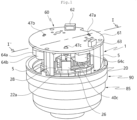
- the fan motor may be configured to have a housing frame 1 and a housing cover 10 according to this embodiment.
- the housing frame 1 and the housing cover 10 may be assembled to each other to create a predetermined space therebetween, and a motor unit C, which will be described below, may be embedded in the space.
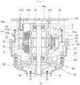
- the housing frame 1 and the housing cover 10 may support both ends of a rotor assembly 50 constituting the motor unit C. More specifically, the housing frame 1 and the housing cover 10 support a first bearing 53 and a second bearing 54 of the rotor assembly 50, respectively. To this end, the housing frame 1 and the housing cover 10 may be assembled with each other in the longitudinal direction of the rotor assembly 50.
- a first bearing receiving portion 3 may be located at the center of the housing frame 1, and a plurality of support legs 4 and 5 are radially provided around the first bearing receiving portion 3.
- the first bearing receiving portion 3 has a substantially circular structure and has an empty space in the center so that the first bearing 53 of the rotor assembly 50 is inserted therein.
- the first bearing 53 and the second bearing 54 of the rotor assembly 50 are arbitrarily set in order, and the order thereof may be reversed.
- the support legs 4 and 5 may extend from the outer circumferential surface of the first bearing receiving portion 3. More specifically, the support legs 4 and 5 is configured to include a connection bridge 4 extending in a direction orthogonal to the coupling direction of the housing frame 1 and the housing cover 10 and a leg body 5 extending in the coupling direction of the housing frame 1 and the housing cover 10 at the end of the connection bridge 4. According to the embodiment, a total of three support legs 4 and 5 are configured, and two or four or more support legs 4 and 5 may be configured.
- the housing cover 10 and an inverter unit 60 may be coupled to both ends of the leg body 5 of the support legs 4 and 5, respectively, the inverter unit 60 being to be described below.
- the inverter unit 60 may be coupled to the upper end of the leg body 5, and the housing cover 10 is assembled at the lower end of the leg body 5. Therefore, the inverter unit 60 may be spaced apart from the housing cover 10 by the height of the leg body 5, so that the insulation distance may be secured between parts of the inverter unit 60 and parts of the motor unit C.
- a reference numeral 8 denotes a fastening groove used for coupling with the housing cover 10.
- An empty space may be formed between the support legs 4 and 5, so that air may flow into the empty space.
- the impeller 70 which is to be described below, discharges air in the direction of the inverter while rotating. Herein, the air may be discharged into the empty space between the support legs 4 and 5, and thus not be disturbed by the housing frame 1.
- the empty space between the support legs 4 and 5 may refer to a kind of installation space, in which heat generating elements 64a to 64c of the inverter unit 60, and a neutral point terminal 30 and power terminals 40a, 40b, and 40c, etc., which are to be described below, are disposed. Since the installation space is partitioned into multiple spaces by the support legs 4 and 5, the parts may be also partitioned from each other to be installed in different installation spaces, and an insulation distance between the parts may be sufficiently secured. According to this embodiment, three installation spaces are provided.
- the housing cover 10 may form at least a part of the outer periphery of the fan motor according to the embodiment, and has a ring-shaped structure.
- the housing cover 10 may have a cover body 11 forming the outer periphery, and a second bearing receiving portion 12 provided at the center of the cover body 11, thereby supporting the second bearing 54 of the rotor assembly 50.
- Both the cover body 11 and the second bearing receiving portion 12 have a ring shape, and a plurality of connection arms 13 may be connected between the cover body 11 and the second bearing receiving portion 12.
- a first assembly groove 14 may be provided to correspond to the fastening groove 8 of the housing frame 1, at the outside of the connection arm 13, that is, at one end connected to the cover body 11.
- a second assembly groove 15 may be provided inside the connection arm 13 connected to the second bearing receiving portion 12. The second assembly groove 15 may be used for assembling between the diffuser 80 and the connection arm 13, which are to be described below.
- a first fastener B1 may be fastened into the first assembly groove 14 and the fastening groove 8.
- the motor unit C may be installed between the housing frame 1 and the housing cover 10.
- the motor unit C includes a stator assembly 20 and a rotor assembly 50, in order to implement the rotational operation of the fan motor.
- the stator assembly 20 is wound with a plurality of coil turns to generate electromagnetic induction, and the rotor assembly 50 is installed inside the stator assembly 20 and a part that actually rotates.
- the stator assembly 20 includes a stator core 21 in which a plurality of thin metal plates are stacked and insulators 22a and 22b coupled to the stator core 21 to insulate between the stator core 21 and the coil.
- the stator assembly 20 may be fixed between the housing frame 1 and the housing cover 10 to surround the rotor assembly 50, so that the rotor assembly 50 may be rotated in the center of the stator assembly 20.
- the insulator 22a and 22b may be assembled in the core of the stator assembly 20.
- the insulator 22a and 22b may be composed of a first insulator 22a and a second insulator 22b.
- the first insulator 22a and the second insulator 22b are assembled with each other.
- the first insulator 22a may be located at the top close to the inverter unit 60, and the second insulator 22b may be located at the bottom close to the housing cover 10.
- the order of the first insulator 22a and the second insulator 22b is arbitrarily determined and the order may be reversed.
- the first insulator 22a and the second insulator 22b may be integrally formed.
- a plurality of tooth portions 23 is provided inside the insulator 22a and 22b, and a slot 23' around which the coil is wound may be formed between the tooth portions 23. That is, the number of slots 23' may be provided as many as the number of tooth portions 23, and according to this embodiment, there are a total of three tooth portions 23, and the coil may be wound around three slots 23' to form three phases. As described below, in the stator assembly 20 according to this embodiment, the coil is wound in a Y-connection method to form three phases.
- the coil may be wound on the tooth portions 23 in a Y connection method, and at least three coils may be separately wound on the tooth portions 23. Accordingly, at least three coils implement U phase, V phase, and W phase.
- a U phase coil is wound on a first tooth portion 23a
- a V phase coil is wound on a second tooth portion 23b
- a W-phase coil is wound on a third tooth portion 23c.
- the insulators 22a and 22b are provided with a neutral point terminal 30 and power terminals 40a, 40b, and 40c, which are to be described below.
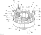
- the insulators 22a and 22b are provided in such a manner that a first storage unit 25 and a second storage portion 26 protrude toward the inverter unit 60.
- the neutral point terminal 30 is installed in the first storage unit 25, and the power terminals 40a, 40b, and 40c are installed in the second storage portion 26.
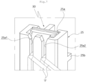
- a first storage space 25a may be opened upward in the first storage unit 25 to accommodate the neutral point terminal 30, and two first coil insertion grooves 25a1 and 25a2 are opened in a front-rear direction, that is, in a direction orthogonal to the direction in which the first storage space 25a is opened.
- the two first coil insertion grooves 25a1 and 25a2 may extend in a direction parallel to each other, and a coil may be inserted into the first coil insertion grooves 25a1 and 25a2 from above.
- the coil When the neutral point terminal 30 is inserted into the first storage unit 25 in a state that the coil is inserted into the first coil insertion grooves 25a1 and 25a2, the coil may be inserted into the neutral point receiving groove 35 of the neutral point terminal 30 and thus be electrically connected to the neutral point terminal 30.
- a first engaging end 25b may protrude from the surface of the first receiving part 25 to allow the coil to be engaged in the first engaging end 25b. That is, the coil partially inserted into the first coil insertion grooves 25a1 and 25a2 of the first receiving part 25 may be engaged by the first engaging end 25b to extend to the adjacent tooth portion 23.
- a second storage space 26a may be opened upward in the second storage portion 26 to accommodate the power terminals 40a, 40b, and 40c, and the second coil insertion groove 26a1 may be opened in a front-rear direction, that is, in a direction orthogonal to the direction in which the second storage space 26a is opened.
- the second coil insertion groove 26a1 may extend in the same direction as the second storage space 26a to allow the coil to be inserted from above.
- the coil When the power terminals 40a, 40b, and 40c are inserted into the second storage portion 26 in a state where the coil is inserted into the second coil insertion groove 26a1, the coil may be inserted into a power receiving grooves of each of the power terminals 40a, 40b, and 40c to be electrically connected to the power terminals 40a, 40b, and 40c.
- a second engaging end 26b may protrude from the surface of the second storage portion 26 to allow the coil to be engaged in the second engaging end 26b. That is, the coil partially inserted into the second coil insertion groove 26a1 of the second storage portion 26 may be engaged by the second engaging end 26b to extend to the adjacent tooth portion 23.
- three second storage portions 26 are provided at positions on one side of the coil constituting a U-phase, V-phase, and W-phase, respectively.
- the first storage portion 25 is provided on the opposite side of the coil constituting the U-phase.
- references U, V, and W denote coils constituting a U phase, V phase, and W phase, respectively.
- the insulator 22a and 22b may have a leg coupling portion 28.
- the leg coupling portion 28 may surround the leg body 5 of the support legs 4 and 5 of the housing frame 1, and protrude from the insulator 22a and 22b toward the inverter unit 60.
- the leg coupling portion 28 may surround a part of the surface of the leg body 5 to increase the coupling area between the insulator 22a and 22b and the housing frame 1, thereby increasing the coupling force.
- the leg coupling portion 28 has a substantially U-shaped cross section.
- the insulator 22a and 22b may have a hook 29.
- the hook 29 may protrude from the insulator 22a and 22b and serve to hang the coil. That is, the hook 29 accurately guides the moving direction of the coil by hanging a part of the coil, like the first engaging end 25b of the first storage portion 25 and the second engaging end 26b of the second storage portion 26 described above.
- the hook 29 may have an approximately inverted-L-shaped shape, and a plurality of hooks may be disposed around the edges of the insulators 22a and 22b.
- the terminal is composed of a neutral point terminal 30 and power terminals 40a, 40b, and 40c.
- the neutral point terminal 30 is composed of a terminal constituting a neutral point
- the power terminals 40a, 40b, and 40c are composed of terminals capable of supplying power.
- the power terminals 40a, 40b, and 40c may be classified into a first power terminal 40a, a second power terminal 40b, and a third power terminal 40c.
- the neutral point terminal 30 may be composed of a first plate 31a and a second plate 31b bent from the first plate 31a to extend to face the first plate 31a.
- the first plate 31a and the second plate 31b may constitute a neutral point terminal body 31, and a locking protrusion 33 may protrude from a side surface of the neutral point terminal body 31.
- the locking projection 33 may be a portion that allows the neutral point terminal 30 to be locked into the first storage portion 25, and is provided on both sides.
- a reference numeral 34 denotes a locking groove which is relatively recessed adjacent to the locking protrusion 33, and a locking protrusion (not shown) provided inside the first storage space 25a may be locked in the locking groove 34.
- connection rib 36 may be provided at the upper end of the first plate 31a, and the connecting rib 36 may protrude from the upper end of the first plate 31a toward the second plate 31b.
- the connection rib 36 may fill the gap between the first plate 31a and the second plate 31b. It may be appreciated that the connection rib 36 takes a role in maintaining the three-dimensional shape of the neutral point terminal 30. Of course, the connection rib 36 may protrude from the second plate 31b toward the first plate 31a.
- a neutral point receiving groove 35 into which the coil of the stator assembly 20 is inserted is formed in the first plate 31a and the second plate 31b.
- the coil is inserted into the neutral point receiving groove 35, and the neutral point receiving groove 35 may extend in a direction in which the neutral point terminal 30 is accommodated in the first storage portion 25.
- the neutral point receiving groove 35 is opened downward, so that the coil may be inserted through the opened portion.
- the coil is fitted into the neutral point receiving groove 35 while coupling the neutral point terminal 30 to the first storage portion 25, in a state that the coil is first inserted into the first coil insertion grooves 25a1 and 25a2 of the first storage portion 25.
- the neutral point receiving groove 35 is provided in a pair. A plurality of coils is inserted in such a manner as to be stacked in the pair of neutral point receiving grooves 35, and according to this embodiment, each coil constituting three phases, which is provided in the stator assembly 20, is inserted into the neutral point receiving grooves 35.
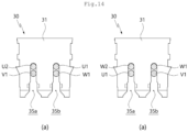
- the first groove portion 35a and the second groove portion 35b constituting the neutral point receiving groove 35 may form a kind of fork shape, and a state in which the coil is inserted into the first and second groove portions 35a and 35b is shown in FIGS. 14A and 14B.
- the neutral point terminal 30 constitutes the neutral point of a three-phase coil.
- the start end U1 refers to a part where the winding of the coil starts
- the termination end W1 refers to a part where the winding of the coil is completed.
- the two via ends U2 and V1 refer to parts that pass through the neutral point receiving groove 35 of the neutral point terminal 30, in the process where the coil is primarily wound and secondarily wound on any one of the tooth portions 23a to 23c and then is moved to another of the tooth portions 23a to 23c.
- the neutral point terminal 30 may be provided with the first plate 31a and the second plate 31b facing each other, so that the neutral point receiving groove 35 is also formed on each of the first plate 31a and the second plate 31b. That is, a pair of neutral point receiving grooves 35 is provided to be spaced apart from each other in the front-rear direction. Therefore, since a portion where the coil is fitted into the neutral point terminal 30 becomes two points, electrical connection between the coil and the neutral point terminal 30 may be made more stably.
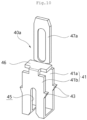
- FIG. 13 shows the power terminals 40a, 40b, and 40c.
- the power terminals 40a, 40b, and 40c are connected to the coils of the respective phase and serve to supply power to the coils constituting the respective phases.
- Each of the power terminals 40a, 40b, and 40c may be composed of a first connecting body 41a and a second connection body 41b that is bent from the first connection body 41a and extends to face the first connection body 41a.
- the first connection body 41a and the second connection body 41b constitute a power terminal body 41, and an engaging projection 43 protrudes from the side of the power terminal body 41.
- the engaging projection 43 may be a portion that allows the power terminals 40a, 40b, and 40c to be engaged in the second storage portion 26, and a pair of engaging projections 43 is provided on both of the first connection body 41a and the second connection body 41b.
- connection rib 46 may be provided at an upper end of the second connection body 41b.
- the connection rib 46 may protrude from the upper end of the second connection body 41b toward the first connection body 41a.
- the connection rib 46 may fill the gap between the first connection body 41a and the second connection body 41b. It may be appreciated that the connection rib 46 takes a role of maintaining the three-dimensional shape of the power terminals 40a, 40b, and 40c. Of course, the connection rib 46 may protrude from the first connection body 41a toward the second connection body 41b.
- Tab portions 47a, 47b, and 47c may protrude from the top of the first connection body 41a. That is, the tab portions 47a, 47b, and 47c may protrude upward, that is, toward the inverter unit 60 from the first connection body 41a, and thus be partially inserted into the inverter unit 60 to be electrically connected.
- the power receiving groove 45 into which the coil of the stator assembly 20 is inserted, may be formed in the first connection body 41a and the second connection body 41b.
- the coil is inserted into the power receiving groove 45, and the power receiving groove 45 extends in a direction in which the power terminals 40a, 40b, and 40c are accommodated in the second storage portion 26.
- the power receiving groove 45 is opened downward, so that the coil may be inserted through the opened portion.
- the coil may be inserted into the power receiving groove 45 while coupling the power terminals 40a, 40b, and 40c to the second storage portion 26, in the state that the coil is first inserted into the second coil insertion groove 26a1 of the second storage portion 26.
- the power terminals 40a, 40b, and 40c may be provided with the first connection body 41a and the second connection body 41b facing each other, so that the power receiving groove 45 is also formed in each of the first connection body 41a and the second connection body 41b. That is, a pair of power receiving grooves 45 is provided to be spaced apart from each other in the front-rear direction. Therefore, since the coil is inserted into the power terminals 40a, 40b, and 40c at two points, the electrical connection between the coil and the power terminals 40a, 40b, and 40c may be made more stably.
- the rotor assembly 50 located inside the stator assembly 20 may be configured to surround the rotation shaft 52 located at the center thereof.
- the rotor assembly 50 is rotationally disposed in the stator assembly 20.
- the rotor assembly 50 may be configured so that a disk-shaped core plate 51 is stacked and a magnet is disposed on an outer circumferential surface thereof.
- the rotor assembly 50 is rotated by electromagnetic induction generated between the magnet and the stator assembly 20, and the rotation shaft 52 rotates integrally with the rotor assembly 50.
- the rotor assembly 50 may include a first bearing 53 and a second bearing 54.
- the first bearing 53 and the second bearing 54 are spaced apart from each other. More precisely, the first bearing 53 may be provided relatively closer to the inverter unit 60, and the second bearing 54 is provided closer to the housing cover 10.
- the first bearing 53 may be fitted into the first bearing receiving portion 3 of the housing frame 1, and the second bearing 54 is fitted into the second bearing storage portion 12 of the housing cover 10.
- the inverter unit 60 may be coupled to the housing frame 1.
- the inverter unit 60 is a power supply device configured to be capable of varying a frequency to operate a fan motor at an arbitrary speed. That is, the inverter unit 60 may perform an operation of arbitrarily changing the frequency by varying the switching interval.
- the inverter unit 60 may be provided integrally with the fan motor and serves to supply power to the coil of the stator assembly 20.
- the inverter unit 60 may serve to apply three-phase power to the U, V, and W phases realized by the coil. To this end, the inverter unit 60 converts a rectified DC voltage into a predetermined AC voltage according to each phase and outputs the same. In addition, the fan motor may be driven according to the voltage input through the inverter unit 60. That is, current flows through the wound coil on each phase U, V, and W of the stator assembly 20 by the predetermined AC voltage converted by the inverter unit 60, so that a rotating magnetic field may be generated by the interaction of the magnetic field formed by the current and the magnet of the rotor assembly 50 to rotate the rotor assembly 50.
- the inverter unit 60 may include a circuit board 61 and a plurality of heat generating elements 64a to 64c mounted on the circuit board 61.
- the heat generating elements 64a to 64c may include MOSFETs or capacitors 64a to 64c for switching, but are not limited thereto. Since a lot of heat is generated from the heat generating elements 64a to 64c, it is necessary to effectively remove the heat of the heat generating elements 64a to 64c. Such a cooling structure will be described below.
- the circuit board 61 may be provided with a connector part 62 for receiving power from the outside, a sensing part 63 for sensing, and the like.
- the circuit board 61 may have a substantially disk shape. According to the embodiment, the circuit board 61 is concentric with the housing cover 10, and a diameter of the circuit board 61 is smaller than or equal to that of the housing cover 10.
- the heat generating elements 64a to 64c may be mounted on the bottom surface of the circuit board 61, that is, the surface facing the housing cover 10 and the impeller 70.
- the heat generating elements 64a to 64c include MOSFETs or capacitors 64a to 64c for switching.
- the capacitors 64a to 64c are cylindrical capacitors 64a to 64c. According to the embodiment, a total of three capacitors 64a to 64c may be provided. Alternatively, two or less or four or more capacitors may be mounted on the circuit board 61.
- the heat generating elements 64a to 64c may be provided to protrude from the bottom of the circuit board 61 toward the impeller 70, so that air discharged from the impeller 70 may be discharged to the outside through the heat generating elements 64a to 64c.
- the overall height of the fan motor may be lowered by at least the height of the heat generating elements 64a to 64c, compared to when the heat generating elements 64a to 64c may be provided upward (upward in FIG. 1 ) from the top of the circuit board 61.
- the capacitors 64a to 64c may be installed closer to the outer edge than the center of the circuit board 61. Accordingly, the capacitors 64a to 64c are clearly revealed between the support legs 4 and 5 of the housing frame 1 as shown in FIG. 1 .
- the heat generating elements 64a to 64c may be positioned on the discharge path in which the air is discharged to the outside of the fan motor through the impeller 70 and the diffuser 80. Accordingly, the heat generating elements 64a to 64c are cooled by the impeller 70 and the diffuser 80, thereby preventing deterioration of the fan motor due to heat generation. That is, since the air discharged by the impeller 70 is directly transmitted to the heat generating elements 64a to 64c, the heat generating elements 64a to 64c may be cooled without a separate cooling device.
- a plurality of coupling holes 67 may be provided in the circuit board 61, and a part of the support legs 4 and 5 of the housing frame 1 may be fitted into the coupling holes 67. That is, when a portion protruding from the support legs 4 and 5 is inserted into the coupling hole 67, the circuit board 61 may be fixed to the housing frame 1.
- the circuit board 61 may be fixed to the housing frame 1 more firmly via a method such as soldering.
- the circuit board 61 may be provided with tap holes 66a to 66c.
- the tap holes 66a to 66c are made through the circuit board 61, and the ends of the respective tap portions 47a to 47c of the respective power terminals 40a to 40c described above may pass through the respective tap holes 66a to 66c.
- the tab portions 47a, 47b, and 47c may be fixed to the circuit board while being electrically connected to the circuit board 61.
- the tap holes 66a to 66c are formed in the circuit board 61 according to the number and position of the three power terminals 40a, 40b, and 40c.
- An impeller 70 may be assembled in the rotor assembly 50.
- the impeller 70 has a shaft coupling hole 73, into which the rotation shaft 52 is vertically inserted, at the center thereof.
- the shaft coupling hole 73 may be formed in the hub 71 supporting the overall rigidity of the impeller 70, so that the rotational force of the rotation shaft 52 may be well transmitted to the impeller 70.
- the hub 71 may have a flat plate structure, or may have an inclination surface that is inclined downward in the radial direction from the center of rotation.
- a plurality of blades 72 may be radially provided on the bottom of the hub 71 to pressurize air.
- the upper end of the blade 72 is in close contact with the inner surface of a fan cover 85.
- a diffuser 80 may be stacked on the impeller 70.
- the diffuser 80 serves to guide the air sucked through an air inlet 87 of the fan cover 85 toward the inverter unit 60.
- the diffuser 80 may include a guide body 81 having the form of a disk, and a plurality of guide vanes 82 formed on the outer circumferential surface of the guide body 81.
- a shaft through hole 83 may be formed in the center of the guide body 81, and at least a part of the second bearing 54 of the rotor assembly 50 may be accommodated in the shaft through hole 83.
- a plurality of guide holes 84 may be formed around the shaft through hole 83.
- the guide hole 85 may correspond to the second assembly groove 15, and the guide hole 85 may be fastened to the second assembly groove 15 through a second faster B2.
- the fan cover 85 may be coupled to the opposite side of the diffuser 80 on the basis of the impeller 70.
- the fan cover 85 covers at least a part of the housing cover 10, and according to the embodiment, the housing cover 10 and the fan cover 85 may be coupled to each other using the bracket 90.
- the body 91 of the bracket 90 may be ring-shaped with a central portion 92 being empty to surround the housing cover 10.
- the fan cover 85 may be directly connected to the housing cover 10.
- An air intake port 87 through which air is sucked into the fan motor, may be provided in the upper central portion of the fan cover 85.
- the fan cover body 86 of the fan cover 85 has a shape inclined downward from the air inlet 87 as it moves away from the central axis of the fan motor, and the lower end of the fan cover 85 covers the housing cover 10. Since the fan cover 85 does not directly support the motor unit C, among parts of the fan motor, the fan cover 85 may be made of a lightweight synthetic resin material.
- the air (arrow 1) introduced into the air inlet 87 of the fan cover 85 is pressurized and discharged by the impeller 70, moves along the vanes 82 of the diffuser 80 (arrow 2), and finally is discharged from the fan cover 85 toward the inverter unit 60 (arrow (3)) . Therefore, the air discharged by the impeller 70 may result in cooling the heat generating elements 64a to 64c of the inverter unit 60.
- the heat generating elements 64a to 64c are located on a path through which air is discharged, such cooling may be performed more effectively.
- the plurality of heat generating elements 64a to 64c may be installed on the circuit board 61 constituting the inverter unit 60, and terminals coupled to the stator assembly 20 may be disposed between the heat generating elements 64a to 64c.
- virtual extension lines A1, A2, and A3 may be located along the direction in which the support legs 4 and 5 of the housing frame 1 extend on the basis of the center of the circuit board 61, and it may be appreciated that the installation space is compartmented into multiple installation spaces between the extension lines.
- both the heat generating elements 64a to 64c and the third power terminal 40c may be disposed in a first installation space from the line A1 to the line A2, and only the neutral point terminal 30 and the first power terminal 40a may be arranged in a third installation space from the line A3 to the line A1 marked with a reference symbol K.
- the neutral point receiving groove 35 includes a first groove portion 35a and a second groove portion 35b.
- the neutral point terminal may interfere with other components (heat generating elements 64a to 64c).
- the heat generating elements 64a to 64c may be excluded in the installation space from the line A3 to the line A1 where the neutral point terminal 30 is disposed, thereby preventing such interference.
- this makes it possible to secure enough insulation distance between the components.
- two heat generating elements 64a to 64c and one second power terminal 40b may be disposed in a second installation space from the line A2 to the line A3.
- FIG. 11 shows a plan view of the stator assembly 20 constituting the motor.
- a total of three coils are wound in the stator assembly 20 in a separate manner, each constituting three phases (U phase, V phase, and W phase).
- the coils constituting these three phases are not disconnected from each other, but are wound in a continuous manner. Accordingly, the coils may be separately wound around different tooth portions 23a to 23c and connected to different power terminals 40a, 40b, and 40c.
- a start end of the coil constituting the U-phase of the three phases is first inserted into the first groove portion 35a or the second groove portion 35b of the neutral point terminal 30 (arrow (1)) .
- the coil is wound around the first tooth portion 23a, which is one of the tooth portion 23, a plurality of times, passes by the first power terminal 40a, and then is wound around the first tooth portion 23a in an overlapping manner (arrow 2). Therefore, the U phase has a parallel configuration as shown in FIG. 13 .
- the coil moves while surrounding the surface of the first insulator 22a in a counterclockwise direction.
- the coil passes by the surface of the second storage portion 26 in which the second power terminal 40b adjacent to the second tooth portion 23b constituting the V phase is accommodated (arrow 4).
- the coil is hooked on the hook 29, the coil is wound around the second tooth portion 23b, which is another of the tooth portion 23, a plurality of times, then inserted into the second power terminal 40b, and then wound around the second tooth portion 23b in an overlapping manner (arrow (5)) . Therefore, the V phase has a parallel configuration as shown in FIG. 13 .
- the coil may move while surrounding the surface of the first insulator 22a in a clockwise direction (arrow 6), and may be inserted into the first groove portion 35a or the second groove portion 35b of the neutral point terminal 30 (arrow 6').
- the coil moves while surrounding the surface of the first insulator 22a in a clockwise direction, and is wound around the third tooth portion 23c, which is the remaining the tooth portions 23 constituting the W phase (arrow 7).
- the coil wound around the third tooth portion 23c a plurality of times is fitted into the third power terminal 40c, and is wound around the third tooth portion 23c in an overlapping manner (arrow 8). Therefore, the W phase has a parallel configuration as shown in FIG. 13 .
- the coil moves while surrounding the surface of the first insulator 22a in a counterclockwise direction (arrow 9), and finally, the coil is fitted into the first groove portion 35a or the second groove portion 35b of the neutral point terminal 30 (arrow 10).
- the starting end U1 constituting the U phase and the terminating end W2 of the coil at which the winding of the coil constituting the W phase is terminated may be fitted into the second groove portion 35b of the neutral point terminal 30 at different heights from each other.
- the via end U2 of the coil moving to wind the V phase after winding the U phase and the via end V1 of the coil moving to wind the W phase after winding the V phase may be fitted into the first groove portion 35a at different heights from each other.
- the order in which the coils are fitted into the neutral point terminal 30 is not limited thereto, and may be changed as shown in FIG. 14B, which is then to be seen outside the scope of the invention.
- the neutral point terminal 30 since the neutral point terminal 30 only has to configure a neutral point, the order and position in which the coils are inserted may be variously modified. In addition, the order in which the coils are wound may be started from W phase instead of U phase.
- the stator core 21 of the stator assembly 20 may be provided with three slots 23', so that the coil is composed of three phases of U, V, and W.
- the coil is wound in the slot 23', passes by the power terminals 40a, 40b, and 40c, and then is wound in an overlapping manner, so that the coil is disposed in parallel between the neutral point terminal 30 and the power terminals 40a, 40b, and 40c.
- two strands of coil are not wound at the same time, but are wound on each slot 23' in such a manner that the coil is primarily wound, passes by the power terminal 40a, 40b, and 40c, and then secondarily wound, so that each phase is connected in parallel.
- FIG. 13 Such a configuration is shown in FIG. 13 .
- the coil started from the neutral point terminal 30 constituting the neutral point is wound around the first tooth portion 23a constituting the U phase (arrow 1), passes by the first power terminal 40a, and then wound around the same first tooth portion 23a again (arrow 2), whereby the U-phase is connected in parallel.
- the coil passes by the neutral point terminal 30, which is a neutral point, is wound around the second tooth portion 23b constituting the V phase (arrow 3), passes by the second power terminal 40b, and then is wound around the same second tooth portion 23b again (arrow (4)), whereby the V phase is connected in parallel.
- the coil passes by the neutral point terminal 30, which is a neutral point, is wound around the third tooth portion 23c constituting the W phase (arrow 5), passes by the third power terminal 40c, and then is wound around the same third tooth portion 23c again (arrow (6)), whereby the W phase is also connected in parallel.
- each phase since each phase is connected in parallel and the number of tooth portions 23 is the same as the number of phases, the structure may be simple, and winding may be easily made without a need to wind two coils at the same time.
- each phase since each phase is configured in parallel, it is possible to achieve high performance without increasing the diameter of the coil.
- the coil constituting each phase may be inserted into the neutral point terminal 30 on a per-strand basis, according to the method as described above.
- the neutral point receiving groove 35 required for the neutral point terminal 30 is composed of only two grooves (a first groove portion 35a and a second groove portion 35b).
- the coil may be primarily wound around each of the tooth portions 23a to 23c, secondarily wound around the first tooth portion 23a in an overlapping manner via the first power terminal 40a, passes by the neutral point terminal 30, secondarily wound around the second tooth portion 23b in an overlapping manner via the second power terminal 40b, passes by the neutral point terminal 30 again, and then is secondarily wound around the third tooth portion 23c in an overlapping manner via the third power terminal 40c.
- the present disclosure is not limited thereto.
- the inverter unit 60 may be configured separately, or may also be applied to a motor that perform various functions, in addition to the fan motor.
Landscapes
- Engineering & Computer Science (AREA)
- Power Engineering (AREA)
- Microelectronics & Electronic Packaging (AREA)
- Manufacturing & Machinery (AREA)
- Physics & Mathematics (AREA)
- Thermal Sciences (AREA)
- Insulation, Fastening Of Motor, Generator Windings (AREA)
Description
- The present disclosure relates to a motor and a home appliance and, more specifically, to a brushless motor in which an inverter is integrally provided and a home appliance including the same.
- Motors are used for various purposes, and among them, a fan motor is a product in which a motor that provides rotational force and a fan rotated by the motor to generate airflow are integrally configured. The fan motor is widely used in home appliances that require airflow. For example, the fan motor may be used for a vacuum cleaner, an outdoor unit of an air conditioner, or an air purifier.
- Recently, a brushless direct current (BLDC) motor is widely used as a motor of the fan motor. There are advantages that the BLDC motor is capable of preventing friction and abrasion which is a disadvantage of a DC motor in the related art, and has a relatively high efficiency. The BLDC motor is a motor in which brushes and commutators are eliminated from DC motors and electronic commutation mechanisms are provided.
- In particular, among BLDC motors, there is a motor in which an inverter unit is integrally embedded. When the inverter unit is integrally provided in the motor, the structure can be simplified, but there is a problem in that the overall size of the motor increases. In particular, electronic components such as a cylindrical capacitor provided in the inverter unit increase the overall height of the motor, thereby making it difficult to downsize the motor.
- To increase the performance of the motor without increasing the size of the motor, the current capacity must be increased. To this end, the diameter of the coil wound around the stator may be made thicker. However, when the coil is thicker, there are problems that winding becomes difficult, and the connector or harness should be enlarged according to the coil.
- To solve such problems, the number of slots around which the coils are wound should be increased. As the number of slots is increased, the size of the stator increases and the structure thereof becomes complicated. Alternatively, coils of each phase may be connected in parallel by double-winding the coil. However, it is necessary to accurately connect two lead wires (coils) on each phase of the power supply unit in order to double-wind the coil, whereby the winding operation is difficult.
- In addition, in the case of a three-phase multi-pole motor, a total of six coils are connected at the neutral point. In the case of such a parallel connection, since there are relatively many parts to be connected, the probability of incorrect connection is high and thus product reliability is degraded.
- In addition, since at least six coils must be connected at the neutral point, the size of the neutral point terminal increases. Accordingly, there is a problem in that it is difficult to design the neutral terminal and other components, for example, components of an inverter so as not to interfere with each other. In
Korean Patent Application Publication No. 10-2019-0007907 Korean Patent No. 10-0845867 - Meanwhile, a plurality of components is provided in the inverter unit integrally provided in the motor. Herein, since high heat is generated from the electronic components provided in the inverter unit, the heat must be effectively removed. For example, a heat dissipation structure capable of removing the heat generated from a MOSFET device or a capacitor provided in the PCB of the inverter unit is required.
- As in
Korean Patent No. 10-0253231 Korean Patent Application Publication No. 10-2019-0008609 -
- [Document 1]
Korean Patent Application Publication No. 10-2019-0007907 - [Document 2]
Korean Patent No. 10-0845867 - [Document 3]
Korean Patent No. 10-0253231 - [Document 4]
Korean Patent Application Publication No. 10-2019-0008609 -
JP 2002 199636 A - Accordingly, the present disclosure has been made keeping in mind the above problems occurring in the related art, and an objective of the present disclosure is to reduce the size of the neutral point terminal forming the neutral point when the coil is wound in double in a three-phase Y connection method.
- Another objective of the present disclosure is to reduce the size of the neutral point terminal so that the heat generating element of the motor inverter unit and the neutral point terminal do not interfere with each other.
- Another objective of the present disclosure is to cause a heat generating element (MOSFET element, capacitor, etc.) provided in the inverter unit of the motor to be cooled by the impeller of the motor.
- In order to achieve the above objectives, a motor according to
claim 1 is provided. - Therefore, although each coil constituting three phases of U, V, and W is wound in double, the coil is wound on a per-strand basis, whereby each phase is connected in parallel. Accordingly, it is possible to easily perform the winding process while improving the performance of the motor. In addition, the neutral point terminal can be miniaturized.
- In addition, the coil may be primarily wound and secondarily wound around one tooth portion of the plurality of tooth portions, pass by the neutral point terminal, and then be primarily wound and secondarily wound around another tooth portion. As described above, according to the present disclosure, since the coils are wound on a per-strand basis in order and then pass by the neutral point terminal, the start end, the terminating end, and the via end of the coil which passes by the neutral point terminal may be configured with one strand.
- In addition, the stator assembly may further include an insulator coupled to a top of the stator, and the insulator may include a storage portion for accommodating the plurality of power terminals and the neutral point terminal. The storage portion may include a first storage portion and a second storage portion. Herein, at least a part of the neutral point terminal may be accommodated in the first storage portion, and at least a part of the power terminal is accommodated in the second storage portion.
- In addition, the stator core of the stator assembly may be provided with three tooth portions, and the coil may be wound around each of the three tooth portions to form three phases of U, V, and W. Herein, (i) U phase winding may be performed in such a manner that a start end of the coil passes by the neutral point receiving groove, is primarily wound around the first tooth portion, passes by the first power terminal, and then secondarily wound around the first tooth portion in an overlapping manner; (ii) V phase winding may be performed in such a manner that a via end of the coil, in which the U phase winding is completed, passes by the neutral point receiving groove, primarily wound around the second tooth portion, passes by the second power terminal, and then secondarily wound around the second tooth portion in an overlapping manner; (iii) W phase winding may be performed in such a manner that a via end of the coil, in which the V phase winding is completed, passes by the neutral point receiving groove, primarily wound around the third tooth portion, passes by the third power terminal, and then secondarily wound around the third tooth portion in an overlapping manner; and (iv) a terminating end of the coil, in which the W phase winding is completed, may pass through the neutral point receiving groove. Therefore, since the coil is wound on a per-strand basis, the winding process becomes easy while improving the performance of the motor.
- In addition, the neutral point terminal may include a first plate and a second plate bent from the first plate and extending to face the first plate, the first plate and the second plate being formed with a neutral point receiving groove into which the coil of the stator assembly is inserted. Therefore, the neutral point receiving groove can contact the coil at at least two points, thereby increasing the stability of the electrical connection.
- In addition, the motor may further include a housing frame having a first bearing receiving portion; and a housing cover connected to the housing frame and having a second bearing receiving portion, in which the rotor assembly and the stator are installed. An inverter unit may be provided in the housing frame corresponding to an opposite side of the impeller on the basis of the housing cover so that heat generating elements face the impeller. Herein, two neutral point receiving grooves are formed in which the coils constituting the three phases may be inserted in the neutral point terminal at different heights. Therefore, according to the present disclosure, since the heat generating elements (MOSFET elements or capacitors, etc.) in the inverter may be installed to face the impeller and be cooled by the impeller, and the size of the neutral point terminal can be reduced, interference between the heat generating element of the inverter unit and the neutral point terminal can be prevented.
- In addition, a plurality of the heat generating elements may be mounted on a circuit board constituting the inverter unit, and the stator assembly may be provided with a neutral point terminal connecting the neutral point of the three phase coil. The neutral point terminal may be provided to protrude toward the inverter from a position avoiding the heat generating elements. Therefore, even when the heat generating element is installed in the direction of the stator assembly, the heat generating element may not interfere with the neutral point terminal, and the overall height of the motor may be lowered.
- In addition, the housing frame may include a first bearing portion provided in a center thereof; a plurality of connection bridges extending radially from the first bearing receiving portion; and a leg body. The leg body may extend along a direction in which the housing frame and the housing cover are assembled at an end of the connection bridge, and the housing cover may be assembled at one end of the leg body, and the inverter unit may be assembled at the other end of the leg body. Therefore, the heat generating element protruding from the inverter unit toward the stator assembly may make it possible to secure a sufficient insulation distance from the coil of the stator assembly and to dissipate the heat by the spaced distance.
- In addition, the heat generating element may be provided at a position closer to an outer edge of the circuit board than a center of the circuit board constituting the inverter unit. Therefore, the heat generating elements may be disposed close to the outer edge of the inverter, particularly on the discharge path of the air discharged to the outside of the fan motor through the impeller and the diffuser. Therefore, the heat generating elements can be cooled by the impeller and the diffuser, and deterioration of the fan motor due to heat generation can be prevented.
- In addition, two neutral point receiving grooves may extend in a direction parallel to each other, and two coils may be inserted into the two neutral point receiving grooves at different heights to be electrically connected to the neutral point terminal. Accordingly, the neutral point terminal may form a neutral point.
- The stator core of the stator assembly may be provided with three slots, and the coil is composed of three phases of U, V, and W. The coil may be wound around the slot, passes by the power terminal, and then is wound in an overlapping manner, so that the coil may be disposed in parallel between the neutral point terminal and the power terminal. Accordingly, the size of the neutral point terminal connecting the coils in three phases can be reduced, and interference between the heat generating element of the inverter unit and the neutral terminal can be prevented, thereby increasing the design freedom of the fan motor.
- The motor and the home appliance having the same which are described above according to the present disclosure have the following effects.
- According to the present disclosure, each coil constituting three phases of U, V, and W may be wound in double (primary winding and secondary winding). Herein, two coils may be not wound at the same time, but wound in an overlapping manner so that the coil is primarily wound, passes by the power terminal, and then secondarily wound, whereby each phase may be connected in parallel. Therefore, since the coils are wound on a per-strand basis, there is an effect of facilitating the winding process while improving the performance of the motor.
- In addition, according to the present disclosure, when the coils of each phase are connected in parallel, the coils may be wound around each tooth portion on a per-strand basis, whereby the number of neutral point receiving grooves, by which the coil passes, in the neutral point terminal, can also be reduced. Therefore, the overall size of the neutral point terminal can be reduced, whereby the motor can be miniaturized, and interference with peripheral components such as the heat generating element of the inverter can be prevented more easily.
- In addition, according to the present disclosure, the neutral point terminal may be configured so that two plates (first plate and second plate) face each other, and each plate may be configured so that the neutral point receiving grooves are connected to each other. Therefore, when each coil passes by the neutral point terminal, the coil may be inserted into each neutral point receiving groove in the two plates. Therefore, the neutral point terminal and the coil can be electrically connected to each other at two points, thereby improving the operation reliability of the motor.
- In addition, according to the present disclosure, the inverter may be integrally coupled to the fan motor to simplify the overall structure of the motor system, and at the same time, the heat generating elements (such as MOSFET element or capacitor) in the inverter may be installed to face the impeller and thus cooled. That is, the heat generating elements can be cooled by the airflow generated by the impeller without a separate cooling device, whereby there is an effect of improving the performance and efficiency of the fan motor while miniaturizing the fan motor.
- In addition, according to the present disclosure, the coil may be wound in double in order to improve the performance of the motor. Herein, the coil is wound around the tooth portions on a per-strand basis in order to form each phase. Accordingly, the size of the neutral point terminal connecting the coil in three phases can be reduced, and interference between the heat generating element of the inverter and the neutral point terminal can be prevented, thereby increasing the design freedom of the fan motor.
- In addition, according to the present disclosure, terminals coupled to the stator assembly may be disposed between the heat generating elements of the inverter. Therefore, even when the heat generating elements and terminals are installed in the direction facing each other, interference between the heat generating elements and the terminals can be prevented, thereby effectively cooling the heat generating element.
- In addition, according to the present disclosure, the heat generating elements may be disposed close to the outer edge of the inverter, particularly on the discharge path of the air discharged to the outside of the fan motor through the impeller and the diffuser. Therefore, the heat generating elements can be cooled by the impeller and the diffuser, and deterioration of the fan motor due to heat generation can be prevented.
- In addition, according to the present disclosure, a plurality of support legs may be radially extended in the housing frame supporting the inverter, and an empty space may be located between the support legs. Herein, since the support leg can make it possible to secure the insulation distance by separating the inverter from the stator assembly, and air is discharged into the empty space between the support legs, the air can flow smoothly.
- In particular, since heat generating elements may be arranged in the installation space formed between the support legs, air discharged from the impeller can be discharged into the empty space between the support legs through the heat generating element. Therefore, the heat generating element can be cooled more effectively.
- In addition, the inverter unit may be spaced apart from the stator assembly by the height of the support leg of the housing frame. Therefore, the heat generating element protruding from the inverter unit toward the stator assembly can make it possible to secure the insulation distance sufficient from the coil of the stator assembly and radiate the heat as much as the spaced distance.
- In addition, only the terminal may be arranged, and alternatively the heat generating element may be arranged, in some installation spaces of a plurality of installation spaces formed between the support legs of the housing frame supporting the inverter. Therefore, interference between the terminal and the heat generating element can be more reliably prevented, and the insulation distance between each component can be sufficiently secured.
- The above and other objectives, features, and other advantages of the present disclosure will be more clearly understood from the following detailed description when taken in conjunction with the accompanying drawings, in which:
-
FIG. 1 is a perspective view showing the configuration of an embodiment of a fan motor according to the present disclosure; -
FIG. 2 is an exploded perspective view of components constituting the fan motor shown inFIG. 1 ; -
FIG. 3 is a cross-sectional view taken along a line I-I' ofFIG. 1 ; -
FIG. 4 is a perspective view showing the configuration of a stator assembly according to an embodiment of the present disclosure; -
FIG. 5 is a perspective view showing the configuration of an inverter according to an embodiment of the present disclosure; -
FIG. 6 is a plan view showing the configuration of an inverter according to an embodiment of the present disclosure; -
FIG. 7 is a perspective view showing a state in which a neutral point terminal is assembled to a stator assembly according to an embodiment of the present disclosure; -
FIG. 8 is a perspective view showing the configuration of a neutral point terminal according to an embodiment of the present disclosure; -
FIG. 9 is a perspective view showing a state in which a power terminal is assembled to a stator assembly according to an embodiment of the present disclosure; -
FIG. 10 is a perspective view showing the configuration of a power terminal according to an embodiment of the present disclosure; -
FIG. 11 is a plan view showing the configuration of a stator assembly according to an embodiment of the present disclosure; -
FIG. 12 is a conceptual diagram showing a sequence in which the coil is wound on a stator assembly according to an embodiment of the present disclosure; -
FIG. 13 is a circuit diagram showing a coil connection structure of a stator assembly according to an embodiment of the present disclosure; and -
FIGS. 14A and 14B are front views showing a state in which a coil is coupled to a neutral point terminal according to an embodiment of the present disclosure. - Hereinafter, an embodiment of the present disclosure will be described in detail with reference to the accompanying drawings. It should be noted that in adding reference numerals to the components of each drawing, the same components have the same reference numerals when possible, even if they are displayed on different drawings. In addition, in describing the embodiment of the present disclosure, when it is determined that a detailed description of a related known configuration or function interferes with the understanding of the present disclosure, the detailed description thereof is omitted.
- In addition, in describing a component of the embodiment of the present disclosure, terms such as first, second, A, B, (a), and (b) may be used. These terms are only for distinguishing the component from other components, and the nature or order of the components is not limited by the term. When a component is described as being "connected", "coupled", or "attached" to other component, the component can be directly connected or coupled to the other component. Herein, it will be understood that still other components may be "connected", "coupled", or "attached" between the components.
- The present disclosure relates to a motor and a home appliance having the same. Herein, the home appliance may include various electronic products, such as a vacuum cleaner, an air purifier, and a ventilator, requiring a motor. Further, the motor according to the present disclosure is a motor with an inverter installed, as a brushless direct current (BLDC) motor. Hereinafter, among motors, a fan motor will be described as an example, and the present disclosure will be described on the basis of the structure of the fan motor.
- Referring to
FIGS. 1 and2 , the fan motor may be configured to have ahousing frame 1 and ahousing cover 10 according to this embodiment. Thehousing frame 1 and thehousing cover 10 may be assembled to each other to create a predetermined space therebetween, and a motor unit C, which will be described below, may be embedded in the space. - The
housing frame 1 and thehousing cover 10 may support both ends of arotor assembly 50 constituting the motor unit C. More specifically, thehousing frame 1 and thehousing cover 10 support afirst bearing 53 and asecond bearing 54 of therotor assembly 50, respectively. To this end, thehousing frame 1 and thehousing cover 10 may be assembled with each other in the longitudinal direction of therotor assembly 50. - A first
bearing receiving portion 3 may be located at the center of thehousing frame 1, and a plurality ofsupport legs bearing receiving portion 3. The firstbearing receiving portion 3 has a substantially circular structure and has an empty space in the center so that thefirst bearing 53 of therotor assembly 50 is inserted therein. For reference, thefirst bearing 53 and thesecond bearing 54 of therotor assembly 50 are arbitrarily set in order, and the order thereof may be reversed. - The
support legs bearing receiving portion 3. More specifically, thesupport legs connection bridge 4 extending in a direction orthogonal to the coupling direction of thehousing frame 1 and thehousing cover 10 and aleg body 5 extending in the coupling direction of thehousing frame 1 and thehousing cover 10 at the end of theconnection bridge 4. According to the embodiment, a total of threesupport legs more support legs - The
housing cover 10 and aninverter unit 60 may be coupled to both ends of theleg body 5 of thesupport legs inverter unit 60 being to be described below. Referring toFIG. 2 , theinverter unit 60 may be coupled to the upper end of theleg body 5, and thehousing cover 10 is assembled at the lower end of theleg body 5. Therefore, theinverter unit 60 may be spaced apart from thehousing cover 10 by the height of theleg body 5, so that the insulation distance may be secured between parts of theinverter unit 60 and parts of the motor unit C.A reference numeral 8 denotes a fastening groove used for coupling with thehousing cover 10. - An empty space may be formed between the
support legs impeller 70, which is to be described below, discharges air in the direction of the inverter while rotating. Herein, the air may be discharged into the empty space between thesupport legs housing frame 1. - The empty space between the
support legs elements 64a to 64c of theinverter unit 60, and aneutral point terminal 30 andpower terminals support legs - The
housing cover 10 may form at least a part of the outer periphery of the fan motor according to the embodiment, and has a ring-shaped structure. Thehousing cover 10 may have acover body 11 forming the outer periphery, and a secondbearing receiving portion 12 provided at the center of thecover body 11, thereby supporting thesecond bearing 54 of therotor assembly 50. Both thecover body 11 and the secondbearing receiving portion 12 have a ring shape, and a plurality ofconnection arms 13 may be connected between thecover body 11 and the secondbearing receiving portion 12. - A
first assembly groove 14 may be provided to correspond to thefastening groove 8 of thehousing frame 1, at the outside of theconnection arm 13, that is, at one end connected to thecover body 11. In addition, asecond assembly groove 15 may be provided inside theconnection arm 13 connected to the secondbearing receiving portion 12. Thesecond assembly groove 15 may be used for assembling between thediffuser 80 and theconnection arm 13, which are to be described below. A first fastener B1 may be fastened into thefirst assembly groove 14 and thefastening groove 8. - The motor unit C may be installed between the
housing frame 1 and thehousing cover 10. The motor unit C includes astator assembly 20 and arotor assembly 50, in order to implement the rotational operation of the fan motor. Thestator assembly 20 is wound with a plurality of coil turns to generate electromagnetic induction, and therotor assembly 50 is installed inside thestator assembly 20 and a part that actually rotates. - The
stator assembly 20 includes astator core 21 in which a plurality of thin metal plates are stacked andinsulators stator core 21 to insulate between thestator core 21 and the coil. Thestator assembly 20 may be fixed between thehousing frame 1 and thehousing cover 10 to surround therotor assembly 50, so that therotor assembly 50 may be rotated in the center of thestator assembly 20. - Referring to
FIGS. 3 and4 , theinsulator stator assembly 20. According to this embodiment, theinsulator first insulator 22a and asecond insulator 22b. Thefirst insulator 22a and thesecond insulator 22b are assembled with each other. Thefirst insulator 22a may be located at the top close to theinverter unit 60, and thesecond insulator 22b may be located at the bottom close to thehousing cover 10. Of course, the order of thefirst insulator 22a and thesecond insulator 22b is arbitrarily determined and the order may be reversed. Alternatively, thefirst insulator 22a and thesecond insulator 22b may be integrally formed. - A plurality of
tooth portions 23 is provided inside theinsulator tooth portions 23. That is, the number of slots 23' may be provided as many as the number oftooth portions 23, and according to this embodiment, there are a total of threetooth portions 23, and the coil may be wound around three slots 23' to form three phases. As described below, in thestator assembly 20 according to this embodiment, the coil is wound in a Y-connection method to form three phases. - In this way, the coil may be wound on the
tooth portions 23 in a Y connection method, and at least three coils may be separately wound on thetooth portions 23. Accordingly, at least three coils implement U phase, V phase, and W phase. For example, a U phase coil is wound on afirst tooth portion 23a, a V phase coil is wound on asecond tooth portion 23b, and a W-phase coil is wound on athird tooth portion 23c. - The
insulators neutral point terminal 30 andpower terminals FIG. 4 , theinsulators first storage unit 25 and asecond storage portion 26 protrude toward theinverter unit 60. Theneutral point terminal 30 is installed in thefirst storage unit 25, and thepower terminals second storage portion 26. According to this embodiment, there are onefirst storage unit 25 and a total of threesecond storage portions 26. - Referring to
FIGS. 4 and7 , afirst storage space 25a may be opened upward in thefirst storage unit 25 to accommodate theneutral point terminal 30, and two first coil insertion grooves 25a1 and 25a2 are opened in a front-rear direction, that is, in a direction orthogonal to the direction in which thefirst storage space 25a is opened. The two first coil insertion grooves 25a1 and 25a2 may extend in a direction parallel to each other, and a coil may be inserted into the first coil insertion grooves 25a1 and 25a2 from above. When theneutral point terminal 30 is inserted into thefirst storage unit 25 in a state that the coil is inserted into the first coil insertion grooves 25a1 and 25a2, the coil may be inserted into the neutralpoint receiving groove 35 of theneutral point terminal 30 and thus be electrically connected to theneutral point terminal 30. - A first
engaging end 25b may protrude from the surface of the first receivingpart 25 to allow the coil to be engaged in the firstengaging end 25b. That is, the coil partially inserted into the first coil insertion grooves 25a1 and 25a2 of the first receivingpart 25 may be engaged by the firstengaging end 25b to extend to theadjacent tooth portion 23. - A
second storage space 26a may be opened upward in thesecond storage portion 26 to accommodate thepower terminals second storage space 26a is opened. The second coil insertion groove 26a1 may extend in the same direction as thesecond storage space 26a to allow the coil to be inserted from above. When thepower terminals second storage portion 26 in a state where the coil is inserted into the second coil insertion groove 26a1, the coil may be inserted into a power receiving grooves of each of thepower terminals power terminals - A second
engaging end 26b may protrude from the surface of thesecond storage portion 26 to allow the coil to be engaged in the secondengaging end 26b. That is, the coil partially inserted into the second coil insertion groove 26a1 of thesecond storage portion 26 may be engaged by the secondengaging end 26b to extend to theadjacent tooth portion 23. - Referring to
FIGS. 4 and11 , threesecond storage portions 26 are provided at positions on one side of the coil constituting a U-phase, V-phase, and W-phase, respectively. According to this embodiment, thefirst storage portion 25 is provided on the opposite side of the coil constituting the U-phase. For reference, references U, V, and W denote coils constituting a U phase, V phase, and W phase, respectively. - The
insulator leg coupling portion 28. Theleg coupling portion 28 may surround theleg body 5 of thesupport legs housing frame 1, and protrude from theinsulator inverter unit 60. Theleg coupling portion 28 may surround a part of the surface of theleg body 5 to increase the coupling area between theinsulator housing frame 1, thereby increasing the coupling force. According to this embodiment, theleg coupling portion 28 has a substantially U-shaped cross section. - The
insulator hook 29. Thehook 29 may protrude from theinsulator hook 29 accurately guides the moving direction of the coil by hanging a part of the coil, like the firstengaging end 25b of thefirst storage portion 25 and the secondengaging end 26b of thesecond storage portion 26 described above. According to this embodiment, thehook 29 may have an approximately inverted-L-shaped shape, and a plurality of hooks may be disposed around the edges of theinsulators - Next, considering the terminal installed in the
insulator neutral point terminal 30 andpower terminals neutral point terminal 30 is composed of a terminal constituting a neutral point, and thepower terminals power terminals first power terminal 40a, asecond power terminal 40b, and athird power terminal 40c. - Referring to
FIG. 8 , considering theneutral point terminal 30, theneutral point terminal 30 may be composed of afirst plate 31a and asecond plate 31b bent from thefirst plate 31a to extend to face thefirst plate 31a. Thefirst plate 31a and thesecond plate 31b may constitute a neutralpoint terminal body 31, and a lockingprotrusion 33 may protrude from a side surface of the neutralpoint terminal body 31. The lockingprojection 33 may be a portion that allows theneutral point terminal 30 to be locked into thefirst storage portion 25, and is provided on both sides. Areference numeral 34 denotes a locking groove which is relatively recessed adjacent to the lockingprotrusion 33, and a locking protrusion (not shown) provided inside thefirst storage space 25a may be locked in the lockinggroove 34. - A
connection rib 36 may be provided at the upper end of thefirst plate 31a, and the connectingrib 36 may protrude from the upper end of thefirst plate 31a toward thesecond plate 31b. Theconnection rib 36 may fill the gap between thefirst plate 31a and thesecond plate 31b. It may be appreciated that theconnection rib 36 takes a role in maintaining the three-dimensional shape of theneutral point terminal 30. Of course, theconnection rib 36 may protrude from thesecond plate 31b toward thefirst plate 31a. - A neutral
point receiving groove 35 into which the coil of thestator assembly 20 is inserted is formed in thefirst plate 31a and thesecond plate 31b. The coil is inserted into the neutralpoint receiving groove 35, and the neutralpoint receiving groove 35 may extend in a direction in which theneutral point terminal 30 is accommodated in thefirst storage portion 25. In addition, the neutralpoint receiving groove 35 is opened downward, so that the coil may be inserted through the opened portion. According to this embodiment, the coil is fitted into the neutralpoint receiving groove 35 while coupling theneutral point terminal 30 to thefirst storage portion 25, in a state that the coil is first inserted into the first coil insertion grooves 25a1 and 25a2 of thefirst storage portion 25. - The neutral
point receiving groove 35 is provided in a pair. A plurality of coils is inserted in such a manner as to be stacked in the pair of neutralpoint receiving grooves 35, and according to this embodiment, each coil constituting three phases, which is provided in thestator assembly 20, is inserted into the neutralpoint receiving grooves 35. Thefirst groove portion 35a and thesecond groove portion 35b constituting the neutralpoint receiving groove 35 may form a kind of fork shape, and a state in which the coil is inserted into the first andsecond groove portions FIGS. 14A and 14B. - Referring to 14A, as an example, into the
first groove portion 35a are inserted a via end U2 at which a coil constituting a U phase is wound and then the winding is passed to a coil constituting a V phase, and a via end V1 at which a coil constituting a V phase is wound and then the winding is passed to a coil constituting a W phase. In addition, into thesecond groove portion 35b are inserted a start end U1 at which the winding of a coil constituting a U phase is started and a termination end W1 at which the winding of the coil constituting the W phase is terminated. Accordingly, theneutral point terminal 30 constitutes the neutral point of a three-phase coil. - Here, the start end U1 refers to a part where the winding of the coil starts, and the termination end W1 refers to a part where the winding of the coil is completed. In addition, the two via ends U2 and V1 refer to parts that pass through the neutral
point receiving groove 35 of theneutral point terminal 30, in the process where the coil is primarily wound and secondarily wound on any one of thetooth portions 23a to 23c and then is moved to another of thetooth portions 23a to 23c. - The
neutral point terminal 30 may be provided with thefirst plate 31a and thesecond plate 31b facing each other, so that the neutralpoint receiving groove 35 is also formed on each of thefirst plate 31a and thesecond plate 31b. That is, a pair of neutralpoint receiving grooves 35 is provided to be spaced apart from each other in the front-rear direction. Therefore, since a portion where the coil is fitted into theneutral point terminal 30 becomes two points, electrical connection between the coil and theneutral point terminal 30 may be made more stably. -
FIG. 13 shows thepower terminals power terminals power terminals body 41a and asecond connection body 41b that is bent from thefirst connection body 41a and extends to face thefirst connection body 41a. Thefirst connection body 41a and thesecond connection body 41b constitute apower terminal body 41, and an engagingprojection 43 protrudes from the side of thepower terminal body 41. The engagingprojection 43 may be a portion that allows thepower terminals second storage portion 26, and a pair of engagingprojections 43 is provided on both of thefirst connection body 41a and thesecond connection body 41b. - A
connection rib 46 may be provided at an upper end of thesecond connection body 41b. Theconnection rib 46 may protrude from the upper end of thesecond connection body 41b toward thefirst connection body 41a. Theconnection rib 46 may fill the gap between thefirst connection body 41a and thesecond connection body 41b. It may be appreciated that theconnection rib 46 takes a role of maintaining the three-dimensional shape of thepower terminals connection rib 46 may protrude from thefirst connection body 41a toward thesecond connection body 41b. -
Tab portions first connection body 41a. That is, thetab portions inverter unit 60 from thefirst connection body 41a, and thus be partially inserted into theinverter unit 60 to be electrically connected. - The
power receiving groove 45, into which the coil of thestator assembly 20 is inserted, may be formed in thefirst connection body 41a and thesecond connection body 41b. The coil is inserted into thepower receiving groove 45, and thepower receiving groove 45 extends in a direction in which thepower terminals second storage portion 26. In addition, thepower receiving groove 45 is opened downward, so that the coil may be inserted through the opened portion. According to this embodiment, the coil may be inserted into thepower receiving groove 45 while coupling thepower terminals second storage portion 26, in the state that the coil is first inserted into the second coil insertion groove 26a1 of thesecond storage portion 26. - The
power terminals first connection body 41a and thesecond connection body 41b facing each other, so that thepower receiving groove 45 is also formed in each of thefirst connection body 41a and thesecond connection body 41b. That is, a pair ofpower receiving grooves 45 is provided to be spaced apart from each other in the front-rear direction. Therefore, since the coil is inserted into thepower terminals power terminals - Meanwhile, as shown in
FIG. 2 , therotor assembly 50 located inside thestator assembly 20 may be configured to surround therotation shaft 52 located at the center thereof. Here, therotor assembly 50 is rotationally disposed in thestator assembly 20. Therotor assembly 50 may be configured so that a disk-shapedcore plate 51 is stacked and a magnet is disposed on an outer circumferential surface thereof. Therotor assembly 50 is rotated by electromagnetic induction generated between the magnet and thestator assembly 20, and therotation shaft 52 rotates integrally with therotor assembly 50. - The
rotor assembly 50 may include afirst bearing 53 and asecond bearing 54. Thefirst bearing 53 and thesecond bearing 54 are spaced apart from each other. More precisely, thefirst bearing 53 may be provided relatively closer to theinverter unit 60, and thesecond bearing 54 is provided closer to thehousing cover 10. Thefirst bearing 53 may be fitted into the firstbearing receiving portion 3 of thehousing frame 1, and thesecond bearing 54 is fitted into the secondbearing storage portion 12 of thehousing cover 10. - The
inverter unit 60 may be coupled to thehousing frame 1. Theinverter unit 60 is a power supply device configured to be capable of varying a frequency to operate a fan motor at an arbitrary speed. That is, theinverter unit 60 may perform an operation of arbitrarily changing the frequency by varying the switching interval. According to this embodiment, theinverter unit 60 may be provided integrally with the fan motor and serves to supply power to the coil of thestator assembly 20. - The
inverter unit 60 may serve to apply three-phase power to the U, V, and W phases realized by the coil. To this end, theinverter unit 60 converts a rectified DC voltage into a predetermined AC voltage according to each phase and outputs the same. In addition, the fan motor may be driven according to the voltage input through theinverter unit 60. That is, current flows through the wound coil on each phase U, V, and W of thestator assembly 20 by the predetermined AC voltage converted by theinverter unit 60, so that a rotating magnetic field may be generated by the interaction of the magnetic field formed by the current and the magnet of therotor assembly 50 to rotate therotor assembly 50. - The
inverter unit 60 may include acircuit board 61 and a plurality ofheat generating elements 64a to 64c mounted on thecircuit board 61. Theheat generating elements 64a to 64c may include MOSFETs orcapacitors 64a to 64c for switching, but are not limited thereto. Since a lot of heat is generated from theheat generating elements 64a to 64c, it is necessary to effectively remove the heat of theheat generating elements 64a to 64c. Such a cooling structure will be described below. - The
circuit board 61 may be provided with aconnector part 62 for receiving power from the outside, asensing part 63 for sensing, and the like. Thecircuit board 61 may have a substantially disk shape. According to the embodiment, thecircuit board 61 is concentric with thehousing cover 10, and a diameter of thecircuit board 61 is smaller than or equal to that of thehousing cover 10. - Referring to
FIGS. 5 and6 , theheat generating elements 64a to 64c may be mounted on the bottom surface of thecircuit board 61, that is, the surface facing thehousing cover 10 and theimpeller 70. Theheat generating elements 64a to 64c include MOSFETs orcapacitors 64a to 64c for switching. Herein, thecapacitors 64a to 64c arecylindrical capacitors 64a to 64c. According to the embodiment, a total of threecapacitors 64a to 64c may be provided. Alternatively, two or less or four or more capacitors may be mounted on thecircuit board 61. - According to the embodiment, the
heat generating elements 64a to 64c may be provided to protrude from the bottom of thecircuit board 61 toward theimpeller 70, so that air discharged from theimpeller 70 may be discharged to the outside through theheat generating elements 64a to 64c. In addition, the overall height of the fan motor may be lowered by at least the height of theheat generating elements 64a to 64c, compared to when theheat generating elements 64a to 64c may be provided upward (upward inFIG. 1 ) from the top of thecircuit board 61. - Herein, the
capacitors 64a to 64c may be installed closer to the outer edge than the center of thecircuit board 61. Accordingly, thecapacitors 64a to 64c are clearly revealed between thesupport legs housing frame 1 as shown inFIG. 1 . When thecapacitors 64a to 64c are mounted on the outer edge of thecircuit board 61, theheat generating elements 64a to 64c may be positioned on the discharge path in which the air is discharged to the outside of the fan motor through theimpeller 70 and thediffuser 80. Accordingly, theheat generating elements 64a to 64c are cooled by theimpeller 70 and thediffuser 80, thereby preventing deterioration of the fan motor due to heat generation. That is, since the air discharged by theimpeller 70 is directly transmitted to theheat generating elements 64a to 64c, theheat generating elements 64a to 64c may be cooled without a separate cooling device. - Referring to
FIGS. 5 and6 , a plurality of coupling holes 67 may be provided in thecircuit board 61, and a part of thesupport legs housing frame 1 may be fitted into the coupling holes 67. That is, when a portion protruding from thesupport legs coupling hole 67, thecircuit board 61 may be fixed to thehousing frame 1. Herein, thecircuit board 61 may be fixed to thehousing frame 1 more firmly via a method such as soldering. - The
circuit board 61 may be provided withtap holes 66a to 66c. The tap holes 66a to 66c are made through thecircuit board 61, and the ends of therespective tap portions 47a to 47c of therespective power terminals 40a to 40c described above may pass through therespective tap holes 66a to 66c. When the ends of thetab portions 47a to 47c are soldered through the tab holes 66a to 66c, thetab portions circuit board 61. The tap holes 66a to 66c are formed in thecircuit board 61 according to the number and position of the threepower terminals - An
impeller 70 may be assembled in therotor assembly 50. Theimpeller 70 has ashaft coupling hole 73, into which therotation shaft 52 is vertically inserted, at the center thereof. Theshaft coupling hole 73 may be formed in thehub 71 supporting the overall rigidity of theimpeller 70, so that the rotational force of therotation shaft 52 may be well transmitted to theimpeller 70. - The
hub 71 may have a flat plate structure, or may have an inclination surface that is inclined downward in the radial direction from the center of rotation. A plurality ofblades 72 may be radially provided on the bottom of thehub 71 to pressurize air. In order to increase the suction efficiency of theimpeller 70, it is preferable that the upper end of theblade 72 is in close contact with the inner surface of afan cover 85. - A
diffuser 80 may be stacked on theimpeller 70. Thediffuser 80 serves to guide the air sucked through anair inlet 87 of thefan cover 85 toward theinverter unit 60. In more detail, thediffuser 80 may include aguide body 81 having the form of a disk, and a plurality ofguide vanes 82 formed on the outer circumferential surface of theguide body 81. - Further, a shaft through
hole 83 may be formed in the center of theguide body 81, and at least a part of thesecond bearing 54 of therotor assembly 50 may be accommodated in the shaft throughhole 83. A plurality of guide holes 84 may be formed around the shaft throughhole 83. Theguide hole 85 may correspond to thesecond assembly groove 15, and theguide hole 85 may be fastened to thesecond assembly groove 15 through a second faster B2. - The
fan cover 85 may be coupled to the opposite side of thediffuser 80 on the basis of theimpeller 70. Thefan cover 85 covers at least a part of thehousing cover 10, and according to the embodiment, thehousing cover 10 and thefan cover 85 may be coupled to each other using thebracket 90. Thebody 91 of thebracket 90 may be ring-shaped with acentral portion 92 being empty to surround thehousing cover 10. Of course, unlike this, thefan cover 85 may be directly connected to thehousing cover 10. - An
air intake port 87, through which air is sucked into the fan motor, may be provided in the upper central portion of thefan cover 85. Thefan cover body 86 of thefan cover 85 has a shape inclined downward from theair inlet 87 as it moves away from the central axis of the fan motor, and the lower end of thefan cover 85 covers thehousing cover 10. Since thefan cover 85 does not directly support the motor unit C, among parts of the fan motor, thefan cover 85 may be made of a lightweight synthetic resin material. - Referring to
FIG. 3 , the air (arrow ①) introduced into theair inlet 87 of thefan cover 85 is pressurized and discharged by theimpeller 70, moves along thevanes 82 of the diffuser 80 (arrow ②), and finally is discharged from thefan cover 85 toward the inverter unit 60 (arrow (3)) . Therefore, the air discharged by theimpeller 70 may result in cooling theheat generating elements 64a to 64c of theinverter unit 60. In particular, according to the embodiment, since theheat generating elements 64a to 64c are located on a path through which air is discharged, such cooling may be performed more effectively. - Meanwhile, referring to
FIGS. 1 and6 , the plurality ofheat generating elements 64a to 64c may be installed on thecircuit board 61 constituting theinverter unit 60, and terminals coupled to thestator assembly 20 may be disposed between theheat generating elements 64a to 64c. Referring toFIG. 6 , virtual extension lines A1, A2, and A3 may be located along the direction in which thesupport legs housing frame 1 extend on the basis of the center of thecircuit board 61, and it may be appreciated that the installation space is compartmented into multiple installation spaces between the extension lines. - Herein, in some of the multiple installation spaces, only the terminals coupled to the
stator assembly 2 may be arranged, or only theheat generating elements 64a to 64c may be arranged. Referring toFIG. 6 , both theheat generating elements 64a to 64c and thethird power terminal 40c may be disposed in a first installation space from the line A1 to the line A2, and only theneutral point terminal 30 and thefirst power terminal 40a may be arranged in a third installation space from the line A3 to the line A1 marked with a reference symbol K. - Herein, the neutral
point receiving groove 35 includes afirst groove portion 35a and asecond groove portion 35b. When theneutral point terminal 30 has a wide width in a horizontal direction, the neutral point terminal may interfere with other components (heat generating elements 64a to 64c). However, according to the embodiment, theheat generating elements 64a to 64c may be excluded in the installation space from the line A3 to the line A1 where theneutral point terminal 30 is disposed, thereby preventing such interference. Of course, this makes it possible to secure enough insulation distance between the components. For reference, twoheat generating elements 64a to 64c and onesecond power terminal 40b may be disposed in a second installation space from the line A2 to the line A3. - Next, a process, in which the coil of the motor according to the present disclosure is wound, will be described with reference to
FIGS. 11 to 14 . First,FIG. 11 shows a plan view of thestator assembly 20 constituting the motor. As can be shown, a total of three coils are wound in thestator assembly 20 in a separate manner, each constituting three phases (U phase, V phase, and W phase). In fact, the coils constituting these three phases are not disconnected from each other, but are wound in a continuous manner. Accordingly, the coils may be separately wound arounddifferent tooth portions 23a to 23c and connected todifferent power terminals - Referring to
FIG. 12 , in a process of winding the coil, a start end of the coil constituting the U-phase of the three phases is first inserted into thefirst groove portion 35a or thesecond groove portion 35b of the neutral point terminal 30 (arrow (1)) . In addition, the coil is wound around thefirst tooth portion 23a, which is one of thetooth portion 23, a plurality of times, passes by thefirst power terminal 40a, and then is wound around thefirst tooth portion 23a in an overlapping manner (arrow ②). Therefore, the U phase has a parallel configuration as shown inFIG. 13 . - Then, after the coil is fitted into the
first groove portion 35a or thesecond groove portion 35b of the neutral point terminal 30 (arrow ③), the coil moves while surrounding the surface of thefirst insulator 22a in a counterclockwise direction. Herein, the coil passes by the surface of thesecond storage portion 26 in which thesecond power terminal 40b adjacent to thesecond tooth portion 23b constituting the V phase is accommodated (arrow ④). In addition, after the coil is hooked on thehook 29, the coil is wound around thesecond tooth portion 23b, which is another of thetooth portion 23, a plurality of times, then inserted into thesecond power terminal 40b, and then wound around thesecond tooth portion 23b in an overlapping manner (arrow (5)) . Therefore, the V phase has a parallel configuration as shown inFIG. 13 . - In addition, the coil may move while surrounding the surface of the
first insulator 22a in a clockwise direction (arrow ⑥), and may be inserted into thefirst groove portion 35a or thesecond groove portion 35b of the neutral point terminal 30 (arrow ⑥'). - Subsequently, the coil moves while surrounding the surface of the
first insulator 22a in a clockwise direction, and is wound around thethird tooth portion 23c, which is the remaining thetooth portions 23 constituting the W phase (arrow ⑦). The coil wound around thethird tooth portion 23c a plurality of times is fitted into thethird power terminal 40c, and is wound around thethird tooth portion 23c in an overlapping manner (arrow ⑧). Therefore, the W phase has a parallel configuration as shown inFIG. 13 . - Then, the coil moves while surrounding the surface of the
first insulator 22a in a counterclockwise direction (arrow ⑨), and finally, the coil is fitted into thefirst groove portion 35a or thesecond groove portion 35b of the neutral point terminal 30 (arrow ⑩). - As a result, as shown in
FIG. 14A , the starting end U1 constituting the U phase and the terminating end W2 of the coil at which the winding of the coil constituting the W phase is terminated may be fitted into thesecond groove portion 35b of theneutral point terminal 30 at different heights from each other. In addition, the via end U2 of the coil moving to wind the V phase after winding the U phase and the via end V1 of the coil moving to wind the W phase after winding the V phase may be fitted into thefirst groove portion 35a at different heights from each other. - For reference, the order in which the coils are fitted into the
neutral point terminal 30 is not limited thereto, and may be changed as shown in FIG. 14B, which is then to be seen outside the scope of the invention. - That is, since the
neutral point terminal 30 only has to configure a neutral point, the order and position in which the coils are inserted may be variously modified. In addition, the order in which the coils are wound may be started from W phase instead of U phase. - As a result, according to the embodiment, the
stator core 21 of thestator assembly 20 may be provided with three slots 23', so that the coil is composed of three phases of U, V, and W. The coil is wound in the slot 23', passes by thepower terminals neutral point terminal 30 and thepower terminals - That is, according to the embodiment, two strands of coil are not wound at the same time, but are wound on each slot 23' in such a manner that the coil is primarily wound, passes by the
power terminal - Such a configuration is shown in
FIG. 13 . Referring toFIG. 13 , the winding order of the coil will be described again. The coil started from theneutral point terminal 30 constituting the neutral point is wound around thefirst tooth portion 23a constituting the U phase (arrow ①), passes by thefirst power terminal 40a, and then wound around the samefirst tooth portion 23a again (arrow ②), whereby the U-phase is connected in parallel. - In addition, the coil passes by the
neutral point terminal 30, which is a neutral point, is wound around thesecond tooth portion 23b constituting the V phase (arrow ③), passes by thesecond power terminal 40b, and then is wound around the samesecond tooth portion 23b again (arrow (4)), whereby the V phase is connected in parallel. - Subsequently, the coil passes by the
neutral point terminal 30, which is a neutral point, is wound around thethird tooth portion 23c constituting the W phase (arrow ⑤), passes by thethird power terminal 40c, and then is wound around the samethird tooth portion 23c again (arrow (6)), whereby the W phase is also connected in parallel. - As described, according to the embodiment, since each phase is connected in parallel and the number of
tooth portions 23 is the same as the number of phases, the structure may be simple, and winding may be easily made without a need to wind two coils at the same time. In particular, since each phase is configured in parallel, it is possible to achieve high performance without increasing the diameter of the coil. - In particular, according to the embodiment, although each phase is connected in parallel, the coil constituting each phase may be inserted into the
neutral point terminal 30 on a per-strand basis, according to the method as described above. Accordingly, according to the embodiment, the neutralpoint receiving groove 35 required for theneutral point terminal 30 is composed of only two grooves (afirst groove portion 35a and asecond groove portion 35b). Thus, the left and right widths of theneutral point terminal 30 can be reduced, and the interference section with theheat generating elements 64a to 64c can be also reduced. - Meanwhile, unlike the above disclosed embodiment, the coil may be primarily wound around each of the
tooth portions 23a to 23c, secondarily wound around thefirst tooth portion 23a in an overlapping manner via thefirst power terminal 40a, passes by theneutral point terminal 30, secondarily wound around thesecond tooth portion 23b in an overlapping manner via thesecond power terminal 40b, passes by theneutral point terminal 30 again, and then is secondarily wound around thethird tooth portion 23c in an overlapping manner via thethird power terminal 40c. - Although the fan motor in which the
inverter unit 60 is integrally configured has been described as an example in the above-disclosed embodiment, the present disclosure is not limited thereto. Theinverter unit 60 may be configured separately, or may also be applied to a motor that perform various functions, in addition to the fan motor. - As described above, just because all the components constituting of the cleaner according to the embodiment of the present disclosure have been described as being combined into one or operating in the combination, the present disclosure is not necessarily limited to this embodiment. That is, when it is within the scope of the purpose of the present disclosure, all the components may be selectively combined into more than one and operated. In addition, terms such as "include", "constitute", or "have" described above, unless otherwise stated, mean that the corresponding component may be present. Accordingly, it should be construed that other components are not excluded, but may be included. All terms, including technical or scientific terms, have the same meaning as commonly understood by those skilled in the technical field to which the present disclosure belongs, unless defined otherwise. Commonly used terms, such as terms defined in the dictionary, should be interpreted as being consistent with the context of the relevant technology, and in the present disclosure, unless explicitly defined, should not be interpreted as having an ideal or excessively formal meaning.
- The above description is merely illustrative of the technical idea of the present disclosure, and those of ordinary skill in the art to which the present disclosure pertains will be able to make various modifications and variations. The scope of the invention is defined by the appended claims.
Claims (12)
- A motor comprising:a rotor assembly (50) rotatable about a rotation shaft (52); anda stator assembly (20) accommodating the rotor assembly (50),wherein the stator assembly (20) includes:a stator core (21) including a plurality of tooth portions (23a to 23c) constituting three phases of U, V, and W;a coil wound around the plurality of tooth portions (23a to 23c) in a type of a three-phase Y connection of U, V, and W;a neutral point terminal (30) forming a neutral point of the three-phase Y connection;a plurality of power terminals (40a to 40c) forming U, V, and W phases in the three-phase Y connection,wherein the coil is primarily wound around a tooth portion (23a) corresponding to the U phase among the plurality of tooth portions (23a to 23c), passes by a power terminal (40a) corresponding to the U phase among the plurality of power terminals (40a to 40c), and then secondarily wound around the tooth portion (23a) corresponding to the U phase in parallel to be overlapped with the primary winding,wherein the coil is primarily wound around a tooth portion (23b) corresponding to the V phase among the plurality of tooth portions (23a to 23c), passes by a power terminal (40b) corresponding the V phase among the plurality of power terminals (40a to 40c), and then secondarily wound around the tooth portion (23b) corresponding to the V phase in parallel to be overlapped with the primary winding,wherein the coil is primarily wound around a tooth portion (23c) corresponding to the W phase among the plurality of tooth portions (23a to 23c), passes by a power terminal (40c) corresponding the W phase among the plurality of power terminals (40a to 40c), and then secondarily wound around the tooth portion (23c) corresponding to the W phase in parallel to be overlapped with the primary winding,characterized in that the neutral point terminal (30) consists of one neutral point terminal element (30),wherein in the neutral point terminal (30), a first groove portion (35a) and a second groove portion (35b) are formed to be spaced apart from each other, andwherein the following connection is applied, into the first groove portion (35a) are inserted a via end (U2) at which the coil constituting the U phase is wound and then the winding is passed to the coil constituting the V phase, and a via end (V1) at which the coil constituting the V phase is wound and then the winding is passed to the coil constituting the W phase; and into the second groove portion (35b) are inserted a start end (U1) at which the winding of the coil constituting the U phase is started and a termination end (W1) at which the winding of the coil constituting the W phase is terminated,wherein the via end refers to the parts of the coil that passes through a groove of the neutral point terminal, in the process where the coil is primarily wound and secondarily wound on any one of the tooth portions and then is moved to another of the tooth portions.
- The motor of claim 1, wherein the coil is primarily wound and secondarily wound around one tooth portion of the plurality of tooth portions (23a to 23c), passes by the neutral point terminal (30), and then is primarily wound and secondarily wound around another tooth portion.
- The motor of claim 1 or 2, wherein the stator assembly (20) further comprises an insulator (22a, 22b) coupled to a top of the stator,
wherein the insulator (22a, 22b) comprises a storage portion for accommodating the plurality of power terminals (40a to 40c) and the neutral point terminal (30). - The motor of claim 3, wherein the storage portion includes a first storage portion (25) and a second storage portion (26),
wherein at least a part of the neutral point terminal (30) is accommodated in the first storage portion (25), at least a part of the power terminal is accommodated in the second storage portion (26), and two coil insertion grooves connected to the two neutral point receiving grooves (36) formed in the neutral point terminal (30) are formed in the first storage portion (25). - The motor of any one of claims 1 to 4, wherein the stator core (21) is provided with three tooth portions (23a to 23c), and the coil is wound around each of the three tooth portions (23a to 23c) to form three phases of U, V, and W,
wherein (i) U phase winding is performed in such a manner that a start end of the coil passes by the neutral point receiving groove (36), is primarily wound around the first tooth portion (23a), passes by the first power terminal (40a), and then secondarily wound around the first tooth portion (23a) in an overlapping manner; (ii) V phase winding is performed in such a manner that a via end of the coil, in which the U phase winding is completed, passes by the neutral point receiving groove (36), primarily wound around the second tooth portion (23b), passes by the second power terminal (40b), and then secondarily wound around the second tooth portion (23b) in an overlapping manner; (iii) W phase winding is performed in such a manner that a via end of the coil, in which the V phase winding is completed, passes by the neutral point receiving groove (36), primarily wound around the third tooth portion (23c), passes by the third power terminal (40c), and then secondarily wound around the third tooth portion (23c) in an overlapping manner; and (iv) a terminating end of the coil, in which the W phase winding is completed, passes through the neutral point receiving groove (36). - The motor of any one of claims 2 to 5, wherein the neutral point terminal (30) comprises:a first plate (31a); anda second plate (31b) bent from the first plate (31a) and extending to face the first plate (31a),wherein the first plate (31a) and the second plate (31b) are configured so that the neutral point receiving grooves (36), into which the start end, the terminating end, and the via ends of the coil are inserted, are connected to each other.
- The motor of any one of claims 1 to 6, further comprising:a housing frame (1) supporting one end of the rotation shaft (52) ;a housing cover (10) connected to the housing frame (1) and supporting the other end of the rotation shaft (52);an impeller (70) stacked on a diffuser (80) assembled in the housing cover (10) and connected to the rotation shaft (52) to rotate together with the rotation shaft (52); andan inverter unit (60) provided in the housing frame (1) corresponding to an opposite side of the impeller (70) on the basis of the housing cover (10), and provided with a circuit board (61) and heat generating elements (64a to 64c) mounted on the circuit board (61) facing the impeller (70).
- The motor of claim 7,
wherein at least a part of the stator assembly (20) is accommodated between the housing frame (1) and the housing cover (10), and the neutral point terminal (30) and the power terminal protrude from the stator assembly (20) toward the inverter unit (60) and are disposed between the heat generating elements (64a to 64c) to prevent interference with the heat generating elements (64a to 64c). - The motor of claim 8, wherein the housing frame (1) comprises:a first bearing receiving portion (12) provided in a center thereof; anda plurality of connection bridges (4) extending radially from the first bearing receiving portion (12).
- The motor of claim 9, further comprisinga leg body (5) extending along a direction in which the housing frame (1) and the housing cover (10) are assembled at an end of the connection bridge (4),wherein the housing cover (10) is assembled at one end of the leg body (5), and the inverter unit (60) is assembled at the other end of the leg body (5).
- The motor of any one of claims 7 to 10, wherein at least a part of a circuit board constituting the inverter unit (60) is disposed on a discharge path of air discharged by the impeller (70),
wherein the heat generating element (64a to 64c) is provided at a position closer to an outer edge of the circuit board than a center of the circuit board constituting the inverter unit (60). - A home appliance having the motor of any one of claims 1 to 11.
Applications Claiming Priority (1)
| Application Number | Priority Date | Filing Date | Title |
|---|---|---|---|
| KR1020200029478A KR102327200B1 (en) | 2020-03-10 | 2020-03-10 | Fan Motor and home appliance including the same |
Publications (2)
| Publication Number | Publication Date |
|---|---|
| EP3879676A1 EP3879676A1 (en) | 2021-09-15 |
| EP3879676B1 true EP3879676B1 (en) | 2024-09-11 |
Family
ID=74553600
Family Applications (1)
| Application Number | Title | Priority Date | Filing Date |
|---|---|---|---|
| EP21155125.4A Active EP3879676B1 (en) | 2020-03-10 | 2021-02-04 | Fan motor and home appliance including same |
Country Status (4)
| Country | Link |
|---|---|
| US (1) | US11682954B2 (en) |
| EP (1) | EP3879676B1 (en) |
| KR (1) | KR102327200B1 (en) |
| CN (1) | CN113381524B (en) |
Families Citing this family (6)
| Publication number | Priority date | Publication date | Assignee | Title |
|---|---|---|---|---|
| DE102021125474A1 (en) | 2021-09-30 | 2023-03-30 | Nidec Gpm Gmbh | Electric pump with stator coils electrically contacted by means of press-fit contacts formed on the printed circuit board |
| DE102021125475A1 (en) | 2021-09-30 | 2023-03-30 | Nidec Corporation | Brushless electric motor with stator coils electrically contacted by means of press-fit contacts formed on the printed circuit board |
| US12556055B2 (en) * | 2022-01-24 | 2026-02-17 | Techtronic Cordless Gp | Electrical interconnector and motor including the same |
| KR102800396B1 (en) * | 2022-10-24 | 2025-04-23 | 엘지전자 주식회사 | Robot wheel driving apparatus |
| KR102737632B1 (en) * | 2022-12-06 | 2024-12-03 | 엘지전자 주식회사 | Stator for motor |
| CN219918749U (en) * | 2023-03-09 | 2023-10-27 | 博西华电器(江苏)有限公司 | Motor driving system of clothes cleaning equipment |
Family Cites Families (15)
| Publication number | Priority date | Publication date | Assignee | Title |
|---|---|---|---|---|
| KR100253231B1 (en) | 1997-12-24 | 2000-04-15 | 구자홍 | Inverter having cooling apparatus |
| JP2002199636A (en) * | 2000-12-27 | 2002-07-12 | Asmo Co Ltd | Winding structure for rotating field motor |
| JP4406864B2 (en) * | 2003-09-30 | 2010-02-03 | 株式会社ヴァレオサーマルシステムズ | Electromagnetic motor |
| JP2005130667A (en) * | 2003-10-27 | 2005-05-19 | Toyota Motor Corp | Stator for rotating electrical machine |
| EP1653587B1 (en) * | 2004-10-29 | 2013-06-26 | Hitachi, Ltd. | Rotating electrical machine and manufacturing method thereof |
| KR100845867B1 (en) | 2006-10-12 | 2008-07-14 | 엘지전자 주식회사 | motor |
| KR101241920B1 (en) * | 2011-10-05 | 2013-03-11 | 엘지전자 주식회사 | Motor |
| EP2827475B1 (en) * | 2012-03-13 | 2018-06-20 | Panasonic Corporation | Motor and method for manufacturing the stator therefor |
| KR102233309B1 (en) * | 2014-04-28 | 2021-03-29 | 삼성전자주식회사 | Motor and manufacturing method thereof |
| JP2018125951A (en) * | 2017-01-31 | 2018-08-09 | 日本電産株式会社 | Motor and air blowing device with the same |
| CN110291700B (en) * | 2017-02-13 | 2021-11-19 | Lg伊诺特有限公司 | Stator and motor comprising same |
| KR102368143B1 (en) | 2017-07-17 | 2022-03-02 | 한온시스템 주식회사 | Inverter built-in brushless direct current motor |
| KR102430382B1 (en) | 2017-07-14 | 2022-08-08 | 엘지이노텍 주식회사 | Motor |
| JP2019054671A (en) * | 2017-09-15 | 2019-04-04 | 日本電産株式会社 | Motor, blower, and cleaner |
| KR102522992B1 (en) * | 2018-04-17 | 2023-04-18 | 엘지전자 주식회사 | Insulator of stator and stator |
-
2020
- 2020-03-10 KR KR1020200029478A patent/KR102327200B1/en active Active
-
2021
- 2021-02-04 EP EP21155125.4A patent/EP3879676B1/en active Active
- 2021-02-22 CN CN202110198890.1A patent/CN113381524B/en active Active
- 2021-02-24 US US17/183,891 patent/US11682954B2/en active Active
Also Published As
| Publication number | Publication date |
|---|---|
| CN113381524B (en) | 2023-11-21 |
| KR20210114168A (en) | 2021-09-23 |
| CN113381524A (en) | 2021-09-10 |
| KR102327200B1 (en) | 2021-11-16 |
| US11682954B2 (en) | 2023-06-20 |
| US20210288566A1 (en) | 2021-09-16 |
| EP3879676A1 (en) | 2021-09-15 |
Similar Documents
| Publication | Publication Date | Title |
|---|---|---|
| EP3879676A1 (en) | Fan motor and home appliance including same | |
| US12088165B2 (en) | Motor | |
| CN103875164B (en) | Electric rotating machine | |
| US11303185B2 (en) | Motor | |
| US11309762B2 (en) | Motor | |
| US10033242B2 (en) | Electrical machines and methods of assembling the same | |
| US9419497B2 (en) | Double-rotor motor | |
| CN110291700A (en) | Stator and motor comprising same | |
| US11728706B2 (en) | Electric motor assembly | |
| US20200161926A1 (en) | Stator, motor, and blowing device | |
| US10833548B2 (en) | Stator, motor, and blower | |
| WO2021238295A1 (en) | Stator, brushless dc motor with the stator and winding method for the stator | |
| CN104685767B (en) | Single-turn minor motor and its manufacture method | |
| KR102792792B1 (en) | Stator and fan motor having the same | |
| KR102469628B1 (en) | Motor | |
| KR102548047B1 (en) | Motor | |
| WO2018163414A1 (en) | Dynamo-electric machine and method for manufacturing dynamo-electric machine | |
| KR20230119914A (en) | Electric motor and fan-motor assembly having the same |
Legal Events
| Date | Code | Title | Description |
|---|---|---|---|
| PUAI | Public reference made under article 153(3) epc to a published international application that has entered the european phase |
Free format text: ORIGINAL CODE: 0009012 |
|
| STAA | Information on the status of an ep patent application or granted ep patent |
Free format text: STATUS: THE APPLICATION HAS BEEN PUBLISHED |
|
| AK | Designated contracting states |
Kind code of ref document: A1 Designated state(s): AL AT BE BG CH CY CZ DE DK EE ES FI FR GB GR HR HU IE IS IT LI LT LU LV MC MK MT NL NO PL PT RO RS SE SI SK SM TR |
|
| STAA | Information on the status of an ep patent application or granted ep patent |
Free format text: STATUS: REQUEST FOR EXAMINATION WAS MADE |
|
| 17P | Request for examination filed |
Effective date: 20211223 |
|
| RBV | Designated contracting states (corrected) |
Designated state(s): AL AT BE BG CH CY CZ DE DK EE ES FI FR GB GR HR HU IE IS IT LI LT LU LV MC MK MT NL NO PL PT RO RS SE SI SK SM TR |
|
| GRAP | Despatch of communication of intention to grant a patent |
Free format text: ORIGINAL CODE: EPIDOSNIGR1 |
|
| STAA | Information on the status of an ep patent application or granted ep patent |
Free format text: STATUS: GRANT OF PATENT IS INTENDED |
|
| INTG | Intention to grant announced |
Effective date: 20240404 |
|
| GRAS | Grant fee paid |
Free format text: ORIGINAL CODE: EPIDOSNIGR3 |
|
| GRAA | (expected) grant |
Free format text: ORIGINAL CODE: 0009210 |
|
| STAA | Information on the status of an ep patent application or granted ep patent |
Free format text: STATUS: THE PATENT HAS BEEN GRANTED |
|
| AK | Designated contracting states |
Kind code of ref document: B1 Designated state(s): AL AT BE BG CH CY CZ DE DK EE ES FI FR GB GR HR HU IE IS IT LI LT LU LV MC MK MT NL NO PL PT RO RS SE SI SK SM TR |
|
| REG | Reference to a national code |
Ref country code: GB Ref legal event code: FG4D |
|
| REG | Reference to a national code |
Ref country code: CH Ref legal event code: EP |
|
| REG | Reference to a national code |
Ref country code: DE Ref legal event code: R096 Ref document number: 602021018507 Country of ref document: DE |
|
| REG | Reference to a national code |
Ref country code: IE Ref legal event code: FG4D |
|
| REG | Reference to a national code |
Ref country code: LT Ref legal event code: MG9D |
|
| PG25 | Lapsed in a contracting state [announced via postgrant information from national office to epo] |
Ref country code: NO Free format text: LAPSE BECAUSE OF FAILURE TO SUBMIT A TRANSLATION OF THE DESCRIPTION OR TO PAY THE FEE WITHIN THE PRESCRIBED TIME-LIMIT Effective date: 20241211 |
|
| REG | Reference to a national code |
Ref country code: NL Ref legal event code: MP Effective date: 20240911 |
|
| PG25 | Lapsed in a contracting state [announced via postgrant information from national office to epo] |
Ref country code: GR Free format text: LAPSE BECAUSE OF FAILURE TO SUBMIT A TRANSLATION OF THE DESCRIPTION OR TO PAY THE FEE WITHIN THE PRESCRIBED TIME-LIMIT Effective date: 20241212 Ref country code: FI Free format text: LAPSE BECAUSE OF FAILURE TO SUBMIT A TRANSLATION OF THE DESCRIPTION OR TO PAY THE FEE WITHIN THE PRESCRIBED TIME-LIMIT Effective date: 20240911 |
|
| PG25 | Lapsed in a contracting state [announced via postgrant information from national office to epo] |
Ref country code: BG Free format text: LAPSE BECAUSE OF FAILURE TO SUBMIT A TRANSLATION OF THE DESCRIPTION OR TO PAY THE FEE WITHIN THE PRESCRIBED TIME-LIMIT Effective date: 20240911 |
|
| PG25 | Lapsed in a contracting state [announced via postgrant information from national office to epo] |
Ref country code: LV Free format text: LAPSE BECAUSE OF FAILURE TO SUBMIT A TRANSLATION OF THE DESCRIPTION OR TO PAY THE FEE WITHIN THE PRESCRIBED TIME-LIMIT Effective date: 20240911 |
|
| PG25 | Lapsed in a contracting state [announced via postgrant information from national office to epo] |
Ref country code: HR Free format text: LAPSE BECAUSE OF FAILURE TO SUBMIT A TRANSLATION OF THE DESCRIPTION OR TO PAY THE FEE WITHIN THE PRESCRIBED TIME-LIMIT Effective date: 20240911 |
|
| PG25 | Lapsed in a contracting state [announced via postgrant information from national office to epo] |
Ref country code: RS Free format text: LAPSE BECAUSE OF FAILURE TO SUBMIT A TRANSLATION OF THE DESCRIPTION OR TO PAY THE FEE WITHIN THE PRESCRIBED TIME-LIMIT Effective date: 20241211 Ref country code: ES Free format text: LAPSE BECAUSE OF FAILURE TO SUBMIT A TRANSLATION OF THE DESCRIPTION OR TO PAY THE FEE WITHIN THE PRESCRIBED TIME-LIMIT Effective date: 20240911 |
|
| PG25 | Lapsed in a contracting state [announced via postgrant information from national office to epo] |
Ref country code: RS Free format text: LAPSE BECAUSE OF FAILURE TO SUBMIT A TRANSLATION OF THE DESCRIPTION OR TO PAY THE FEE WITHIN THE PRESCRIBED TIME-LIMIT Effective date: 20241211 Ref country code: NO Free format text: LAPSE BECAUSE OF FAILURE TO SUBMIT A TRANSLATION OF THE DESCRIPTION OR TO PAY THE FEE WITHIN THE PRESCRIBED TIME-LIMIT Effective date: 20241211 Ref country code: LV Free format text: LAPSE BECAUSE OF FAILURE TO SUBMIT A TRANSLATION OF THE DESCRIPTION OR TO PAY THE FEE WITHIN THE PRESCRIBED TIME-LIMIT Effective date: 20240911 Ref country code: HR Free format text: LAPSE BECAUSE OF FAILURE TO SUBMIT A TRANSLATION OF THE DESCRIPTION OR TO PAY THE FEE WITHIN THE PRESCRIBED TIME-LIMIT Effective date: 20240911 Ref country code: GR Free format text: LAPSE BECAUSE OF FAILURE TO SUBMIT A TRANSLATION OF THE DESCRIPTION OR TO PAY THE FEE WITHIN THE PRESCRIBED TIME-LIMIT Effective date: 20241212 Ref country code: FI Free format text: LAPSE BECAUSE OF FAILURE TO SUBMIT A TRANSLATION OF THE DESCRIPTION OR TO PAY THE FEE WITHIN THE PRESCRIBED TIME-LIMIT Effective date: 20240911 Ref country code: ES Free format text: LAPSE BECAUSE OF FAILURE TO SUBMIT A TRANSLATION OF THE DESCRIPTION OR TO PAY THE FEE WITHIN THE PRESCRIBED TIME-LIMIT Effective date: 20240911 Ref country code: BG Free format text: LAPSE BECAUSE OF FAILURE TO SUBMIT A TRANSLATION OF THE DESCRIPTION OR TO PAY THE FEE WITHIN THE PRESCRIBED TIME-LIMIT Effective date: 20240911 |
|
| REG | Reference to a national code |
Ref country code: AT Ref legal event code: MK05 Ref document number: 1723567 Country of ref document: AT Kind code of ref document: T Effective date: 20240911 |
|
| PG25 | Lapsed in a contracting state [announced via postgrant information from national office to epo] |
Ref country code: NL Free format text: LAPSE BECAUSE OF FAILURE TO SUBMIT A TRANSLATION OF THE DESCRIPTION OR TO PAY THE FEE WITHIN THE PRESCRIBED TIME-LIMIT Effective date: 20240911 |
|
| PG25 | Lapsed in a contracting state [announced via postgrant information from national office to epo] |
Ref country code: IS Free format text: LAPSE BECAUSE OF FAILURE TO SUBMIT A TRANSLATION OF THE DESCRIPTION OR TO PAY THE FEE WITHIN THE PRESCRIBED TIME-LIMIT Effective date: 20250111 Ref country code: PT Free format text: LAPSE BECAUSE OF FAILURE TO SUBMIT A TRANSLATION OF THE DESCRIPTION OR TO PAY THE FEE WITHIN THE PRESCRIBED TIME-LIMIT Effective date: 20250113 |
|
| PG25 | Lapsed in a contracting state [announced via postgrant information from national office to epo] |
Ref country code: RO Free format text: LAPSE BECAUSE OF FAILURE TO SUBMIT A TRANSLATION OF THE DESCRIPTION OR TO PAY THE FEE WITHIN THE PRESCRIBED TIME-LIMIT Effective date: 20240911 Ref country code: SM Free format text: LAPSE BECAUSE OF FAILURE TO SUBMIT A TRANSLATION OF THE DESCRIPTION OR TO PAY THE FEE WITHIN THE PRESCRIBED TIME-LIMIT Effective date: 20240911 |
|
| PG25 | Lapsed in a contracting state [announced via postgrant information from national office to epo] |
Ref country code: EE Free format text: LAPSE BECAUSE OF FAILURE TO SUBMIT A TRANSLATION OF THE DESCRIPTION OR TO PAY THE FEE WITHIN THE PRESCRIBED TIME-LIMIT Effective date: 20240911 Ref country code: AT Free format text: LAPSE BECAUSE OF FAILURE TO SUBMIT A TRANSLATION OF THE DESCRIPTION OR TO PAY THE FEE WITHIN THE PRESCRIBED TIME-LIMIT Effective date: 20240911 |
|
| PG25 | Lapsed in a contracting state [announced via postgrant information from national office to epo] |
Ref country code: CZ Free format text: LAPSE BECAUSE OF FAILURE TO SUBMIT A TRANSLATION OF THE DESCRIPTION OR TO PAY THE FEE WITHIN THE PRESCRIBED TIME-LIMIT Effective date: 20240911 Ref country code: PL Free format text: LAPSE BECAUSE OF FAILURE TO SUBMIT A TRANSLATION OF THE DESCRIPTION OR TO PAY THE FEE WITHIN THE PRESCRIBED TIME-LIMIT Effective date: 20240911 |
|
| PG25 | Lapsed in a contracting state [announced via postgrant information from national office to epo] |
Ref country code: SK Free format text: LAPSE BECAUSE OF FAILURE TO SUBMIT A TRANSLATION OF THE DESCRIPTION OR TO PAY THE FEE WITHIN THE PRESCRIBED TIME-LIMIT Effective date: 20240911 |
|
| REG | Reference to a national code |
Ref country code: DE Ref legal event code: R097 Ref document number: 602021018507 Country of ref document: DE |
|
| PG25 | Lapsed in a contracting state [announced via postgrant information from national office to epo] |
Ref country code: DK Free format text: LAPSE BECAUSE OF FAILURE TO SUBMIT A TRANSLATION OF THE DESCRIPTION OR TO PAY THE FEE WITHIN THE PRESCRIBED TIME-LIMIT Effective date: 20240911 |
|
| PLBE | No opposition filed within time limit |
Free format text: ORIGINAL CODE: 0009261 |
|
| STAA | Information on the status of an ep patent application or granted ep patent |
Free format text: STATUS: NO OPPOSITION FILED WITHIN TIME LIMIT |
|
| 26N | No opposition filed |
Effective date: 20250612 |
|
| PG25 | Lapsed in a contracting state [announced via postgrant information from national office to epo] |
Ref country code: SE Free format text: LAPSE BECAUSE OF FAILURE TO SUBMIT A TRANSLATION OF THE DESCRIPTION OR TO PAY THE FEE WITHIN THE PRESCRIBED TIME-LIMIT Effective date: 20240911 |
|
| PG25 | Lapsed in a contracting state [announced via postgrant information from national office to epo] |
Ref country code: MC Free format text: LAPSE BECAUSE OF FAILURE TO SUBMIT A TRANSLATION OF THE DESCRIPTION OR TO PAY THE FEE WITHIN THE PRESCRIBED TIME-LIMIT Effective date: 20240911 |
|
| REG | Reference to a national code |
Ref country code: CH Ref legal event code: PL |
|
| PG25 | Lapsed in a contracting state [announced via postgrant information from national office to epo] |
Ref country code: LU Free format text: LAPSE BECAUSE OF NON-PAYMENT OF DUE FEES Effective date: 20250204 |
|
| PG25 | Lapsed in a contracting state [announced via postgrant information from national office to epo] |
Ref country code: CH Free format text: LAPSE BECAUSE OF NON-PAYMENT OF DUE FEES Effective date: 20250228 |
|
| GBPC | Gb: european patent ceased through non-payment of renewal fee |
Effective date: 20250204 |
|
| REG | Reference to a national code |
Ref country code: BE Ref legal event code: MM Effective date: 20250228 |
|
| PG25 | Lapsed in a contracting state [announced via postgrant information from national office to epo] |
Ref country code: GB Free format text: LAPSE BECAUSE OF NON-PAYMENT OF DUE FEES Effective date: 20250204 |
|
| PG25 | Lapsed in a contracting state [announced via postgrant information from national office to epo] |
Ref country code: FR Free format text: LAPSE BECAUSE OF NON-PAYMENT OF DUE FEES Effective date: 20250228 |
|
| PG25 | Lapsed in a contracting state [announced via postgrant information from national office to epo] |
Ref country code: BE Free format text: LAPSE BECAUSE OF NON-PAYMENT OF DUE FEES Effective date: 20250228 |
|
| PG25 | Lapsed in a contracting state [announced via postgrant information from national office to epo] |
Ref country code: IE Free format text: LAPSE BECAUSE OF NON-PAYMENT OF DUE FEES Effective date: 20250204 |
|
| PGFP | Annual fee paid to national office [announced via postgrant information from national office to epo] |
Ref country code: DE Payment date: 20260105 Year of fee payment: 6 |
|
| PGFP | Annual fee paid to national office [announced via postgrant information from national office to epo] |
Ref country code: IT Payment date: 20260108 Year of fee payment: 6 |