EP3879621B1 - Battery pack and apparatus - Google Patents
Battery pack and apparatus Download PDFInfo
- Publication number
- EP3879621B1 EP3879621B1 EP20894915.6A EP20894915A EP3879621B1 EP 3879621 B1 EP3879621 B1 EP 3879621B1 EP 20894915 A EP20894915 A EP 20894915A EP 3879621 B1 EP3879621 B1 EP 3879621B1
- Authority
- EP
- European Patent Office
- Prior art keywords
- cable tie
- mounting groove
- end plate
- battery module
- battery
- Prior art date
- Legal status (The legal status is an assumption and is not a legal conclusion. Google has not performed a legal analysis and makes no representation as to the accuracy of the status listed.)
- Active
Links
Images


Classifications
-
- H—ELECTRICITY
- H01—ELECTRIC ELEMENTS
- H01M—PROCESSES OR MEANS, e.g. BATTERIES, FOR THE DIRECT CONVERSION OF CHEMICAL ENERGY INTO ELECTRICAL ENERGY
- H01M10/00—Secondary cells; Manufacture thereof
- H01M10/04—Construction or manufacture in general
- H01M10/0481—Compression means other than compression means for stacks of electrodes and separators
-
- H—ELECTRICITY
- H01—ELECTRIC ELEMENTS
- H01M—PROCESSES OR MEANS, e.g. BATTERIES, FOR THE DIRECT CONVERSION OF CHEMICAL ENERGY INTO ELECTRICAL ENERGY
- H01M50/00—Constructional details or processes of manufacture of the non-active parts of electrochemical cells other than fuel cells, e.g. hybrid cells
- H01M50/20—Mountings; Secondary casings or frames; Racks, modules or packs; Suspension devices; Shock absorbers; Transport or carrying devices; Holders
- H01M50/204—Racks, modules or packs for multiple batteries or multiple cells
- H01M50/207—Racks, modules or packs for multiple batteries or multiple cells characterised by their shape
- H01M50/209—Racks, modules or packs for multiple batteries or multiple cells characterised by their shape adapted for prismatic or rectangular cells
-
- H—ELECTRICITY
- H01—ELECTRIC ELEMENTS
- H01M—PROCESSES OR MEANS, e.g. BATTERIES, FOR THE DIRECT CONVERSION OF CHEMICAL ENERGY INTO ELECTRICAL ENERGY
- H01M50/00—Constructional details or processes of manufacture of the non-active parts of electrochemical cells other than fuel cells, e.g. hybrid cells
- H01M50/20—Mountings; Secondary casings or frames; Racks, modules or packs; Suspension devices; Shock absorbers; Transport or carrying devices; Holders
- H01M50/244—Secondary casings; Racks; Suspension devices; Carrying devices; Holders characterised by their mounting method
-
- H—ELECTRICITY
- H01—ELECTRIC ELEMENTS
- H01M—PROCESSES OR MEANS, e.g. BATTERIES, FOR THE DIRECT CONVERSION OF CHEMICAL ENERGY INTO ELECTRICAL ENERGY
- H01M50/00—Constructional details or processes of manufacture of the non-active parts of electrochemical cells other than fuel cells, e.g. hybrid cells
- H01M50/20—Mountings; Secondary casings or frames; Racks, modules or packs; Suspension devices; Shock absorbers; Transport or carrying devices; Holders
- H01M50/249—Mountings; Secondary casings or frames; Racks, modules or packs; Suspension devices; Shock absorbers; Transport or carrying devices; Holders specially adapted for aircraft or vehicles, e.g. cars or trains
-
- H—ELECTRICITY
- H01—ELECTRIC ELEMENTS
- H01M—PROCESSES OR MEANS, e.g. BATTERIES, FOR THE DIRECT CONVERSION OF CHEMICAL ENERGY INTO ELECTRICAL ENERGY
- H01M50/00—Constructional details or processes of manufacture of the non-active parts of electrochemical cells other than fuel cells, e.g. hybrid cells
- H01M50/20—Mountings; Secondary casings or frames; Racks, modules or packs; Suspension devices; Shock absorbers; Transport or carrying devices; Holders
- H01M50/262—Mountings; Secondary casings or frames; Racks, modules or packs; Suspension devices; Shock absorbers; Transport or carrying devices; Holders with fastening means, e.g. locks
- H01M50/264—Mountings; Secondary casings or frames; Racks, modules or packs; Suspension devices; Shock absorbers; Transport or carrying devices; Holders with fastening means, e.g. locks for cells or batteries, e.g. straps, tie rods or peripheral frames
-
- H—ELECTRICITY
- H01—ELECTRIC ELEMENTS
- H01M—PROCESSES OR MEANS, e.g. BATTERIES, FOR THE DIRECT CONVERSION OF CHEMICAL ENERGY INTO ELECTRICAL ENERGY
- H01M50/00—Constructional details or processes of manufacture of the non-active parts of electrochemical cells other than fuel cells, e.g. hybrid cells
- H01M50/20—Mountings; Secondary casings or frames; Racks, modules or packs; Suspension devices; Shock absorbers; Transport or carrying devices; Holders
- H01M50/289—Mountings; Secondary casings or frames; Racks, modules or packs; Suspension devices; Shock absorbers; Transport or carrying devices; Holders characterised by spacing elements or positioning means within frames, racks or packs
- H01M50/291—Mountings; Secondary casings or frames; Racks, modules or packs; Suspension devices; Shock absorbers; Transport or carrying devices; Holders characterised by spacing elements or positioning means within frames, racks or packs characterised by their shape
-
- H—ELECTRICITY
- H01—ELECTRIC ELEMENTS
- H01M—PROCESSES OR MEANS, e.g. BATTERIES, FOR THE DIRECT CONVERSION OF CHEMICAL ENERGY INTO ELECTRICAL ENERGY
- H01M2220/00—Batteries for particular applications
- H01M2220/20—Batteries in motive systems, e.g. vehicle, ship, plane
-
- Y—GENERAL TAGGING OF NEW TECHNOLOGICAL DEVELOPMENTS; GENERAL TAGGING OF CROSS-SECTIONAL TECHNOLOGIES SPANNING OVER SEVERAL SECTIONS OF THE IPC; TECHNICAL SUBJECTS COVERED BY FORMER USPC CROSS-REFERENCE ART COLLECTIONS [XRACs] AND DIGESTS
- Y02—TECHNOLOGIES OR APPLICATIONS FOR MITIGATION OR ADAPTATION AGAINST CLIMATE CHANGE
- Y02E—REDUCTION OF GREENHOUSE GAS [GHG] EMISSIONS, RELATED TO ENERGY GENERATION, TRANSMISSION OR DISTRIBUTION
- Y02E60/00—Enabling technologies; Technologies with a potential or indirect contribution to GHG emissions mitigation
- Y02E60/10—Energy storage using batteries
-
- Y—GENERAL TAGGING OF NEW TECHNOLOGICAL DEVELOPMENTS; GENERAL TAGGING OF CROSS-SECTIONAL TECHNOLOGIES SPANNING OVER SEVERAL SECTIONS OF THE IPC; TECHNICAL SUBJECTS COVERED BY FORMER USPC CROSS-REFERENCE ART COLLECTIONS [XRACs] AND DIGESTS
- Y02—TECHNOLOGIES OR APPLICATIONS FOR MITIGATION OR ADAPTATION AGAINST CLIMATE CHANGE
- Y02P—CLIMATE CHANGE MITIGATION TECHNOLOGIES IN THE PRODUCTION OR PROCESSING OF GOODS
- Y02P70/00—Climate change mitigation technologies in the production process for final industrial or consumer products
- Y02P70/50—Manufacturing or production processes characterised by the final manufactured product
Definitions
- the present application relates to the technical field of energy storage devices, and in particular, to a battery pack and an apparatus
- a battery module includes battery cells and a frame structure, where the frame structure encloses a cavity, the battery cells are stacked in the cavity in a length direction, the frame structure includes an end plate, and the end plate is located at an end part of the battery cells in the length direction for restricting movement of the battery cells in the length direction.
- a weight of the frame structure should be reduced as much as possible, that is, a weight of the end plate shall be reduced as much as possible on the premise that the end plate is ensured to have sufficient strength.
- EP2735041A1 discloses a power supply unit for an electric vehicle comprising a tray and at least one battery module fixed on the tray via a strip.
- Each battery module comprises: a housing having a bottom plate mounted onto the tray and first to fourth side plates disposed on the bottom plate, wherein the first and third side plates are opposed to each other in a thickness direction and the second and fourth side plates are opposed to each other in a front-rear direction; a battery pack, disposed in the housing, having a plurality of cells arranged along the thickness direction; and flexible members disposed between the first and third side plates and the battery pack respectively, for fastening the battery pack.
- CN109273752A discloses a new energy source cylindrical battery module composition group structure, which mainly fixes battery modules into groups, and the whole module composition group structure is composed of a battery module, a packing belt fixing plate and a packing belt, the battery modules are compressed through the packing belt retightening, and the requirements of battery module structure design and electric performance parameters are met.
- JP2010244894A discloses a battery module including: a battery stack, a positive electrode end plate and a negative electrode end plate, wherein the battery stack is configured by laminating a plurality of square batteries, having a positive electrode terminal plate and a negative electrode terminal plate made of conductive plate materials arranged while facing each other, in the facing direction of both the terminal plates, and the positive electrode end plate and the negative electrode end plate are arranged at one end and the other end in the laminating direction of the battery stack, respectively.
- the battery module is further provided with a strip-shaped binding member binding the positive electrode end plate and the negative electrode end plate.
- association relations between associated objects merely describes association relations between associated objects, and expresses three relations, for example, A and/or B may express three conditions, namely A exists separately, A and B exist simultaneously, and B exists separately.
- character "/" herein generally indicates an "or" relationship between associated objects before and after the character.
- FIG. 1 is a schematic structural diagram of an apparatus provided in the present application in a specific embodiment, which does not form part of the invention.
- an embodiment of the present application provides an apparatus D in which battery cells 111 are used as a power supply, a battery pack M and a battery module 1 (refer to FIG. 2 ), where the apparatus D in which the battery cells 111 are used as the power supply includes mobile devices such as vehicles, ships, and light aeroplanes, and FIG. 1 shows a schematic diagram in which the apparatus D is a vehicle.
- the apparatus D includes a power source for providing driving force for the apparatus D, and the power source may be configured as a battery module 1 providing electric energy for the apparatus D.
- the driving force of the apparatus D may be all electric energy, or may include energy and another energy source (such as mechanical energy).
- the power source may be the battery module 1 (or the battery pack M), or the power source may be the battery module 1 (or the battery pack M), an engine, and the like. Therefore, any apparatus D in which battery cells 111 are used as a power supply is within the protection scope of the present application.
- FIG. 2 is a schematic diagram of a partial structure of a battery pack provided in the present application in a specific embodiment, which does not form part of the invention.
- a battery pack M includes a case 2 and a battery module 1 of the present application, where the case 2 has a cavity 21, the battery module 1 is housed in the cavity 21, and one or more battery modules 1 are arranged in the cavity 21.
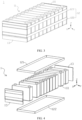
- FIG. 3 is a schematic structural diagram of the battery module in FIG. 2 in a second specific embodiment; and FIG. 4 is an exploded view of FIG. 3, FIG. 3 and FIG. 4 do not form part of the invention.
- the battery module 1 includes a plurality of battery cells 111 and a frame structure for fixing the battery cells 111, where the plurality of battery cells 111 are stacked on each other in a length direction X, and form a battery cell arrangement structure 11.
- the frame structure for fixing the battery cells 111 may include an end plate 13, and the end plate 13 is located at an end part of the battery cell arrangement structure 11 in the length direction X. Meanwhile, in a specific embodiment, the frame structure may further include a side plate (not shown), two side plates are located on two sides of the battery cell arrangement structure 11 in a width direction Y, and the side plates are connected to end plates 13, so as to form the frame structure. In this embodiment, as shown in FIG. 3 , the frame structure may not be provided with a side plate, the battery cells 111 are connected through a cable tie 12 after being stacked to form the battery cell arrangement structure 11, and in this case, end plates 13 and the cable tie 12 form the foregoing frame structure.
- FIG. 5 is a top view of the battery module in FIG. 3 ; and FIG. 6 is a sectional view of the battery module in FIG. 5 in a direction B-B.
- the end plates 13 are disposed at end parts of the battery cell arrangement structure 11 of this embodiment in the length direction X, and the end plates 13 are fixed by the cable tie 12 to form the frame structure.
- the end plate 13 of the battery module 1 when its thickness is smaller, structural strength cannot be met. Therefore, in a general case, the end plate 13 is a flat-plate structure with a certain thickness, so as to meet requirements for strength of the battery module 1. However, when the thickness of the end plate 13 is greater, energy density of the battery module 1 is affected.
- FIG. 7 is a schematic structural diagram of the end plate in FIG. 4 .
- the end plate 13 of the battery module 1 may include a first mating part 136 and a second mating part 135, where the second mating part 135 is located below the first mating part 136 in a height direction Z of the battery module 1, and a thickness of the second mating part 135 is smaller than a thickness of the first mating part 136.
- the battery module 1 is fixed in the case 2 of the battery pack M, and the battery module 1 may be mated with and fixedly connected to the box 2 through the second mating part 135.
- FIG. 8 is a side view of the end plate in FIG. 7 .
- the thicknesses of the first mating part 136 and the second mating part 135 of the end plate 13 are different, so that the end plate 13 is a structure without completely the same thickness at each position, thereby reducing a weight of the end plate 13 and improving energy density of the battery module 1 while ensuring that the end plate 13 has higher strength.
- a thickness of the end plate 13 is not completely the same thickness at each position and the battery module 1 is mounted to the box 2
- mating of the end plate 13 with another component in the box 2 could be easy to be achieved, and assembly efficiency is improved.
- FIG. 9 is a partial enlarged view of a portion III in FIG. 6 ; and FIG. 10 is a schematic diagram of relationships of various components in FIG. 9 in size.
- the thickness of the first mating part 136 is t1
- the thickness of the second mating part 135 is t2, where t1>t2>1/3t1.
- the end plate 13 has a first height L1
- the second mating part 135 has a second height L2, where L2 ⁇ 1/3L1.
- the second height L2 of the second mating part 135 with the smaller thickness should not be too great, that is, not be greater than 1/3 of the overall height of the end plate 13, thereby preventing the overall strength of the end plate 13 from being lower when the height of the second mating part 135 is too great.
- FIG. 11 is a top view of the battery pack in FIG. 2 , where the battery module is a third specific embodiment.
- a mounting beam 22 is disposed in the cavity 21 of the box 2, and in a length direction X of the battery module 1, the mounting beam 22 is located at an end part of a battery cell arrangement structure 11. Therefore, movement of the battery cell arrangement structure 11 in the length direction X could be restricted through mounting beams 22, and reliability of mounting the battery module 1 in the battery pack M could be improved. Meanwhile, the battery module 1 is mounted between two mounting beams 22, and end plates 13 are respectively close to the two mounting beams 22 and mated with the mounting beams 22.
- FIG. 12 is a sectional view in a direction C-C of FIG. 11 ;
- FIG. 13 is a partial enlarged view of a portion VI in FIG. 12 ;
- FIG. 14 is a schematic structural diagram of the end plate in FIG. 12 .
- the mounting beam 22 is mated with a second mating part 135 of a corresponding end plate 13, and in the length direction X, the second mating part 135 has a fifth bottom wall 135a, where the fifth bottom wall 135a faces the corresponding mounting beam 22, and a preset gap t is provided between the fifth bottom wall 135a and the mounting beam 22 in the length direction X.
- a range of t is t ⁇ 0.5 millimeter (mm).
- mating of the end plate 13 with the mounting beam 22 could be achieved through the second mating part 135, and by changing the thickness of the second mating part 135, the battery module 1 could be mounted between two mounting beams 22, and could be adapted to space between the mounting beams 22.
- the preset gap t is provided between the fifth bottom wall 135a of the second mating part 135 and the mounting beam 22 in the length direction X, the battery module 1 could be easily mounted between two mounting beams 22.
- the preset gap t could provide a distance by which the end plate 13 moves in the length direction X in the expansion process, and prevent the mounting beam 22 from exerting an excessively tight restraint effect on the second mating part 135 of the end plate 13 in the expansion process, thereby reducing the risk of breaking the end plate 13 caused by a difference between amounts of expansion of a first mating part 136 and the second mating part 135 with different thicknesses, and improving the service life of the end plate 13.
- the end plate 13 moves toward the mounting beam 22 in the length direction X, so that the bottom wall 135a of the second mating part 135 abuts against the mounting beam 22, the second mating part 135 receives reaction force of the mounting beam 22, and the mounting beam 22 could restrain the end plate 13 in the length direction X.
- the second mating part 135 no longer expands and deforms, while the first mating part 136 located above the second mating part 135 could expand and deform continuously. Therefore, in a direction from up to down, an amount of deformation of the end plate 13 gradually reduces from up to down.
- the end plate 13 is set to be a structure with a great thickness above (the first mating part 136) and a small thickness below (the second mating part 135), so that rigidity of the end plate 13 at the first mating part 136 is greater, and rigidity of the end plate 13 at the second mating part 135 is smaller.
- the preset gap t should not be too great or too small.
- the preset gap t is too great, in the expansion process of the battery cells 111, the distance by which the end plate 13 moves in the length direction X under the action of expansion force is greater.
- the battery module 1 includes a cable tie 12
- an amount of deformation of the cable tie 12 is greater, which results in break of the cable tie 12 before the fifth bottom wall 135a of the second mating part 135 in the end plate 13 is in contact with the mounting beam 22.
- the preset gap t is smaller, expansion space for the battery module 1 is smaller, which is not conducive to the release of the expansion force. Therefore, a size of the preset gap t could be reasonably selected by comprehensively considering factors in foregoing various aspect.
- the preset gap t may be 0.2 mm, 0.4 mm, or the like.
- FIG. 15 is a side view of the end plate in FIG. 14 .
- a step part 137 is formed between the first mating part 136 and the second mating part 135, and in a height direction Z, the mounting beam 22 abuts against the step part 137.
- a height of the second mating part 135 is equal to a height of the mounting beam 22, so that when the battery module 1 is mounted to the box 2, the step part 137 of the end plate 13 could abut against an upper surface of the mounting beam 22 in the height direction Z, so that reliability of connection between the mounting beam 22 and the end plate 13 could be improved through the support in the height direction Z provided to the end plate 13 by the mounting beam 22.
- the end plate 13 may further include a locking part 138, where the locking part 138 protrudes from the end plate 13 and extends toward the mounting beam 22. Meanwhile, as shown in FIG.
- a lower end face of the locking part 138 is flush with a step face of the step part 137, and when the battery module 1 is mounted in the box 2, the upper surface of the mounting beam 22 could abut against the step face of the step part 137 and the lower surface of the locking part 138.
- the locking part 138 may further be provided with mounting holes 138a, and the mounting hole 138a is used to be connected to the mounting beam 22.
- the mounting hole 138a may be a bolt hole, so that the end plate 13 and the mounting beam 22 can be connected by a bolt.
- the battery pack M includes a first cable tie 121 and a second cable tie 122, where the first cable tie 121 and the second cable tie 122 surround an outer side of the battery cell arrangement structure 11, where tensile strength of the first cable tie 121 is greater than tensile strength of the second cable tie 122, and an elastic modulus of the first cable tie 121 is greater than an elastic modulus of the second cable tie 122, that is, strength of the first cable tie 121 is greater than strength of the second cable tie 122, and deformability of the second cable tie 122 is greater than deformability of the first cable tie 121.
- the first cable tie 121 and the second cable tie 122 are arranged in the height direction Z of the battery module 1, and the second cable tie 122 is close to one end of the battery module 1 that is fixedly connected to the box 2, that is, the first cable tie 121 is far away from the end of the battery module 1 that is fixedly connected to the box 2, where the battery module 1 and the box 2 may be bonded specifically through an structural adhesive, or the battery module 1 may be locked to the box 2 by a bolt.
- each battery cell 111 need to be grouped by a structure with higher strength. That is, in this embodiment, the first cable tie 121 with higher tensile strength is disposed to be far away from one end of the battery module 1 that is fixedly connected to the box 2, so that the grouping of each battery cell 111 at this position is achieved through the first cable tie 121 with higher tensile strength, and grouping efficiency thereof is improved.
- the first cable tie 121 may be specifically a metal material
- the second cable tie 122 may be specifically a plastic material.
- a weight of the second cable tie 122 is smaller than a weight of the first cable tie 121.
- cable ties with different tensile strength are provided according to different strength requirements at different positions, which could achieve grouping of the battery module 1 and has higher reliability of the grouping. Meanwhile, when a second cable tie 122 with lower tensile strength is disposed at a position with a lower strength requirement, a weight of the battery module 1 could also be reduced, and energy density thereof could be improved.
- the end plate 13 is provided with a second mounting groove 132 and a third mounting groove 133, and in the height direction Z of the battery module 1, the second mounting groove 132 is located above the third mounting groove 133, where a portion of the foregoing first cable tie 121 (refer to a portion of the first cable tie 121 in the width direction) is located at the second mounting groove 132. Meanwhile, a portion of the foregoing second cable tie 122 (refer to a portion of the second cable tie 122 in the width direction) is located at the third mounting groove 133.
- FIG. 16 is a partial enlarged view of a portion IV in FIG. 9 ; and FIG. 17 is a partial enlarged view of a portion V in FIG. 9 .
- the second mounting groove 132 has a second bottom wall 132a, and when a portion of the first cable tie 121 is located at the second mounting groove 132, the first cable tie 121 abuts against the second bottom wall 132a.
- the second mounting groove 132 includes a second upper side wall 132b and a second lower side wall 132c oppositely arranged, and the first cable tie 121 is located between the second upper side wall 132b and the second lower side wall 132c. Meanwhile, the first cable tie 121 may or may not abut against the two side walls.
- the third mounting groove 133 has a third bottom wall 133a, and when a portion of the second cable tie 122 is located at the third mounting groove 133, the second cable tie 122 abuts against the third bottom wall 133a.
- the third mounting groove 133 includes a third upper side wall 133b and a third lower side wall 133c oppositely arranged, and the second cable tie 122 is located between the third upper side wall 133b and the third lower side wall 133c. Meanwhile, the second cable tie 122 may or may not abut against the two side walls.
- the second upper side wall 132b and the second lower side wall 132c of the second mounting groove 132 could restrain movement of the first cable tie 121 in the height direction Z
- the third upper side wall 133b and the third lower side wall 133c of the third mounting groove 133 could restrain movement of the second cable tie 122 in the height direction Z, thereby improving reliability of connection between the first cable tie 121 and the second cable tie 122 and the end plate 13.
- a depth of the second mounting groove 132 is T4, and a depth of the third mounting groove 133 is T5; and a thickness of the first cable tie 121 is T1, and a thickness of the second cable tie 122 is T2, where 0 ⁇ T4-T1 ⁇ 0.5 mm, and 0 ⁇ T5-T2 ⁇ 0.5 mm.
- the depth T4 of the second mounting groove 132 is greater than the thickness T1 of the first cable tie 121, and the depth T5 of the third mounting groove 133 is greater than the thickness T2 of the second cable tie 122, so that after the first cable tie 121 and the second cable tie 122 are provided, the first cable tie 121 and the second cable tie 122 do not increase a size of the battery module 1 in the length direction X, which is conducive to the spatial arrangement of the battery module 1.
- the depth T4 of the second mounting groove 132 and the depth T5 of the third mounting groove 133 should not be too great (T4-T1 ⁇ 0.5 mm, and T5-T2 ⁇ 0.5 mm), thereby avoiding the strength of the end plate 13 to be too low at positions at which the second mounting groove 132 and the third mounting groove 133 are disposed caused by the excessive depths of the second mounting groove 132 and the third mounting groove 133, and improving the service life of the end plate 13.
- the second mounting groove 132 has a first center line O1, and in the height direction Z, and a first distance H1 is provided between the first center line O1 and a lower end face 139 of the end plate 13.
- the third mounting groove 133 has a second center line O2, and in the height direction Z, a second distance H2 is provided between the second center line O2 and the lower end face 139.
- the end plate 13 has a first height L1 in the height direction Z, where H1 ⁇ 2/3L1, and 3/4L1 ⁇ H2 ⁇ 1/4L1.
- the first distance H1 could represent a set height of the second mounting groove 132 relative to the lower end face 139 of the end plate 13.
- the second distance H2 could represent a set height of the third mounting groove 133 relative to the lower end face of the end plate 13.
- One end of the battery module 1 that is close to the lower end face 139 of the end plate 13 is fixedly connected to the box 2. Therefore, a set position of the second mounting groove 132 is higher than a set position of the third mounting groove 133, that is, H1>H2.
- the thickness of the end plate 13 at each position is different, so that strength and rigidity of the end plate 13 at each position are different.
- H1 ⁇ 2/3L1 and 3/4L1 ⁇ H2 ⁇ 1/4L1 a distance between the second mounting groove 132 and the third mounting groove 133 is not too great or too small, so that after the two mounting grooves are provided, force and deformation of the end plate 13 are still relatively even.
- the end plate 13 further includes a first mating part 136 and a second mating part 135, where the second mounting groove 132 and the third mounting groove 133 are disposed at the first mating part 136, and in the height direction Z, the second mating part 135 is located below the third mounting groove 133.
- the battery module 1 and the box 2 may be bonded, and may also be connected to the mounting beam 22 through the end plate 13 and.
- the battery cell arrangement structure 11 of the battery module 1 is grouped through the first cable tie 121 and the second cable tie 122.
- the first cable tie 121 and the second cable tie 122 with different materials are arranged at intervals in the height direction Z.
- the first cable tie 121 and the second cable tie 122 with different materials are approximately at the same height, and the first cable tie 121 is located on an inner side of the second cable tie 122.
- FIG. 18 is a top view of the battery module in FIG. 2 in a first specific embodiment
- FIG. 19 is a sectional view in a direction A-A of FIG. 18
- FIG. 20 is a schematic structural diagram of a cable tie in FIG. 19 , where a first cable tie is in a slack state.
- the cable tie 12 may be specifically a band-like structure and surround an outer side of the battery cell arrangement structure 11, and the cable tie 12 includes at least a first cable tie 122 and a second cable tie 122 with different materials, where at least a portion of the first cable tie 121 is located on one side of the second cable tie 122 that is close to the battery cells 111, that is, at least a portion of the first cable tie 121 is located on an inner side of the second cable tie 122, where the inner side refers to one side close to the battery cell arrangement structure 11, and an outer side refers to one side far away from the battery cell arrangement structure 11.
- tensile strength of the first cable tie 121 may be greater than tensile strength of the second cable tie 122, where the tensile strength (or strength limit) represents a maximum stress value a material bears before being broken. Therefore, the tensile strength is greater, and bearing ability of the material is greater. That is, when the material is subjected to the same external force, it is not easy to be broken.
- strength of the first cable tie 121 located on the inner side is higher than that of the second cable tie 122.
- an elastic modulus of the first cable tie 121 is greater than an elastic modulus of the second cable tie 122.
- stress and strain of a material in an elastic deformation stage are in a proportional relationship, where a proportional coefficient of the proportional relationship is an elastic modulus, and the elastic modulus is used to measure the magnitude of ability of the material to resist elastic deformation. Therefore, the elastic modulus is greater, stress required to elastically deform the material is greater, and rigidity of the material is greater (elastic deformation is less), that is, when the stress is the same, the elastic modulus is greater, and the elastic deformation is less. Therefore, in this embodiment, the first cable tie 121 located on the inner side is less likely to elastically deform than the second cable tie 122.
- the foregoing first cable tie 121 may be a metal material
- the foregoing second cable tie 122 may be a plastic material
- the material of the first cable tie 121 may specifically be metal such as stainless steel, aluminum, or carbon steel
- the material of the second cable tie 122 may specifically be non-metal such as PET (polyester) plastic.
- PET polyethylene
- a tensile strength of the first cable tie 121 with the metal material is greater than a tensile strength of the second cable tie 122 with the plastic material.
- an elastic modulus of the first cable tie 121 with the metal material is greater than an elastic modulus of the second cable tie 122 with the plastic material.
- FIG. 21 is a partial enlarged view of a portion I in FIG. 19 in an embodiment
- FIG. 22 is a partial enlarged view of a portion I in FIG. 19 in another embodiment.
- the first cable tie 121 has a first width W1
- the second cable tie 122 has a second width W2.
- the first cable tie 121 has three sizes of length, width and thickness.
- a size with the largest value represents the length of the first cable tie 121 (that is, a circumference of the first cable tie 121)
- a size with the smallest value represents the thickness of the first cable tie 121
- a size with a value between the largest value and the smallest value represents the width of the first cable tie 121.
- the first width W1 of the first cable tie 121 refers to a size in the height direction Z of the battery module 1.
- W1 ⁇ W2 that is, the width of the first cable tie 121 is smaller than or equal to the width of the second cable tie 122.
- an abutment height of the second cable tie 122 and the first cable tie 121 is W3, where W3 ⁇ 1 2 W1 , that is, the abutment height of the first cable tie 121 and the second cable tie 122 is greater than or equal to half of the width of the one with a smaller width.
- the end plates 13 of the battery module 1 are located at two ends of the battery cell arrangement structure 11 in the length direction X, and the two end plates 13 and the battery cell arrangement structure 11 are fastened through the cable tie 12. Specifically, as shown in FIG. 21 and FIG.
- the end plate 13 is provided with a first mounting groove 131, and in the height direction Z, a portion of the first cable tie 121 (referring to a portion of the first cable tie 121 in the width direction) and a portion of the second cable tie 122 (referring to a portion of the second cable tie 122 in the width direction) are located at the first mounting groove 131, and the first cable tie 121 at least partially abuts against the second cable tie 122 in the mounting groove 131.
- a depth of the first mounting groove 131 is T3
- a thickness of the first cable tie 121 is T1
- a thickness of the second cable tie 122 is T2, where T1+T2 ⁇ T3 ⁇ T1+T2+1 mm.
- FIG. 23 is a top view of FIG. 20 ; and FIG. 24 is a partial enlarged view of a portion II in FIG. 23 .
- the first cable tie 121 located on the inner side may further include a bending structure 121c. Therefore, when the first cable tie 121 receives force, the bending structure 121c could deform.
- FIG. 25 is an exploded view of FIG. 20 .
- the first cable tie 121 may be an annular wave structure, that is, the first cable tie 121 may include a plurality of foregoing bending structures 121c, and bending directions of at least two bending structures 121c are opposite. Meanwhile, each bending structure 121c is an arc structure, an arc is used to transition between adjacent bending structures 121c, so as to form the first cable tie 121 in the wave structure.
- the wave structure of the first cable tie 121 may be formed by stamping in a processing process.
- the first cable tie 121 and the second cable tie 122 are annular structures that could surround the battery cell arrangement structure 11, and the two are shaped into annular structures through a band-like structure.
- the first cable tie 121 is formed by a first tape body 121a, two end parts of the first tape body 121a are connected, which could form the first cable tie 121, and a first connecting region 121b is formed at the connections, where the two connections of the first cable tie 121a could surround the battery cell arrangement structure 11 after they need to meet the connection to form the first cable tie 121.
- the second cable tie 122 is formed by a second tape body 122a, two end parts of the second tape body 122a are connected, which could form the second cable tie 122, and a second connecting region 122b is formed at the connections, where the two connections of the second cable tie 122b could surround the battery cell arrangement structure 11 after they need to meet the connection to form the second cable tie 122.
- FIG. 26 is a schematic structural diagram of a cable tie in FIG. 19 , where a first cable tie is in a tight state.
- a length of the first cable tie 121 is greater than a circumference of the battery cell arrangement structure 11, and the length of the first cable tie 121 is greater than a length of a second cable tie 122.
- the length of the first cable tie 121 in an annular structure refers to a circumference of the first cable tie 121.
- FIG. 27 is a partial enlarged view of a portion VII in FIG. 13 .
- the following embodiments are not according to the invention and are present for illustration purposes only.
- the battery pack M may further include a third cable tie 123, and in the height direction Z, the third cable tie 123 surrounds an upper part of the battery cell arrangement structure 11 that is far away from the mounting beam 22.
- the battery module 1 when the expansion of the battery cells 111 of the battery module 1 allows the end plates 13 to move close to the mounting beams 22, two mounting beams 22 could play a role of restraining the end plate 13 through the second mating part 135, thereby improving reliability of grouping of the battery module 1 at the position corresponding to the mounting beam 22.
- the battery module 1 may further be provided with the third cable tie 123, and through the third cable tie 123 and the mounting beams 22, the battery cell arrangement structure 11 could be restrained in the height direction Z, and reliability of grouping of the battery cells 111 could be improved.
- the end plate 13 is provided with a fourth mounting groove 134, and in the height direction Z, a portion of the third cable tie 123 (refer to a portion of the third cable tie 123 in the width direction) is located at the fourth mounting groove 134.
- the fourth mounting groove 134 in the length direction X, has a fourth bottom wall 134a, and when a portion of the third cable tie 123 is located at the fourth mounting groove 134, the third cable tie 123 abuts against the fourth bottom wall 134a in the length direction X.
- the fourth mounting groove 134 has a fourth upper side wall 134b and a fourth lower side wall 134c oppositely arranged, and in the height direction X, a portion of the third cable tie 123 is located between the fourth upper side wall 134b and the fourth lower side wall 134c.
- the third cable tie 123 may abut against both the fourth upper side wall 134b and the fourth lower side wall 134c, or the third cable tie 123 may not abut against at least one side wall of the fourth mounting groove 134. In the embodiment shown in FIG. 27 , in the height direction Z, the third cable tie 123 does not abut against the fourth upper side wall 134b and the fourth lower side wall 134c.
- the fourth upper side wall 134b and the fourth lower side wall 134c of the fourth mounting groove 134 could restrain movement of the third cable tie 123 in the height direction Z, thereby improving reliability of connection between the third cable tie 123 and the end plate 13.
- the third cable tie 123 has a sixth thickness T6, and a depth of the fourth mounting groove 134 is T7, where 0 ⁇ T7-T6 ⁇ 0.5 mm.
- the depth T7 of the fourth mounting groove 134 is greater than the sixth thickness T6 of the third cable tie 123, so that after the third cable tie 123 is provided, the third cable tie 123 does not increase a size of the battery module 1 in the length direction X, which is conducive to the spatial arrangement of the battery module 1. Meanwhile, the depth of the fourth mounting groove 134 should not be too great (T7-T6 ⁇ 0.5 mm), thereby avoiding the strength of the end plate 13 to be too low at a the position at which the fourth mounting groove 134 is disposed caused by the excessive depth of the fourth mounting groove 134, and improving the service life of the end plate 13.
Landscapes
- Chemical & Material Sciences (AREA)
- Chemical Kinetics & Catalysis (AREA)
- Electrochemistry (AREA)
- General Chemical & Material Sciences (AREA)
- Engineering & Computer Science (AREA)
- Aviation & Aerospace Engineering (AREA)
- Manufacturing & Machinery (AREA)
- Battery Mounting, Suspending (AREA)
Description
- The present application relates to the technical field of energy storage devices, and in particular, to a battery pack and an apparatus
- A battery module includes battery cells and a frame structure, where the frame structure encloses a cavity, the battery cells are stacked in the cavity in a length direction, the frame structure includes an end plate, and the end plate is located at an end part of the battery cells in the length direction for restricting movement of the battery cells in the length direction. At present, in order to improve energy density of the battery module, a weight of the frame structure should be reduced as much as possible, that is, a weight of the end plate shall be reduced as much as possible on the premise that the end plate is ensured to have sufficient strength.
-
EP2735041A1 discloses a power supply unit for an electric vehicle comprising a tray and at least one battery module fixed on the tray via a strip. Each battery module comprises: a housing having a bottom plate mounted onto the tray and first to fourth side plates disposed on the bottom plate, wherein the first and third side plates are opposed to each other in a thickness direction and the second and fourth side plates are opposed to each other in a front-rear direction; a battery pack, disposed in the housing, having a plurality of cells arranged along the thickness direction; and flexible members disposed between the first and third side plates and the battery pack respectively, for fastening the battery pack. -
CN109273752A discloses a new energy source cylindrical battery module composition group structure, which mainly fixes battery modules into groups, and the whole module composition group structure is composed of a battery module, a packing belt fixing plate and a packing belt, the battery modules are compressed through the packing belt retightening, and the requirements of battery module structure design and electric performance parameters are met. -
JP2010244894A - The invention is set out in the appended set of claims.
-
-
FIG. 1 is a schematic structural diagram of an apparatus provided in the present application in a specific embodiment; -
FIG. 2 is a schematic diagram of a partial structure of a battery pack provided in the present application in a specific embodiment; -
FIG. 3 is a schematic structural diagram of a battery module inFIG. 2 in a second specific embodiment; -
FIG. 4 is an exploded view ofFIG. 3 ; -
FIG. 5 is a top view of the battery module inFIG. 3 ; -
FIG. 6 is a sectional view of the battery module inFIG. 5 in a direction B-B; -
FIG. 7 is a schematic structural diagram of an end plate inFIG. 4 ; -
FIG. 8 is a side view of the end plate inFIG. 7 ; -
FIG. 9 is a partial enlarged view of a portion III inFIG. 6 ; -
FIG. 10 is a schematic diagram of relationships of various components inFIG. 9 in size; -
FIG. 11 is a top view of the battery pack inFIG. 2 , where a battery module is a third specific embodiment; -
FIG. 12 is a sectional view in a direction C-C ofFIG. 11 ; -
FIG. 13 is a partial enlarged view of a portion VI inFIG. 12 ; -
FIG. 14 is a schematic structural diagram of an end plate inFIG. 12 ; -
FIG. 15 is a side view of the end plate inFIG. 14 ; -
FIG. 16 is a partial enlarged view of a portion IV inFIG. 9 ; -
FIG. 17 is a partial enlarged view of a portion V inFIG. 9 ; -
FIG. 18 is a top view of a battery module inFIG. 2 in a first specific embodiment; -
FIG. 19 is a sectional view in a direction A-A ofFIG. 18 ; -
FIG. 20 is a schematic structural diagram of a cable tie inFIG. 19 , where a first cable tie is in a slack state; -
FIG. 21 is a partial enlarged view of a portion I inFIG. 19 in an embodiment; -
FIG. 22 is a partial enlarged view of a portion I inFIG. 19 in another embodiment; -
FIG. 23 is a top view of the cable tie inFIG. 20 ; -
FIG. 24 is a partial enlarged view of a portion II inFIG. 23 ; -
FIG. 25 is an exploded view of the cable tie inFIG. 20 ; -
FIG. 26 is a schematic structural diagram of a cable tie inFIG. 19 , where a first cable tie is in a tight state; and -
FIG. 27 is a partial enlarged view of a portion VII inFIG. 13 . - The embodiments of
Figures 11-15 and18-27 as well as the passages of the description referring thereto do not form part of claimed invention. -
- D-apparatus; M-battery pack;
- 1-battery module;
- 11-battery cell arrangement structure; 111-battery cell;
- 12-cable tie; 121-first cable tie; 121a-first tape body; 121b-first connecting region; 121c-bending structure; 122-second cable tie; 122a-second tape body; 122b-second connecting region; 123-third cable tie;
- 13-end plate; 13 1 -first mounting groove; 131a-first bottom wall; 131b-first upper side wall; 131c-first lower side wall; 132-second mounting groove; 132a-second bottom wall;132b-second upper side wall; 132c-second lower side wall; 133-third mounting groove; 133a-third bottom wall;133b-third upper side wall; 133c-third lower side wall; 134-fourth mounting groove; 134a-fourth bottom wall; 134b-fourth upper side wall; 134c-fourth lower side wall; 135-mating part; 135a-a fifth bottom wall; 136-body part; 137-step part; 138-locking part; 138a-mounting hole; 139-lower end face;
- 2-box; 21-cavity; 22-mounting beam.
- The accompanying drawings here, which are incorporated into the specification and constitute part of this specification, illustrate embodiments that comply with the present application, and are used to interpret the principle of the present application together with the specification.
- To understand technical solutions of the present application better, embodiments of the present application will be described in detail below with reference to the accompanying drawings. The following explanations are not according to the invention and are present for illustration purposes only.
- It should be noted that the described embodiments are merely a part, but not all, of the embodiments of the present application. All of other embodiments obtained by those of ordinary skill in the art based on the embodiments of the present application without any inventive effort shall fall within the protection scope of the present application.
- Terms used in the embodiments of the present application are merely for the purpose of describing particular embodiments, and are not intended to limit the present application. The use of singular forms of "a", "the" and "said" in the embodiments of the present application and the claims appended hereto is also intended to include a plural form, unless otherwise clearly indicated herein by context.
- It should be understood that the term "and/or" used herein merely describes association relations between associated objects, and expresses three relations, for example, A and/or B may express three conditions, namely A exists separately, A and B exist simultaneously, and B exists separately. In addition, the character "/" herein generally indicates an "or" relationship between associated objects before and after the character.
- It should be noted that the terms representing directions such as "up", "down", "left" and "right" described in the embodiments of the present application are described from the angles shown in the accompanying drawings, and should not be understood as a limitation on the embodiments of the present application. In addition, in the context, it should also be understood that when it is mentioned that an element is connected "on" or "under" another element, it can not only be directly connected "on" or "under" another element, but also be indirectly connected "on" or "under" another element through an intermediate element.
-
FIG. 1 is a schematic structural diagram of an apparatus provided in the present application in a specific embodiment, which does not form part of the invention. - As shown in
FIG. 1 , an embodiment of the present application provides an apparatus D in whichbattery cells 111 are used as a power supply, a battery pack M and a battery module 1 (refer toFIG. 2 ), where the apparatus D in which thebattery cells 111 are used as the power supply includes mobile devices such as vehicles, ships, and light aeroplanes, andFIG. 1 shows a schematic diagram in which the apparatus D is a vehicle. The apparatus D includes a power source for providing driving force for the apparatus D, and the power source may be configured as abattery module 1 providing electric energy for the apparatus D. The driving force of the apparatus D may be all electric energy, or may include energy and another energy source (such as mechanical energy). The power source may be the battery module 1 (or the battery pack M), or the power source may be the battery module 1 (or the battery pack M), an engine, and the like. Therefore, any apparatus D in whichbattery cells 111 are used as a power supply is within the protection scope of the present application. -
FIG. 2 is a schematic diagram of a partial structure of a battery pack provided in the present application in a specific embodiment, which does not form part of the invention. - As shown in
FIG. 2 , a battery pack M includes acase 2 and abattery module 1 of the present application, where thecase 2 has acavity 21, thebattery module 1 is housed in thecavity 21, and one ormore battery modules 1 are arranged in thecavity 21. -
FIG. 3 is a schematic structural diagram of the battery module inFIG. 2 in a second specific embodiment; andFIG. 4 is an exploded view ofFIG. 3, FIG. 3 and FIG. 4 do not form part of the invention. - More specifically, as shown in
FIG. 3 and FIG. 4 , thebattery module 1 includes a plurality ofbattery cells 111 and a frame structure for fixing thebattery cells 111, where the plurality ofbattery cells 111 are stacked on each other in a length direction X, and form a battery cell arrangement structure 11. - The frame structure for fixing the
battery cells 111 may include anend plate 13, and theend plate 13 is located at an end part of the battery cell arrangement structure 11 in the length direction X. Meanwhile, in a specific embodiment, the frame structure may further include a side plate (not shown), two side plates are located on two sides of the battery cell arrangement structure 11 in a width direction Y, and the side plates are connected to endplates 13, so as to form the frame structure. In this embodiment, as shown inFIG. 3 , the frame structure may not be provided with a side plate, thebattery cells 111 are connected through acable tie 12 after being stacked to form the battery cell arrangement structure 11, and in this case,end plates 13 and thecable tie 12 form the foregoing frame structure. -
FIG. 5 is a top view of the battery module inFIG. 3 ; andFIG. 6 is a sectional view of the battery module inFIG. 5 in a direction B-B. - As shown in
FIG. 5 and FIG. 6 , theend plates 13 are disposed at end parts of the battery cell arrangement structure 11 of this embodiment in the length direction X, and theend plates 13 are fixed by thecable tie 12 to form the frame structure. - For the
end plate 13 of thebattery module 1, when its thickness is smaller, structural strength cannot be met. Therefore, in a general case, theend plate 13 is a flat-plate structure with a certain thickness, so as to meet requirements for strength of thebattery module 1. However, when the thickness of theend plate 13 is greater, energy density of thebattery module 1 is affected. -
FIG. 7 is a schematic structural diagram of the end plate inFIG. 4 . - To solve the foregoing technical problem, as shown in
FIG. 7 , theend plate 13 of thebattery module 1 may include afirst mating part 136 and asecond mating part 135, where thesecond mating part 135 is located below thefirst mating part 136 in a height direction Z of thebattery module 1, and a thickness of thesecond mating part 135 is smaller than a thickness of thefirst mating part 136. Meanwhile, thebattery module 1 is fixed in thecase 2 of the battery pack M, and thebattery module 1 may be mated with and fixedly connected to thebox 2 through thesecond mating part 135. -
FIG. 8 is a side view of the end plate inFIG. 7 . - As shown in
FIG. 8 , in this embodiment, the thicknesses of thefirst mating part 136 and thesecond mating part 135 of theend plate 13 are different, so that theend plate 13 is a structure without completely the same thickness at each position, thereby reducing a weight of theend plate 13 and improving energy density of thebattery module 1 while ensuring that theend plate 13 has higher strength. In addition, when a thickness of theend plate 13 is not completely the same thickness at each position and thebattery module 1 is mounted to thebox 2, mating of theend plate 13 with another component in thebox 2 could be easy to be achieved, and assembly efficiency is improved. -
FIG. 9 is a partial enlarged view of a portion III inFIG. 6 ; andFIG. 10 is a schematic diagram of relationships of various components inFIG. 9 in size. - Specifically, as shown in
FIG. 9 and FIG. 10 , the thickness of thefirst mating part 136 is t1, and the thickness of thesecond mating part 135 is t2, where t1>t2>1/3t1. - In this embodiment, when t1>t2, rigidity of the
first mating part 136 is greater than rigidity of thesecond mating part 135, and when t2>1/3t1, a difference between the rigidity of thefirst mating part 136 and the rigidity of thesecond mating part 135 is not too great, so as to reduce the risk of breaking theend plate 13 between thefirst mating part 136 and themating part 135 under the action of expansion force due to a great difference between amounts of deformation of the two. - More specifically, as shown in
FIG. 10 , in the height direction Z, theend plate 13 has a first height L1, and thesecond mating part 135 has a second height L2, where L2≤1/3L1. - In this embodiment, the second height L2 of the
second mating part 135 with the smaller thickness should not be too great, that is, not be greater than 1/3 of the overall height of theend plate 13, thereby preventing the overall strength of theend plate 13 from being lower when the height of thesecond mating part 135 is too great. -
FIG. 11 is a top view of the battery pack inFIG. 2 , where the battery module is a third specific embodiment. - Specifically, as shown in
FIG. 11 , a mountingbeam 22 is disposed in thecavity 21 of thebox 2, and in a length direction X of thebattery module 1, the mountingbeam 22 is located at an end part of a battery cell arrangement structure 11. Therefore, movement of the battery cell arrangement structure 11 in the length direction X could be restricted through mountingbeams 22, and reliability of mounting thebattery module 1 in the battery pack M could be improved. Meanwhile, thebattery module 1 is mounted between two mountingbeams 22, andend plates 13 are respectively close to the two mountingbeams 22 and mated with the mounting beams 22. -
FIG. 12 is a sectional view in a direction C-C ofFIG. 11 ;FIG. 13 is a partial enlarged view of a portion VI inFIG. 12 ; andFIG. 14 is a schematic structural diagram of the end plate inFIG. 12 . - Specifically, as shown in
FIG. 12 ,FIG. 13 and FIG. 14 , the mountingbeam 22 is mated with asecond mating part 135 of acorresponding end plate 13, and in the length direction X, thesecond mating part 135 has a fifth bottom wall 135a, where the fifth bottom wall 135a faces the corresponding mountingbeam 22, and a preset gap t is provided between the fifth bottom wall 135a and the mountingbeam 22 in the length direction X. A range of t is t<0.5 millimeter (mm). - In this embodiment, mating of the
end plate 13 with the mountingbeam 22 could be achieved through thesecond mating part 135, and by changing the thickness of thesecond mating part 135, thebattery module 1 could be mounted between two mountingbeams 22, and could be adapted to space between the mounting beams 22. In addition, when the preset gap t is provided between the fifth bottom wall 135a of thesecond mating part 135 and the mountingbeam 22 in the length direction X, thebattery module 1 could be easily mounted between two mountingbeams 22. Meanwhile, whenbattery cells 111 of thebattery module 1 expand in the length direction X, the preset gap t could provide a distance by which theend plate 13 moves in the length direction X in the expansion process, and prevent the mountingbeam 22 from exerting an excessively tight restraint effect on thesecond mating part 135 of theend plate 13 in the expansion process, thereby reducing the risk of breaking theend plate 13 caused by a difference between amounts of expansion of afirst mating part 136 and thesecond mating part 135 with different thicknesses, and improving the service life of theend plate 13. - In addition, after the
battery cells 111 in thebattery module 1 expand, theend plate 13 moves toward the mountingbeam 22 in the length direction X, so that the bottom wall 135a of thesecond mating part 135 abuts against the mountingbeam 22, thesecond mating part 135 receives reaction force of the mountingbeam 22, and the mountingbeam 22 could restrain theend plate 13 in the length direction X. Meanwhile, when thebattery cells 111 expand continuously, due to the restraint action of the mountingbeam 22, thesecond mating part 135 no longer expands and deforms, while thefirst mating part 136 located above thesecond mating part 135 could expand and deform continuously. Therefore, in a direction from up to down, an amount of deformation of theend plate 13 gradually reduces from up to down. Therefore, theend plate 13 is set to be a structure with a great thickness above (the first mating part 136) and a small thickness below (the second mating part 135), so that rigidity of theend plate 13 at thefirst mating part 136 is greater, and rigidity of theend plate 13 at thesecond mating part 135 is smaller. - The preset gap t should not be too great or too small. When the preset gap t is too great, in the expansion process of the
battery cells 111, the distance by which theend plate 13 moves in the length direction X under the action of expansion force is greater. When thebattery module 1 includes acable tie 12, an amount of deformation of thecable tie 12 is greater, which results in break of thecable tie 12 before the fifth bottom wall 135a of thesecond mating part 135 in theend plate 13 is in contact with the mountingbeam 22. When the preset gap t is smaller, expansion space for thebattery module 1 is smaller, which is not conducive to the release of the expansion force. Therefore, a size of the preset gap t could be reasonably selected by comprehensively considering factors in foregoing various aspect. For example, the preset gap t may be 0.2 mm, 0.4 mm, or the like. -
FIG. 15 is a side view of the end plate inFIG. 14 . - As shown in
FIG. 13 andFIG. 15 , astep part 137 is formed between thefirst mating part 136 and thesecond mating part 135, and in a height direction Z, the mountingbeam 22 abuts against thestep part 137. - Therefore, in this embodiment, a height of the
second mating part 135 is equal to a height of the mountingbeam 22, so that when thebattery module 1 is mounted to thebox 2, thestep part 137 of theend plate 13 could abut against an upper surface of the mountingbeam 22 in the height direction Z, so that reliability of connection between the mountingbeam 22 and theend plate 13 could be improved through the support in the height direction Z provided to theend plate 13 by the mountingbeam 22. Further, as shown inFIG. 14 andFIG. 15 , theend plate 13 may further include a lockingpart 138, where the lockingpart 138 protrudes from theend plate 13 and extends toward the mountingbeam 22. Meanwhile, as shown inFIG. 15 , a lower end face of the lockingpart 138 is flush with a step face of thestep part 137, and when thebattery module 1 is mounted in thebox 2, the upper surface of the mountingbeam 22 could abut against the step face of thestep part 137 and the lower surface of the lockingpart 138. Meanwhile, the lockingpart 138 may further be provided with mounting holes 138a, and the mounting hole 138a is used to be connected to the mountingbeam 22. Specifically, the mounting hole 138a may be a bolt hole, so that theend plate 13 and the mountingbeam 22 can be connected by a bolt. - In another possible design, in the embodiment shown in
FIG. 3 and FIG. 4 , the battery pack M includes afirst cable tie 121 and asecond cable tie 122, where thefirst cable tie 121 and thesecond cable tie 122 surround an outer side of the battery cell arrangement structure 11, where tensile strength of thefirst cable tie 121 is greater than tensile strength of thesecond cable tie 122, and an elastic modulus of thefirst cable tie 121 is greater than an elastic modulus of thesecond cable tie 122, that is, strength of thefirst cable tie 121 is greater than strength of thesecond cable tie 122, and deformability of thesecond cable tie 122 is greater than deformability of thefirst cable tie 121. Based on this, thefirst cable tie 121 and thesecond cable tie 122 are arranged in the height direction Z of thebattery module 1, and thesecond cable tie 122 is close to one end of thebattery module 1 that is fixedly connected to thebox 2, that is, thefirst cable tie 121 is far away from the end of thebattery module 1 that is fixedly connected to thebox 2, where thebattery module 1 and thebox 2 may be bonded specifically through an structural adhesive, or thebattery module 1 may be locked to thebox 2 by a bolt. - In this embodiment, in the height direction Z, one end of the
battery module 1 is fixedly connected to thebox 2. Therefore, at this position, reliability of grouping of eachbattery cell 111 is higher, and only asecond cable tie 122 with lower tensile strength is required to be provided, the reliable grouping can be achieved. For one end of thebattery module 1 that is not connected to thebox 2, eachbattery cell 111 need to be grouped by a structure with higher strength. That is, in this embodiment, thefirst cable tie 121 with higher tensile strength is disposed to be far away from one end of thebattery module 1 that is fixedly connected to thebox 2, so that the grouping of eachbattery cell 111 at this position is achieved through thefirst cable tie 121 with higher tensile strength, and grouping efficiency thereof is improved. - Meanwhile, when the
battery cells 111 of thebattery module 1 expand, a position of the battery cell arrangement structure 11 that is far away from one end connected to thebox 2 expands and deforms to be large. Therefore, when thefirst cable tie 121 with higher tensile strength is disposed at this position, the risk of breaking thefirst cable tie 121 under the action of expansion force could be reduced. - The
first cable tie 121 may be specifically a metal material, and thesecond cable tie 122 may be specifically a plastic material. For afirst cable tie 121 and asecond cable tie 122 with the same volume, a weight of thesecond cable tie 122 is smaller than a weight of thefirst cable tie 121. - Therefore, in this embodiment, cable ties with different tensile strength are provided according to different strength requirements at different positions, which could achieve grouping of the
battery module 1 and has higher reliability of the grouping. Meanwhile, when asecond cable tie 122 with lower tensile strength is disposed at a position with a lower strength requirement, a weight of thebattery module 1 could also be reduced, and energy density thereof could be improved. - Specifically, as shown in
FIG. 7 and FIG. 8 , theend plate 13 is provided with asecond mounting groove 132 and athird mounting groove 133, and in the height direction Z of thebattery module 1, the second mountinggroove 132 is located above the third mountinggroove 133, where a portion of the foregoing first cable tie 121 (refer to a portion of thefirst cable tie 121 in the width direction) is located at the second mountinggroove 132. Meanwhile, a portion of the foregoing second cable tie 122 (refer to a portion of thesecond cable tie 122 in the width direction) is located at the third mountinggroove 133. -
FIG. 16 is a partial enlarged view of a portion IV inFIG. 9 ; andFIG. 17 is a partial enlarged view of a portion V inFIG. 9 . - Specifically, as shown in
FIG. 16 andFIG. 17 , in the length direction X of thebattery module 1, the second mountinggroove 132 has a second bottom wall 132a, and when a portion of thefirst cable tie 121 is located at the second mountinggroove 132, thefirst cable tie 121 abuts against the second bottom wall 132a. Meanwhile, in the height direction Z, the second mountinggroove 132 includes a secondupper side wall 132b and a secondlower side wall 132c oppositely arranged, and thefirst cable tie 121 is located between the secondupper side wall 132b and the secondlower side wall 132c. Meanwhile, thefirst cable tie 121 may or may not abut against the two side walls. Similarly, in the length direction X of thebattery module 1, the third mountinggroove 133 has a third bottom wall 133a, and when a portion of thesecond cable tie 122 is located at the third mountinggroove 133, thesecond cable tie 122 abuts against the third bottom wall 133a. Meanwhile, in the height direction Z, the third mountinggroove 133 includes a thirdupper side wall 133b and a thirdlower side wall 133c oppositely arranged, and thesecond cable tie 122 is located between the thirdupper side wall 133b and the thirdlower side wall 133c. Meanwhile, thesecond cable tie 122 may or may not abut against the two side walls. - In this embodiment, by disposing the second mounting
groove 132 and the third mountinggroove 133 on theend plate 13, the secondupper side wall 132b and the secondlower side wall 132c of the second mountinggroove 132 could restrain movement of thefirst cable tie 121 in the height direction Z, and the thirdupper side wall 133b and the thirdlower side wall 133c of the third mountinggroove 133 could restrain movement of thesecond cable tie 122 in the height direction Z, thereby improving reliability of connection between thefirst cable tie 121 and thesecond cable tie 122 and theend plate 13. - As shown in
FIG. 16 andFIG. 17 , in the length direction X, a depth of the second mountinggroove 132 is T4, and a depth of the third mountinggroove 133 is T5; and a thickness of thefirst cable tie 121 is T1, and a thickness of thesecond cable tie 122 is T2, where 0<T4-T1<0.5 mm, and 0<T5-T2<0.5 mm. - In this embodiment, the depth T4 of the second mounting
groove 132 is greater than the thickness T1 of thefirst cable tie 121, and the depth T5 of the third mountinggroove 133 is greater than the thickness T2 of thesecond cable tie 122, so that after thefirst cable tie 121 and thesecond cable tie 122 are provided, thefirst cable tie 121 and thesecond cable tie 122 do not increase a size of thebattery module 1 in the length direction X, which is conducive to the spatial arrangement of thebattery module 1. Meanwhile, the depth T4 of the second mountinggroove 132 and the depth T5 of the third mountinggroove 133 should not be too great (T4-T1<0.5 mm, and T5-T2<0.5 mm), thereby avoiding the strength of theend plate 13 to be too low at positions at which the second mountinggroove 132 and the third mountinggroove 133 are disposed caused by the excessive depths of the second mountinggroove 132 and the third mountinggroove 133, and improving the service life of theend plate 13. - More specifically, as shown in
FIG. 10 , in the height direction X, the second mountinggroove 132 has a first center line O1, and in the height direction Z, and a first distance H1 is provided between the first center line O1 and alower end face 139 of theend plate 13. Similarly, in the height direction X, the third mountinggroove 133 has a second center line O2, and in the height direction Z, a second distance H2 is provided between the second center line O2 and thelower end face 139. Meanwhile, theend plate 13 has a first height L1 in the height direction Z, where H1≥2/3L1, and 3/4L1≥H2≥1/4L1. - In this embodiment, the first distance H1 could represent a set height of the second mounting
groove 132 relative to thelower end face 139 of theend plate 13. Similarly, the second distance H2 could represent a set height of the third mountinggroove 133 relative to the lower end face of theend plate 13. One end of thebattery module 1 that is close to thelower end face 139 of theend plate 13 is fixedly connected to thebox 2. Therefore, a set position of the second mountinggroove 132 is higher than a set position of the third mountinggroove 133, that is, H1>H2. - Meanwhile, after the second mounting
groove 132 and the third mountinggroove 133 arranged in the height direction Z are disposed on theend plate 13, the thickness of theend plate 13 at each position is different, so that strength and rigidity of theend plate 13 at each position are different. When H1≥2/3L1 and 3/4L1≥H2≥1/4L1, a distance between the second mountinggroove 132 and the third mountinggroove 133 is not too great or too small, so that after the two mounting grooves are provided, force and deformation of theend plate 13 are still relatively even. - In addition, in the embodiment shown in
FIG. 8 , theend plate 13 further includes afirst mating part 136 and asecond mating part 135, where the second mountinggroove 132 and the third mountinggroove 133 are disposed at thefirst mating part 136, and in the height direction Z, thesecond mating part 135 is located below the third mountinggroove 133. In this case, thebattery module 1 and thebox 2 may be bonded, and may also be connected to the mountingbeam 22 through theend plate 13 and. Meanwhile, the battery cell arrangement structure 11 of thebattery module 1 is grouped through thefirst cable tie 121 and thesecond cable tie 122. - To sum up, in this embodiment, the
first cable tie 121 and thesecond cable tie 122 with different materials are arranged at intervals in the height direction Z. However, in other embodiments, thefirst cable tie 121 and thesecond cable tie 122 with different materials are approximately at the same height, and thefirst cable tie 121 is located on an inner side of thesecond cable tie 122. -
FIG. 18 is a top view of the battery module inFIG. 2 in a first specific embodiment;FIG. 19 is a sectional view in a direction A-A ofFIG. 18 ; andFIG. 20 is a schematic structural diagram of a cable tie inFIG. 19 , where a first cable tie is in a slack state. - Specifically, as shown in
FIG. 18 ,FIG. 19 and FIG. 20 , thecable tie 12 may be specifically a band-like structure and surround an outer side of the battery cell arrangement structure 11, and thecable tie 12 includes at least afirst cable tie 122 and asecond cable tie 122 with different materials, where at least a portion of thefirst cable tie 121 is located on one side of thesecond cable tie 122 that is close to thebattery cells 111, that is, at least a portion of thefirst cable tie 121 is located on an inner side of thesecond cable tie 122, where the inner side refers to one side close to the battery cell arrangement structure 11, and an outer side refers to one side far away from the battery cell arrangement structure 11. - Specifically, tensile strength of the
first cable tie 121 may be greater than tensile strength of thesecond cable tie 122, where the tensile strength (or strength limit) represents a maximum stress value a material bears before being broken. Therefore, the tensile strength is greater, and bearing ability of the material is greater. That is, when the material is subjected to the same external force, it is not easy to be broken. In this embodiment, strength of thefirst cable tie 121 located on the inner side is higher than that of thesecond cable tie 122. - Meanwhile, an elastic modulus of the
first cable tie 121 is greater than an elastic modulus of thesecond cable tie 122. According to Hooke's Law, stress and strain of a material in an elastic deformation stage are in a proportional relationship, where a proportional coefficient of the proportional relationship is an elastic modulus, and the elastic modulus is used to measure the magnitude of ability of the material to resist elastic deformation. Therefore, the elastic modulus is greater, stress required to elastically deform the material is greater, and rigidity of the material is greater (elastic deformation is less), that is, when the stress is the same, the elastic modulus is greater, and the elastic deformation is less. Therefore, in this embodiment, thefirst cable tie 121 located on the inner side is less likely to elastically deform than thesecond cable tie 122. - More specifically, the foregoing
first cable tie 121 may be a metal material, and the foregoingsecond cable tie 122 may be a plastic material. For example, the material of thefirst cable tie 121 may specifically be metal such as stainless steel, aluminum, or carbon steel, and the material of thesecond cable tie 122 may specifically be non-metal such as PET (polyester) plastic. It can be understood that a tensile strength of thefirst cable tie 121 with the metal material is greater than a tensile strength of thesecond cable tie 122 with the plastic material. Meanwhile, an elastic modulus of thefirst cable tie 121 with the metal material is greater than an elastic modulus of thesecond cable tie 122 with the plastic material. In a possible design, as shown inFIG. 20 , in the height direction Z of thebattery module 1, at least a portion of thefirst cable tie 121 abuts against thesecond cable tie 122, that is, in the height direction Z, there is an overlap between thefirst cable tie 121 and thesecond cable tie 122, and the two abut against each other at the overlapping position. When there is relative movement between thefirst cable tie 121 and thesecond cable tie 122, there is frictional resistance at the position where the two abut against each other, thereby reducing tendency of the relative movement of the two. -
FIG. 21 is a partial enlarged view of a portion I inFIG. 19 in an embodiment; andFIG. 22 is a partial enlarged view of a portion I inFIG. 19 in another embodiment. - Specifically, as shown in
FIG. 21 and FIG. 22 , thefirst cable tie 121 has a first width W1, and thesecond cable tie 122 has a second width W2. In an example of thefirst cable tie 121, thefirst cable tie 121 has three sizes of length, width and thickness. In thefirst cable tie 121 in a band-like structure, a size with the largest value represents the length of the first cable tie 121 (that is, a circumference of the first cable tie 121), a size with the smallest value represents the thickness of thefirst cable tie 121, and a size with a value between the largest value and the smallest value represents the width of thefirst cable tie 121. Based on the angles of view shown inFIG. 21 and FIG. 22 , the first width W1 of thefirst cable tie 121 refers to a size in the height direction Z of thebattery module 1. - In a specific embodiment, W1≤W2, that is, the width of the
first cable tie 121 is smaller than or equal to the width of thesecond cable tie 122. In the height direction Z, an abutment height of thesecond cable tie 122 and thefirst cable tie 121 is W3, where
first cable tie 121 and thesecond cable tie 122 is greater than or equal to half of the width of the one with a smaller width. - In a possible design, as shown in
FIGS. 18 to 22 , theend plates 13 of thebattery module 1 are located at two ends of the battery cell arrangement structure 11 in the length direction X, and the twoend plates 13 and the battery cell arrangement structure 11 are fastened through thecable tie 12. Specifically, as shown inFIG. 21 and FIG. 22 , theend plate 13 is provided with a first mountinggroove 131, and in the height direction Z, a portion of the first cable tie 121 (referring to a portion of thefirst cable tie 121 in the width direction) and a portion of the second cable tie 122 (referring to a portion of thesecond cable tie 122 in the width direction) are located at the first mountinggroove 131, and thefirst cable tie 121 at least partially abuts against thesecond cable tie 122 in the mountinggroove 131. - Specifically, as shown in
FIG. 21 , in the length direction X of the battery module 1 (that is, a thickness direction of the end plate 13), a depth of the first mountinggroove 131 is T3, a thickness of thefirst cable tie 121 is T1, and a thickness of thesecond cable tie 122 is T2, where T1+T2≤T3≤T1+T2+1 mm. -
FIG. 23 is a top view ofFIG. 20 ; andFIG. 24 is a partial enlarged view of a portion II inFIG. 23 . - On the other hand, as shown in
FIG. 23 and FIG. 24 , thefirst cable tie 121 located on the inner side may further include a bendingstructure 121c. Therefore, when thefirst cable tie 121 receives force, the bendingstructure 121c could deform. -
FIG. 25 is an exploded view ofFIG. 20 . - In a specific embodiment, as shown in
FIG. 20 ,FIG. 23 andFIG. 25 , thefirst cable tie 121 may be an annular wave structure, that is, thefirst cable tie 121 may include a plurality of foregoing bendingstructures 121c, and bending directions of at least two bendingstructures 121c are opposite. Meanwhile, each bendingstructure 121c is an arc structure, an arc is used to transition between adjacent bendingstructures 121c, so as to form thefirst cable tie 121 in the wave structure. Moreover, in this embodiment, the wave structure of thefirst cable tie 121 may be formed by stamping in a processing process. - In a possible design, as shown in
FIG. 25 , thefirst cable tie 121 and thesecond cable tie 122 are annular structures that could surround the battery cell arrangement structure 11, and the two are shaped into annular structures through a band-like structure. Specifically, thefirst cable tie 121 is formed by a first tape body 121a, two end parts of the first tape body 121a are connected, which could form thefirst cable tie 121, and a first connecting region 121b is formed at the connections, where the two connections of the first cable tie 121a could surround the battery cell arrangement structure 11 after they need to meet the connection to form thefirst cable tie 121. Similarly, thesecond cable tie 122 is formed by a second tape body 122a, two end parts of the second tape body 122a are connected, which could form thesecond cable tie 122, and a second connecting region 122b is formed at the connections, where the two connections of the second cable tie 122b could surround the battery cell arrangement structure 11 after they need to meet the connection to form thesecond cable tie 122. -
FIG. 26 is a schematic structural diagram of a cable tie inFIG. 19 , where a first cable tie is in a tight state. - In another specific embodiment, as shown in
FIG. 26 , a length of thefirst cable tie 121 is greater than a circumference of the battery cell arrangement structure 11, and the length of thefirst cable tie 121 is greater than a length of asecond cable tie 122. As described above, the length of thefirst cable tie 121 in an annular structure refers to a circumference of thefirst cable tie 121. When thesecond cable tie 122 surrounds an outer side of thefirst cable tie 121, thesecond cable tie 122 with the smaller length could exert extrusion force on thefirst cable tie 121 with the greater length, so that thefirst cable tie 121 forms one ormore bending structures 121c, and when thefirst cable tie 121 receives force, each bendingstructure 121 could deform. -
FIG. 27 is a partial enlarged view of a portion VII inFIG. 13 . The following embodiments are not according to the invention and are present for illustration purposes only. - In a specific embodiment, as shown in
FIG. 13 andFIG. 27 , the battery pack M may further include athird cable tie 123, and in the height direction Z, thethird cable tie 123 surrounds an upper part of the battery cell arrangement structure 11 that is far away from the mountingbeam 22. - In this embodiment, when the expansion of the
battery cells 111 of thebattery module 1 allows theend plates 13 to move close to the mountingbeams 22, two mountingbeams 22 could play a role of restraining theend plate 13 through thesecond mating part 135, thereby improving reliability of grouping of thebattery module 1 at the position corresponding to the mountingbeam 22. Meanwhile, in order to improve reliability of thebattery module 1 at the upper end far away from the mountingbeam 22, thebattery module 1 may further be provided with thethird cable tie 123, and through thethird cable tie 123 and the mountingbeams 22, the battery cell arrangement structure 11 could be restrained in the height direction Z, and reliability of grouping of thebattery cells 111 could be improved. - Specifically, as shown in
FIG. 13, FIG. 14 andFIG. 27 , theend plate 13 is provided with a fourth mountinggroove 134, and in the height direction Z, a portion of the third cable tie 123 (refer to a portion of thethird cable tie 123 in the width direction) is located at the fourth mountinggroove 134. In this embodiment, in the length direction X, the fourth mountinggroove 134 has a fourth bottom wall 134a, and when a portion of thethird cable tie 123 is located at the fourth mountinggroove 134, thethird cable tie 123 abuts against the fourth bottom wall 134a in the length direction X. Meanwhile, in the height direction Z, the fourth mountinggroove 134 has a fourthupper side wall 134b and a fourthlower side wall 134c oppositely arranged, and in the height direction X, a portion of thethird cable tie 123 is located between the fourthupper side wall 134b and the fourthlower side wall 134c. - In a specific embodiment, in the height direction Z, the
third cable tie 123 may abut against both the fourthupper side wall 134b and the fourthlower side wall 134c, or thethird cable tie 123 may not abut against at least one side wall of the fourth mountinggroove 134. In the embodiment shown inFIG. 27 , in the height direction Z, thethird cable tie 123 does not abut against the fourthupper side wall 134b and the fourthlower side wall 134c. - In this embodiment, by disposing the fourth mounting
groove 134 on theend plate 13, the fourthupper side wall 134b and the fourthlower side wall 134c of the fourth mountinggroove 134 could restrain movement of thethird cable tie 123 in the height direction Z, thereby improving reliability of connection between thethird cable tie 123 and theend plate 13. - As shown in
FIG. 27 , thethird cable tie 123 has a sixth thickness T6, and a depth of the fourth mountinggroove 134 is T7, where 0<T7-T6<0.5 mm. - In this embodiment, the depth T7 of the fourth mounting
groove 134 is greater than the sixth thickness T6 of thethird cable tie 123, so that after thethird cable tie 123 is provided, thethird cable tie 123 does not increase a size of thebattery module 1 in the length direction X, which is conducive to the spatial arrangement of thebattery module 1. Meanwhile, the depth of the fourth mountinggroove 134 should not be too great (T7-T6<0.5 mm), thereby avoiding the strength of theend plate 13 to be too low at a the position at which the fourth mountinggroove 134 is disposed caused by the excessive depth of the fourth mountinggroove 134, and improving the service life of theend plate 13.
Claims (5)
- A battery pack (M), comprising a box (2) and a battery module (1), the battery module (1) being fixed in the box (2), wherein the battery module (1) comprises:a battery cell arrangement structure (11) comprising a plurality of battery cells (111) stacked on each other; andan end plate (13), the end plate (13) being located at an end part of the battery cell arrangement structure (11) in a length direction (X), and the end plate (13) comprising a first mating part (136) and a second mating part (135);wherein the second mating part (135) is located below the first mating part (136) in a height direction (Z) of the battery module (1), and a thickness of the first mating part (136) is t1, a thickness of the second mating part (135) is t2, t1 >t2, a direction of the thickness is parallel with the length direction (X);wherein a mounting beam (22) is disposed in a cavity (21) of the box (2), and in the length direction (X) of the battery module (1), the mounting beam (22) is located at the end part of the battery cell arrangement structure (11);in the length direction (X), the second mating part (135) has a fifth bottom wall (135a) mated with the mounting beam (22), a preset gap t is provided between the fifth bottom wall (135a) and the mounting beam (22) in the length direction (X);a step part (137) is formed between the first mating part (136) and the second mating part (135), and in the height direction (Z), the mounting beam (22) abuts against the step part (137);the first mating part (136) is provided with a second mounting groove (132) and a third mounting groove (133), and in the height direction (Z) of the battery module (1), the second mounting groove (132) is located above the third mounting groove (133);the battery pack (M) comprises a first cable tie (121) and a second cable tie (122), and the first cable tie (121) and the second cable tie (122) both surround an outer side of the battery cell arrangement structure (11);a portion of the first cable tie (121) is located at the second mounting groove (132), and a portion of the second cable tie (122) is located at the third mounting groove (133); anda tensile strength of the first cable tie (121) is greater than a tensile strength of the second cable tie (122), and an elastic modulus of the first cable tie (121) is greater than an elastic modulus of the second cable tie (122);the first cable tie (121) and the second cable tie (122) are arranged in the height direction (Z) of the battery module (1), and the second cable tie (122) is close to one end of the battery module (1) that is fixedly connected to the box (2);wherein in the length direction (X), a depth of the second mounting groove (132) is T4, a depth of the third mounting groove (133) is T5; and a thickness of the first cable tie (121) is T1, and a thickness of the second cable tie (122) is T2, where 0<T4-T1<0.5 mm, and 0<T5-T2<0.5 mm.
- The battery pack (M) according to claim 1, wherein in the height direction (Z), the end plate (13) has a first height L1, and the second mating part (135) has a second height L2, where L2≤1/3L1.
- The battery pack (M) according to claim 1,wherein the second mounting groove (132) has a first center line O1, the first center line O1 is parallel with the length direction (X), and in the height direction (Z), a first distance H1 is provided between the first center line O1 and a lower end face (139) of the end plate (13);the third mounting groove (133) has a second center line O2, and a second distance H2 is provided between the second center line O2 and the lower end face (139), the second center line O2 is parallel with the length direction (X); andthe end plate (13) has a first height L1;where H1≥2/3L1, and 3/4L1≥H2≥1/4L1.
- The battery pack (M) according to claims 1-2, wherein the first cable tie (121) is made of a metal material, and the second cable tie is made of a plastic material.
- An apparatus (D), battery cells (111) being used as a power supply, and the apparatus (D) comprising:a power source, the power source being configured to provide driving force for the apparatus; andthe battery pack (M) according to any one of claims 1 to 4 configured to provide electric energy for the power source.
Applications Claiming Priority (2)
| Application Number | Priority Date | Filing Date | Title |
|---|---|---|---|
| CN201922482964.5U CN211017198U (en) | 2019-12-31 | 2019-12-31 | Battery module, battery pack and device |
| PCT/CN2020/137078 WO2021135956A1 (en) | 2019-12-31 | 2020-12-17 | Battery module, battery pack and apparatus |
Publications (3)
| Publication Number | Publication Date |
|---|---|
| EP3879621A1 EP3879621A1 (en) | 2021-09-15 |
| EP3879621A4 EP3879621A4 (en) | 2022-01-19 |
| EP3879621B1 true EP3879621B1 (en) | 2024-11-13 |
Family
ID=71474406
Family Applications (1)
| Application Number | Title | Priority Date | Filing Date |
|---|---|---|---|
| EP20894915.6A Active EP3879621B1 (en) | 2019-12-31 | 2020-12-17 | Battery pack and apparatus |
Country Status (4)
| Country | Link |
|---|---|
| US (1) | US20210328301A1 (en) |
| EP (1) | EP3879621B1 (en) |
| CN (1) | CN211017198U (en) |
| WO (1) | WO2021135956A1 (en) |
Families Citing this family (14)
| Publication number | Priority date | Publication date | Assignee | Title |
|---|---|---|---|---|
| CN211017198U (en) * | 2019-12-31 | 2020-07-14 | 宁德时代新能源科技股份有限公司 | Battery module, battery pack and device |
| JP7433305B2 (en) * | 2020-07-17 | 2024-02-19 | 東莞新能安科技有限公司 | battery module |
| JP7453376B2 (en) * | 2020-07-22 | 2024-03-19 | エルジー エナジー ソリューション リミテッド | Battery packs and automobiles containing them |
| DE102020130835A1 (en) * | 2020-11-23 | 2022-05-25 | Audi Aktiengesellschaft | Energy storage device for storing electrical energy, method for producing an energy storage device and motor vehicle |
| KR102852558B1 (en) | 2021-08-25 | 2025-08-29 | 주식회사 엘지에너지솔루션 | Battery pack and vehicle comprising the battery pack |
| US20230163393A1 (en) * | 2021-11-19 | 2023-05-25 | Polestar Performance Ab | Cell-to-pack fixation system and method |
| US20240387923A1 (en) * | 2022-02-18 | 2024-11-21 | Lg Energy Solution, Ltd. | Battery Pack And Device Including The Same |
| WO2024031413A1 (en) * | 2022-08-10 | 2024-02-15 | 宁德时代新能源科技股份有限公司 | Battery and electrical device |
| CN114709533B (en) * | 2022-03-24 | 2024-06-21 | 中创新航科技股份有限公司 | Battery pack and battery device |
| JP2025505008A (en) * | 2022-12-02 | 2025-02-19 | エルジー エナジー ソリューション リミテッド | Battery pack |
| CN116130854B (en) * | 2023-03-03 | 2025-01-07 | 厦门海辰储能科技股份有限公司 | Battery module and electric equipment |
| KR20260021056A (en) * | 2023-08-31 | 2026-02-12 | 컨템포러리 엠퍼렉스 테크놀로지 씨오., 리미티드 | Batteries and electrical appliances |
| DE102024210102A1 (en) * | 2024-10-18 | 2026-04-23 | Robert Bosch Gesellschaft mit beschränkter Haftung | Battery arrangement |
| CN120545604B (en) * | 2025-07-29 | 2025-11-25 | 中创新航科技集团股份有限公司 | Battery device |
Citations (1)
| Publication number | Priority date | Publication date | Assignee | Title |
|---|---|---|---|---|
| EP2735041B1 (en) * | 2011-07-19 | 2021-02-24 | BYD Company Limited | Power supply unit for electric vehicle |
Family Cites Families (8)
| Publication number | Priority date | Publication date | Assignee | Title |
|---|---|---|---|---|
| JP5485578B2 (en) * | 2009-04-07 | 2014-05-07 | 川崎重工業株式会社 | Battery module using sealed prismatic battery |
| CN205159404U (en) * | 2015-12-02 | 2016-04-13 | 北京长城华冠汽车科技股份有限公司 | Lithium ion battery module, lithium ion battery case and car |
| JP2019067669A (en) * | 2017-10-03 | 2019-04-25 | トヨタ自動車株式会社 | Battery pack |
| CN207381491U (en) * | 2017-10-31 | 2018-05-18 | 宁德时代新能源科技股份有限公司 | battery module |
| CN109273752A (en) * | 2018-08-31 | 2019-01-25 | 远东福斯特新能源有限公司 | New energy cylindrical battery mould group block structure |
| CN209249577U (en) * | 2018-12-30 | 2019-08-13 | 宁德时代新能源科技股份有限公司 | A battery module and battery pack |
| CN109671889A (en) * | 2019-01-02 | 2019-04-23 | 南京创源天地动力科技有限公司 | A kind of new energy battery pack binder structure |
| CN211017198U (en) * | 2019-12-31 | 2020-07-14 | 宁德时代新能源科技股份有限公司 | Battery module, battery pack and device |
-
2019
- 2019-12-31 CN CN201922482964.5U patent/CN211017198U/en active Active
-
2020
- 2020-12-17 WO PCT/CN2020/137078 patent/WO2021135956A1/en not_active Ceased
- 2020-12-17 EP EP20894915.6A patent/EP3879621B1/en active Active
-
2021
- 2021-06-25 US US17/358,173 patent/US20210328301A1/en active Pending
Patent Citations (1)
| Publication number | Priority date | Publication date | Assignee | Title |
|---|---|---|---|---|
| EP2735041B1 (en) * | 2011-07-19 | 2021-02-24 | BYD Company Limited | Power supply unit for electric vehicle |
Also Published As
| Publication number | Publication date |
|---|---|
| EP3879621A4 (en) | 2022-01-19 |
| EP3879621A1 (en) | 2021-09-15 |
| CN211017198U (en) | 2020-07-14 |
| US20210328301A1 (en) | 2021-10-21 |
| WO2021135956A1 (en) | 2021-07-08 |
Similar Documents
| Publication | Publication Date | Title |
|---|---|---|
| EP3879621B1 (en) | Battery pack and apparatus | |
| EP3883045B1 (en) | Battery module, battery pack, apparatus, and method of assembling battery module | |
| US10950832B2 (en) | Battery module | |
| EP3905371B1 (en) | Battery box and battery module | |
| EP3343667A1 (en) | End plate of battery module and battery module | |
| US10840485B2 (en) | Composite end plate and battery module | |
| EP2824755A1 (en) | Air cell | |
| CN110998906A (en) | Battery module and vehicle equipped with same | |
| US12080902B2 (en) | Battery module | |
| EP3703154A1 (en) | Battery module | |
| US20210226244A1 (en) | Fuel cell module | |
| US20240304925A1 (en) | Battery pack and power consuming device | |
| EP4287375A1 (en) | Battery module and electronic device | |
| EP4181294A2 (en) | Battery module having structure enabling uniform pressure to be applied during swelling, and battery pack and vehicle comprising same | |
| EP3506389B1 (en) | Battery module with composite end plate | |
| JP6948564B2 (en) | Battery module | |
| US11283099B2 (en) | Battery pack | |
| JP6994677B2 (en) | Batteries assembled | |
| CN217405578U (en) | Battery module | |
| KR100649211B1 (en) | Secondary battery module | |
| CN222705696U (en) | Fixing plate, battery pack and power-consuming device | |
| CN220400810U (en) | Fixing plate, battery cell group and battery pack | |
| JP2022055798A (en) | Power storage module and manufacturing method thereof | |
| CN221614030U (en) | End plate, battery pack and electricity utilization device |
Legal Events
| Date | Code | Title | Description |
|---|---|---|---|
| STAA | Information on the status of an ep patent application or granted ep patent |
Free format text: STATUS: UNKNOWN |
|
| STAA | Information on the status of an ep patent application or granted ep patent |
Free format text: STATUS: THE INTERNATIONAL PUBLICATION HAS BEEN MADE |
|
| PUAI | Public reference made under article 153(3) epc to a published international application that has entered the european phase |
Free format text: ORIGINAL CODE: 0009012 |
|
| STAA | Information on the status of an ep patent application or granted ep patent |
Free format text: STATUS: REQUEST FOR EXAMINATION WAS MADE |
|
| 17P | Request for examination filed |
Effective date: 20210609 |
|
| AK | Designated contracting states |
Kind code of ref document: A1 Designated state(s): AL AT BE BG CH CY CZ DE DK EE ES FI FR GB GR HR HU IE IS IT LI LT LU LV MC MK MT NL NO PL PT RO RS SE SI SK SM TR |
|
| REG | Reference to a national code |
Ref country code: DE Ref legal event code: R079 Free format text: PREVIOUS MAIN CLASS: H01M0050233000 Ipc: H01M0050209000 Ref country code: DE Ref legal event code: R079 Ref document number: 602020041484 Country of ref document: DE Free format text: PREVIOUS MAIN CLASS: H01M0050233000 Ipc: H01M0050209000 |
|
| A4 | Supplementary search report drawn up and despatched |
Effective date: 20211216 |
|
| RIC1 | Information provided on ipc code assigned before grant |
Ipc: H01M 10/04 20060101ALI20211210BHEP Ipc: H01M 50/291 20210101ALI20211210BHEP Ipc: H01M 50/264 20210101ALI20211210BHEP Ipc: H01M 50/244 20210101ALI20211210BHEP Ipc: H01M 50/209 20210101AFI20211210BHEP |
|
| STAA | Information on the status of an ep patent application or granted ep patent |
Free format text: STATUS: EXAMINATION IS IN PROGRESS |
|
| 17Q | First examination report despatched |
Effective date: 20220420 |
|
| DAV | Request for validation of the european patent (deleted) | ||
| DAX | Request for extension of the european patent (deleted) | ||
| GRAP | Despatch of communication of intention to grant a patent |
Free format text: ORIGINAL CODE: EPIDOSNIGR1 |
|
| GRAP | Despatch of communication of intention to grant a patent |
Free format text: ORIGINAL CODE: EPIDOSNIGR1 |
|
| STAA | Information on the status of an ep patent application or granted ep patent |
Free format text: STATUS: GRANT OF PATENT IS INTENDED |
|
| INTG | Intention to grant announced |
Effective date: 20240614 |
|
| RAP1 | Party data changed (applicant data changed or rights of an application transferred) |
Owner name: CONTEMPORARY AMPEREX TECHNOLOGY(HONG KONG) LIMITED |
|
| GRAS | Grant fee paid |
Free format text: ORIGINAL CODE: EPIDOSNIGR3 |
|
| GRAA | (expected) grant |
Free format text: ORIGINAL CODE: 0009210 |
|
| STAA | Information on the status of an ep patent application or granted ep patent |
Free format text: STATUS: THE PATENT HAS BEEN GRANTED |
|
| AK | Designated contracting states |
Kind code of ref document: B1 Designated state(s): AL AT BE BG CH CY CZ DE DK EE ES FI FR GB GR HR HU IE IS IT LI LT LU LV MC MK MT NL NO PL PT RO RS SE SI SK SM TR |
|
| REG | Reference to a national code |
Ref country code: GB Ref legal event code: FG4D |
|
| REG | Reference to a national code |
Ref country code: CH Ref legal event code: EP |
|
| REG | Reference to a national code |
Ref country code: IE Ref legal event code: FG4D |
|
| REG | Reference to a national code |
Ref country code: DE Ref legal event code: R096 Ref document number: 602020041484 Country of ref document: DE |
|
| P01 | Opt-out of the competence of the unified patent court (upc) registered |
Free format text: CASE NUMBER: APP_1255/2025 Effective date: 20250109 |
|
| REG | Reference to a national code |
Ref country code: LT Ref legal event code: MG9D |
|
| REG | Reference to a national code |
Ref country code: NL Ref legal event code: MP Effective date: 20241113 |
|
| PG25 | Lapsed in a contracting state [announced via postgrant information from national office to epo] |
Ref country code: PT Free format text: LAPSE BECAUSE OF FAILURE TO SUBMIT A TRANSLATION OF THE DESCRIPTION OR TO PAY THE FEE WITHIN THE PRESCRIBED TIME-LIMIT Effective date: 20250313 Ref country code: IS Free format text: LAPSE BECAUSE OF FAILURE TO SUBMIT A TRANSLATION OF THE DESCRIPTION OR TO PAY THE FEE WITHIN THE PRESCRIBED TIME-LIMIT Effective date: 20250313 Ref country code: HR Free format text: LAPSE BECAUSE OF FAILURE TO SUBMIT A TRANSLATION OF THE DESCRIPTION OR TO PAY THE FEE WITHIN THE PRESCRIBED TIME-LIMIT Effective date: 20241113 |
|
| PG25 | Lapsed in a contracting state [announced via postgrant information from national office to epo] |
Ref country code: FI Free format text: LAPSE BECAUSE OF FAILURE TO SUBMIT A TRANSLATION OF THE DESCRIPTION OR TO PAY THE FEE WITHIN THE PRESCRIBED TIME-LIMIT Effective date: 20241113 Ref country code: NL Free format text: LAPSE BECAUSE OF FAILURE TO SUBMIT A TRANSLATION OF THE DESCRIPTION OR TO PAY THE FEE WITHIN THE PRESCRIBED TIME-LIMIT Effective date: 20241113 |
|
| REG | Reference to a national code |
Ref country code: AT Ref legal event code: MK05 Ref document number: 1742399 Country of ref document: AT Kind code of ref document: T Effective date: 20241113 |
|
| PG25 | Lapsed in a contracting state [announced via postgrant information from national office to epo] |
Ref country code: BG Free format text: LAPSE BECAUSE OF FAILURE TO SUBMIT A TRANSLATION OF THE DESCRIPTION OR TO PAY THE FEE WITHIN THE PRESCRIBED TIME-LIMIT Effective date: 20241113 |
|
| PG25 | Lapsed in a contracting state [announced via postgrant information from national office to epo] |
Ref country code: ES Free format text: LAPSE BECAUSE OF FAILURE TO SUBMIT A TRANSLATION OF THE DESCRIPTION OR TO PAY THE FEE WITHIN THE PRESCRIBED TIME-LIMIT Effective date: 20241113 |
|
| PG25 | Lapsed in a contracting state [announced via postgrant information from national office to epo] |
Ref country code: NO Free format text: LAPSE BECAUSE OF FAILURE TO SUBMIT A TRANSLATION OF THE DESCRIPTION OR TO PAY THE FEE WITHIN THE PRESCRIBED TIME-LIMIT Effective date: 20250213 |
|
| PG25 | Lapsed in a contracting state [announced via postgrant information from national office to epo] |
Ref country code: GR Free format text: LAPSE BECAUSE OF FAILURE TO SUBMIT A TRANSLATION OF THE DESCRIPTION OR TO PAY THE FEE WITHIN THE PRESCRIBED TIME-LIMIT Effective date: 20250214 Ref country code: LV Free format text: LAPSE BECAUSE OF FAILURE TO SUBMIT A TRANSLATION OF THE DESCRIPTION OR TO PAY THE FEE WITHIN THE PRESCRIBED TIME-LIMIT Effective date: 20241113 Ref country code: AT Free format text: LAPSE BECAUSE OF FAILURE TO SUBMIT A TRANSLATION OF THE DESCRIPTION OR TO PAY THE FEE WITHIN THE PRESCRIBED TIME-LIMIT Effective date: 20241113 |
|
| PG25 | Lapsed in a contracting state [announced via postgrant information from national office to epo] |
Ref country code: PL Free format text: LAPSE BECAUSE OF FAILURE TO SUBMIT A TRANSLATION OF THE DESCRIPTION OR TO PAY THE FEE WITHIN THE PRESCRIBED TIME-LIMIT Effective date: 20241113 |
|
| PG25 | Lapsed in a contracting state [announced via postgrant information from national office to epo] |
Ref country code: RS Free format text: LAPSE BECAUSE OF FAILURE TO SUBMIT A TRANSLATION OF THE DESCRIPTION OR TO PAY THE FEE WITHIN THE PRESCRIBED TIME-LIMIT Effective date: 20250213 |
|
| PG25 | Lapsed in a contracting state [announced via postgrant information from national office to epo] |
Ref country code: SM Free format text: LAPSE BECAUSE OF FAILURE TO SUBMIT A TRANSLATION OF THE DESCRIPTION OR TO PAY THE FEE WITHIN THE PRESCRIBED TIME-LIMIT Effective date: 20241113 |
|
| PG25 | Lapsed in a contracting state [announced via postgrant information from national office to epo] |
Ref country code: DK Free format text: LAPSE BECAUSE OF FAILURE TO SUBMIT A TRANSLATION OF THE DESCRIPTION OR TO PAY THE FEE WITHIN THE PRESCRIBED TIME-LIMIT Effective date: 20241113 |
|
| PG25 | Lapsed in a contracting state [announced via postgrant information from national office to epo] |
Ref country code: EE Free format text: LAPSE BECAUSE OF FAILURE TO SUBMIT A TRANSLATION OF THE DESCRIPTION OR TO PAY THE FEE WITHIN THE PRESCRIBED TIME-LIMIT Effective date: 20241113 |
|
| PG25 | Lapsed in a contracting state [announced via postgrant information from national office to epo] |
Ref country code: RO Free format text: LAPSE BECAUSE OF FAILURE TO SUBMIT A TRANSLATION OF THE DESCRIPTION OR TO PAY THE FEE WITHIN THE PRESCRIBED TIME-LIMIT Effective date: 20241113 |
|
| PG25 | Lapsed in a contracting state [announced via postgrant information from national office to epo] |
Ref country code: SK Free format text: LAPSE BECAUSE OF FAILURE TO SUBMIT A TRANSLATION OF THE DESCRIPTION OR TO PAY THE FEE WITHIN THE PRESCRIBED TIME-LIMIT Effective date: 20241113 |
|
| PG25 | Lapsed in a contracting state [announced via postgrant information from national office to epo] |
Ref country code: CZ Free format text: LAPSE BECAUSE OF FAILURE TO SUBMIT A TRANSLATION OF THE DESCRIPTION OR TO PAY THE FEE WITHIN THE PRESCRIBED TIME-LIMIT Effective date: 20241113 |
|
| PG25 | Lapsed in a contracting state [announced via postgrant information from national office to epo] |
Ref country code: IT Free format text: LAPSE BECAUSE OF FAILURE TO SUBMIT A TRANSLATION OF THE DESCRIPTION OR TO PAY THE FEE WITHIN THE PRESCRIBED TIME-LIMIT Effective date: 20241113 |
|
| REG | Reference to a national code |
Ref country code: CH Ref legal event code: PL |
|
| REG | Reference to a national code |
Ref country code: DE Ref legal event code: R097 Ref document number: 602020041484 Country of ref document: DE |
|
| PG25 | Lapsed in a contracting state [announced via postgrant information from national office to epo] |
Ref country code: LU Free format text: LAPSE BECAUSE OF NON-PAYMENT OF DUE FEES Effective date: 20241217 |
|
| PG25 | Lapsed in a contracting state [announced via postgrant information from national office to epo] |
Ref country code: SE Free format text: LAPSE BECAUSE OF FAILURE TO SUBMIT A TRANSLATION OF THE DESCRIPTION OR TO PAY THE FEE WITHIN THE PRESCRIBED TIME-LIMIT Effective date: 20241113 |
|
| PG25 | Lapsed in a contracting state [announced via postgrant information from national office to epo] |
Ref country code: MC Free format text: LAPSE BECAUSE OF FAILURE TO SUBMIT A TRANSLATION OF THE DESCRIPTION OR TO PAY THE FEE WITHIN THE PRESCRIBED TIME-LIMIT Effective date: 20241113 |
|
| PLBE | No opposition filed within time limit |
Free format text: ORIGINAL CODE: 0009261 |
|
| STAA | Information on the status of an ep patent application or granted ep patent |
Free format text: STATUS: NO OPPOSITION FILED WITHIN TIME LIMIT |
|
| REG | Reference to a national code |
Ref country code: BE Ref legal event code: MM Effective date: 20241231 |
|
| PG25 | Lapsed in a contracting state [announced via postgrant information from national office to epo] |
Ref country code: BE Free format text: LAPSE BECAUSE OF NON-PAYMENT OF DUE FEES Effective date: 20241231 |
|
| PG25 | Lapsed in a contracting state [announced via postgrant information from national office to epo] |
Ref country code: CH Free format text: LAPSE BECAUSE OF NON-PAYMENT OF DUE FEES Effective date: 20241231 |
|
| 26N | No opposition filed |
Effective date: 20250814 |
|
| PG25 | Lapsed in a contracting state [announced via postgrant information from national office to epo] |
Ref country code: IE Free format text: LAPSE BECAUSE OF NON-PAYMENT OF DUE FEES Effective date: 20241217 |
|
| PGFP | Annual fee paid to national office [announced via postgrant information from national office to epo] |
Ref country code: DE Payment date: 20251212 Year of fee payment: 6 |
|
| PGFP | Annual fee paid to national office [announced via postgrant information from national office to epo] |
Ref country code: GB Payment date: 20251211 Year of fee payment: 6 |
|
| PGFP | Annual fee paid to national office [announced via postgrant information from national office to epo] |
Ref country code: FR Payment date: 20251212 Year of fee payment: 6 |