EP3879385A1 - Head-mountable user equipment - Google Patents
Head-mountable user equipment Download PDFInfo
- Publication number
- EP3879385A1 EP3879385A1 EP20162619.9A EP20162619A EP3879385A1 EP 3879385 A1 EP3879385 A1 EP 3879385A1 EP 20162619 A EP20162619 A EP 20162619A EP 3879385 A1 EP3879385 A1 EP 3879385A1
- Authority
- EP
- European Patent Office
- Prior art keywords
- user equipment
- user
- screen
- interface unit
- frame
- Prior art date
- Legal status (The legal status is an assumption and is not a legal conclusion. Google has not performed a legal analysis and makes no representation as to the accuracy of the status listed.)
- Withdrawn
Links
Images

Classifications
-
- G—PHYSICS
- G02—OPTICS
- G02B—OPTICAL ELEMENTS, SYSTEMS OR APPARATUS
- G02B27/00—Optical systems or apparatus not provided for by any of the groups G02B1/00 - G02B26/00, G02B30/00
- G02B27/01—Head-up displays
- G02B27/017—Head mounted
- G02B27/0172—Head mounted characterised by optical features
-
- G—PHYSICS
- G06—COMPUTING OR CALCULATING; COUNTING
- G06F—ELECTRIC DIGITAL DATA PROCESSING
- G06F3/00—Input arrangements for transferring data to be processed into a form capable of being handled by the computer; Output arrangements for transferring data from processing unit to output unit, e.g. interface arrangements
- G06F3/01—Input arrangements or combined input and output arrangements for interaction between user and computer
- G06F3/011—Arrangements for interaction with the human body, e.g. for user immersion in virtual reality
- G06F3/013—Eye tracking input arrangements
-
- G—PHYSICS
- G02—OPTICS
- G02B—OPTICAL ELEMENTS, SYSTEMS OR APPARATUS
- G02B1/00—Optical elements characterised by the material of which they are made; Optical coatings for optical elements
- G02B1/10—Optical coatings produced by application to, or surface treatment of, optical elements
- G02B1/14—Protective coatings, e.g. hard coatings
-
- G—PHYSICS
- G02—OPTICS
- G02B—OPTICAL ELEMENTS, SYSTEMS OR APPARATUS
- G02B27/00—Optical systems or apparatus not provided for by any of the groups G02B1/00 - G02B26/00, G02B30/00
- G02B27/01—Head-up displays
- G02B27/0101—Head-up displays characterised by optical features
- G02B2027/013—Head-up displays characterised by optical features comprising a combiner of particular shape, e.g. curvature
-
- G—PHYSICS
- G02—OPTICS
- G02B—OPTICAL ELEMENTS, SYSTEMS OR APPARATUS
- G02B27/00—Optical systems or apparatus not provided for by any of the groups G02B1/00 - G02B26/00, G02B30/00
- G02B27/01—Head-up displays
- G02B27/0149—Head-up displays characterised by mechanical features
- G02B2027/0154—Head-up displays characterised by mechanical features with movable elements
-
- G—PHYSICS
- G02—OPTICS
- G02B—OPTICAL ELEMENTS, SYSTEMS OR APPARATUS
- G02B27/00—Optical systems or apparatus not provided for by any of the groups G02B1/00 - G02B26/00, G02B30/00
- G02B27/01—Head-up displays
- G02B27/0149—Head-up displays characterised by mechanical features
- G02B2027/0154—Head-up displays characterised by mechanical features with movable elements
- G02B2027/0159—Head-up displays characterised by mechanical features with movable elements with mechanical means other than scaning means for positioning the whole image
Definitions
- the invention relates to a user equipment, comprising a radio interface unit for a wireless connection, a human machine interface (HMI) unit for interacting with a user, the human machine interface unit having a screen for displaying digital data to be seen by the user, a control unit for operating the radio interface unit and the human machine interface unit, the control unit being operatively connected to the radio interface unit and the human machine interface, a frame supporting the radio interface unit, the human machine interface unit and the control unit.
- HMI human machine interface
- User equipments of the above-mentioned kind are known in many various embodiments and are widely used as mobile computing and communication devices, e.g. smartphones, tablets and the like.
- conventional user equipments suffer from attracting too much of a user's attention. Hence, they cannot be used or are not allowed to be used in certain situations, e.g. while driving a car. Apart from that, they usually require at least one hand, mostly both hands, of the user for being operated. As a consequence, the user's hand is prevented from doing other things while operating the user equipment.
- an object of the invention to provide a user equipment which attracts less attention of a user and leaves hands of the user free during usage thereof. It is another object of the invention to suggest a method for operating a user equipment.
- One aspect of the invention is a user equipment, comprising a radio interface unit for a wireless connection, a human machine interface unit for interacting with a user, the human machine interface unit having a screen for displaying digital data to be seen by the user, a control unit for operating the radio interface unit and the human machine interface unit, the control unit being operatively connected to the radio interface unit and the human machine interface, a frame supporting the radio interface unit, the human machine interface unit and the control unit, and at least one glass defining a field of view of the user equipment, the frame supporting the at least one glass and being configured for arranging the at least one glass in front of an eye of the user.
- the user equipment is similar to data glasses or data goggles.
- the user equipment comprises at least one glass defining a field of view of the user equipment, the frame supporting the at least one glass and being configured for arranging the at least one glass in front of an eye of the user, a partially reflective lens for reflecting the screen to the eye of the user, wherein the screen is swivel-mounted to the frame and swiveling between an active screen position with a virtual image of the reflected screen overlaying the field of view when the glass is arranged in front of the eye and an inactive screen position with the virtual image of the reflected screen being outside the field of view.
- the user equipment thus, may be optionally used either as conventional glasses or as data glasses.
- the user equipment is configured to be a head-mounted device, particularly a wearable smartphone, leaving hands of the user free during usage.
- the screen of the user equipment may correspond to a display of a conventional smartphone.
- the at least one glass is configured to be the partially reflective lens.
- the at least one glass provides a partial reflectivity for reflecting the screen.
- the double function of the at least one glass provides both a small part count of the user equipment and a low mechanical complexity of the user equipment. A low mechanical complexity may facilitate handling of the user equipment, increase a life time of the user equipment and decrease a risk of failure of the user equipment.
- the partially reflective lens is separate from the at least one glass, swivel-mounted to the frame and swivelling between an active lens position and an inactive lens position corresponding to the active screen position and the inactive screen position, respectively.
- the partially reflective lens In the active lens position, the partially reflective lens is arranged between the eye of the user and the at least one glass. Accordingly, the viewing direction of the user passes the partially reflective lens.
- the partially reflective lens has a reflective coating and/or a protective coating, the reflective coating and/or the protective coating being provided on a surface of the partially reflective lens facing the field of view.
- the reflective coating prevents the digital data to be seen from other persons facing the user wearing the user equipment.
- the reflective coating gives the partially reflective lens a mirrored appearance.
- the reflective coating ensures a privacy of the digital data displayed by the screen and, thus, supports data protection according to legal provisions. It is noted that the reflective coating is different from the partial reflectivity provided by the lens for reflecting light emitted by the screen into the eye of the user.
- the protective coating may protect the lens from a damage caused by mechanical impact, e.g. from scratches or cracks.
- the user equipment comprises a pair of glasses being supported by the frame and being arranged next to each other, the frame being a glasses frame having a bridge for abutting a nose of the user.
- the user equipment is configured as conventional glasses to be supported by the nose of the user.
- the human machine interface has a microphone for detecting a voice utterance, the microphone being supported by the frame.
- the microphone enables the user equipment for being acustically operated by the user.
- the microphone may be configured for recording an environmental sound or noise, e.g. traffic noise, a vocal performance, a conversation, a speech and the like.
- the human machine interface may have a loudspeaker or the like for generating sounds to be heard by the user.
- the loudspeaker may be arranged on an earpiece of the frame or configured as an earplug.
- the human machine interface may have an eye tracking unit for detecting a viewing direction of the user, the eye tracking unit being supported by the frame.
- the eye tracking unit is configured to signal the detected viewing direction of the user to the control unit.
- the control unit is preferably configured to swivel the screen dependent on the detected viewing direction.
- the screen is enabled to always follow the view of the user.
- the user sees the displayed digital data independently of a viewing direction of the eyes as long as the viewing direction passes the glass and does not leave the field of view.
- the human machine interface unit may comprise an electric motor for swivelling the screen with respect to the frame, the electric motor linking the screen and the frame and/or an electromagnet for swivelling the partially reflective lens with respect to the frame.
- the electric motor allows the screen to be swivelled automatically.
- the electromagnet provides a magnetic field applying a magnetic force to the reflective lens which allows for a noncontact operation of the reflective lens.
- control unit has an embedded subscriber identification module (eSIM) for a cellular network and/or the radio interface unit is configured for connecting to a cellular network and/or for connecting to a Bluetooth device and/or for a near field communication.
- eSIM embedded subscriber identification module
- the eSIM may be easily integrated within the control unit and, hence, a separate SIM card is not required. Therewith, handling of the user equipment is facilitated.
- control unit is not limited to an embedded eSIM and may have any embedded authentication means for any radio access network.
- the Bluetooth connectivity allows for easily connecting the user equipment with a NFC capable device or a Bluetooth device worn by the user, e.g. a smart watch or sensoric clothing.
- the NVC capable device or the Bluetooth device extents the human machine interface unit of the user equipment allowing for additional ways of operating the user equipment.
- the user equipment may be operable by the user simply moving a part of the body.
- the radio interface unit may further be configured for connecting to a WLAN router and/or for being connected to as a WLAN router.
- the connection to the WLAN router provides an alternative access to the internet cloud.
- the WLAN connection may be used where a radio access network is not accessible or in order to save download costs or upload costs caused by using a radio access network.
- the user equipment comprises a camera for capturing an image of the field of view and/or a GPS unit for detecting a geographical position.
- the images captured by the camera are very similar to the views seen by the user.
- the GPS (Global Positioning System) unit allows for localizing every captured image, i.e. providing every captured image
- the camera comprises any sensor detecting electromagnetic waves and providing an image of the field of view defined by the user equipment or even a surrounding of the user wearing the user equipment, e.g. an infrared camera or a radar sensor.
- a user equipment according to the invention is worn by a user and the radio interface unit of the user equipment establishes a wireless connection.
- the screen of the human machine interface unit of the user equipment is swivelled to the active screen position due to an activating user action or due to a triggering event provided by an internet cloud via the wireless connection.
- the screen displays digital data provided by the internet cloud.
- the screen is swivelled to the inactive screen position due to an inactivating user action or due to a time-out. For instance, an incoming telephone call or breaking news may be the triggering event.
- the user equipment optionally is operated as a wearable smartphone. When the user equipment is not operated like this, it may be used as conventional glasses.
- the partially reflective lens of the user equipment is swivelled to the active lens position and to the inactive lens position, respectively, in a synchronity with the swivelling screen. Due to the synchronized swivelling of the screen and the partially reflective lens the glass is prevented from unintentionally reflecting light emitted by the screen into the eye of the user.
- the user equipment is operated by an eye movement defining a viewing direction of the user and being detected by the eye tracking unit of the user equipment and/or by a muscle action being detected by a sensoric clothing worn by the user and being wirelessly connected to the user equipment.
- Operating the user equipment is both silent and robust against an influence of a surrounding of the user, e.g. a noise and the like. Apart from that, hands of the user are left free from any operating activity during usage.
- Figure 1 schematically shows a perspective view of a user equipment according 10 to an embodiment of the invention.
- the user equipment 10 comprises a radio interface unit 90 for a wireless connection.
- the radio interface unit 90 is preferably configured for at least one of connecting to a cellular network and connecting to a Bluetooth device and a near field communication.
- the radio interface unit 90 may be further configured for connecting to a WLAN router and/or for being connected to as a WLAN router.
- the user equipment 10 comprises also a human machine interface (HMI) unit for interacting with a user.
- the human machine interface unit has a screen 50 for displaying digital data, e.g. text content or multimedia content, to be seen by the user.
- the human machine interface unit further has a microphone 70 for detecting a voice utterance of the user, a loudspeaker 80 for generating a sound for an ear of the user and an eye tracking unit 120 (hidden by the frame) for detecting a viewing direction 131 of the user.
- the user equipment 10 preferably comprises a camera 60 for capturing an image of a field of view 31 and/or a GPS unit 110 for detecting a geographical position of the user equipment.
- the user equipment 10 comprises a control unit 100 for operating the radio interface unit 90 and the human machine interface unit.
- the control unit 100 has an embedded subscriber identification module (eSIM) 101 for a cellular network and is operatively connected to the camera 60, radio interface unit 90, the GPS unit 110 and the human machine interface.
- eSIM embedded subscriber identification module
- the user equipment 10 comprises a pair of glasses 30 being arranged next to each other and defining the field of view 31 of the user equipment 10 and a frame 20.
- the frame 20 is a glasses frame being configured for arranging each glass 30 in front of an eye 130 of the user.
- the user equipment has at least one glass 30.
- the frame 20 has a bridge 21 for abutting a nose of the user and two earpiedes 22 for abutting either ear of the user and supports the glasses 30, the camera 60, the radio interface unit 90, the control unit 100, the GPS unit 110 and the human machine interface unit with the screen 50, the microphone 70, the loudspeaker 80.
- the camera 60, the radio interface unit 90, the control unit 100, the GPS unit 110 and the microphone 70, the loudspeaker 80 and the eye tracking unit 120 of the human machine interface unit are integrated within the frame 20.
- Figure 2 schematically shows a partial lateral view of the user equipment 10 shown in figure 1 .
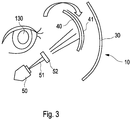
- the user equipment 10 has a partially reflective lens 40 for reflecting the screen 50, i.e. emitted light 51 having been emitted by the screen 50 and having passed imaging optics 52 of the user equipment 10, to the eye 130 of the user.
- the partially reflective lens 40 may have a reflective coating 41 and/or a protective coating.
- the reflective coating 41 and/or the protective coating are provided on a surface of the partially reflective lens 40 facing the field of view 31.
- the screen 50 is swivel-mounted to the frame 20 and swiveling between an active screen position with a virtual image of the reflected screen 50 overlaying the field of view 31 when the glasses 30 are arranged in front of the eyes 130 and an inactive screen position with the virtual image of the reflected screen 50 being outside the field of view 31.
- the human machine interface unit comprises an electric motor (not shown) for swivelling the screen 50 with respect to the frame 20, the electric motor linking the screen 50 and the frame 20.
- the electric motor is operatively connected to the control unit 100.
- the partially reflective lens 40 is separate from the glasses 30, swivel-mounted to the frame 20 and swivelling between an active lens position and an inactive lens position corresponding to the active screen position and the inactive screen position, respectively.
- Figure 2 illustrates the active lens position.
- the human machine interface unit has an electromagnet (not shown) for swivelling the partially reflective lens 40 with respect to the frame 20.
- the electromagnet is operatively connected to the control unit 100.
- the control unit 100 is configured to swivel the screen 50 and the partially reflective lens 40 dependent on the detected viewing direction 131.
- Figure 3 schematically shows an enlarged view of a detail of the user equipment 10 shown in figure 2 .
- the user equipment 10 may be operated as follows.
- the user equipment 10 is worn by a user and the radio interface unit 90 of the user equipment 10 establishes a wireless connection to a cellular network.
- the screen 50 of the human machine interface unit of the user equipment 10 is swivelled to the active screen position due to an activating user action or due to a triggering event provided by an internet cloud via the wireless connection.
- the user action may be an eye 130 movement defining the viewing direction 131 of the user and being detected by the eye tracking unit 120 of the user equipment 10 or a muscle action, e.g. a movement of a body part, being detected by a sensoric clothing worn by the user and being wirelessly connected, e.g. via NFC or via a Bluetooth connection, to the user equipment 10.
- the triggering event may be an incoming telephone call or breaking news.
- the partially reflective lens 40 of the user equipment 10 is swivelled to the active lens position and to the inactive lens position, respectively, in a synchronity with the swivelling screen 50.
- the screen 50 displays digital data provided by the internet cloud.
- the displayed digital data for instance, is related to the incoming telephone call or the breaking news.
- the screen 50 is swivelled to the inactive screen position due to an inactivating user action or due to a time-out when the there is no user action or triggering event for a predetermined time interval.
- the at least one glass 30 may be configured to be the partially reflective lens 40.
Landscapes
- Engineering & Computer Science (AREA)
- Physics & Mathematics (AREA)
- General Engineering & Computer Science (AREA)
- General Physics & Mathematics (AREA)
- Theoretical Computer Science (AREA)
- Human Computer Interaction (AREA)
- Optics & Photonics (AREA)
Abstract
Description
- The invention relates to a user equipment, comprising a radio interface unit for a wireless connection, a human machine interface (HMI) unit for interacting with a user, the human machine interface unit having a screen for displaying digital data to be seen by the user, a control unit for operating the radio interface unit and the human machine interface unit, the control unit being operatively connected to the radio interface unit and the human machine interface, a frame supporting the radio interface unit, the human machine interface unit and the control unit.
- User equipments of the above-mentioned kind are known in many various embodiments and are widely used as mobile computing and communication devices, e.g. smartphones, tablets and the like. However, conventional user equipments suffer from attracting too much of a user's attention. Hence, they cannot be used or are not allowed to be used in certain situations, e.g. while driving a car. Apart from that, they usually require at least one hand, mostly both hands, of the user for being operated. As a consequence, the user's hand is prevented from doing other things while operating the user equipment.
- It is, therefore, an object of the invention to provide a user equipment which attracts less attention of a user and leaves hands of the user free during usage thereof. It is another object of the invention to suggest a method for operating a user equipment.
- One aspect of the invention is a user equipment, comprising a radio interface unit for a wireless connection, a human machine interface unit for interacting with a user, the human machine interface unit having a screen for displaying digital data to be seen by the user, a control unit for operating the radio interface unit and the human machine interface unit, the control unit being operatively connected to the radio interface unit and the human machine interface, a frame supporting the radio interface unit, the human machine interface unit and the control unit, and at least one glass defining a field of view of the user equipment, the frame supporting the at least one glass and being configured for arranging the at least one glass in front of an eye of the user. The user equipment is similar to data glasses or data goggles.
- According to the invention, the user equipment comprises at least one glass defining a field of view of the user equipment, the frame supporting the at least one glass and being configured for arranging the at least one glass in front of an eye of the user, a partially reflective lens for reflecting the screen to the eye of the user, wherein the screen is swivel-mounted to the frame and swiveling between an active screen position with a virtual image of the reflected screen overlaying the field of view when the glass is arranged in front of the eye and an inactive screen position with the virtual image of the reflected screen being outside the field of view. The user equipment, thus, may be optionally used either as conventional glasses or as data glasses. The user equipment is configured to be a head-mounted device, particularly a wearable smartphone, leaving hands of the user free during usage. The screen of the user equipment may correspond to a display of a conventional smartphone.
- In some embodiments the at least one glass is configured to be the partially reflective lens. In other words, the at least one glass provides a partial reflectivity for reflecting the screen. The double function of the at least one glass provides both a small part count of the user equipment and a low mechanical complexity of the user equipment. A low mechanical complexity may facilitate handling of the user equipment, increase a life time of the user equipment and decrease a risk of failure of the user equipment.
- In alternative embodiments, the partially reflective lens is separate from the at least one glass, swivel-mounted to the frame and swivelling between an active lens position and an inactive lens position corresponding to the active screen position and the inactive screen position, respectively. In the active lens position, the partially reflective lens is arranged between the eye of the user and the at least one glass. Accordingly, the viewing direction of the user passes the partially reflective lens.
- Preferably, the partially reflective lens has a reflective coating and/or a protective coating, the reflective coating and/or the protective coating being provided on a surface of the partially reflective lens facing the field of view. The reflective coating prevents the digital data to be seen from other persons facing the user wearing the user equipment. The reflective coating gives the partially reflective lens a mirrored appearance. The reflective coating ensures a privacy of the digital data displayed by the screen and, thus, supports data protection according to legal provisions. It is noted that the reflective coating is different from the partial reflectivity provided by the lens for reflecting light emitted by the screen into the eye of the user. The protective coating may protect the lens from a damage caused by mechanical impact, e.g. from scratches or cracks.
- In advantageous embodiments, the user equipment comprises a pair of glasses being supported by the frame and being arranged next to each other, the frame being a glasses frame having a bridge for abutting a nose of the user. The user equipment is configured as conventional glasses to be supported by the nose of the user.
- In another embodiment, the human machine interface has a microphone for detecting a voice utterance, the microphone being supported by the frame. The microphone enables the user equipment for being acustically operated by the user. Apart from that, the microphone may be configured for recording an environmental sound or noise, e.g. traffic noise, a vocal performance, a conversation, a speech and the like.
- Moreover, the human machine interface may have a loudspeaker or the like for generating sounds to be heard by the user. The loudspeaker may be arranged on an earpiece of the frame or configured as an earplug.
- Additionally or alternatively, the human machine interface may have an eye tracking unit for detecting a viewing direction of the user, the eye tracking unit being supported by the frame. The eye tracking unit is configured to signal the detected viewing direction of the user to the control unit.
- The control unit is preferably configured to swivel the screen dependent on the detected viewing direction. Thus, the screen is enabled to always follow the view of the user. The user sees the displayed digital data independently of a viewing direction of the eyes as long as the viewing direction passes the glass and does not leave the field of view.
- In these embodiments, the human machine interface unit may comprise an electric motor for swivelling the screen with respect to the frame, the electric motor linking the screen and the frame and/or an electromagnet for swivelling the partially reflective lens with respect to the frame. The electric motor allows the screen to be swivelled automatically. The electromagnet provides a magnetic field applying a magnetic force to the reflective lens which allows for a noncontact operation of the reflective lens.
- Advantageously, the control unit has an embedded subscriber identification module (eSIM) for a cellular network and/or the radio interface unit is configured for connecting to a cellular network and/or for connecting to a Bluetooth device and/or for a near field communication. The eSIM may be easily integrated within the control unit and, hence, a separate SIM card is not required. Therewith, handling of the user equipment is facilitated. It is noted that the control unit is not limited to an embedded eSIM and may have any embedded authentication means for any radio access network.
- The Bluetooth connectivity allows for easily connecting the user equipment with a NFC capable device or a Bluetooth device worn by the user, e.g. a smart watch or sensoric clothing. As a result, the NVC capable device or the Bluetooth device extents the human machine interface unit of the user equipment allowing for additional ways of operating the user equipment. For instance, the user equipment may be operable by the user simply moving a part of the body.
- The radio interface unit may further be configured for connecting to a WLAN router and/or for being connected to as a WLAN router. The connection to the WLAN router provides an alternative access to the internet cloud. The WLAN connection may be used where a radio access network is not accessible or in order to save download costs or upload costs caused by using a radio access network.
- In other embodiments, the user equipment comprises a camera for capturing an image of the field of view and/or a GPS unit for detecting a geographical position. The images captured by the camera are very similar to the views seen by the user. The GPS (Global Positioning System) unit allows for localizing every captured image, i.e. providing every captured image Instead, the camera comprises any sensor detecting electromagnetic waves and providing an image of the field of view defined by the user equipment or even a surrounding of the user wearing the user equipment, e.g. an infrared camera or a radar sensor.
- Another object of the invention is a method for operating a user equipment, comprising the following steps. A user equipment according to the invention is worn by a user and the radio interface unit of the user equipment establishes a wireless connection. The screen of the human machine interface unit of the user equipment is swivelled to the active screen position due to an activating user action or due to a triggering event provided by an internet cloud via the wireless connection. The screen displays digital data provided by the internet cloud. The screen is swivelled to the inactive screen position due to an inactivating user action or due to a time-out. For instance, an incoming telephone call or breaking news may be the triggering event. In short, the user equipment optionally is operated as a wearable smartphone. When the user equipment is not operated like this, it may be used as conventional glasses.
- In many embodiments, the partially reflective lens of the user equipment is swivelled to the active lens position and to the inactive lens position, respectively, in a synchronity with the swivelling screen. Due to the synchronized swivelling of the screen and the partially reflective lens the glass is prevented from unintentionally reflecting light emitted by the screen into the eye of the user.
- Preferably, the user equipment is operated by an eye movement defining a viewing direction of the user and being detected by the eye tracking unit of the user equipment and/or by a muscle action being detected by a sensoric clothing worn by the user and being wirelessly connected to the user equipment. Operating the user equipment is both silent and robust against an influence of a surrounding of the user, e.g. a noise and the like. Apart from that, hands of the user are left free from any operating activity during usage.
- It is an essential advantage of the user equipment according to the invention that it may be used like a conventional smartphone without requiring a hand of a user for being operated. Another advantage of the inventive user equipment is an ease of handling which does not exceed a handling of conventional glasses.
- Further advantages and configurations of the invention become apparent from the following description and the enclosed drawings.
- It shall be understood that the features described previously and to be described subsequently may be used not only in the indicated combinations but also in different combinations or on their own without leaving the scope of the present invention.
- The invention is described in detail by means of an exemplary embodiment and with reference to the drawings.
- Fig. 1
- schematically shows a perspective view of a user equipment according to an embodiment of the invention;
- Fig. 2
- schematically shows a partial lateral view of the user equipment shown in
fig. 1 ; - Fig. 3
- schematically shows an enlarged view of a detail of the user equipment shown in
fig. 2 . -
Figure 1 schematically shows a perspective view of a user equipment according 10 to an embodiment of the invention. - The
user equipment 10 comprises aradio interface unit 90 for a wireless connection. Theradio interface unit 90 is preferably configured for at least one of connecting to a cellular network and connecting to a Bluetooth device and a near field communication. Theradio interface unit 90 may be further configured for connecting to a WLAN router and/or for being connected to as a WLAN router. - The
user equipment 10 comprises also a human machine interface (HMI) unit for interacting with a user. The human machine interface unit has ascreen 50 for displaying digital data, e.g. text content or multimedia content, to be seen by the user. The human machine interface unit further has amicrophone 70 for detecting a voice utterance of the user, aloudspeaker 80 for generating a sound for an ear of the user and an eye tracking unit 120 (hidden by the frame) for detecting aviewing direction 131 of the user. - The
user equipment 10 preferably comprises acamera 60 for capturing an image of a field ofview 31 and/or aGPS unit 110 for detecting a geographical position of the user equipment. - Furthermore, the
user equipment 10 comprises acontrol unit 100 for operating theradio interface unit 90 and the human machine interface unit. Thecontrol unit 100 has an embedded subscriber identification module (eSIM) 101 for a cellular network and is operatively connected to thecamera 60,radio interface unit 90, theGPS unit 110 and the human machine interface. - The
user equipment 10 comprises a pair ofglasses 30 being arranged next to each other and defining the field ofview 31 of theuser equipment 10 and aframe 20. Theframe 20 is a glasses frame being configured for arranging eachglass 30 in front of aneye 130 of the user. Generally, the user equipment has at least oneglass 30. - The
frame 20 has abridge 21 for abutting a nose of the user and twoearpiedes 22 for abutting either ear of the user and supports theglasses 30, thecamera 60, theradio interface unit 90, thecontrol unit 100, theGPS unit 110 and the human machine interface unit with thescreen 50, themicrophone 70, theloudspeaker 80. Thecamera 60, theradio interface unit 90, thecontrol unit 100, theGPS unit 110 and themicrophone 70, theloudspeaker 80 and theeye tracking unit 120 of the human machine interface unit are integrated within theframe 20. -
Figure 2 schematically shows a partial lateral view of theuser equipment 10 shown infigure 1 . - The
user equipment 10 has a partiallyreflective lens 40 for reflecting thescreen 50, i.e. emitted light 51 having been emitted by thescreen 50 and having passedimaging optics 52 of theuser equipment 10, to theeye 130 of the user. The partiallyreflective lens 40 may have areflective coating 41 and/or a protective coating. Thereflective coating 41 and/or the protective coating are provided on a surface of the partiallyreflective lens 40 facing the field ofview 31. - The
screen 50 is swivel-mounted to theframe 20 and swiveling between an active screen position with a virtual image of the reflectedscreen 50 overlaying the field ofview 31 when theglasses 30 are arranged in front of theeyes 130 and an inactive screen position with the virtual image of the reflectedscreen 50 being outside the field ofview 31. The human machine interface unit comprises an electric motor (not shown) for swivelling thescreen 50 with respect to theframe 20, the electric motor linking thescreen 50 and theframe 20. The electric motor is operatively connected to thecontrol unit 100. - The partially
reflective lens 40 is separate from theglasses 30, swivel-mounted to theframe 20 and swivelling between an active lens position and an inactive lens position corresponding to the active screen position and the inactive screen position, respectively.Figure 2 illustrates the active lens position. The human machine interface unit has an electromagnet (not shown) for swivelling the partiallyreflective lens 40 with respect to theframe 20. The electromagnet is operatively connected to thecontrol unit 100. - The
control unit 100 is configured to swivel thescreen 50 and the partiallyreflective lens 40 dependent on the detectedviewing direction 131. -
Figure 3 schematically shows an enlarged view of a detail of theuser equipment 10 shown infigure 2 . - The
user equipment 10 may be operated as follows. Theuser equipment 10 is worn by a user and theradio interface unit 90 of theuser equipment 10 establishes a wireless connection to a cellular network. - The
screen 50 of the human machine interface unit of theuser equipment 10 is swivelled to the active screen position due to an activating user action or due to a triggering event provided by an internet cloud via the wireless connection. - The user action may be an
eye 130 movement defining theviewing direction 131 of the user and being detected by theeye tracking unit 120 of theuser equipment 10 or a muscle action, e.g. a movement of a body part, being detected by a sensoric clothing worn by the user and being wirelessly connected, e.g. via NFC or via a Bluetooth connection, to theuser equipment 10. The triggering event may be an incoming telephone call or breaking news. - The partially
reflective lens 40 of theuser equipment 10 is swivelled to the active lens position and to the inactive lens position, respectively, in a synchronity with theswivelling screen 50. - The
screen 50 displays digital data provided by the internet cloud. The displayed digital data, for instance, is related to the incoming telephone call or the breaking news. - The
screen 50 is swivelled to the inactive screen position due to an inactivating user action or due to a time-out when the there is no user action or triggering event for a predetermined time interval. - In an alternative embodiment the at least one
glass 30 may be configured to be the partiallyreflective lens 40. -
- 10
- user equipment
- 20
- frame
- 21
- bridge
- 22
- earpiece
- 30
- glass
- 31
- field of view
- 40
- partially reflective lens
- 41
- reflective coating
- 50
- screen
- 51
- emitted light
- 52
- imaging optics
- 60
- camera
- 70
- microphone
- 80
- loudspeaker
- 90
- radio interface
- 100
- control unit
- 101
- eSIM
- 110
- GPS unit
- 120
- eye tracking unit
- 130
- eye
- 131
- viewing direction
Claims (15)
- A user equipment (10), comprising :- a radio interface unit (90) for a wireless connection ;- a human machine interface unit for interacting with a user, the human machine interface unit having a screen (50) for displaying digital data to be seen by the user;- a control unit (100) for operating the radio interface unit (90) and the human machine interface unit, the control unit (100) being operatively connected to the radio interface unit (90) and the human machine interface ;- a frame (20) supporting the radio interface unit (90), the human machine interface unit and the control unit (100) ;- at least one glass (30) defining a field of view (31) of the user equipment (10), the frame (20) supporting the at least one glass (30) and being configured for arranging the at least one glass (30) in front of an eye (130) of the user; and- a partially reflective lens (40) for reflecting the screen (50) to the eye (130) of the user, wherein the screen (50) is swivel-mounted to the frame (20) and swiveling between an active screen position with a virtual image of the reflected screen (50) overlaying the field of view (31) when the glass (30) is arranged in front of the eye (130) and an inactive screen position with the virtual image of the reflected screen (50) being outside the field of view (31).
- The user equipment according to claim 1, wherein the at least one glass (30) is configured to be the partially reflective lens (40).
- The user equipment according to claim 1, wherein the partially reflective lens (40) is separate from the at least one glass (30), swivel-mounted to the frame (20) and swivelling between an active lens position and an inactive lens position corresponding to the active screen position and the inactive screen position, respectively.
- The user equipment according to claim 3, wherein the partially reflective lens (40) has a reflective coating (41) and/or a protective coating, the reflective coating (41) and/or the protective coating being provided on a surface of the partially reflective lens (40) facing the field of view (31).
- The user equipment according to one of claims 1 to 4, comprising a pair of glasses (30) being supported by the frame (20) and being arranged next to each other, the frame (20) being a glasses frame having a bridge (21) for abutting a nose of the user.
- The user equipment according to one of claims 1 to 5, wherein the human machine interface has a microphone (70) for detecting a voice utterance, the microphone (70) being supported by the frame (20).
- The user equipment according to one of claims 1 to 6, wherein the human machine interface has an eye tracking unit (120) for detecting a viewing direction (131) of the user, the eye tracking unit (120) being supported by the frame (20).
- The user equipment according to claim 7, wherein the control unit (100) is configured to swivel the screen (50) dependent on the detected viewing direction (131).
- The user equipment according to one of claims 1 to 8, wherein the human machine interface unit comprises an electric motor for swivelling the screen (50) with respect to the frame (20), the electric motor linking the screen (50) and the frame (20) and/or an electromagnet for swivelling the partially reflective lens (40) with respect to the frame (20).
- The user equipment according to one of claims 1 to 9, wherein the control unit (100) has an embedded subscriber identification module (101) for a cellular network and/or the radio interface unit (90) is configured for connecting to cellular network and/or for connecting to a Bluetooth device and/or for a near field communication.
- The user equipment according to one of claims 1 to 10, wherein the radio interface unit (90) is configured for connecting to a WLAN router and/or for being connected to as a WLAN router.
- The user equipment according to one of claims 1 to 11, comprising a camera (60) for capturing an image of the field of view (31) and/or a GPS unit (110) for detecting a geographical position.
- A method for operating a user equipment (10), comprising the steps :- a user equipment (10) according to one of the prececing claims is worn by a user and the radio interface unit (90) of the user equipment (10) establishes a wireless connection ;- the screen (50) of the human machine interface unit of unit the user equipment (10) is swivelled to the active screen position due to an activating user action or due to a triggering event provided by an internet cloud via the wireless connection ;- the screen (50) displays digital data provided by the internet cloud ; and- the screen (50) is swivelled to the inactive screen position due to an inactivating user action or due to a time-out;
- The method according to claim 13, wherein the partially reflective lens (40) of the user equipment (10) is swivelled to the active lens position and to the inactive lens position, respectively, in a synchronity with the swivelling screen (50).
- The method according to one of claims 13 or 14, wherein the user equipment (10) is operated by an eye (130) movement defining a viewing direction (131) of the user and being detected by the eye tracking unit (120) of the user equipment (10) and/or by a muscle action being detected by a sensoric clothing worn by the user and being wirelessly connected to the user equipment (10).
Priority Applications (1)
| Application Number | Priority Date | Filing Date | Title |
|---|---|---|---|
| EP20162619.9A EP3879385A1 (en) | 2020-03-12 | 2020-03-12 | Head-mountable user equipment |
Applications Claiming Priority (1)
| Application Number | Priority Date | Filing Date | Title |
|---|---|---|---|
| EP20162619.9A EP3879385A1 (en) | 2020-03-12 | 2020-03-12 | Head-mountable user equipment |
Publications (1)
| Publication Number | Publication Date |
|---|---|
| EP3879385A1 true EP3879385A1 (en) | 2021-09-15 |
Family
ID=69804789
Family Applications (1)
| Application Number | Title | Priority Date | Filing Date |
|---|---|---|---|
| EP20162619.9A Withdrawn EP3879385A1 (en) | 2020-03-12 | 2020-03-12 | Head-mountable user equipment |
Country Status (1)
| Country | Link |
|---|---|
| EP (1) | EP3879385A1 (en) |
Citations (6)
| Publication number | Priority date | Publication date | Assignee | Title |
|---|---|---|---|---|
| US20120235887A1 (en) * | 2010-02-28 | 2012-09-20 | Osterhout Group, Inc. | See-through near-eye display glasses including a partially reflective, partially transmitting optical element and an optically flat film |
| US20130114146A1 (en) * | 2011-11-04 | 2013-05-09 | Honeywell International Inc. | Steerable near-to-eye display and steerable near-to-eye display system |
| US20150177519A1 (en) * | 2013-12-19 | 2015-06-25 | Google Inc. | See-through eyepiece for head wearable display |
| WO2017120353A1 (en) * | 2016-01-06 | 2017-07-13 | Vuzix Corporation | Head-mounted display with pivoting display |
| WO2019024992A1 (en) * | 2017-08-02 | 2019-02-07 | Huawei Technologies Co., Ltd. | Eyeglass frame |
| EP3511767A1 (en) * | 2018-01-16 | 2019-07-17 | BAE SYSTEMS plc | Wearable devices |
-
2020
- 2020-03-12 EP EP20162619.9A patent/EP3879385A1/en not_active Withdrawn
Patent Citations (6)
| Publication number | Priority date | Publication date | Assignee | Title |
|---|---|---|---|---|
| US20120235887A1 (en) * | 2010-02-28 | 2012-09-20 | Osterhout Group, Inc. | See-through near-eye display glasses including a partially reflective, partially transmitting optical element and an optically flat film |
| US20130114146A1 (en) * | 2011-11-04 | 2013-05-09 | Honeywell International Inc. | Steerable near-to-eye display and steerable near-to-eye display system |
| US20150177519A1 (en) * | 2013-12-19 | 2015-06-25 | Google Inc. | See-through eyepiece for head wearable display |
| WO2017120353A1 (en) * | 2016-01-06 | 2017-07-13 | Vuzix Corporation | Head-mounted display with pivoting display |
| WO2019024992A1 (en) * | 2017-08-02 | 2019-02-07 | Huawei Technologies Co., Ltd. | Eyeglass frame |
| EP3511767A1 (en) * | 2018-01-16 | 2019-07-17 | BAE SYSTEMS plc | Wearable devices |
Similar Documents
| Publication | Publication Date | Title |
|---|---|---|
| US12401741B2 (en) | Server, client terminal, control method, and storage medium | |
| US12032155B2 (en) | Method and head-mounted unit for assisting a hearing-impaired user | |
| CN104995545B (en) | Wearable individual digital glasses device | |
| US9351141B2 (en) | Headset computer with handsfree emergency response | |
| JP6743691B2 (en) | Display control device, display control method, and computer program | |
| EP2955610B1 (en) | Method and head mounted device for providing user input to an electronic device | |
| US7313246B2 (en) | Information system using eyewear for communication | |
| US10459236B2 (en) | Head-mounted display device with earbud holder | |
| US20060148540A1 (en) | Portable terminal device | |
| US20140236594A1 (en) | Assistive device for converting an audio signal into a visual representation | |
| KR20150084608A (en) | Terminal and operating method thereof | |
| JP2001522063A (en) | Eyeglass interface system | |
| US20060203998A1 (en) | Eyeglass-attached video display based on wireless transmission from a cell phone | |
| US11037519B2 (en) | Display device having display based on detection value, program, and method of controlling device | |
| JP5675155B2 (en) | Head-mounted information notification device | |
| CN116860102A (en) | Wearing detection method and related device | |
| KR20150120102A (en) | Method for controlling information display at mobile device interworking with wearable device | |
| CN106031135B (en) | Wearable device and communication control method | |
| KR101614315B1 (en) | Wearable device and method for controlling the same | |
| US20070081125A1 (en) | Digital eyewear for telecommunications | |
| JP2015220684A (en) | Portable terminal device and lip reading processing program | |
| KR101871660B1 (en) | Wearable based personal auto recording device operation method | |
| JP2017183857A (en) | Head-mounted display device, head-mounted display device control method, computer program | |
| KR20160016216A (en) | System and method for real-time forward-looking by wearable glass device | |
| KR101594429B1 (en) | Method and apparutus for controlling emergency call |
Legal Events
| Date | Code | Title | Description |
|---|---|---|---|
| PUAI | Public reference made under article 153(3) epc to a published international application that has entered the european phase |
Free format text: ORIGINAL CODE: 0009012 |
|
| STAA | Information on the status of an ep patent application or granted ep patent |
Free format text: STATUS: REQUEST FOR EXAMINATION WAS MADE |
|
| 17P | Request for examination filed |
Effective date: 20210126 |
|
| AK | Designated contracting states |
Kind code of ref document: A1 Designated state(s): AL AT BE BG CH CY CZ DE DK EE ES FI FR GB GR HR HU IE IS IT LI LT LU LV MC MK MT NL NO PL PT RO RS SE SI SK SM TR |
|
| STAA | Information on the status of an ep patent application or granted ep patent |
Free format text: STATUS: EXAMINATION IS IN PROGRESS |
|
| 17Q | First examination report despatched |
Effective date: 20220105 |
|
| STAA | Information on the status of an ep patent application or granted ep patent |
Free format text: STATUS: THE APPLICATION IS DEEMED TO BE WITHDRAWN |
|
| 18D | Application deemed to be withdrawn |
Effective date: 20220716 |