EP3879254B1 - Tyre inspection method - Google Patents
Tyre inspection method Download PDFInfo
- Publication number
- EP3879254B1 EP3879254B1 EP20382185.5A EP20382185A EP3879254B1 EP 3879254 B1 EP3879254 B1 EP 3879254B1 EP 20382185 A EP20382185 A EP 20382185A EP 3879254 B1 EP3879254 B1 EP 3879254B1
- Authority
- EP
- European Patent Office
- Prior art keywords
- tyre
- adjusting
- support
- devices
- frame
- Prior art date
- Legal status (The legal status is an assumption and is not a legal conclusion. Google has not performed a legal analysis and makes no representation as to the accuracy of the status listed.)
- Active
Links
Images


Classifications
-
- B—PERFORMING OPERATIONS; TRANSPORTING
- B60—VEHICLES IN GENERAL
- B60C—VEHICLE TYRES; TYRE INFLATION; TYRE CHANGING; CONNECTING VALVES TO INFLATABLE ELASTIC BODIES IN GENERAL; DEVICES OR ARRANGEMENTS RELATED TO TYRES
- B60C25/00—Apparatus or tools adapted for mounting, removing or inspecting tyres
- B60C25/002—Inspecting tyres
-
- G—PHYSICS
- G01—MEASURING; TESTING
- G01M—TESTING STATIC OR DYNAMIC BALANCE OF MACHINES OR STRUCTURES; TESTING OF STRUCTURES OR APPARATUS, NOT OTHERWISE PROVIDED FOR
- G01M17/00—Testing of vehicles
- G01M17/007—Wheeled or endless-tracked vehicles
- G01M17/02—Tyres
- G01M17/021—Tyre supporting devices, e.g. chucks
-
- G—PHYSICS
- G01—MEASURING; TESTING
- G01M—TESTING STATIC OR DYNAMIC BALANCE OF MACHINES OR STRUCTURES; TESTING OF STRUCTURES OR APPARATUS, NOT OTHERWISE PROVIDED FOR
- G01M17/00—Testing of vehicles
- G01M17/007—Wheeled or endless-tracked vehicles
- G01M17/02—Tyres
- G01M17/022—Tyres the tyre co-operating with rotatable rolls
-
- G—PHYSICS
- G01—MEASURING; TESTING
- G01M—TESTING STATIC OR DYNAMIC BALANCE OF MACHINES OR STRUCTURES; TESTING OF STRUCTURES OR APPARATUS, NOT OTHERWISE PROVIDED FOR
- G01M17/00—Testing of vehicles
- G01M17/007—Wheeled or endless-tracked vehicles
- G01M17/02—Tyres
- G01M17/027—Tyres using light, e.g. infrared, ultraviolet or holographic techniques
Definitions
- the invention tyre support device, relates to a device designed for supporting a tyre and thus enabling the inspection thereof, manually by a user or automated by means of vision systems or devices, enabling the repair thereof, or even enabling trimming or removal of burrs (also manually or automated).
- the device enables the tyre to be arranged in a specific position, after adjusting to the size of the tyre while the same rotates without longitudinal movement, avoiding deformation and reducing vibration.
- the field of application of the present invention falls within the automotive industry sector, specifically focussing on the field of the industry dedicated to the manufacture of apparatuses and devices to carry out tyre manufacturing and/or repairing tasks, and more particularly to tyre inspection tasks, preferably using automated vision systems.
- the tyre In addition to the constitution of the tyres, it must be taken into account that it is necessary to inspect all the surfaces completely, hence the tyre must be handled several times to complete the thorough inspection of the tyre.
- the constitution of the tyre can cause deformations that limit the precision that such automated inspection systems can offer, thereby losing the effectiveness sought by the same and causing human inspection of the tyres to be still necessary.
- tyre sector there are other devices for handling tyres for other purposes, such as tyre repair or removal of burrs after manufacture.
- Document US2011188052A relates to a method of determining geometrical dimensions of a tyre, especially of an inner surface of the tyre and/or a tyre bead, by contact-less sensing, wherein the tyre is received in a receiving means. At least one light beam is emitted onto a peripheral area of the tyre surface, especially on an inner surface of the tyre and/or on a tyre bead, and are evaluated for determining the shape and/or position of the respective impingement area on the tyre.
- the invention relates to an apparatus for determining the geometrical dimensions of a tyre comprising at least one sensing device and a computer-aided evaluation arrangement, wherein the evaluation arrangement is suitable for determining the position of the location sensed by the light beam on the tyre surface from the directions of the emitted light beam and the reflected light beam.
- Prior art document DE202006011739U1 refers to a device that has tires wound on a wheel rim.
- a wheel support has roller cylinders, on which a wheel is displaced in a fixed rolling position in rotation about a rolling axis.
- the wheel support has a wheel bearing for providing a lateral support of the wheel in a rolling position, where the wheel bearing is provided with freely rotatable supporting rollers for the lateral arrangement of the wheel.
- the object of the present invention is a tyre inspection method according to claim 1.
- the support device preferably comprises three adjusting devices on the inclined frame and is supported on a preferably horizontal surface, such that two of the adjusting devices are located on the lower portion of said frame and the third adjusting device is located on the upper surface, all of them concentric to the tyre axis.
- the support device comprises rest or support means for the tyre, which further comprise rotation means that cause the tangential rotation of the tyre on the axis thereof by providing traction on the tyre tread, that is, motorised support and rotation means.
- the device has the three adjusting devices located at 120° from each other, two in the lower portion and one in the upper portion, the three adjusting devices being concentric with respect to the tyre axis.
- the support device comprises only two adjusting devices located in the lower portion of the frame with the support and rotation means, that is, without the upper adjusting device, so that the tyre rests directly on the frame, or on a support element, in said upper area, and because the rotation and support would be done on the lower adjusting devices.
- an upper adjusting device could be provided without resting or support means since said upper adjusting device does not provide traction to the tyre and the main function thereof is to avoid vibrations in the event that they appear.
- an upper adjusting device could be provided with the adjusting means and with the support means but without motorised rotation means.
- the frame of the support device where the adjusting devices rest has an inclined structure with a window, so that the frame has the shape of an inclined frame on a support structure of all the elements of the device.
- the inclination of the frame structure is between 15° and 30°, preferably 20°, with respect to an approximately vertical plane, said approximately vertical plane being preferably perpendicular to the frame support structure and therefore also perpendicular to the surface where said support structure rests, this surface being therefore the one where the whole device rests. That is, the support structure has an inclination of between 60° and 75° with respect to a horizontal surface.
- the axis of the tyre will form 90° with said support structure on which it rests.
- the aforementioned inclination of the support structure enables the swinging of the tyre when it rotates to be prevented, swinging that does occur when the tyre is supported on the tread thereof, at the same time resting on a horizontal surface.
- Each of said lower adjusting devices comprises as support means an shaft or roller where the tyre rests, so that the rotation of said shaft constitutes at the same time the rotation means to rotate the tyre on the axis thereof and at the same time support the tyre that prevents deformation when it rotates, the speed of the tyre preferably being between 10 and 15 rpm.
- the upper adjusting device has, as support means, preferably two shafts or rollers, not motorised and slightly separated from each other, with the aim of preventing the tyre from coming out of the device when applying the corresponding turning speed from the shafts or rollers of the lower adjusting devices.
- the first adjusting means for adjusting to the width, the second adjusting means for adjusting to the diameter, as well as the rotation means of each adjusting device are preferably displaced and/or moved by servo motors.
- the first adjusting means to the width of the tyre comprise a first U-shaped support, with a fixed first end and a second end, parallel to the first end, movable by a servo motor, such that the second end can be adapted to the width of the tyre once the tyre tread is inserted into said U-shaped support.
- the second adjusting means for adjusting to the diameter of the tyre comprise a second support movable over a surface, preferably with one or two rails arranged in turn on the frame of the device or on an extension thereof, for example, on plates or flat sheets on which displacement rails are arranged.
- the first support is arranged on said second support with the first adjusting means for adjusting to the width of the tyre. In this way, the second adjusting means will move the second support along the rail or rails located in the frame and, in turn, will move the first adjusting means that are arranged over the second adjusting means.
- the adjusting means for the diameter are arranged so as to enable the movement of the adjusting means to the width of the tyre along shafts at 120°, maintaining equidistance between the three adjusting devices.
- the intersection point of said shafts is the point where the centre and axis of the tyre must be placed on the device. That is, the rails are arranged so that the first and second adjusting means, and therefore the adjusting devices, move concentrically with respect to the centre of the tyre that is arranged in the support device.
- This concentric movement in the upper adjusting device is preferably vertical.
- the rails on which they move are preferably arranged so that the lower adjusting devices move from one side to the other of the frame, parallel to a horizontal surface, varying the distance between them, while in the case of the upper adjusting device said rails are perpendicular to the previous ones and move from top to bottom.
- the support device object of the invention comprises support means and rotation means as described above.
- Said support and rotation means can correspond to the same means, such that the support means and the rotation means are the same drive shaft or roller, which happens in the lower adjusting devices, where the shaft or roller is arranged preferably on the U-shaped support, between the first end, which is fixed, and the second end, which is movable.
- the upper adjusting device may or may not have these support means and rotation means, it may have the support means but not the rotation means, or it may have both.
- the upper adjusting device has two shafts or rollers as support means.
- the device object of the invention can also incorporate, to facilitate access to the interior of the tyre, specifically to the interior of the tyre tread, as well as to the interior of the sides, a mechanism for opening the tyre that is integrated in the lower adjusting devices.
- Said mechanism preferably pneumatic, has claws that are inserted in the interior of the tyre from the side thereof and that when opened cause the separation of the sides of the tyre, thus facilitating access to the interior thereof, both to the interior of the tyre tread and to the interior of the sides.
- Said claws have rollers or cylinders at their ends that enable the tyre to rotate.
- the mechanical elements to achieve the movements and adjustments of the previous devices and means may vary, as well as the components that make them up.
- the tyre support device according to the claimed invention works as follows:
- the device includes a tyre opening mechanism, it will act before activating the rotation of the shafts or rollers of the lower adjusting devices.
- the device object of the invention is preferably used for automated tyre inspection, so it will be necessary to have vision systems or display elements, usually cameras and profilometers, to be able to inspect all parts of the tyre, namely:
- the vision systems will be installed, as far as possible, in the tyre support device itself and when this is not possible because either the handling of the tyre prevents it or the required angle of inclination of the vision system requires it, any necessary means will be used, mainly robotic arms that incorporate said vision systems at their ends.
- the systems for viewing the outer side of the tyre tread, as well as the outer side of the sides are arranged on the upper fixing device, in frames arranged for this purpose.
- Such frames could be arranged elsewhere as long as they do not interfere with the operation of the device components.
- vision systems are inserted through the hole of the tyre to access the interior of the tyre tread and the interior of the sides. Access to the interior can be done both from one side of the frame and from the opposite side through the hollow or window made in it.
- the support device comprises an inclined frame (10), which can be arranged on a support structure (not shown), preferably supported on a horizontal surface, with
- the frame (10) has an inclined structure with a central window or hollow (11), preferably in the shape of a housing, the inclination of the structure preferably being close to 20°, between 15° and 30°, with respect to a perpendicular to a supporting horizontal surface.
- the three adjusting devices (50, 60, 70) are arranged, the two lower adjusting devices (50, 60) having first adjusting means for adjusting to the width (3), second adjusting means for adjusting to the diameter (4) of the tyre and support means (5) of the tyre that coincide with the motorised rotation means of the tyre on the axis thereof, specifically rollers or cylinders (5).
- the upper adjusting device (70) preferably further has adjusting means (3, 4) as well as the above support means (5) present in the two lower adjusting devices (50, 60), although preferably it does not have any motorised rotation means, such that the support means (5) of the upper adjusting device (70) rotate due to the traction transmitted by the rotating tyre itself due to the action of the motorised rotation means (5) of the lower adjusting devices (50, 60).
- the support device object of the invention may not have (not shown) any upper adjusting device (70), such that the tyre would rest directly on the upper portion of the frame (10) or on a roller or rollers arranged for this purpose on the frame (10).
- Each of the lower adjusting devices (50, 60) comprises, as support means (5) and rotation means, an shaft, roller or cylinder (5) that performs said support and rotation of the tyre functions, said shaft, roller or cylinder (5) being motorised to be able to transmit that rotation to the tyre.
- Said shaft, roller or cylinder (5) is perpendicular to the frame (10) and constitutes the means for supporting and rotating the tyre on the very axis thereof since the tyre rests on said support and rotation shafts or rollers (5) of the lower adjusting devices (50, 60).
- the upper adjusting device (70) if the same does not exhibit rotation means, it is possible that it exhibits at least one shaft, roller or cylinder, as support means (5), which will also rotate dragged by the tyre.
- the shafts, rollers or cylinders of the support means (5) of the adjusting devices (50, 60, 70) are parallel to each other.
- said three adjusting devices (50, 60, 70) are incorporated into said frame (10) arranged in such a way that the two lower adjusting devices (50, 60) are located in the lower portion of the frame, (10) with their support and rotation shafts (5) separated and horizontally movable, and the upper adjusting device (70) is arranged on the upper portion of the frame (10) equidistant, at all times, to both lower adjusting devices (50, 60).
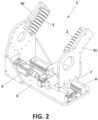
- Figure 2 shows the first adjusting means for adjusting to the width (3) which includes each adjusting device (50, 60, 70) and which are preferably determined by a U-shaped structure formed by two arms, one fixed (30) and one movable (31) (although they could be both movable), said structure moving on a runner (7) associated with a servomotor (6) and inserted into a rail (8) of a base plate (9), such that the movable arm (31) moves closer and further away from the fixed arm (30) to adjust to the width of the tyre.
- each arm (30, 31) the incorporation of a series of bearings (2) is envisaged, which are attached to the lateral surface of the tyre, rolling with it when turning it so as not to cause friction.
- the second adjusting means for adjusting to the diameter (4), shown in Figure 3 , of the adjusting devices (50, 60, 70) comprise a support plate (40) which, integrally attached to the frame (10) of the support device, is provided with rails (8) on which runners (7) run, associated with a servomotor (6), and on which a movable plate (41) is fixed on which, in turn, the U-shaped arms structure (30, 31) of the first adjusting means (3) is coupled with the corresponding support and rotation shaft (5) of the support means (5), to move said movable plate (41) from one end to the other of said support plate (40) and adjust the position thereof to the diameter of the tyre.
- Figure 3 shows how said second adjusting means for adjusting to the diameter (4), for the upper adjusting device (70), exhibit a vertical displacement movement of the movable plate (41), the support and rotation shaft (5), which rotates freely, being fastened directly to said plate (41), there being in said plate (41) spacers (42) on which the U-shaped arms structure (30, 31) of the first adjusting means (3) rests.
- the movable plate (41) exhibits a horizontal displacement movement, the support and rotation shafts (5) being drive rollers or cylinders.
- the rotation system of said rollers 5 can be made up of a servo motor (123) associated with a belt (122) associated with a planetary gear reduction system (12) formed by a rotating plate (120) and a pinion (121), in order to transmit the movement from the servomotor (123) to the roller (5).
- Other systems could also be used.
- FIGS 5 to 8 show a second exemplary embodiment of the invention.
- This second example shows a tyre support device (N) comprising an inclined frame (10) with a window or hollow (11) and arranged on a support structure (12).
- Said support device comprises:
- the adjusting devices (50, 60, 70) are arranged, as mentioned, on adjusting means for adjusting to the diameter (4) that serve to adjust the devices to the diameter of the tyre and stabilise the tyre, such that they move in parallel to axes at 120° that intersect at a point located on the axis (n) of the tyre arranged on the support device (10) object of the invention.
- this second example has an opening mechanism (80) of the tyre integrated in each of the lower adjusting devices (50, 60).
- This mechanism (80) which could also be integrated in the first exemplary embodiment, aims to facilitate access to the interior of the tyre, specifically to the interior of the tyre tread, as well as to the interior of the sides.
- Said mechanism (80) preferably actuated by pneumatic means, has claws (81) that are inserted inside the tyre (N) through the side thereof and when opened cause the separation of the sides of the tyre (N), thus facilitating access to the interior of the same, both to the interior of the tyre tread and the interior of the sides.
- Said claws (81) have at the ends thereof rollers or cylinders (82) that enable the tyre to rotate when the support and rotation means (5) arranged in the lower adjusting devices (50, 60) cause the rotation of the whole tyre.
- the adjusting means for adjusting to the diameter (4) of the three adjusting devices move, as mentioned, radially with respect to the centre of the tyre, each device maintaining equidistance with respect to the others as they approach or move away from the centre of the tyre depending on the dimensions of the tyre.
- the adjusting means to the width (3) also move on said adjusting means to the diameter.
- Said adjusting means to the width (3) have a configuration similar to that described for the first exemplary embodiment, wherein a first movable arm moves with respect to a second fixed arm, both arms being parallel and having bearings to facilitate the rotation of the tyre.
- the tyre rests on two arranged shafts, rollers or cylinders that form the support means (5), said support means being motorised and activated by servomotors (123) in the case of the lower adjusting devices (50, 60).
- the support means (5) are not motorised, but have a double support system formed by two rollers that are distanced from each other, acting as a stop and preventing the tyre from coming out of the support device as a result of rotation.
- This second example further shows how the upper adjusting device (70) integrates vision systems (90) formed by a camera or profilometer and a laser.
- vision systems 90
- FIG 8 although they are also seen in figures 5 and 6 , there are several vision devices or systems (90), two located in the upper portion to capture and record the tyre tread and two others located on each side of the tyre, capturing the sides thereof.
- the side of the tyre located on the side of the support device (10) is inspected by a vision system (90) that accesses said side through the window or hollow (11) of the frame (10).
- the light beams emitted by the necessary laser devices are observed so that the cameras or profilometers capture the surface with sufficient resolution.
Landscapes
- Physics & Mathematics (AREA)
- General Physics & Mathematics (AREA)
- Engineering & Computer Science (AREA)
- Mechanical Engineering (AREA)
- Tyre Moulding (AREA)
- Automobile Manufacture Line, Endless Track Vehicle, Trailer (AREA)
- Testing Of Balance (AREA)
- Investigating Materials By The Use Of Optical Means Adapted For Particular Applications (AREA)
- Vehicle Body Suspensions (AREA)
- Heating, Cooling, Or Curing Plastics Or The Like In General (AREA)
Description
- The invention, tyre support device, relates to a device designed for supporting a tyre and thus enabling the inspection thereof, manually by a user or automated by means of vision systems or devices, enabling the repair thereof, or even enabling trimming or removal of burrs (also manually or automated). The device enables the tyre to be arranged in a specific position, after adjusting to the size of the tyre while the same rotates without longitudinal movement, avoiding deformation and reducing vibration.
- The field of application of the present invention falls within the automotive industry sector, specifically focussing on the field of the industry dedicated to the manufacture of apparatuses and devices to carry out tyre manufacturing and/or repairing tasks, and more particularly to tyre inspection tasks, preferably using automated vision systems.
- Today, as in many other industrial areas, there are tasks that have been automated in such a way that machines and robots perform them that are more and more specific, and with increasingly reduced or limited human participation. An example of these are the tasks of visual inspection of tyres, the importance of which is essential for the correct operation and performance of the same, automated systems being able to provide a much higher level of precision than any human inspection, in addition to reducing errors in inspection and saving time in the same.
- In the state of the art, in addition to human tyre inspection, carried out at the end of each tyre manufacturing line, there are different automated inspection systems with vision systems. However, none of the known inspection systems enable the inspection to be carried out in a single station as they require handling and repositioning the tyre during the inspection in order to inspect all the surfaces thereof, namely: tyre tread, tyre interior and sides. The difficulties in handling and positioning the tyres to be inspected derive mainly from their geometry and composition, that is, a circular element made of a soft material, mainly rubber. In addition to the constitution of the tyres, it must be taken into account that it is necessary to inspect all the surfaces completely, hence the tyre must be handled several times to complete the thorough inspection of the tyre. The constitution of the tyre can cause deformations that limit the precision that such automated inspection systems can offer, thereby losing the effectiveness sought by the same and causing human inspection of the tyres to be still necessary.
- Likewise, in the tyre sector there are other devices for handling tyres for other purposes, such as tyre repair or removal of burrs after manufacture.
- Despite knowing the existence of different solutions for automated tyre inspection, usually with vision systems, none of them relates to a support device that makes it possible to adapt to tyres of different dimensions by means of a steady clamping without vibrations and that at the same time makes possible the inspection of the tyre without handling the tyre once it has been arranged on the support device.
- Document
US2011188052A relates to a method of determining geometrical dimensions of a tyre, especially of an inner surface of the tyre and/or a tyre bead, by contact-less sensing, wherein the tyre is received in a receiving means. At least one light beam is emitted onto a peripheral area of the tyre surface, especially on an inner surface of the tyre and/or on a tyre bead, and are evaluated for determining the shape and/or position of the respective impingement area on the tyre. Furthermore, the invention relates to an apparatus for determining the geometrical dimensions of a tyre comprising at least one sensing device and a computer-aided evaluation arrangement, wherein the evaluation arrangement is suitable for determining the position of the location sensed by the light beam on the tyre surface from the directions of the emitted light beam and the reflected light beam. - Prior art document
DE202006011739U1 refers to a device that has tires wound on a wheel rim. A wheel support has roller cylinders, on which a wheel is displaced in a fixed rolling position in rotation about a rolling axis. The wheel support has a wheel bearing for providing a lateral support of the wheel in a rolling position, where the wheel bearing is provided with freely rotatable supporting rollers for the lateral arrangement of the wheel. None of the known prior art documents disclose an inclined structure with a window and means to adapt to the diameter and width of the tyre. - The object of the present invention is a tyre inspection method according to claim 1.
- The support device preferably comprises three adjusting devices on the inclined frame and is supported on a preferably horizontal surface, such that two of the adjusting devices are located on the lower portion of said frame and the third adjusting device is located on the upper surface, all of them concentric to the tyre axis. Associated with said lower adjusting devices, the support device comprises rest or support means for the tyre, which further comprise rotation means that cause the tangential rotation of the tyre on the axis thereof by providing traction on the tyre tread, that is, motorised support and rotation means.
- Preferably the device has the three adjusting devices located at 120° from each other, two in the lower portion and one in the upper portion, the three adjusting devices being concentric with respect to the tyre axis.
- Likewise, it is also possible that the support device comprises only two adjusting devices located in the lower portion of the frame with the support and rotation means, that is, without the upper adjusting device, so that the tyre rests directly on the frame, or on a support element, in said upper area, and because the rotation and support would be done on the lower adjusting devices. Alternatively, an upper adjusting device could be provided without resting or support means since said upper adjusting device does not provide traction to the tyre and the main function thereof is to avoid vibrations in the event that they appear. Likewise, an upper adjusting device could be provided with the adjusting means and with the support means but without motorised rotation means.
- The frame of the support device where the adjusting devices rest has an inclined structure with a window, so that the frame has the shape of an inclined frame on a support structure of all the elements of the device. The inclination of the frame structure is between 15° and 30°, preferably 20°, with respect to an approximately vertical plane, said approximately vertical plane being preferably perpendicular to the frame support structure and therefore also perpendicular to the surface where said support structure rests, this surface being therefore the one where the whole device rests. That is, the support structure has an inclination of between 60° and 75° with respect to a horizontal surface. The axis of the tyre will form 90° with said support structure on which it rests. The aforementioned inclination of the support structure enables the swinging of the tyre when it rotates to be prevented, swinging that does occur when the tyre is supported on the tread thereof, at the same time resting on a horizontal surface.
- Each of said lower adjusting devices, and optionally the upper one, comprises as support means an shaft or roller where the tyre rests, so that the rotation of said shaft constitutes at the same time the rotation means to rotate the tyre on the axis thereof and at the same time support the tyre that prevents deformation when it rotates, the speed of the tyre preferably being between 10 and 15 rpm.
- The upper adjusting device has, as support means, preferably two shafts or rollers, not motorised and slightly separated from each other, with the aim of preventing the tyre from coming out of the device when applying the corresponding turning speed from the shafts or rollers of the lower adjusting devices.
- The first adjusting means for adjusting to the width, the second adjusting means for adjusting to the diameter, as well as the rotation means of each adjusting device are preferably displaced and/or moved by servo motors.
- Preferably, the first adjusting means to the width of the tyre comprise a first U-shaped support, with a fixed first end and a second end, parallel to the first end, movable by a servo motor, such that the second end can be adapted to the width of the tyre once the tyre tread is inserted into said U-shaped support.
- The second adjusting means for adjusting to the diameter of the tyre comprise a second support movable over a surface, preferably with one or two rails arranged in turn on the frame of the device or on an extension thereof, for example, on plates or flat sheets on which displacement rails are arranged. The first support is arranged on said second support with the first adjusting means for adjusting to the width of the tyre. In this way, the second adjusting means will move the second support along the rail or rails located in the frame and, in turn, will move the first adjusting means that are arranged over the second adjusting means.
- In a preferred embodiment, the adjusting means for the diameter are arranged so as to enable the movement of the adjusting means to the width of the tyre along shafts at 120°, maintaining equidistance between the three adjusting devices. The intersection point of said shafts is the point where the centre and axis of the tyre must be placed on the device. That is, the rails are arranged so that the first and second adjusting means, and therefore the adjusting devices, move concentrically with respect to the centre of the tyre that is arranged in the support device. This concentric movement in the upper adjusting device is preferably vertical.
- Furthermore, in an alternative construction, where the lower adjusting devices are not at the same distance from each other as the upper adjusting device, the rails on which they move are preferably arranged so that the lower adjusting devices move from one side to the other of the frame, parallel to a horizontal surface, varying the distance between them, while in the case of the upper adjusting device said rails are perpendicular to the previous ones and move from top to bottom.
- In addition to the first and second adjusting means, the support device object of the invention comprises support means and rotation means as described above. Said support and rotation means can correspond to the same means, such that the support means and the rotation means are the same drive shaft or roller, which happens in the lower adjusting devices, where the shaft or roller is arranged preferably on the U-shaped support, between the first end, which is fixed, and the second end, which is movable. Furthermore, and as it has been mentioned, the upper adjusting device may or may not have these support means and rotation means, it may have the support means but not the rotation means, or it may have both. Preferably, as already mentioned, the upper adjusting device has two shafts or rollers as support means.
- The device object of the invention can also incorporate, to facilitate access to the interior of the tyre, specifically to the interior of the tyre tread, as well as to the interior of the sides, a mechanism for opening the tyre that is integrated in the lower adjusting devices. Said mechanism, preferably pneumatic, has claws that are inserted in the interior of the tyre from the side thereof and that when opened cause the separation of the sides of the tyre, thus facilitating access to the interior thereof, both to the interior of the tyre tread and to the interior of the sides. Said claws have rollers or cylinders at their ends that enable the tyre to rotate.
- The mechanical elements to achieve the movements and adjustments of the previous devices and means may vary, as well as the components that make them up.
- The tyre support device according to the claimed invention works as follows:
- Firstly, and with the help of a preferably robotic arm, a tyre is placed in the support device, specifically supported on the rotating support shafts, rollers or cylinders of the two lower adjusting devices and being positioned between the three shafts of the three adjusting devices,
- Next, the second adjusting means for adjusting to the diameter of each one of said adjusting devices are moved to adjust them to the diameter of the tyre,
- Afterwards, the first adjusting means for adjusting to the width are moved until they fit the width of the tyre, and
- The shafts or support rollers and motorised rotation preferably associated with the lower adjusting devices (if the upper adjusting device also has a support shaft it would also rotate, with or without motorisation) begin to rotate forcing the tyre to rotate, preferably after the actuation of the tyre opening mechanism that distances the sides thereof from each other.
- If the device includes a tyre opening mechanism, it will act before activating the rotation of the shafts or rollers of the lower adjusting devices.
- The device object of the invention is preferably used for automated tyre inspection, so it will be necessary to have vision systems or display elements, usually cameras and profilometers, to be able to inspect all parts of the tyre, namely:
- ∘ the tyre tread,
- ∘ the side supported on the support device through the window of the frame or housing,
- ∘ the side that is not resting on the device, and
- ∘ the interior of the tyre, both the interior of the tyre tread and the inner sides.
- Preferably, the vision systems will be installed, as far as possible, in the tyre support device itself and when this is not possible because either the handling of the tyre prevents it or the required angle of inclination of the vision system requires it, any necessary means will be used, mainly robotic arms that incorporate said vision systems at their ends.
- Preferably, the systems for viewing the outer side of the tyre tread, as well as the outer side of the sides, are arranged on the upper fixing device, in frames arranged for this purpose. Such frames could be arranged elsewhere as long as they do not interfere with the operation of the device components. For the inspection of the interior of the tyre, vision systems are inserted through the hole of the tyre to access the interior of the tyre tread and the interior of the sides. Access to the interior can be done both from one side of the frame and from the opposite side through the hollow or window made in it.
- For the inspection of a tyre with vision systems, it would be preferable to proceed as follows:
- a) Before placing the tyre on the support device, a reader measures the volume of the tyre to be inspected to know the dimensions thereof,
- b) The tyre is taken from the inside thereof by means of clamps by a robotic arm and moved to a barcode reader in order to verify that the manufacturing dimensions, included in the barcode, coincide with the volume measured in step a), and in the event that they do not coincide, the tyre inspection is ruled out,
- c) The tyre is placed on the support device object of the invention, such that the clamping devices thereof move to adjust to the diameter and width of the tyre.
- d) The tyre opening mechanism, incorporated into the lower adjusting devices, separates the sides of the tyre,
- e) The rollers or shafts of the support means of the lower adjusting devices begin to roll and cause the movement of the tyre,
- f) The vision systems arranged on the support device, preferably on the upper clamping device, start capturing images of the outside of the tyre tread, of one outer side of the tyre and the other outer side of the tyre, one of them through the hollow or window existing in the inclined frame of the device object of the invention,
- g) Vision systems arranged in robotic arms, specifically those intended to inspect the interior of the tyre, specifically one to inspect the interior of the tyre tread, another to inspect the interior of one side and another to inspect the interior of the other side, access the inside of the tyre, and
- h) After inspection of the different parts of the tyre, the captured images are stored, processed and compared with reference images of the inspected tyre, thus determining the viability of the inspected tyre.
- As mentioned above, in the event that the device was not used for automatic tyre inspection, but for any of the other functions indicated above, the steps related to inspection with vision systems would not be included in the method. Also, if the device did not include the tyre opening mechanism, this step will obviously not be included in the method either.
- To complement the present description and in order to facilitate the understanding of the features of the invention, the following figures are included by way of illustration and not limitation:
-
Figure 1 shows a front perspective view of a first embodiment of the tyre support device object of the invention, where the general configuration thereof and the main parts and elements it comprises can be seen. -
Figure 2 shows a perspective view of one of the arm structures that the three adjusting assemblies for adjusting the support device of the first example of the invention have as adjusting means for adjusting to the width of the tyre, the parts and elements it comprises being appreciated in detail. -
Figure 3 shows a perspective view of the adjusting means for adjusting to the diameter of the tyre of the upper adjusting assembly of the support of the first example of the invention, depicted without the arm structure to facilitate the observation of the elements it comprises and the arrangement thereof. -
Figure 4 shows a perspective view of one of the lower adjusting assemblies that the support device has, with the adjusting means for adjusting to the width and diameter of the tyre, according to the first example of the invention, the different elements it comprises and the arrangement thereof being seen. -
Figure 5 shows a second exemplary embodiment of the device object of the invention. -
Figure 6 shows said second exemplary embodiment with a tyre arranged on the support. -
Figure 7A shows a view of a lower adjusting device with the different means that make it up. -
Figure 7B shows another view of the lower adjusting device with the different means that make it up -
Figure 7C shows a first exploded view of the lower adjusting device ofFigures 7A and7B , where the rails for adjusting to the diameter of the tyre have been separated from the assembly. -
Figure 7D shows a second exploded view of the same adjusting device, in which the adjusting means for adjusting to the diameter, the adjusting means for adjusting to the width and the opening mechanism of the tyre (from left to right) are observed. -
Figure 8 shows a side view of the device object of the invention - In view of the aforementioned figures, a description is given below of a first nonlimiting exemplary embodiment of the support device for automated inspection of tyres, preferably by means of vision systems of the invention.
- Thus, as seen in
Figure 1 , the support device comprises an inclined frame (10), which can be arranged on a support structure (not shown), preferably supported on a horizontal surface, with - three adjusting devices, two lower ones (50, 60) and one upper one (70), the lower ones being equidistant with the upper adjusting device, and each of the three adjusting devices comprising first adjusting means for adjusting to the width (3) of the tyre and second adjusting means for adjusting to the diameter (4) of the tyre, and
- which incorporates support means (5) in the three adjusting devices thereof and rotation means in the lower adjusting devices (50, 60) for supporting and rotating a tyre at a controlled speed on the axis thereof, between 10 and 15 rpm, avoiding vibrations and deformation thereof during rotation,
- The frame (10) has an inclined structure with a central window or hollow (11), preferably in the shape of a housing, the inclination of the structure preferably being close to 20°, between 15° and 30°, with respect to a perpendicular to a supporting horizontal surface. On said frame or inclined structure (10) the three adjusting devices (50, 60, 70) are arranged, the two lower adjusting devices (50, 60) having first adjusting means for adjusting to the width (3), second adjusting means for adjusting to the diameter (4) of the tyre and support means (5) of the tyre that coincide with the motorised rotation means of the tyre on the axis thereof, specifically rollers or cylinders (5).
- The upper adjusting device (70) preferably further has adjusting means (3, 4) as well as the above support means (5) present in the two lower adjusting devices (50, 60), although preferably it does not have any motorised rotation means, such that the support means (5) of the upper adjusting device (70) rotate due to the traction transmitted by the rotating tyre itself due to the action of the motorised rotation means (5) of the lower adjusting devices (50, 60).
- Alternatively, the support device object of the invention may not have (not shown) any upper adjusting device (70), such that the tyre would rest directly on the upper portion of the frame (10) or on a roller or rollers arranged for this purpose on the frame (10).
- Each of the lower adjusting devices (50, 60) comprises, as support means (5) and rotation means, an shaft, roller or cylinder (5) that performs said support and rotation of the tyre functions, said shaft, roller or cylinder (5) being motorised to be able to transmit that rotation to the tyre. Said shaft, roller or cylinder (5) is perpendicular to the frame (10) and constitutes the means for supporting and rotating the tyre on the very axis thereof since the tyre rests on said support and rotation shafts or rollers (5) of the lower adjusting devices (50, 60). In the case of the upper adjusting device (70), if the same does not exhibit rotation means, it is possible that it exhibits at least one shaft, roller or cylinder, as support means (5), which will also rotate dragged by the tyre. The shafts, rollers or cylinders of the support means (5) of the adjusting devices (50, 60, 70) are parallel to each other.
- As mentioned, preferably, said three adjusting devices (50, 60, 70) are incorporated into said frame (10) arranged in such a way that the two lower adjusting devices (50, 60) are located in the lower portion of the frame, (10) with their support and rotation shafts (5) separated and horizontally movable, and the upper adjusting device (70) is arranged on the upper portion of the frame (10) equidistant, at all times, to both lower adjusting devices (50, 60).
-
Figure 2 shows the first adjusting means for adjusting to the width (3) which includes each adjusting device (50, 60, 70) and which are preferably determined by a U-shaped structure formed by two arms, one fixed (30) and one movable (31) (although they could be both movable), said structure moving on a runner (7) associated with a servomotor (6) and inserted into a rail (8) of a base plate (9), such that the movable arm (31) moves closer and further away from the fixed arm (30) to adjust to the width of the tyre. - Furthermore, preferably, in the inner portion of each arm (30, 31), the incorporation of a series of bearings (2) is envisaged, which are attached to the lateral surface of the tyre, rolling with it when turning it so as not to cause friction.
- Also, between both arms (30, 31) there is the support and rotation shaft (5) with a roller (32) on which the tyre tread rests, as seen in
Figures 1 ,3 and4 . - Furthermore, the second adjusting means for adjusting to the diameter (4), shown in
Figure 3 , of the adjusting devices (50, 60, 70) comprise a support plate (40) which, integrally attached to the frame (10) of the support device, is provided with rails (8) on which runners (7) run, associated with a servomotor (6), and on which a movable plate (41) is fixed on which, in turn, the U-shaped arms structure (30, 31) of the first adjusting means (3) is coupled with the corresponding support and rotation shaft (5) of the support means (5), to move said movable plate (41) from one end to the other of said support plate (40) and adjust the position thereof to the diameter of the tyre. -
Figure 3 shows how said second adjusting means for adjusting to the diameter (4), for the upper adjusting device (70), exhibit a vertical displacement movement of the movable plate (41), the support and rotation shaft (5), which rotates freely, being fastened directly to said plate (41), there being in said plate (41) spacers (42) on which the U-shaped arms structure (30, 31) of the first adjusting means (3) rests. - For its part, as seen in
Figure 1 , in the two lower adjusting devices (50, 60), the movable plate (41) exhibits a horizontal displacement movement, the support and rotation shafts (5) being drive rollers or cylinders. In an example offigure 4 , the rotation system of saidrollers 5 can be made up of a servo motor (123) associated with a belt (122) associated with a planetary gear reduction system (12) formed by a rotating plate (120) and a pinion (121), in order to transmit the movement from the servomotor (123) to the roller (5). Other systems could also be used. -
Figures 5 to 8 show a second exemplary embodiment of the invention. This second example shows a tyre support device (N) comprising an inclined frame (10) with a window or hollow (11) and arranged on a support structure (12). Said support device comprises: - three adjusting devices (50, 60, 70), two lower ones (50, 60) and an upper one (70), the three devices (50, 60, 70) being equidistant from each other and concentric to the tyre axis, located on three shafts at 120° and intersecting at the axis (n) of the tyre, which is perpendicular to the frame (10) and comprise first adjusting means (3) for adjusting to the width of the tyre and second adjusting means (4) for adjusting to the diameter of the tyre, and
- Which incorporates support means (5) in the three devices (50, 60, 70) to support the tyres and rotation means exclusively in the lower devices (50, 60) for supporting and rotating the tyre (N) at a controlled speed on the axis thereof, preferably between 10 and 15 rpm, avoiding vibrations and deformation thereof during rotation due to the configuration of the support device,
- The main difference, among others, between this second exemplary embodiment and the first exemplary embodiment is that the adjusting devices (50, 60, 70) are arranged, as mentioned, on adjusting means for adjusting to the diameter (4) that serve to adjust the devices to the diameter of the tyre and stabilise the tyre, such that they move in parallel to axes at 120° that intersect at a point located on the axis (n) of the tyre arranged on the support device (10) object of the invention.
- Also, another difference with the first exemplary embodiment of the invention is that this second example has an opening mechanism (80) of the tyre integrated in each of the lower adjusting devices (50, 60). This mechanism (80), which could also be integrated in the first exemplary embodiment, aims to facilitate access to the interior of the tyre, specifically to the interior of the tyre tread, as well as to the interior of the sides. Said mechanism (80), preferably actuated by pneumatic means, has claws (81) that are inserted inside the tyre (N) through the side thereof and when opened cause the separation of the sides of the tyre (N), thus facilitating access to the interior of the same, both to the interior of the tyre tread and the interior of the sides. Said claws (81) have at the ends thereof rollers or cylinders (82) that enable the tyre to rotate when the support and rotation means (5) arranged in the lower adjusting devices (50, 60) cause the rotation of the whole tyre.
- In this example, the adjusting means for adjusting to the diameter (4) of the three adjusting devices (50, 60, 70) move, as mentioned, radially with respect to the centre of the tyre, each device maintaining equidistance with respect to the others as they approach or move away from the centre of the tyre depending on the dimensions of the tyre. The adjusting means to the width (3) also move on said adjusting means to the diameter.
- Said adjusting means to the width (3) have a configuration similar to that described for the first exemplary embodiment, wherein a first movable arm moves with respect to a second fixed arm, both arms being parallel and having bearings to facilitate the rotation of the tyre.
- Likewise, the tyre rests on two arranged shafts, rollers or cylinders that form the support means (5), said support means being motorised and activated by servomotors (123) in the case of the lower adjusting devices (50, 60). However, in the upper adjusting device (70) the support means (5) are not motorised, but have a double support system formed by two rollers that are distanced from each other, acting as a stop and preventing the tyre from coming out of the support device as a result of rotation. Likewise, it is possible to have support rollers (51), without motorisation, in the device, between the upper adjusting device (70) and the lower adjusting devices (50, 60).
- Those elements not described in this second exemplary embodiment of
Figures 5 to 8 can be considered similar or equivalent to those described for the first example ofFigures 1 to 4 . - This second example further shows how the upper adjusting device (70) integrates vision systems (90) formed by a camera or profilometer and a laser. Specifically, in
figure 8 , although they are also seen infigures 5 and6 , there are several vision devices or systems (90), two located in the upper portion to capture and record the tyre tread and two others located on each side of the tyre, capturing the sides thereof. It can be seen how the side of the tyre located on the side of the support device (10) is inspected by a vision system (90) that accesses said side through the window or hollow (11) of the frame (10). Likewise, the light beams emitted by the necessary laser devices are observed so that the cameras or profilometers capture the surface with sufficient resolution. - The method of inspection of a tyre with vision systems with the device object of the present invention, in particular with the second example described, would preferably proceed as follows:
- a) Before placing the tyre (N) in the support device (10), a reader measures the volume of the tyre (N) to be inspected to know the dimensions thereof,
- b) The tyre (N) is taken from the inside thereof by means of clamps by a robotic arm and moved to a barcode reader in order to verify that the manufacturing dimensions, included in the barcode, coincide with the volume measured in step a), and in the event that they do not coincide, the tyre inspection (N) is ruled out,
- c) The tyre (N) is placed on the support device (10) object of the invention, so that the clamping devices (50, 60, 70) thereof move to adjust to the diameter and width of the tyre (N).
- d) The tyre opening mechanism (80), incorporated into the lower adjusting devices (50, 60), separates the sides of the tyre (N),
- e) The rollers or shafts (5) of the support means of the lower adjusting devices (50, 60) begin to roll and cause the movement of the tyre (N),
- f) The vision systems (90) arranged on the support device (10), preferably on the upper clamping device (70), begin capturing images of the outside of the tyre tread, of an outer side of the tyre (N) and the other outer side of the tyre (N), one of them through the hollow or window (11) in the inclined frame (10) of the device object of the invention,
- g) Vision systems arranged in robotic arms, specifically those intended to inspect the interior of the tyre (N), specifically one to inspect the interior of the tyre tread, another to inspect the interior of one side and another to inspect the inside of the other side, access the inside of the tyre (N), and
- h) After inspection of the different parts of the tyre (N), the captured images are stored, processed and compared with reference images of the tyre (N) inspected by means of a computer program installed in a processor that collects all the images and data, thus determining the viability of the inspected tyre.
Claims (1)
- An automated tyre inspection method characterized in that it comprises the following steps:- Placing a tyre (N) on a tyre support device that comprises a frame with an inclined structure (10) with a window (11), resting a side of the tyre (N) on said structure (10), providing on said frame at least two adjusting devices for positioning the tyre (N) on the frame, each of said adjusting devices further comprising:∘ second adjusting means (4), that move on the inclined structure (10) of the frame for adapting to the diameter of the tyre (N),∘ first adjusting means (3), placed on said second adjusting means (4) to displace along the same to adapt to the width of the tyre (N), and∘ Support means (5), associated to the first adjusting means (3) for supporting the tyre (N) on its tread surface, driven by rotating means that make the support means (5) rotate to make the tyre (N) rotate on its axis,- Moving the second adjusting means (4) of each one of said adjusting devices to adapt them to the diameter of the tyre (N),- Moving the first adjusting means (3) until they fit the width of the tyre (N), and- Rotating the support means (5) forcing the tyre (N) to rotate, and- Inspecting tyre (N) parts with vision systems or display elements.
Priority Applications (21)
| Application Number | Priority Date | Filing Date | Title |
|---|---|---|---|
| HUE20382185A HUE068928T2 (en) | 2020-03-12 | 2020-03-12 | Tyre inspection method |
| PL20382185.5T PL3879254T3 (en) | 2020-03-12 | 2020-03-12 | Tyre inspection method |
| ES20382185T ES2994169T3 (en) | 2020-03-12 | 2020-03-12 | Tyre inspection method |
| EP20382185.5A EP3879254B1 (en) | 2020-03-12 | 2020-03-12 | Tyre inspection method |
| EP20845398.5A EP4095507B1 (en) | 2020-03-12 | 2020-12-29 | Tyre support device |
| CR20220455A CR20220455A (en) | 2020-03-12 | 2020-12-29 | Tyre support device |
| CA3170935A CA3170935C (en) | 2020-03-12 | 2020-12-29 | Method for automated tyre inspection using a tyre support device |
| EP23187430.6A EP4239309B1 (en) | 2020-03-12 | 2020-12-29 | Tyre inspection method |
| HUE20845398A HUE064413T2 (en) | 2020-03-12 | 2020-12-29 | Tyre support device |
| JP2022555107A JP7595081B2 (en) | 2020-03-12 | 2020-12-29 | Tire Support Device |
| PL20845398.5T PL4095507T3 (en) | 2020-03-12 | 2020-12-29 | Tyre support device |
| KR1020227035078A KR102808995B1 (en) | 2020-03-12 | 2020-12-29 | Tire support device |
| RS20231086A RS64868B1 (en) | 2020-03-12 | 2020-12-29 | Tyre support device |
| US17/910,644 US12594795B2 (en) | 2020-03-12 | 2020-12-29 | Tyre support device |
| ES20845398T ES2961977T3 (en) | 2020-03-12 | 2020-12-29 | Tire support device |
| MX2022011264A MX2022011264A (en) | 2020-03-12 | 2020-12-29 | Tyre support device. |
| AU2020435660A AU2020435660B2 (en) | 2020-03-12 | 2020-12-29 | Tyre support device |
| PCT/ES2020/070825 WO2021180986A1 (en) | 2020-03-12 | 2020-12-29 | Tyre support device |
| PT208453985T PT4095507T (en) | 2020-03-12 | 2020-12-29 | Tyre support device |
| CN202080098375.XA CN115280126B (en) | 2020-03-12 | 2020-12-29 | Tire supporting apparatus |
| BR112022017929A BR112022017929A2 (en) | 2020-03-12 | 2020-12-29 | TIRE SUPPORT DEVICE |
Applications Claiming Priority (1)
| Application Number | Priority Date | Filing Date | Title |
|---|---|---|---|
| EP20382185.5A EP3879254B1 (en) | 2020-03-12 | 2020-03-12 | Tyre inspection method |
Publications (3)
| Publication Number | Publication Date |
|---|---|
| EP3879254A1 EP3879254A1 (en) | 2021-09-15 |
| EP3879254C0 EP3879254C0 (en) | 2024-09-11 |
| EP3879254B1 true EP3879254B1 (en) | 2024-09-11 |
Family
ID=70108143
Family Applications (3)
| Application Number | Title | Priority Date | Filing Date |
|---|---|---|---|
| EP20382185.5A Active EP3879254B1 (en) | 2020-03-12 | 2020-03-12 | Tyre inspection method |
| EP23187430.6A Active EP4239309B1 (en) | 2020-03-12 | 2020-12-29 | Tyre inspection method |
| EP20845398.5A Active EP4095507B1 (en) | 2020-03-12 | 2020-12-29 | Tyre support device |
Family Applications After (2)
| Application Number | Title | Priority Date | Filing Date |
|---|---|---|---|
| EP23187430.6A Active EP4239309B1 (en) | 2020-03-12 | 2020-12-29 | Tyre inspection method |
| EP20845398.5A Active EP4095507B1 (en) | 2020-03-12 | 2020-12-29 | Tyre support device |
Country Status (15)
| Country | Link |
|---|---|
| US (1) | US12594795B2 (en) |
| EP (3) | EP3879254B1 (en) |
| JP (1) | JP7595081B2 (en) |
| KR (1) | KR102808995B1 (en) |
| CN (1) | CN115280126B (en) |
| AU (1) | AU2020435660B2 (en) |
| BR (1) | BR112022017929A2 (en) |
| CR (1) | CR20220455A (en) |
| ES (2) | ES2994169T3 (en) |
| HU (2) | HUE068928T2 (en) |
| MX (1) | MX2022011264A (en) |
| PL (2) | PL3879254T3 (en) |
| PT (1) | PT4095507T (en) |
| RS (1) | RS64868B1 (en) |
| WO (1) | WO2021180986A1 (en) |
Family Cites Families (24)
| Publication number | Priority date | Publication date | Assignee | Title |
|---|---|---|---|---|
| GB887321A (en) * | 1957-03-13 | 1962-01-17 | Yates Plant Ltd | Improvements in roller apparatus for supporting and rotating cylindrical objects |
| US3843000A (en) * | 1973-06-08 | 1974-10-22 | V Bennett | Painters wheel spinner |
| US3937343A (en) * | 1973-11-09 | 1976-02-10 | Reynold Spulak | Adjustable tire cart |
| US4293120A (en) * | 1980-03-03 | 1981-10-06 | Robins Robert R | Tire holder and bead expander |
| IT1243660B (en) * | 1990-10-22 | 1994-06-16 | Corghi Spa | TIRE CHANGER MACHINE WITH RECLINABLE SELF-CENTERING. |
| US6269689B1 (en) * | 1998-07-22 | 2001-08-07 | Oliver Rubber Company | Tire inspection equipment and method |
| JP2001235384A (en) * | 1999-12-14 | 2001-08-31 | Honda Motor Co Ltd | Tire rotating device with wheels |
| DE20314939U1 (en) * | 2003-09-30 | 2003-12-11 | Dengler, Stefan | Tire test apparatus for interferometric examination, has carriers on which tire hangs vertically, and measurement head arranged near tire wall |
| US7699087B2 (en) * | 2005-06-29 | 2010-04-20 | Schenck Rotec Gmbh | Method for mounting a pneumatic tire |
| JP2007047089A (en) * | 2005-08-11 | 2007-02-22 | Bridgestone Corp | Pneumatic pouch visual inspection device and pneumatic pouch visual inspection method |
| DE202006011739U1 (en) * | 2006-07-28 | 2007-12-06 | 4 Wheels Service + Logistik Gmbh | Radkontrolleinrichtung |
| KR101141711B1 (en) * | 2006-08-09 | 2012-05-04 | 삼성테크윈 주식회사 | Tape discharging apparatus and method of discharging tape |
| JP5445738B2 (en) * | 2009-03-09 | 2014-03-19 | 横浜ゴム株式会社 | Auxiliary equipment for tire photography |
| JP5477550B2 (en) * | 2009-08-11 | 2014-04-23 | 横浜ゴム株式会社 | Auxiliary equipment for tire appearance inspection |
| JP2011143687A (en) * | 2010-01-18 | 2011-07-28 | Bridgestone Corp | Tire manufacturing apparatus |
| EP2353890A1 (en) * | 2010-01-29 | 2011-08-10 | Snap-on Equipment Srl a unico socio | Apparatus and method of determing geometrical dimensions of a tyre with optical sensors |
| DE102010017031A1 (en) * | 2010-05-19 | 2011-11-24 | Schenck Rotec Gmbh | Device and method for changing the angular position of a pneumatic tire on a rim |
| US8973639B2 (en) * | 2011-12-29 | 2015-03-10 | Android Industries Llc | System and method for processing a tire-wheel assembly |
| KR101708853B1 (en) * | 2015-08-17 | 2017-02-21 | 선운(주) | Device for checking punk of tire |
| CN106733330A (en) * | 2017-01-04 | 2017-05-31 | 卢文哲 | A kind of tire positioning device of tyre glue-jetting machine |
| CN207171676U (en) * | 2017-08-25 | 2018-04-03 | 苏州鑫敬轩机电科技有限公司 | Tire inner wall floating sanding apparatus |
| CN108501632A (en) * | 2018-04-10 | 2018-09-07 | 孙涛 | A kind of snowfield fast-assembling skid track |
| CN108534705B (en) * | 2018-06-25 | 2020-11-24 | 嘉兴量创科技有限公司 | Automatic tire pattern depth measurement and detection method |
| CN110316284B (en) * | 2019-06-06 | 2021-11-23 | 聊城市洛溪信息科技有限公司 | Integrated automatic assembly equipment for automobile tires |
-
2020
- 2020-03-12 ES ES20382185T patent/ES2994169T3/en active Active
- 2020-03-12 HU HUE20382185A patent/HUE068928T2/en unknown
- 2020-03-12 PL PL20382185.5T patent/PL3879254T3/en unknown
- 2020-03-12 EP EP20382185.5A patent/EP3879254B1/en active Active
- 2020-12-29 EP EP23187430.6A patent/EP4239309B1/en active Active
- 2020-12-29 MX MX2022011264A patent/MX2022011264A/en unknown
- 2020-12-29 JP JP2022555107A patent/JP7595081B2/en active Active
- 2020-12-29 HU HUE20845398A patent/HUE064413T2/en unknown
- 2020-12-29 WO PCT/ES2020/070825 patent/WO2021180986A1/en not_active Ceased
- 2020-12-29 PL PL20845398.5T patent/PL4095507T3/en unknown
- 2020-12-29 EP EP20845398.5A patent/EP4095507B1/en active Active
- 2020-12-29 CR CR20220455A patent/CR20220455A/en unknown
- 2020-12-29 CN CN202080098375.XA patent/CN115280126B/en active Active
- 2020-12-29 ES ES20845398T patent/ES2961977T3/en active Active
- 2020-12-29 US US17/910,644 patent/US12594795B2/en active Active
- 2020-12-29 AU AU2020435660A patent/AU2020435660B2/en active Active
- 2020-12-29 KR KR1020227035078A patent/KR102808995B1/en active Active
- 2020-12-29 RS RS20231086A patent/RS64868B1/en unknown
- 2020-12-29 BR BR112022017929A patent/BR112022017929A2/en unknown
- 2020-12-29 PT PT208453985T patent/PT4095507T/en unknown
Also Published As
| Publication number | Publication date |
|---|---|
| RS64868B1 (en) | 2023-12-29 |
| PL4095507T3 (en) | 2024-02-19 |
| EP4095507B1 (en) | 2023-09-27 |
| ES2994169T3 (en) | 2025-01-20 |
| PL3879254T3 (en) | 2025-02-24 |
| EP3879254A1 (en) | 2021-09-15 |
| EP4239309A1 (en) | 2023-09-06 |
| PT4095507T (en) | 2023-11-09 |
| MX2022011264A (en) | 2022-10-07 |
| HUE068928T2 (en) | 2025-02-28 |
| WO2021180986A1 (en) | 2021-09-16 |
| EP4239309B1 (en) | 2026-02-18 |
| JP2023525438A (en) | 2023-06-16 |
| KR102808995B1 (en) | 2025-05-15 |
| HUE064413T2 (en) | 2024-03-28 |
| AU2020435660A1 (en) | 2022-09-22 |
| US20230150318A1 (en) | 2023-05-18 |
| CN115280126B (en) | 2025-09-19 |
| KR20220150969A (en) | 2022-11-11 |
| EP4095507A1 (en) | 2022-11-30 |
| ES2961977T3 (en) | 2024-03-14 |
| JP7595081B2 (en) | 2024-12-05 |
| CA3170935A1 (en) | 2021-09-16 |
| BR112022017929A2 (en) | 2022-10-18 |
| CR20220455A (en) | 2023-06-23 |
| EP3879254C0 (en) | 2024-09-11 |
| EP4239309C0 (en) | 2026-02-18 |
| US12594795B2 (en) | 2026-04-07 |
| CN115280126A (en) | 2022-11-01 |
| AU2020435660B2 (en) | 2026-01-22 |
Similar Documents
| Publication | Publication Date | Title |
|---|---|---|
| US11597091B2 (en) | Robotic target alignment for vehicle sensor calibration | |
| US11835646B2 (en) | Target alignment for vehicle sensor calibration | |
| KR102833769B1 (en) | Robot target alignment for vehicle sensor calibration | |
| EP4100725B1 (en) | Systems and methods for three-hundred sixty degree inspection of an object | |
| KR102195817B1 (en) | Substrate transfer device | |
| EP3879254B1 (en) | Tyre inspection method | |
| JP3148677B2 (en) | Apparatus and method for controlling phase of tire and wheel | |
| CA3170935C (en) | Method for automated tyre inspection using a tyre support device | |
| JP2023543487A (en) | Target alignment for vehicle sensor calibration | |
| JP4889381B2 (en) | Method and apparatus for aligning tire to support rim | |
| RU2817154C1 (en) | Tire support device | |
| KR102713988B1 (en) | Welding zig static calibration apparatus for a body panel of a car | |
| CN118688210B (en) | Welding detection system and welding detection method | |
| CN121925549A (en) | Vehicle sensor calibration and test system | |
| CN119245523A (en) | A crystal rod end surface detection device and a wafer removal machine | |
| HK40089180A (en) | Target alignment for vehicle sensor calibration |
Legal Events
| Date | Code | Title | Description |
|---|---|---|---|
| PUAI | Public reference made under article 153(3) epc to a published international application that has entered the european phase |
Free format text: ORIGINAL CODE: 0009012 |
|
| STAA | Information on the status of an ep patent application or granted ep patent |
Free format text: STATUS: THE APPLICATION HAS BEEN PUBLISHED |
|
| AK | Designated contracting states |
Kind code of ref document: A1 Designated state(s): AL AT BE BG CH CY CZ DE DK EE ES FI FR GB GR HR HU IE IS IT LI LT LU LV MC MK MT NL NO PL PT RO RS SE SI SK SM TR |
|
| STAA | Information on the status of an ep patent application or granted ep patent |
Free format text: STATUS: REQUEST FOR EXAMINATION WAS MADE |
|
| 17P | Request for examination filed |
Effective date: 20220314 |
|
| RBV | Designated contracting states (corrected) |
Designated state(s): AL AT BE BG CH CY CZ DE DK EE ES FI FR GB GR HR HU IE IS IT LI LT LU LV MC MK MT NL NO PL PT RO RS SE SI SK SM TR |
|
| RAP1 | Party data changed (applicant data changed or rights of an application transferred) |
Owner name: METADATIA TECHNOLOGIES S.L. |
|
| STAA | Information on the status of an ep patent application or granted ep patent |
Free format text: STATUS: EXAMINATION IS IN PROGRESS |
|
| 17Q | First examination report despatched |
Effective date: 20230718 |
|
| RAP1 | Party data changed (applicant data changed or rights of an application transferred) |
Owner name: VRAIA CORP, S.L. |
|
| GRAP | Despatch of communication of intention to grant a patent |
Free format text: ORIGINAL CODE: EPIDOSNIGR1 |
|
| STAA | Information on the status of an ep patent application or granted ep patent |
Free format text: STATUS: GRANT OF PATENT IS INTENDED |
|
| INTG | Intention to grant announced |
Effective date: 20240506 |
|
| GRAS | Grant fee paid |
Free format text: ORIGINAL CODE: EPIDOSNIGR3 |
|
| GRAA | (expected) grant |
Free format text: ORIGINAL CODE: 0009210 |
|
| STAA | Information on the status of an ep patent application or granted ep patent |
Free format text: STATUS: THE PATENT HAS BEEN GRANTED |
|
| AK | Designated contracting states |
Kind code of ref document: B1 Designated state(s): AL AT BE BG CH CY CZ DE DK EE ES FI FR GB GR HR HU IE IS IT LI LT LU LV MC MK MT NL NO PL PT RO RS SE SI SK SM TR |
|
| REG | Reference to a national code |
Ref country code: GB Ref legal event code: FG4D |
|
| REG | Reference to a national code |
Ref country code: CH Ref legal event code: EP |
|
| REG | Reference to a national code |
Ref country code: DE Ref legal event code: R096 Ref document number: 602020037476 Country of ref document: DE |
|
| REG | Reference to a national code |
Ref country code: IE Ref legal event code: FG4D |
|
| U01 | Request for unitary effect filed |
Effective date: 20241010 |
|
| U07 | Unitary effect registered |
Designated state(s): AT BE BG DE DK EE FI FR IT LT LU LV MT NL PT RO SE SI Effective date: 20241029 |
|
| PG25 | Lapsed in a contracting state [announced via postgrant information from national office to epo] |
Ref country code: NO Free format text: LAPSE BECAUSE OF FAILURE TO SUBMIT A TRANSLATION OF THE DESCRIPTION OR TO PAY THE FEE WITHIN THE PRESCRIBED TIME-LIMIT Effective date: 20241211 |
|
| PG25 | Lapsed in a contracting state [announced via postgrant information from national office to epo] |
Ref country code: GR Free format text: LAPSE BECAUSE OF FAILURE TO SUBMIT A TRANSLATION OF THE DESCRIPTION OR TO PAY THE FEE WITHIN THE PRESCRIBED TIME-LIMIT Effective date: 20241212 |
|
| REG | Reference to a national code |
Ref country code: ES Ref legal event code: FG2A Ref document number: 2994169 Country of ref document: ES Kind code of ref document: T3 Effective date: 20250120 |
|
| PG25 | Lapsed in a contracting state [announced via postgrant information from national office to epo] |
Ref country code: HR Free format text: LAPSE BECAUSE OF FAILURE TO SUBMIT A TRANSLATION OF THE DESCRIPTION OR TO PAY THE FEE WITHIN THE PRESCRIBED TIME-LIMIT Effective date: 20240911 |
|
| PG25 | Lapsed in a contracting state [announced via postgrant information from national office to epo] |
Ref country code: RS Free format text: LAPSE BECAUSE OF FAILURE TO SUBMIT A TRANSLATION OF THE DESCRIPTION OR TO PAY THE FEE WITHIN THE PRESCRIBED TIME-LIMIT Effective date: 20241211 |
|
| PG25 | Lapsed in a contracting state [announced via postgrant information from national office to epo] |
Ref country code: RS Free format text: LAPSE BECAUSE OF FAILURE TO SUBMIT A TRANSLATION OF THE DESCRIPTION OR TO PAY THE FEE WITHIN THE PRESCRIBED TIME-LIMIT Effective date: 20241211 Ref country code: NO Free format text: LAPSE BECAUSE OF FAILURE TO SUBMIT A TRANSLATION OF THE DESCRIPTION OR TO PAY THE FEE WITHIN THE PRESCRIBED TIME-LIMIT Effective date: 20241211 Ref country code: HR Free format text: LAPSE BECAUSE OF FAILURE TO SUBMIT A TRANSLATION OF THE DESCRIPTION OR TO PAY THE FEE WITHIN THE PRESCRIBED TIME-LIMIT Effective date: 20240911 Ref country code: GR Free format text: LAPSE BECAUSE OF FAILURE TO SUBMIT A TRANSLATION OF THE DESCRIPTION OR TO PAY THE FEE WITHIN THE PRESCRIBED TIME-LIMIT Effective date: 20241212 |
|
| REG | Reference to a national code |
Ref country code: HU Ref legal event code: AG4A Ref document number: E068928 Country of ref document: HU |
|
| U20 | Renewal fee for the european patent with unitary effect paid |
Year of fee payment: 6 Effective date: 20250211 |
|
| PG25 | Lapsed in a contracting state [announced via postgrant information from national office to epo] |
Ref country code: IS Free format text: LAPSE BECAUSE OF FAILURE TO SUBMIT A TRANSLATION OF THE DESCRIPTION OR TO PAY THE FEE WITHIN THE PRESCRIBED TIME-LIMIT Effective date: 20250111 |
|
| PG25 | Lapsed in a contracting state [announced via postgrant information from national office to epo] |
Ref country code: SM Free format text: LAPSE BECAUSE OF FAILURE TO SUBMIT A TRANSLATION OF THE DESCRIPTION OR TO PAY THE FEE WITHIN THE PRESCRIBED TIME-LIMIT Effective date: 20240911 |
|
| PG25 | Lapsed in a contracting state [announced via postgrant information from national office to epo] |
Ref country code: CZ Free format text: LAPSE BECAUSE OF FAILURE TO SUBMIT A TRANSLATION OF THE DESCRIPTION OR TO PAY THE FEE WITHIN THE PRESCRIBED TIME-LIMIT Effective date: 20240911 |
|
| PG25 | Lapsed in a contracting state [announced via postgrant information from national office to epo] |
Ref country code: SK Free format text: LAPSE BECAUSE OF FAILURE TO SUBMIT A TRANSLATION OF THE DESCRIPTION OR TO PAY THE FEE WITHIN THE PRESCRIBED TIME-LIMIT Effective date: 20240911 |
|
| PGFP | Annual fee paid to national office [announced via postgrant information from national office to epo] |
Ref country code: ES Payment date: 20250401 Year of fee payment: 6 |
|
| PLBE | No opposition filed within time limit |
Free format text: ORIGINAL CODE: 0009261 |
|
| STAA | Information on the status of an ep patent application or granted ep patent |
Free format text: STATUS: NO OPPOSITION FILED WITHIN TIME LIMIT |
|
| 26N | No opposition filed |
Effective date: 20250612 |
|
| PG25 | Lapsed in a contracting state [announced via postgrant information from national office to epo] |
Ref country code: MC Free format text: LAPSE BECAUSE OF FAILURE TO SUBMIT A TRANSLATION OF THE DESCRIPTION OR TO PAY THE FEE WITHIN THE PRESCRIBED TIME-LIMIT Effective date: 20240911 |
|
| REG | Reference to a national code |
Ref country code: CH Ref legal event code: H13 Free format text: ST27 STATUS EVENT CODE: U-0-0-H10-H13 (AS PROVIDED BY THE NATIONAL OFFICE) Effective date: 20251023 |
|
| PG25 | Lapsed in a contracting state [announced via postgrant information from national office to epo] |
Ref country code: CH Free format text: LAPSE BECAUSE OF NON-PAYMENT OF DUE FEES Effective date: 20250331 |
|
| PG25 | Lapsed in a contracting state [announced via postgrant information from national office to epo] |
Ref country code: IE Free format text: LAPSE BECAUSE OF NON-PAYMENT OF DUE FEES Effective date: 20250312 |
|
| U20 | Renewal fee for the european patent with unitary effect paid |
Year of fee payment: 7 Effective date: 20260123 |
|
| PGFP | Annual fee paid to national office [announced via postgrant information from national office to epo] |
Ref country code: GB Payment date: 20260127 Year of fee payment: 7 |
|
| PGFP | Annual fee paid to national office [announced via postgrant information from national office to epo] |
Ref country code: HU Payment date: 20260323 Year of fee payment: 7 |
|
| PGFP | Annual fee paid to national office [announced via postgrant information from national office to epo] |
Ref country code: TR Payment date: 20260304 Year of fee payment: 7 |
|
| PGFP | Annual fee paid to national office [announced via postgrant information from national office to epo] |
Ref country code: PL Payment date: 20260225 Year of fee payment: 7 |