EP3879246A2 - Conveyance mechanism and combination weighing apparatus - Google Patents
Conveyance mechanism and combination weighing apparatus Download PDFInfo
- Publication number
- EP3879246A2 EP3879246A2 EP21160802.1A EP21160802A EP3879246A2 EP 3879246 A2 EP3879246 A2 EP 3879246A2 EP 21160802 A EP21160802 A EP 21160802A EP 3879246 A2 EP3879246 A2 EP 3879246A2
- Authority
- EP
- European Patent Office
- Prior art keywords
- face
- wall
- long
- axis direction
- abutting
- Prior art date
- Legal status (The legal status is an assumption and is not a legal conclusion. Google has not performed a legal analysis and makes no representation as to the accuracy of the status listed.)
- Granted
Links
Images




Classifications
-
- G—PHYSICS
- G01—MEASURING; TESTING
- G01G—WEIGHING
- G01G13/00—Weighing apparatus with automatic feed or discharge for weighing-out batches of material
- G01G13/02—Means for automatically loading weigh pans or other receptacles, e.g. disposable containers, under control of the weighing mechanism
- G01G13/022—Material feeding devices
- G01G13/026—Material feeding devices by mechanical conveying means, e.g. belt or vibratory conveyor
-
- G—PHYSICS
- G01—MEASURING; TESTING
- G01G—WEIGHING
- G01G13/00—Weighing apparatus with automatic feed or discharge for weighing-out batches of material
- G01G13/24—Weighing mechanism control arrangements for automatic feed or discharge
- G01G13/28—Weighing mechanism control arrangements for automatic feed or discharge involving variation of an electrical variable which is used to control loading or discharge of the receptacle
- G01G13/29—Weighing mechanism control arrangements for automatic feed or discharge involving variation of an electrical variable which is used to control loading or discharge of the receptacle involving digital counting
- G01G13/2906—Weighing mechanism control arrangements for automatic feed or discharge involving variation of an electrical variable which is used to control loading or discharge of the receptacle involving digital counting for controlling automatic loading of weigh-pans or other receptacles
- G01G13/2912—Weighing mechanism control arrangements for automatic feed or discharge involving variation of an electrical variable which is used to control loading or discharge of the receptacle involving digital counting for controlling automatic loading of weigh-pans or other receptacles involving dribble-feed means controlled by the weighing mechanism to top up the receptacle to the target weight
- G01G13/2918—Weighing mechanism control arrangements for automatic feed or discharge involving variation of an electrical variable which is used to control loading or discharge of the receptacle involving digital counting for controlling automatic loading of weigh-pans or other receptacles involving dribble-feed means controlled by the weighing mechanism to top up the receptacle to the target weight wherein the main feed is effected by gravity from a hopper or chute
-
- B—PERFORMING OPERATIONS; TRANSPORTING
- B65—CONVEYING; PACKING; STORING; HANDLING THIN OR FILAMENTARY MATERIAL
- B65B—MACHINES, APPARATUS OR DEVICES FOR, OR METHODS OF, PACKAGING ARTICLES OR MATERIALS; UNPACKING
- B65B37/00—Supplying or feeding fluent-solid, plastic, or liquid material, or loose masses of small articles, to be packaged
- B65B37/04—Supplying or feeding fluent-solid, plastic, or liquid material, or loose masses of small articles, to be packaged by vibratory feeders
-
- B—PERFORMING OPERATIONS; TRANSPORTING
- B65—CONVEYING; PACKING; STORING; HANDLING THIN OR FILAMENTARY MATERIAL
- B65B—MACHINES, APPARATUS OR DEVICES FOR, OR METHODS OF, PACKAGING ARTICLES OR MATERIALS; UNPACKING
- B65B37/00—Supplying or feeding fluent-solid, plastic, or liquid material, or loose masses of small articles, to be packaged
- B65B37/16—Separating measured quantities from supply
- B65B37/18—Separating measured quantities from supply by weighing
-
- B—PERFORMING OPERATIONS; TRANSPORTING
- B65—CONVEYING; PACKING; STORING; HANDLING THIN OR FILAMENTARY MATERIAL
- B65D—CONTAINERS FOR STORAGE OR TRANSPORT OF ARTICLES OR MATERIALS, e.g. BAGS, BARRELS, BOTTLES, BOXES, CANS, CARTONS, CRATES, DRUMS, JARS, TANKS, HOPPERS, FORWARDING CONTAINERS; ACCESSORIES, CLOSURES, OR FITTINGS THEREFOR; PACKAGING ELEMENTS; PACKAGES
- B65D88/00—Large containers
- B65D88/26—Hoppers, i.e. containers having funnel-shaped discharge sections
-
- B—PERFORMING OPERATIONS; TRANSPORTING
- B65—CONVEYING; PACKING; STORING; HANDLING THIN OR FILAMENTARY MATERIAL
- B65D—CONTAINERS FOR STORAGE OR TRANSPORT OF ARTICLES OR MATERIALS, e.g. BAGS, BARRELS, BOTTLES, BOXES, CANS, CARTONS, CRATES, DRUMS, JARS, TANKS, HOPPERS, FORWARDING CONTAINERS; ACCESSORIES, CLOSURES, OR FITTINGS THEREFOR; PACKAGING ELEMENTS; PACKAGES
- B65D90/00—Component parts, details or accessories for large containers
- B65D90/48—Arrangements of indicating or measuring devices
-
- G—PHYSICS
- G01—MEASURING; TESTING
- G01G—WEIGHING
- G01G19/00—Weighing apparatus or methods adapted for special purposes not provided for in the preceding groups
- G01G19/387—Weighing apparatus or methods adapted for special purposes not provided for in the preceding groups for combinatorial weighing, i.e. selecting a combination of articles whose total weight or number is closest to a desired value
- G01G19/393—Weighing apparatus or methods adapted for special purposes not provided for in the preceding groups for combinatorial weighing, i.e. selecting a combination of articles whose total weight or number is closest to a desired value using two or more weighing units
Definitions
- the present invention relates to a conveyance mechanism of conveying an article, and relates particularly to a conveyance mechanism for use in a combination weighing apparatus including a plurality of weighing hoppers.
- JP 2017-26339 A discloses a conveyance mechanism including: a trough that conveys an article; and a support member to which the trough is detachably coupled, the support member including a vibrator that vibrates the trough.
- the conveyance mechanism in JP 2017-26339 A includes: a first plate provided at the trough; a second plate provided at the support member; and a fastening band laterally fastening the respective circumferential edges of the first plate and the second plate with the circumferential edges in vertical superposition, the fastening band pressurizing the circumferential edges from above and from below.
- the conveyance mechanism of conveying an article supplied to the trough the trough with which an article comes in contact is regularly cleansed.
- the trough is attachable to and detachable from the support member, easily.
- the trough is cleansed and additionally the support member is cleansed with the trough detached therefrom.
- the support member kept installed in the conveyance mechanism is cleansed.
- the second plate of the support member is plate-shaped, extending planarly, and thus moisture due to cleansing remains easily thereon.
- Assembly with moisture remaining on the second plate causes unhygienic fears, such as moisture degradation and leakage.
- a conveyance mechanism of conveying a food as an article requires a hygienic guarantee with an enhancement in the drainage of the support member.
- an object of the present invention is to provide a plate-shaped abutting member enhanced in drainage in a support member that supports a trough that conveys an article.
- a conveyance mechanism includes: a trough (10) that conveys an article; a support member (20) to which the trough is detachably coupled, the support member including a vibrator that vibrates the trough; and a coupling member that couples the trough and the support member.
- the trough includes a first abutting member (11) that is located on a back side of a conveyance face for conveyance of the article and abuts on the support member.
- the support member includes a second abutting member (21) that is plate-shaped and has a second circumferential edge (22) vertically identical to a first circumferential edge (12) that is a circumferential edge of the first abutting member.
- the coupling member couples the trough and the support member by fastening the first abutting member and the second abutting member with the first circumferential edge and the second circumferential edge in superposition.
- the second abutting member (21) is provided with a through hole (23) passing through the second abutting member.
- the second abutting member of the support member has the through hole, so that moisture on the second abutting member that is plate-shaped can be discharged through the through hole, resulting in an enhancement in the drainage of the second abutting member.
- the second abutting member includes, in a coupling state where the second abutting member is coupled to the first abutting member by the coupling member, an abutting face (25) abutting on the first abutting member and a non-abutting face (26) spaced apart from the first abutting member. At least part of the through hole is provided at the non-abutting face.
- the non-abutting face of the second abutting member in the coupling state, does not abut on the first abutting member, so that the first abutting member does not occlude the through hole of the non-abutting face.
- moisture on the second abutting member can be discharged through the through hole.
- the second abutting member includes a wall (27) extending from the abutting face to the non-abutting face, away from the first abutting member. At least part of the through hole is provided astride the wall and the non-abutting face.
- the wall functions as a reinforcing rib, resulting in a rise in the rigidity of the second abutting member, in comparison to a mode in which the entirety of the second abutting member is smoothly plate-shaped. Therefore, even with the through hole provided at the second abutting member, the second abutting member can be inhibited from deforming, so that the function of supporting the trough can be retained.
- the through hole is astride side faces facing in different directions (the wall and the non-abutting face), so that draining can be performed through the plurality of side faces, resulting in a further enhancement in drainage.
- the first abutting member and the second abutting member have an oval shape with a long-axis direction (LD) and a short-axis direction (SD). At least part of the through hole is provided at an end in the long-axis direction of the second abutting member.
- the first abutting member and the second abutting member are each oval in shape, mutual positioning is easier, resulting in an enhancement in operability at the time of coupling, in comparison to a configuration in which the first abutting member and the second abutting member are each perfectly circular in shape.
- the through hole is provided at the end in the long-axis direction of the oval shape, resulting in an easy enhancement in drainage over the entire region in the long-axis direction of the second abutting member.
- the second abutting member is disposed at a slant from a horizontal direction (HD). At least part of the through hole is disposed below a center in a vertical direction of the second abutting member. According to the present aspect, moisture on the second abutting member is guided to the lower portion of the second abutting member.
- the through hole is provided below the center in the vertical direction of the second abutting member, so that the moisture guided downward can be discharged through the through hole.
- the vibrator (28) is coupled to a face opposite to a face that the second abutting member has closer to the first abutting member.
- the support member includes a waterproof cover (29) covering a coupled portion between the vibrator and the second abutting member.
- the through hole is provided closer to the second circumferential edge than to a region overlapping the waterproof cover.
- a combination weighing apparatus includes: a plurality of the above conveyance mechanisms; a supply mechanism of supplying articles; a plurality of weighing hoppers that is provided downstream of the supply mechanism and each temporarily stores an article in order to measure a weight of the article; and a gathering chute that gathers the articles discharged from the plurality of weighing hoppers.
- the plurality of the conveyance mechanisms conveys the articles supplied from the supply mechanism, to the plurality of weighing hoppers.
- each trough hygienically conveys an article to be conveyed.
- acquired can be an aggregate of articles weighed as a predetermined value with a hygienic guarantee on articles.
- a conveyance mechanism 1 and a combination weighing apparatus 100 will be described below with reference to the drawings.
- the same or similar parts are denoted with the same or similar reference signs.
- the drawings are schematic and, for example, the ratio between each dimension is different from the real in some cases. Therefore, for example, specific dimensions should be understood in consideration of the following descriptions.
- parts between the drawings are different in the relationship or ratio between mutual dimensions.
- FIG. 1 is an entire perspective view of the combination weighing apparatus 100.
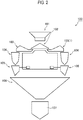
- FIG. 2 is a schematic view of the combination weighing apparatus 100.
- the combination weighing apparatus 100 may include a supply chute 101, a distribution table 102, a radial feeder 103, a pool hopper 104, a weighing hopper 105, a gathering chute 106, and a timing hopper 107.
- the combination weighing apparatus 100 weighs and conveys an article as a target to be weighed.
- the article is, for example, a food.
- Such articles are put into the supply chute 101, and then the articles put in the supply chute 101 are supplied to the distribution table 102.
- the distribution table 102 may convey the articles in a distributing manner.
- the distribution table 102 supplies the articles to a plurality of radial feeders 103 disposed around the distribution table 102.
- the radial feeders 103 each convey the article supplied from the distribution table 102, to the pool hopper 104 provided corresponding to the radial feeder 103.
- the "supply mechanism” according to the present invention may be adopted to at least either a supply chute 101 or a distribution table 102, and the “conveyance mechanism” according to the present invention may be adopted to a radial feeder 103.
- the conveyance mechanism according to the present embodiment is adopted to a radial feeder.
- the conveyance mechanism according to the present invention is not limited to a radial feeder and thus may be provided as a mechanism for a supply chute, a gathering chute, or a pool hopper in a combination weighing apparatus. The conveyance mechanism will be described in detail later.
- each pool hopper 104 may be received by the weighing hopper 105 disposed below the corresponding pool hopper 104.
- Each weighing hopper 105 is disposed downstream of the supply mechanism and temporarily stores the article in order to measure the weight of the article.
- a combination weighing operation may be performed on the basis of the weight value of the article weighted by each weighing hopper 105.
- a combination of articles may be selected such that the result of the combination weighing operation is in a predetermined allowable range and is closest to a target value.
- the articles in the weighing hoppers 105 included in the selected combination may be discharged to the gathering chute 106.
- the gathering chute 106 gathers the articles discharged from the plurality of weighing hoppers 105.
- the articles discharged to the gathering chute 106 may be supplied to the timing hopper 107.
- the timing hopper 107 may supply the articles to, for example, a packaging apparatus installed at the post stage of the conveyance mechanism 1.
- FIG. 3 is an exploded side view of the conveyance mechanism 1.
- FIG. 4 is an exploded plan view of the conveyance mechanism 1. Note that, for convenience of description, in FIG. 4 , only a second abutting member 21 is illustrated for a support member 20.
- FIG. 5 is a perspective view of the support member 20.
- the conveyance mechanism 1 according to the present embodiment is adopted to a radial feeder 103.
- the conveyance mechanism 1 may include a trough 10, the support member 20, and a coupling member 30.
- the trough 10 conveys an article.
- the trough 10 includes a conveyance face (conveyance member) 13 for conveyance of an article and a first abutting member 11 that is located on the back side of the conveyance face and abuts on the support member 20.
- the conveyance face 13 extends in the radial direction of the combination weighing apparatus 100 and guides an article to the weighing hopper 105 through the pool hopper 104.
- the first abutting member 11 may be plate-shaped and have an oval shape with a long-axis direction LD and a short-axis direction SD.
- first abutting member 11 is not necessarily plate-shaped and thus may be columnar or rectangularly parallelepipedic.
- the bottom face of the first abutting member 11 that is columnar may abut on the second abutting member 21.
- the first abutting member 11 is not necessarily oval and thus may be perfectly circular or rectangular in shape.
- the trough 10 is detachably coupled to the support member 20.
- the support member 20 includes the second abutting member 21 that abuts on the trough 10.
- the second abutting member 21 has a second circumferential edge 22 vertically identical to a first circumferential edge 12 that is the circumferential edge of the first abutting member 11.
- the second abutting member 21 may be plate-shaped and have an oval shape with a long-axis direction LD and a short-axis direction SD.
- the first circumferential edge 12 may be identical in shape to the second circumferential edge 22.
- the second abutting member 21 may include an abutting face 25 that abuts on the first abutting member 11, a non-abutting face 26 spaced apart from the first abutting member 11, and a wall 27 extending from the abutting face 25 to the non-abutting face 26, away from the first abutting member 11.
- the abutting face 25 is provided along the second circumferential edge 22, ranging over the entirety of the second circumferential edge 22.
- the non-abutting face 26 is spaced apart from the second circumferential edge 22 and is provided, in plan view, inside the abutting face 25.
- the non-abutting face 26 is surrounded with the abutting face 25 and is recessed below the abutting face 25.
- the circumferential edge of the non-abutting face 26 is similar in shape to the second circumferential edge 22.
- the wall 27 is interposed between the abutting face 25 and the non-abutting face 26.
- the support member 20 includes a vibrator 28 that vibrates the trough 10.
- the vibrator 28 is coupled to the opposite face to a face that the second abutting member 21 has closer to the first abutting member 11.
- the vibrator 28 is coupled to the lower face of the second abutting member 21.
- the support member 20 includes a waterproof cover 29 covering the coupled portion between the vibrator 28 and the second abutting member 21.
- the coupling member (fastening band) 30 couples the trough 10 and the support member 20, detachably.
- the coupling member 30 may include a first frame 31 and a second frame 32.
- the first frame 31 and the second frame 32 each cover half of the first circumferential edge 12 (half of the second circumferential edge 22).
- One end of the first frame 31 and one end of the second frame 32 are coupled pivotably.
- the coupling member 30 fastens the first circumferential edge 12 of the first abutting member 11 and the second circumferential edge 22 of the second abutting member 21 in vertical superposition.
- the coupling member 30 laterally fastens the circumferential edges with the first frame 31 and the second frame 32 and pressurizes the circumferential edges from above and from below. In this manner, the coupling member 30 couples the trough 10 and the support member 20 together.
- a user detaches the trough 10 and the coupling member 30 from the support member 20 and regularly cleanses the trough 10, the support member 20, and the coupling member 30.
- the support member 20 kept installed in the conveyance mechanism 1 is cleansed.
- the second abutting member 21 of the support member 20 is plate-shaped, extending planarly, and thus moisture due to cleansing remains easily thereon.
- the conveyance mechanism 1 according to the present embodiment has the second abutting member 21 enhanced in drainage in the support member 20. Next, the configuration of the second abutting member 21 enhanced in drainage will be described.
- the second abutting member 21 is provided with a through hole 23 passing through the second abutting member 21. Because the second abutting member 21 has the through hole 23, moisture on the second abutting member 21 that is plate-shaped can be discharged through the through hole 23, resulting in an enhancement in the drainage of the second abutting member 21.
- two through holes 23 are provided apart in the long-axis direction LD. However, this configuration is not limitative, the number of through holes 23 may be one or three or more. The through holes 23 may be provided apart in the short-axis direction SD.
- At least part of the through holes 23 may be provided at the non-abutting face 26. Note that part of the plurality of through holes 23 (e.g., one through hole) may be provided at the non-abutting face 26 or part of each through hole 23 may be provided at the non-abutting face 26.
- the non-abutting face 26 of the second abutting member 21 does not abut on the first abutting member 11, so that the first abutting member 11 does not occlude the through holes 23 of the non-abutting face 26. Because of the through holes 23 at least partially provided at the non-abutting face 26, even in the coupling state, moisture on the second abutting member 21 can be discharged through the through holes 23.
- the through holes 23 may be each provided astride the wall 27 and the non-abutting face 26.
- the wall 27 of the second abutting member 21 enables a rise in the rigidity of the second abutting member 21 because the wall 27 functions as a reinforcing rib. Therefore, even with the through holes 23 provided at the second abutting member 21, the second abutting member 21 can be inhibited from deforming, so that the function of supporting the trough 10 can be retained.
- each through hole 23 is astride side faces facing in different directions (the wall 27 and the non-abutting face 26), so that draining can be performed through the plurality of side faces, resulting in a further enhancement in drainage.
- the first abutting member 11 and the second abutting member 21 may each have an oval shape with a long-axis direction LD and a short-axis direction SD.
- first abutting member 11 and the second abutting member 21 are each perfectly circular in shape, because the first abutting member 11 and the second abutting member 21 are each oval in shape, mutual positioning is easier, resulting in an enhancement in operability at the time of coupling.
- At least part of the through holes 23 may be provided at the ends in the long-axis direction LD.
- the length in the long-axis direction LD of the second abutting member 21 is longer than the length in the short-axis direction SD of the second abutting member 21, and thus draining is likely to be difficult to perform over the entire region in the long-axis direction.
- the through holes 23 are provided at the ends in the long-axis direction LD, resulting in an easy enhancement in drainage over the entire region in the long-axis direction LD of the second abutting member 21.
- the second abutting member 21 is disposed at a slant from the horizontal direction HD.
- at least part of the through holes 23 may be disposed below the center 21C in the vertical direction of the second abutting member 21.
- Moisture on the second abutting member 21 is guided by gravity to the lower portion of the second abutting member 21.
- a through hole 23 is provided below the center 21C in the vertical direction of the second abutting member 21, so that the moisture guided downward can be discharged through the through hole 23.
- one of the through holes 23 is disposed below the center 21C in the vertical direction of the second abutting member 21 and the other through hole 23 is disposed above the center 21C in the vertical direction of the second abutting member 21.
- the plurality of through holes 23 is disposed apart in the vertical direction across the center 21C in the vertical direction of the second abutting member 21, so that draining can be performed a plurality of times in the process of downward guiding of moisture on the second abutting member 21, resulting in a further enhancement in drainage.
- the through holes 23 may be provided closer to the second circumferential edge 22 than to the region overlapping the waterproof cover 29. That is, in plan view, the through holes 23 may be provided outside the waterproof cover 29. Moisture remaining on the second abutting member 21 can be discharged outside the waterproof cover 29 covering the vibrator 28 without being discharged in the waterproof cover 29. Thus, an enhancement can be made in drainage on the second abutting member 21 with a waterproof guarantee on the waterproof cover 29.
- Such conveyance mechanisms 1 are used in the combination weighing apparatus 100 and each causes an article supplied from the supply mechanism, to be conveyed to the corresponding weighing hopper 105.
- the second abutting member 21 enhanced in drainage in the support member 20 in each conveyance mechanism 1 enables the trough 10 to hygienically conveys an article to be conveyed.
- the combination weighing apparatus 100 including the conveyance mechanisms 1 can acquire an aggregate of articles weighed as a predetermined value with a hygienic guarantee on articles.
- FIG. 6 is an exploded plan view of the conveyance mechanism 1. Note that, in FIG. 6 , for convenience of description, only the second abutting member 21 is illustrated for the support member 20.
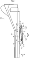
- FIG. 7 is a schematic side view of the trough 10.
- FIG. 8 is a perspective view of the coupling member 30.
- the conveyance face 13 and the first abutting plate member 11 are individually produced, and then the conveyance face 13 and the first abutting member 11 are coupled by the coupling member 30, so that the trough 10 can be produced.
- the coupled portion between each member is continuously welded in order to prevent moisture from coming inside the conveyance mechanism 1 at the time of cleansing of the conveyance mechanism 1.
- the conveyance mechanism 1 according to the present embodiment enables easily continuous welding of the coupling member 30 that couples the conveyance face 13 and the first abutting member 11 in the trough 10.
- the configuration of the coupling member 30 enhanced in operability at the time of welding will be described.
- the coupling member 30 is circular in section. That is the coupling member 30 may be columnar or cylindrical in shape. As illustrated in FIG. 8 , the coupling member 30 according to the present embodiment is cylindrical in shape, having an inner circumferential face and an outer circumferential face 34.
- the coupling member 30 includes a wall 33 extending in the axial direction of the coupling member 30 circular in section, an upper-end face 35 that is located at the upper end of the wall 33 and abuts on the conveyance face 13, and a lower-end face 36 that is located at the lower end of the wall 33 and abuts on the support member 20.
- At least either the upper-end face 35 or the lower-end face 36 is a non-perpendicular end face that has an oval shape with a long-axis direction LD and a short-axis direction SD and is non-perpendicular in angle to the outer circumferential face 34 of the wall 33.
- the angle to the outer circumferential face of the wall 33 may be the angle to the outer circumferential face in sectional view along the long-axis direction LD (section illustrated in FIG. 7 ) or may be the angle to the outer circumferential face in sectional view along the short-axis direction SD. That is the angle to any part of the outer circumferential face of the wall 33 is at least required.
- the upper-end face 35 and the lower-end face 36 each have an angle different from 90 degrees to the outer circumferential face.
- the upper-end face 35 and the lower-end face 36 are each a non-perpendicular end face.
- either the upper-end face 35 or the lower-end face 36 may be a non-perpendicular end face.
- the non-perpendicular end face is non-perpendicular in angle to the outer circumferential face of the wall 33, namely, has an angle different from 90 degrees.
- the non-perpendicular end face has an angle different from 90 degrees to the outer circumferential face, and has a larger sectional area, in comparison to a mode in which the angle to the outer circumferential face is 90 degrees.
- a larger sectional area of the non-perpendicular end face facilitates access to the juncture of the non-perpendicular end face, so that the juncture is continuously welded easily.
- a larger sectional area of the non-perpendicular end face enables securing of the juncture in length, so that a rise can be made in juncture strength.
- junctures 14 of the coupling member 30 are each surrounded and indicated with a dot-and-dash line.
- the length in the long-axis direction LD can be secured long.
- the long-axis direction LD is disposed corresponding to a portion to which it is difficult to put a welding torch, so that an enhancement can be made in the accessibility of the welding torch.
- the sectional shape of the coupling member 30 at 90 degrees to the outer circumferential face 34 of the wall 33 may be perfectly circular.
- FIG. 8 the sectional shape of the coupling member 30 at 90 degrees to the outer circumferential face 34 of the wall 33 is indicated with chain double dashed lines.
- diagonally cutting a cylinder perfectly circular in shape or a column perfectly circular in shape enables acquisition of a non-perpendicular end face oval in shape.
- An appropriate change in cutting angle enables appropriate setting of the aspect ratio of an oval shape, so that the coupling member 30 having a sectional shape having a desired aspect ratio can be acquired.
- the long-axis direction LD of the non-perpendicular end face may be non-perpendicular to the outer circumferential face 34 of the wall 33. Because the long-axis direction LD of the non-perpendicular end face is non-perpendicular to the outer circumferential face 34, the wall 33 extends at a slant from the long-axis direction LD instead of extending perpendicularly to the long-axis direction LD. Therefore, the position of the upper-end face 35 located at the upper end of the wall 33 and the position of the lower-end face 36 located at the lower end of the wall 33 are not identical in the long-axis direction LD. Thus, in comparison to a configuration in which the position of the upper-end face 35 and the position of the lower-end face 36 are identical, the leading end of the welding torch is inserted easier, so that the junctures are continuously welded easier.
- the upper-end face 35 and the lower-end face 36 are each a non-perpendicular end face.
- the upper-end face 35 in the long-axis direction LD and the lower-end face 36 in the long-axis direction LD are not parallel.
- the distance between the upper-end face 35 and the lower-end face 36 on one end side in the long-axis direction LD is different from the distance between the upper-end face 35 and the lower-end face 36 on the other end side in the long-axis direction LD. As illustrated in FIG.
- the wall 33 in a section along the long-axis direction LD and the vertical direction VD, the wall 33 includes a first wall 37 located on one side in the long-axis direction LD and a second wall 38 located on the other side in the long-axis direction LD.
- the length H27 in the vertical direction VD of the first wall 37 is longer than the length H28 in the vertical direction VD of the second wall 38.
- the length L28 in the long-axis direction LD of the second wall 38 is shorter than the length L27 in the long-axis direction LD of the first wall 37. Therefore, in FIG. 7 , the left wall located on the left is the first wall 37 and the right wall on the right is the second wall 38.
- a first upper angle ⁇ 11 between the outer circumferential face 34 of the first wall 37 and an upper-end imaginary line XL extending outward from the upper-end face 35 in the long-axis direction LD along the upper-end face 35 is acute.
- a second upper angle ⁇ 21 between the outer circumferential face 34 of the second wall 38 and the upper-end imaginary line XL is obtuse.
- a first lower angle ⁇ 12 between the outer circumferential face 34 of the first wall 37 and a lower-end imaginary line YL extending outward from the lower-end face 36 in the long-axis direction LD along the lower-end face 36 is obtuse.
- a second lower angle ⁇ 22 between the outer circumferential face 34 of the second wall 38 and the lower-end imaginary line YL is acute. Because the first upper angle ⁇ 11 between the outer circumferential face 34 of the first wall 37 and the upper-end imaginary line XL is acute, the angle between the first wall 37 and the conveyance face 13 is small.
- the upper-end face of the outer circumferential face 34 of the first wall 37 at the first upper angle ⁇ 11 is located, in the long-axis direction, inside the lower-end face of the outer circumferential face 34 of the first wall 37 at the first lower angle ⁇ 12, causing inconvenience in the accessibility of the welding torch.
- the length H27 in the vertical direction VD of the first wall 37 is long, causing a wide space between the members even with a small angle between the members.
- an enhancement can be made in the accessibility of the welding torch. Because the second lower angle ⁇ 22 between the outer circumferential face 34 of the second wall 38 and the lower-end imaginary line YL is acute, the angle between the second wall 38 and the first abutting member 11 is small.
- the lower-end face of the outer circumferential face 34 of the second wall 38 at the second lower angle ⁇ 22 is located, in the long-axis direction, inside the upper-end face of the outer circumferential face 34 of the second wall 38 at the second upper angle ⁇ 21, causing inconvenience in the accessibility of the welding torch.
- the length L28 in the long-axis direction LD of the second wall 38 is short, so that the length by which the juncture 14 is recessed inside in the long-axis direction LD is relatively short. That is the length by which the welding torch is inserted can be shortened. Thus, even with a small angle between the members and a narrow space between the members, the juncture is continuously welded easily with the leading end of the welding torch in contact with the juncture.
- the coupling member 30 is joined to both of the first abutting member 11 and the conveyance face 13.
- the coupling member 30 is not particularly limited in joining order. Preferably, a relatively large area of member is joined and then a relatively small area of member is joined. In comparison to a case where a large area of member is welded and then a small area of member is welded, an enhancement can be made in the accessibility of the welding torch in the latter half of welding work. According to the present embodiment, the area of the first abutting member 11 is smaller than the area of the conveyance face 13. Thus, the first abutting member 11 may be joined to the coupling member 30 after the conveyance face 13 is joined to the coupling member 30.
- Either the upper-end face 35 or the lower-end face 36 is required to be a non-perpendicular end face.
- troughs 10A and 10B in the following configurations are similar to that in the configuration described above.
- Each following configuration will be given with a third wall 53 and a fourth wall 54 or a fifth wall 55 and a sixth wall 56 instead of the first wall 37 and the second wall 38 in the configuration described above.
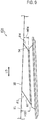
- FIG. 9 is a schematic side view of the trough 10A.
- a wall includes the third wall 53 and the fourth wall 54 shorter in length in the vertical direction VD than the third wall 53. That is the length H53 in the vertical direction VD of the third wall 53 is longer than the length H54 in the vertical direction VD of the fourth wall 54.
- the wall located on the left in FIG. 9 is the third wall 53 and the wall located on the right in FIG. 9 is the fourth wall 54.
- An upper-end face 35 is a non-perpendicular end face.
- a third angle ⁇ 3 between the outer circumferential face of the third wall 53 and a long-axis imaginary line EL extending outward from the non-perpendicular end face (upper-end face 35) in the long-axis direction LD along the non-perpendicular end face is acute.
- a fourth angle ⁇ 4 between the outer circumferential face of the fourth wall 54 and the long-axis imaginary line EL is obtuse. Because the third angle ⁇ 3 between the outer circumferential face of the third wall 53 and the long-axis imaginary line EL is acute, the angle between the members (the third wall 53 and the conveyance face 13) is small.
- the upper-end face of the outer circumferential face of the third wall 53 at the third angle ⁇ 3 is located, in the long-axis direction, inside the lower-end face of the outer circumferential face of the third wall 53, causing inconvenience in the accessibility of the welding torch.
- the length H53 in the vertical direction VD of the third wall 53 is long, causing a wide space between the members even with a small angle between the members.
- an enhancement can be made in the accessibility of the welding torch.
- a long length in the vertical direction of the wall (a long distance between the first abutting member 11 and the conveyance face 13) enables an enhancement in the accessibility of the welding torch.
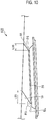
- FIG. 10 is a schematic side view of the trough 10B.
- a wall includes the fifth wall 55 and the sixth wall 56 shorter in length in the long-axis direction LD than the fifth wall 55. That is the length L55 in the long-axis direction LD of the fifth wall 55 is longer than the length L56 in the long-axis direction LD of the sixth wall 56.
- the wall located on the left in FIG. 10 is the fifth wall 55 and the wall located on the right in FIG. 10 is the sixth wall 56.
- a lower-end face 36 is a non-perpendicular end face.
- a fifth angle ⁇ 5 between the outer circumferential face of the fifth wall 55 and a long-axis imaginary line EL extending outward from the non-perpendicular end face in the long-axis direction LD along the non-perpendicular end face is obtuse.
- a sixth angle ⁇ 6 between the outer circumferential face of the sixth wall 56 and the long-axis imaginary line EL is acute. Because the sixth angle ⁇ 6 between the outer circumferential face of the sixth wall 56 and the long-axis imaginary line EL is acute, the angle between the members (the sixth wall 56 and the first abutting member 11) is small.
- the lower-end face of the outer circumferential face of the sixth wall 56 at the sixth angle ⁇ 6 is located, in the long-axis direction LD, inside the upper-end face of the outer circumferential face of the sixth wall 56, causing inconvenience in the accessibility of the welding torch.
- the length L56 in the long-axis direction LD of the sixth wall 56 is short, so that the length by which the juncture 14 is recessed inside in the long-axis direction LD is relatively short. That is the length by which the welding torch is inserted can be shortened.
- the juncture 14 is continuously welded easily with the leading end of the welding torch in contact with the juncture 14.
- a short length in the long-axis direction LD of the wall allows the length by which the welding torch is inserted to be shortened, resulting in retention of the accessibility of the welding torch.
- Such conveyance mechanisms 1 are used in the combination weighing apparatus 100 and each causes an article supplied from the supply mechanism, to be conveyed to the corresponding weighing hopper 105.
- the junctures 14 in the troughs 10, 10A, and 10B are continuously welded in order to prevent moisture from coming inside from around, so that the troughs 10, 10A, and 10B can each hygienically convey an article to be conveyed.
- the combination weighing apparatus 100 including the conveyance mechanisms 1 can acquire an aggregate of articles weighed as a predetermined value with a hygienic guarantee on articles.
- a conveyance mechanism includes: a trough (10) that conveys an article; a support member (30) to which the trough is detachably coupled, the support member including a vibrator that vibrates the trough.
- the trough includes a conveyance member (12) that conveys the article; a plate member (11) that abuts on the support member; and a coupling member (20) that couples the conveyance member (12) and the plate member (11).
- the coupling member (20) has a circular shape in section and includes: a wall (23) extending in an axial direction of the circular shape; an upper-end face (25) that is located at an upper end of the wall and abuts on the conveyance member (12); and a lower-end face (26) that is located at a lower end of the wall and abuts on the support member (30).
- At least either the upper-end face or the lower-end face is a non-perpendicular end face that has an oval shape with a long-axis direction (LD) and a short-axis direction (SD) and is non-perpendicular in angle to an outer circumferential face of the wall.
- LD long-axis direction
- SD short-axis direction
- the non-perpendicular end face is non-perpendicular in angle to the outer circumferential face of the wall, namely, has an angle different from 90 degrees.
- the non-perpendicular end face has an angle different from 90 degrees to the outer circumferential face, and has a larger sectional area, in comparison to a mode in which the angle to the outer circumferential face is 90 degrees.
- a larger sectional area of the non-perpendicular end face facilitates access to the juncture of the non-perpendicular end face, so that the juncture is continuously welded easily.
- a larger sectional area of the non-perpendicular end face enables securing of the juncture in length, so that a rise can be made in juncture strength.
- the length in the long-axis direction can be secured long.
- a long-axis portion is disposed corresponding to a portion to which it is difficult to put the welding torch, so that an enhancement can be made in the accessibility of the welding torch.
- a sectional shape of the coupling member at 90 degrees to the outer circumferential face of the wall is perfectly circular, and the long-axis direction (LD) of the non-perpendicular end face is non-perpendicular to the outer circumferential face of the wall.
- the sectional shape at 90 degrees to the outer circumferential face of the wall is perfectly circular, and diagonally cutting a cylinder perfectly circular in shape or a column perfectly circular in shape enables acquisition of a non-perpendicular end face oval in shape.
- An appropriate change in cutting angle enables appropriate setting of the aspect ratio of an oval shape, so that the coupling member having a sectional shape having a desired aspect ratio can be acquired.
- the position of the upper-end face located at the upper end of the wall and the position of the lower-end face located at the lower end of the wall are not identical in the long-axis direction.
- the leading end of the welding torch is inserted easier, so that the junctions are continuously welded easier.
- the wall in a section along the long-axis direction and a vertical direction, includes a first wall (27) located on one side in the long-axis direction and a second wall (28) located on another side in the long-axis direction, the upper-end face and the lower-end face are each the non-perpendicular end face, a first upper angle ( ⁇ 11) between an outer circumferential face of the first wall and an upper-end imaginary line (XL) extending outward from the upper-end face in the long-axis direction along the upper-end face is acute, a second upper angle ( ⁇ 21) between an outer circumferential face of the second wall and the upper-end imaginary line is obtuse, a first lower angle ( ⁇ 12) between the outer circumferential face of the first wall and a lower-end imaginary line (YL) extending outward from the lower-end face in the long-axis direction along the lower-end face is obtuse, a second lower angle ( ⁇ 22) between the outer circumferential face
- the first upper angle between the outer circumferential face of the first wall and the upper-end imaginary line is acute, so that the angle between the first wall and the conveyance member is small.
- the length (H27) in the vertical direction of the first wall is long, causing a wide space between the members even with a small angle between the members.
- an enhancement can be made in the accessibility of the welding torch.
- the second lower angle between the outer circumferential face of the second wall and the lower-end imaginary line is acute, so that the angle between the second wall and the plate member is small.
- the length (L28) in the long-axis direction of the second wall is short, so that the length by which the juncture is recessed inside in the long-axis direction is relatively short.
- the length by which the welding torch is inserted can be shortened.
- the juncture is continuously welded easily with the leading end of the welding torch in contact with the juncture.
- the wall in a section along the long-axis direction and a vertical direction, includes a third wall (53) located on one side in the long-axis direction and a fourth wall (54) that is located on another side in the long-axis direction and is shorter in length in the vertical direction than the third wall.
- a third angle ( ⁇ 3) between an outer circumferential face of the third wall and a long-axis imaginary line (EL) extending outward from the non-perpendicular end face in the long-axis direction along the non-perpendicular end face is acute
- a fourth angle ( ⁇ 4) between an outer circumferential face of the fourth wall and the long-axis imaginary line (EL) is obtuse.
- the third angle between the outer circumferential face of the third wall and the long-axis imaginary line is acute, so that the angle between the members (the third wall and the conveyance member or the third wall and the plate member) is small.
- the length (H53) in the vertical direction of the third wall is long, causing a wide space between the members even with a small angle between the members.
- an enhancement can be made in the accessibility of the welding torch.
- the wall in a section along the long-axis direction and a vertical direction, includes a fifth wall (55) located on one side in the long-axis direction and a sixth wall (56) that is located on another side in the long-axis direction and is shorter in length in the long-axis direction than the fifth wall.
- a fifth angle ( ⁇ 5) between an outer circumferential face of the fifth wall and a long-axis imaginary line (EL) extending outward from the non-perpendicular end face in the long-axis direction along the non-perpendicular end face is obtuse
- a sixth angle ( ⁇ 6) between an outer circumferential face of the sixth wall and the long-axis imaginary line (EL) is acute.
- the sixth angle between the outer circumferential face of the sixth wall and the long-axis imaginary line is acute, so that the angle between the members (the sixth wall and the conveyance member or the sixth wall and the plate member) is small.
- the length (L56) in the long-axis direction of the sixth wall is short, so that the length by which the juncture is recessed inside in the long-axis direction is relatively short. That is the length by which the welding torch is inserted can be shortened.
- the juncture is continuously welded easily with the leading end of the welding torch in contact with the juncture.
- a combination weighing apparatus includes: a plurality of the above conveyance mechanisms (1); a supply mechanism of supplying articles; a plurality of weighing hoppers (105) that is provided downstream of the supply mechanism and each temporarily stores an article in order to measure a weight of the article; and a gathering chute (106) that gathers the articles discharged from the plurality of weighing hoppers.
- the plurality of the conveyance mechanisms conveys the articles supplied from the supply mechanism, to the plurality of weighing hoppers.
- the junctures in each trough are continuously welded in order to prevent moisture from coming inside from around, so that each trough can hygienically convey an article to be conveyed.
- acquired can be an aggregate of articles weighed as a predetermined value with a hygienic guarantee on articles.
Landscapes
- Engineering & Computer Science (AREA)
- Mechanical Engineering (AREA)
- Physics & Mathematics (AREA)
- General Physics & Mathematics (AREA)
- Jigging Conveyors (AREA)
- Feeding Of Articles To Conveyors (AREA)
- Filling Or Emptying Of Bunkers, Hoppers, And Tanks (AREA)
Abstract
Description
- The present invention relates to a conveyance mechanism of conveying an article, and relates particularly to a conveyance mechanism for use in a combination weighing apparatus including a plurality of weighing hoppers.
-
JP 2017-26339 A - The conveyance mechanism in
JP 2017-26339 A - At the time of cleansing of such a conveyance mechanism, generally, the trough is cleansed and additionally the support member is cleansed with the trough detached therefrom. In this case, the support member kept installed in the conveyance mechanism is cleansed. The second plate of the support member is plate-shaped, extending planarly, and thus moisture due to cleansing remains easily thereon. Thus, at the time of reassembly, the moisture is likely to remain on the second plate. Assembly with moisture remaining on the second plate causes unhygienic fears, such as moisture degradation and leakage. In particular, a conveyance mechanism of conveying a food as an article requires a hygienic guarantee with an enhancement in the drainage of the support member.
- Therefore, an object of the present invention is to provide a plate-shaped abutting member enhanced in drainage in a support member that supports a trough that conveys an article.
- A conveyance mechanism according to an aspect includes: a trough (10) that conveys an article; a support member (20) to which the trough is detachably coupled, the support member including a vibrator that vibrates the trough; and a coupling member that couples the trough and the support member. The trough includes a first abutting member (11) that is located on a back side of a conveyance face for conveyance of the article and abuts on the support member. The support member includes a second abutting member (21) that is plate-shaped and has a second circumferential edge (22) vertically identical to a first circumferential edge (12) that is a circumferential edge of the first abutting member. The coupling member couples the trough and the support member by fastening the first abutting member and the second abutting member with the first circumferential edge and the second circumferential edge in superposition. The second abutting member (21) is provided with a through hole (23) passing through the second abutting member. According to the present aspect, the second abutting member of the support member has the through hole, so that moisture on the second abutting member that is plate-shaped can be discharged through the through hole, resulting in an enhancement in the drainage of the second abutting member.
- According to a preferred aspect, the second abutting member includes, in a coupling state where the second abutting member is coupled to the first abutting member by the coupling member, an abutting face (25) abutting on the first abutting member and a non-abutting face (26) spaced apart from the first abutting member. At least part of the through hole is provided at the non-abutting face. According to the present aspect, in the coupling state, the non-abutting face of the second abutting member does not abut on the first abutting member, so that the first abutting member does not occlude the through hole of the non-abutting face. Thus, even in the coupling state, moisture on the second abutting member can be discharged through the through hole.
- According to a preferred aspect, the second abutting member includes a wall (27) extending from the abutting face to the non-abutting face, away from the first abutting member. At least part of the through hole is provided astride the wall and the non-abutting face. According to the present aspect, the wall functions as a reinforcing rib, resulting in a rise in the rigidity of the second abutting member, in comparison to a mode in which the entirety of the second abutting member is smoothly plate-shaped. Therefore, even with the through hole provided at the second abutting member, the second abutting member can be inhibited from deforming, so that the function of supporting the trough can be retained. In addition, the through hole is astride side faces facing in different directions (the wall and the non-abutting face), so that draining can be performed through the plurality of side faces, resulting in a further enhancement in drainage.
- According to a preferred aspect, the first abutting member and the second abutting member have an oval shape with a long-axis direction (LD) and a short-axis direction (SD). At least part of the through hole is provided at an end in the long-axis direction of the second abutting member. According to the present aspect, because the first abutting member and the second abutting member are each oval in shape, mutual positioning is easier, resulting in an enhancement in operability at the time of coupling, in comparison to a configuration in which the first abutting member and the second abutting member are each perfectly circular in shape. The through hole is provided at the end in the long-axis direction of the oval shape, resulting in an easy enhancement in drainage over the entire region in the long-axis direction of the second abutting member.
- According to a preferred aspect, the second abutting member is disposed at a slant from a horizontal direction (HD). At least part of the through hole is disposed below a center in a vertical direction of the second abutting member. According to the present aspect, moisture on the second abutting member is guided to the lower portion of the second abutting member. The through hole is provided below the center in the vertical direction of the second abutting member, so that the moisture guided downward can be discharged through the through hole.
- According to a preferred aspect, the vibrator (28) is coupled to a face opposite to a face that the second abutting member has closer to the first abutting member. The support member includes a waterproof cover (29) covering a coupled portion between the vibrator and the second abutting member. The through hole is provided closer to the second circumferential edge than to a region overlapping the waterproof cover. According to the present aspect, moisture remaining on the second abutting member can be discharged outside the waterproof cover covering the vibrator without being discharged in the waterproof cover. Thus, an enhancement can be made in drainage on the second abutting member with a waterproof guarantee on the waterproof cover.
- A combination weighing apparatus according to an aspect includes: a plurality of the above conveyance mechanisms; a supply mechanism of supplying articles; a plurality of weighing hoppers that is provided downstream of the supply mechanism and each temporarily stores an article in order to measure a weight of the article; and a gathering chute that gathers the articles discharged from the plurality of weighing hoppers. The plurality of the conveyance mechanisms conveys the articles supplied from the supply mechanism, to the plurality of weighing hoppers. According to the present aspect, each trough hygienically conveys an article to be conveyed. Thus, acquired can be an aggregate of articles weighed as a predetermined value with a hygienic guarantee on articles.
-
-
FIG. 1 is an entire perspective view of a combination weighing apparatus; -
FIG. 2 is a schematic view of the combination weighing apparatus; -
FIG. 3 is an exploded side view of a conveyance mechanism; -
FIG. 4 is an exploded plan view of the conveyance mechanism; -
FIG. 5 is a perspective view of a support member; -
FIG. 6 is an exploded plan view of the conveyance mechanism; -
FIG. 7 is a side view of a trough; -
FIG. 8 is a perspective view of a coupling member; -
FIG. 9 is a schematic side view of a trough; and -
FIG. 10 is a schematic side view of a trough. - A
conveyance mechanism 1 and acombination weighing apparatus 100 according to an embodiment will be described below with reference to the drawings. Note that, in the following drawings, the same or similar parts are denoted with the same or similar reference signs. It should be noted that the drawings are schematic and, for example, the ratio between each dimension is different from the real in some cases. Therefore, for example, specific dimensions should be understood in consideration of the following descriptions. In addition, in some cases, parts between the drawings are different in the relationship or ratio between mutual dimensions. - An embodiment of the present invention will be described below with reference to
FIGS. 1 to 5 .FIG. 1 is an entire perspective view of thecombination weighing apparatus 100.FIG. 2 is a schematic view of thecombination weighing apparatus 100. Thecombination weighing apparatus 100 may include asupply chute 101, a distribution table 102, aradial feeder 103, apool hopper 104, a weighinghopper 105, a gatheringchute 106, and atiming hopper 107. - The
combination weighing apparatus 100 weighs and conveys an article as a target to be weighed. The article is, for example, a food. Such articles are put into thesupply chute 101, and then the articles put in thesupply chute 101 are supplied to the distribution table 102. The distribution table 102 may convey the articles in a distributing manner. The distribution table 102 supplies the articles to a plurality ofradial feeders 103 disposed around the distribution table 102. Theradial feeders 103 each convey the article supplied from the distribution table 102, to thepool hopper 104 provided corresponding to theradial feeder 103. Note that the "supply mechanism" according to the present invention may be adopted to at least either asupply chute 101 or a distribution table 102, and the "conveyance mechanism" according to the present invention may be adopted to aradial feeder 103. Note that the conveyance mechanism according to the present embodiment is adopted to a radial feeder. However, the conveyance mechanism according to the present invention is not limited to a radial feeder and thus may be provided as a mechanism for a supply chute, a gathering chute, or a pool hopper in a combination weighing apparatus. The conveyance mechanism will be described in detail later. - The article supplied to each
pool hopper 104 may be received by the weighinghopper 105 disposed below the correspondingpool hopper 104. Each weighinghopper 105 is disposed downstream of the supply mechanism and temporarily stores the article in order to measure the weight of the article. On the basis of the weight value of the article weighted by each weighinghopper 105, a combination weighing operation may be performed. A combination of articles may be selected such that the result of the combination weighing operation is in a predetermined allowable range and is closest to a target value. The articles in the weighinghoppers 105 included in the selected combination may be discharged to thegathering chute 106. The gatheringchute 106 gathers the articles discharged from the plurality of weighinghoppers 105. The articles discharged to thegathering chute 106 may be supplied to thetiming hopper 107. Thetiming hopper 107 may supply the articles to, for example, a packaging apparatus installed at the post stage of theconveyance mechanism 1. - Next, the
conveyance mechanism 1 will be described in detail on the basis ofFIGS. 3 to 5 .FIG. 3 is an exploded side view of theconveyance mechanism 1.FIG. 4 is an exploded plan view of theconveyance mechanism 1. Note that, for convenience of description, inFIG. 4 , only a second abuttingmember 21 is illustrated for asupport member 20.FIG. 5 is a perspective view of thesupport member 20. As described above, theconveyance mechanism 1 according to the present embodiment is adopted to aradial feeder 103. - The
conveyance mechanism 1 may include atrough 10, thesupport member 20, and acoupling member 30. Thetrough 10 conveys an article. Thetrough 10 includes a conveyance face (conveyance member) 13 for conveyance of an article and a first abuttingmember 11 that is located on the back side of the conveyance face and abuts on thesupport member 20. Theconveyance face 13 extends in the radial direction of thecombination weighing apparatus 100 and guides an article to the weighinghopper 105 through thepool hopper 104. The first abuttingmember 11 may be plate-shaped and have an oval shape with a long-axis direction LD and a short-axis direction SD. Note that the first abuttingmember 11 is not necessarily plate-shaped and thus may be columnar or rectangularly parallelepipedic. For example, the bottom face of the first abuttingmember 11 that is columnar may abut on the second abuttingmember 21. The first abuttingmember 11 is not necessarily oval and thus may be perfectly circular or rectangular in shape. - The
trough 10 is detachably coupled to thesupport member 20. Thesupport member 20 includes the second abuttingmember 21 that abuts on thetrough 10. The second abuttingmember 21 has a secondcircumferential edge 22 vertically identical to a firstcircumferential edge 12 that is the circumferential edge of the first abuttingmember 11. The second abuttingmember 21 may be plate-shaped and have an oval shape with a long-axis direction LD and a short-axis direction SD. The firstcircumferential edge 12 may be identical in shape to the secondcircumferential edge 22. - In the coupling state where the second abutting
member 21 is coupled to the first abuttingmember 11 by thecoupling member 30, the second abuttingmember 21 may include an abuttingface 25 that abuts on the first abuttingmember 11, anon-abutting face 26 spaced apart from the first abuttingmember 11, and awall 27 extending from the abuttingface 25 to thenon-abutting face 26, away from the first abuttingmember 11. The abuttingface 25 is provided along the secondcircumferential edge 22, ranging over the entirety of the secondcircumferential edge 22. Thenon-abutting face 26 is spaced apart from the secondcircumferential edge 22 and is provided, in plan view, inside the abuttingface 25. Thenon-abutting face 26 is surrounded with the abuttingface 25 and is recessed below the abuttingface 25. The circumferential edge of thenon-abutting face 26 is similar in shape to the secondcircumferential edge 22. Thewall 27 is interposed between the abuttingface 25 and thenon-abutting face 26. - The
support member 20 includes avibrator 28 that vibrates thetrough 10. Thevibrator 28 is coupled to the opposite face to a face that the second abuttingmember 21 has closer to the first abuttingmember 11. In other words, thevibrator 28 is coupled to the lower face of the second abuttingmember 21. Thesupport member 20 includes awaterproof cover 29 covering the coupled portion between thevibrator 28 and the second abuttingmember 21. - The coupling member (fastening band) 30 couples the
trough 10 and thesupport member 20, detachably. Thecoupling member 30 may include afirst frame 31 and asecond frame 32. Thefirst frame 31 and thesecond frame 32 each cover half of the first circumferential edge 12 (half of the second circumferential edge 22). One end of thefirst frame 31 and one end of thesecond frame 32 are coupled pivotably. Thecoupling member 30 fastens the firstcircumferential edge 12 of the first abuttingmember 11 and the secondcircumferential edge 22 of the second abuttingmember 21 in vertical superposition. More specifically, with the firstcircumferential edge 12 and the secondcircumferential edge 22 in superposition, thecoupling member 30 laterally fastens the circumferential edges with thefirst frame 31 and thesecond frame 32 and pressurizes the circumferential edges from above and from below. In this manner, thecoupling member 30 couples thetrough 10 and thesupport member 20 together. - For a hygienic guarantee on the
conveyance mechanism 1 having such a configuration, a user detaches thetrough 10 and thecoupling member 30 from thesupport member 20 and regularly cleanses thetrough 10, thesupport member 20, and thecoupling member 30. In this case, thesupport member 20 kept installed in theconveyance mechanism 1 is cleansed. The second abuttingmember 21 of thesupport member 20 is plate-shaped, extending planarly, and thus moisture due to cleansing remains easily thereon. Theconveyance mechanism 1 according to the present embodiment has the second abuttingmember 21 enhanced in drainage in thesupport member 20. Next, the configuration of the second abuttingmember 21 enhanced in drainage will be described. - The second abutting
member 21 is provided with a throughhole 23 passing through the second abuttingmember 21. Because the second abuttingmember 21 has the throughhole 23, moisture on the second abuttingmember 21 that is plate-shaped can be discharged through the throughhole 23, resulting in an enhancement in the drainage of the second abuttingmember 21. According to the present embodiment, two throughholes 23 are provided apart in the long-axis direction LD. However, this configuration is not limitative, the number of throughholes 23 may be one or three or more. The through holes 23 may be provided apart in the short-axis direction SD. - At least part of the through
holes 23 may be provided at thenon-abutting face 26. Note that part of the plurality of through holes 23 (e.g., one through hole) may be provided at thenon-abutting face 26 or part of each throughhole 23 may be provided at thenon-abutting face 26. In the coupling state, thenon-abutting face 26 of the second abuttingmember 21 does not abut on the first abuttingmember 11, so that the first abuttingmember 11 does not occlude the throughholes 23 of thenon-abutting face 26. Because of the throughholes 23 at least partially provided at thenon-abutting face 26, even in the coupling state, moisture on the second abuttingmember 21 can be discharged through the through holes 23. - The through holes 23 may be each provided astride the
wall 27 and thenon-abutting face 26. In comparison to a mode in which the entirety of the second abuttingmember 21 is smoothly plate-shaped, thewall 27 of the second abuttingmember 21 enables a rise in the rigidity of the second abuttingmember 21 because thewall 27 functions as a reinforcing rib. Therefore, even with the throughholes 23 provided at the second abuttingmember 21, the second abuttingmember 21 can be inhibited from deforming, so that the function of supporting thetrough 10 can be retained. In addition, each throughhole 23 is astride side faces facing in different directions (thewall 27 and the non-abutting face 26), so that draining can be performed through the plurality of side faces, resulting in a further enhancement in drainage. - The first abutting
member 11 and the second abuttingmember 21 may each have an oval shape with a long-axis direction LD and a short-axis direction SD. In comparison to a configuration in which the first abuttingmember 11 and the second abuttingmember 21 are each perfectly circular in shape, because the first abuttingmember 11 and the second abuttingmember 21 are each oval in shape, mutual positioning is easier, resulting in an enhancement in operability at the time of coupling. At least part of the throughholes 23 may be provided at the ends in the long-axis direction LD. The length in the long-axis direction LD of the second abuttingmember 21 is longer than the length in the short-axis direction SD of the second abuttingmember 21, and thus draining is likely to be difficult to perform over the entire region in the long-axis direction. However, the throughholes 23 are provided at the ends in the long-axis direction LD, resulting in an easy enhancement in drainage over the entire region in the long-axis direction LD of the second abuttingmember 21. - As illustrated in
FIG. 3 , the second abuttingmember 21 is disposed at a slant from the horizontal direction HD. Thus, at least part of the throughholes 23 may be disposed below thecenter 21C in the vertical direction of the second abuttingmember 21. Moisture on the second abuttingmember 21 is guided by gravity to the lower portion of the second abuttingmember 21. A throughhole 23 is provided below thecenter 21C in the vertical direction of the second abuttingmember 21, so that the moisture guided downward can be discharged through the throughhole 23. According to the present embodiment, one of the throughholes 23 is disposed below thecenter 21C in the vertical direction of the second abuttingmember 21 and the other throughhole 23 is disposed above thecenter 21C in the vertical direction of the second abuttingmember 21. The plurality of throughholes 23 is disposed apart in the vertical direction across thecenter 21C in the vertical direction of the second abuttingmember 21, so that draining can be performed a plurality of times in the process of downward guiding of moisture on the second abuttingmember 21, resulting in a further enhancement in drainage. - The through holes 23 may be provided closer to the second
circumferential edge 22 than to the region overlapping thewaterproof cover 29. That is, in plan view, the throughholes 23 may be provided outside thewaterproof cover 29. Moisture remaining on the second abuttingmember 21 can be discharged outside thewaterproof cover 29 covering thevibrator 28 without being discharged in thewaterproof cover 29. Thus, an enhancement can be made in drainage on the second abuttingmember 21 with a waterproof guarantee on thewaterproof cover 29. - As described above,
such conveyance mechanisms 1 are used in thecombination weighing apparatus 100 and each causes an article supplied from the supply mechanism, to be conveyed to the corresponding weighinghopper 105. The second abuttingmember 21 enhanced in drainage in thesupport member 20 in eachconveyance mechanism 1 enables thetrough 10 to hygienically conveys an article to be conveyed. Thecombination weighing apparatus 100 including theconveyance mechanisms 1 can acquire an aggregate of articles weighed as a predetermined value with a hygienic guarantee on articles. - As above, in such a conveyance mechanism of conveying an article supplied to the trough, the trough with which an article comes in contact is regularly cleansed. Thus, a juncture in the trough requires continuous welding in order to prevent moisture from coming inside from around. However, in a mode in which a plate member and a conveyance member project outside the juncture, it is difficult to keep the leading end of a welding torch in contact with the juncture. In particular, securing a large area of conveyance face for conveyance of an article causes an increase in the area of the outward projection of the conveyance member. Thus, continuous welding is likely to be difficult. In a mode in which the sectional shape of the juncture is not perfectly circular but is oval, continuous welding is required over the entire circumference of the oval shape. However, the juncture is difficult of access in the long-axis direction of the oval shape. Thus, continuous welding is likely to be difficult.
- Therefore, a conveyance mechanism enabling easily continuous welding of a coupling member that couples the conveyance member and the plate member in the trough, and a combination weighing apparatus including the conveyance mechanism will be described.
- The description will be given with a focus on the difference from the configuration described above, with reference to
FIGS. 6 to 10 .FIG. 6 is an exploded plan view of theconveyance mechanism 1. Note that, inFIG. 6 , for convenience of description, only the second abuttingmember 21 is illustrated for thesupport member 20.FIG. 7 is a schematic side view of thetrough 10.FIG. 8 is a perspective view of thecoupling member 30. - The
conveyance face 13 and the first abuttingplate member 11 are individually produced, and then theconveyance face 13 and the first abuttingmember 11 are coupled by thecoupling member 30, so that thetrough 10 can be produced. In this case, preferably, the coupled portion between each member is continuously welded in order to prevent moisture from coming inside theconveyance mechanism 1 at the time of cleansing of theconveyance mechanism 1. Theconveyance mechanism 1 according to the present embodiment enables easily continuous welding of thecoupling member 30 that couples theconveyance face 13 and the first abuttingmember 11 in thetrough 10. Next, the configuration of thecoupling member 30 enhanced in operability at the time of welding will be described. - The
coupling member 30 is circular in section. That is thecoupling member 30 may be columnar or cylindrical in shape. As illustrated inFIG. 8 , thecoupling member 30 according to the present embodiment is cylindrical in shape, having an inner circumferential face and an outercircumferential face 34. Thecoupling member 30 includes awall 33 extending in the axial direction of thecoupling member 30 circular in section, an upper-end face 35 that is located at the upper end of thewall 33 and abuts on theconveyance face 13, and a lower-end face 36 that is located at the lower end of thewall 33 and abuts on thesupport member 20. At least either the upper-end face 35 or the lower-end face 36 is a non-perpendicular end face that has an oval shape with a long-axis direction LD and a short-axis direction SD and is non-perpendicular in angle to the outercircumferential face 34 of thewall 33. Note that the angle to the outer circumferential face of thewall 33 may be the angle to the outer circumferential face in sectional view along the long-axis direction LD (section illustrated inFIG. 7 ) or may be the angle to the outer circumferential face in sectional view along the short-axis direction SD. That is the angle to any part of the outer circumferential face of thewall 33 is at least required. According to the present embodiment, the upper-end face 35 and the lower-end face 36 each have an angle different from 90 degrees to the outer circumferential face. Thus, the upper-end face 35 and the lower-end face 36 are each a non-perpendicular end face. Note that, in another mode, either the upper-end face 35 or the lower-end face 36 may be a non-perpendicular end face. - The non-perpendicular end face is non-perpendicular in angle to the outer circumferential face of the
wall 33, namely, has an angle different from 90 degrees. The non-perpendicular end face has an angle different from 90 degrees to the outer circumferential face, and has a larger sectional area, in comparison to a mode in which the angle to the outer circumferential face is 90 degrees. A larger sectional area of the non-perpendicular end face facilitates access to the juncture of the non-perpendicular end face, so that the juncture is continuously welded easily. A larger sectional area of the non-perpendicular end face enables securing of the juncture in length, so that a rise can be made in juncture strength. InFIG. 7 ,junctures 14 of the coupling member 30 (the juncture between the upper-end face 35 of thecoupling member 30 and theconveyance face 13 and the juncture between the lower-end face 36 of thecoupling member 30 and the first abutting member 11) are each surrounded and indicated with a dot-and-dash line. In a mode in which the non-perpendicular end face is oval in shape, the length in the long-axis direction LD can be secured long. The long-axis direction LD is disposed corresponding to a portion to which it is difficult to put a welding torch, so that an enhancement can be made in the accessibility of the welding torch. - The sectional shape of the
coupling member 30 at 90 degrees to the outercircumferential face 34 of thewall 33 may be perfectly circular. InFIG. 8 , the sectional shape of thecoupling member 30 at 90 degrees to the outercircumferential face 34 of thewall 33 is indicated with chain double dashed lines. In a mode in which the sectional shape at 90 degrees to the outer circumferential face of thewall 33 is perfectly circular, diagonally cutting a cylinder perfectly circular in shape or a column perfectly circular in shape enables acquisition of a non-perpendicular end face oval in shape. An appropriate change in cutting angle enables appropriate setting of the aspect ratio of an oval shape, so that thecoupling member 30 having a sectional shape having a desired aspect ratio can be acquired. The long-axis direction LD of the non-perpendicular end face may be non-perpendicular to the outercircumferential face 34 of thewall 33. Because the long-axis direction LD of the non-perpendicular end face is non-perpendicular to the outercircumferential face 34, thewall 33 extends at a slant from the long-axis direction LD instead of extending perpendicularly to the long-axis direction LD. Therefore, the position of the upper-end face 35 located at the upper end of thewall 33 and the position of the lower-end face 36 located at the lower end of thewall 33 are not identical in the long-axis direction LD. Thus, in comparison to a configuration in which the position of the upper-end face 35 and the position of the lower-end face 36 are identical, the leading end of the welding torch is inserted easier, so that the junctures are continuously welded easier. - The upper-
end face 35 and the lower-end face 36 are each a non-perpendicular end face. The upper-end face 35 in the long-axis direction LD and the lower-end face 36 in the long-axis direction LD are not parallel. Thus, the distance between the upper-end face 35 and the lower-end face 36 on one end side in the long-axis direction LD is different from the distance between the upper-end face 35 and the lower-end face 36 on the other end side in the long-axis direction LD. As illustrated inFIG. 7 , in a section along the long-axis direction LD and the vertical direction VD, thewall 33 includes afirst wall 37 located on one side in the long-axis direction LD and asecond wall 38 located on the other side in the long-axis direction LD. The length H27 in the vertical direction VD of thefirst wall 37 is longer than the length H28 in the vertical direction VD of thesecond wall 38. The length L28 in the long-axis direction LD of thesecond wall 38 is shorter than the length L27 in the long-axis direction LD of thefirst wall 37. Therefore, inFIG. 7 , the left wall located on the left is thefirst wall 37 and the right wall on the right is thesecond wall 38. - A first upper angle θ11 between the outer
circumferential face 34 of thefirst wall 37 and an upper-end imaginary line XL extending outward from the upper-end face 35 in the long-axis direction LD along the upper-end face 35 is acute. A second upper angle θ21 between the outercircumferential face 34 of thesecond wall 38 and the upper-end imaginary line XL is obtuse. A first lower angle θ12 between the outercircumferential face 34 of thefirst wall 37 and a lower-end imaginary line YL extending outward from the lower-end face 36 in the long-axis direction LD along the lower-end face 36 is obtuse. A second lower angle θ22 between the outercircumferential face 34 of thesecond wall 38 and the lower-end imaginary line YL is acute. Because the first upper angle θ11 between the outercircumferential face 34 of thefirst wall 37 and the upper-end imaginary line XL is acute, the angle between thefirst wall 37 and theconveyance face 13 is small. The upper-end face of the outercircumferential face 34 of thefirst wall 37 at the first upper angle θ11 is located, in the long-axis direction, inside the lower-end face of the outercircumferential face 34 of thefirst wall 37 at the first lower angle θ12, causing inconvenience in the accessibility of the welding torch. However, the length H27 in the vertical direction VD of thefirst wall 37 is long, causing a wide space between the members even with a small angle between the members. Thus, an enhancement can be made in the accessibility of the welding torch. Because the second lower angle θ22 between the outercircumferential face 34 of thesecond wall 38 and the lower-end imaginary line YL is acute, the angle between thesecond wall 38 and the first abuttingmember 11 is small. The lower-end face of the outercircumferential face 34 of thesecond wall 38 at the second lower angle θ22 is located, in the long-axis direction, inside the upper-end face of the outercircumferential face 34 of thesecond wall 38 at the second upper angle θ21, causing inconvenience in the accessibility of the welding torch. However, the length L28 in the long-axis direction LD of thesecond wall 38 is short, so that the length by which thejuncture 14 is recessed inside in the long-axis direction LD is relatively short. That is the length by which the welding torch is inserted can be shortened. Thus, even with a small angle between the members and a narrow space between the members, the juncture is continuously welded easily with the leading end of the welding torch in contact with the juncture. - The
coupling member 30 is joined to both of the first abuttingmember 11 and theconveyance face 13. Thecoupling member 30 is not particularly limited in joining order. Preferably, a relatively large area of member is joined and then a relatively small area of member is joined. In comparison to a case where a large area of member is welded and then a small area of member is welded, an enhancement can be made in the accessibility of the welding torch in the latter half of welding work. According to the present embodiment, the area of the first abuttingmember 11 is smaller than the area of theconveyance face 13. Thus, the first abuttingmember 11 may be joined to thecoupling member 30 after theconveyance face 13 is joined to thecoupling member 30. - Either the upper-
end face 35 or the lower-end face 36 is required to be a non-perpendicular end face. Next, with a focus on one face of both end faces of thecoupling member 30, a preferred positional relationship between the one face and the member to be coupled (theconveyance face 13 or the first abutting member 11) will be described on the basis ofFIGS. 9 and10 . - Note that the respective shapes of
troughs third wall 53 and afourth wall 54 or afifth wall 55 and asixth wall 56 instead of thefirst wall 37 and thesecond wall 38 in the configuration described above. -
FIG. 9 is a schematic side view of thetrough 10A. A wall includes thethird wall 53 and thefourth wall 54 shorter in length in the vertical direction VD than thethird wall 53. That is the length H53 in the vertical direction VD of thethird wall 53 is longer than the length H54 in the vertical direction VD of thefourth wall 54. According to the present embodiment, the wall located on the left inFIG. 9 is thethird wall 53 and the wall located on the right inFIG. 9 is thefourth wall 54. An upper-end face 35 is a non-perpendicular end face. A third angle θ3 between the outer circumferential face of thethird wall 53 and a long-axis imaginary line EL extending outward from the non-perpendicular end face (upper-end face 35) in the long-axis direction LD along the non-perpendicular end face is acute. A fourth angle θ4 between the outer circumferential face of thefourth wall 54 and the long-axis imaginary line EL is obtuse. Because the third angle θ3 between the outer circumferential face of thethird wall 53 and the long-axis imaginary line EL is acute, the angle between the members (thethird wall 53 and the conveyance face 13) is small. The upper-end face of the outer circumferential face of thethird wall 53 at the third angle θ3 is located, in the long-axis direction, inside the lower-end face of the outer circumferential face of thethird wall 53, causing inconvenience in the accessibility of the welding torch. However, the length H53 in the vertical direction VD of thethird wall 53 is long, causing a wide space between the members even with a small angle between the members. Thus, an enhancement can be made in the accessibility of the welding torch. That is, even in a case where the angle to the outer circumferential face of the wall is acute and the wall at the angle is located inside in the long-axis direction, a long length in the vertical direction of the wall (a long distance between the first abuttingmember 11 and the conveyance face 13) enables an enhancement in the accessibility of the welding torch. -
FIG. 10 is a schematic side view of thetrough 10B. A wall includes thefifth wall 55 and thesixth wall 56 shorter in length in the long-axis direction LD than thefifth wall 55. That is the length L55 in the long-axis direction LD of thefifth wall 55 is longer than the length L56 in the long-axis direction LD of thesixth wall 56. The wall located on the left inFIG. 10 is thefifth wall 55 and the wall located on the right inFIG. 10 is thesixth wall 56. A lower-end face 36 is a non-perpendicular end face. A fifth angle θ5 between the outer circumferential face of thefifth wall 55 and a long-axis imaginary line EL extending outward from the non-perpendicular end face in the long-axis direction LD along the non-perpendicular end face is obtuse. A sixth angle θ6 between the outer circumferential face of thesixth wall 56 and the long-axis imaginary line EL is acute. Because the sixth angle θ6 between the outer circumferential face of thesixth wall 56 and the long-axis imaginary line EL is acute, the angle between the members (thesixth wall 56 and the first abutting member 11) is small. The lower-end face of the outer circumferential face of thesixth wall 56 at the sixth angle θ6 is located, in the long-axis direction LD, inside the upper-end face of the outer circumferential face of thesixth wall 56, causing inconvenience in the accessibility of the welding torch. However, the length L56 in the long-axis direction LD of thesixth wall 56 is short, so that the length by which thejuncture 14 is recessed inside in the long-axis direction LD is relatively short. That is the length by which the welding torch is inserted can be shortened. Thus, even with a small angle between the members and a narrow space between the members, thejuncture 14 is continuously welded easily with the leading end of the welding torch in contact with thejuncture 14. That is, even in a case where the angle to the outer circumferential face of the wall is acute and the wall at the angle is located inside in the long-axis direction LD, a short length in the long-axis direction LD of the wall allows the length by which the welding torch is inserted to be shortened, resulting in retention of the accessibility of the welding torch. - As described above,
such conveyance mechanisms 1 are used in thecombination weighing apparatus 100 and each causes an article supplied from the supply mechanism, to be conveyed to the corresponding weighinghopper 105. Thejunctures 14 in thetroughs troughs combination weighing apparatus 100 including theconveyance mechanisms 1 can acquire an aggregate of articles weighed as a predetermined value with a hygienic guarantee on articles. - In summary, a conveyance mechanism according to an aspect includes: a trough (10) that conveys an article; a support member (30) to which the trough is detachably coupled, the support member including a vibrator that vibrates the trough. The trough includes a conveyance member (12) that conveys the article; a plate member (11) that abuts on the support member; and a coupling member (20) that couples the conveyance member (12) and the plate member (11). The coupling member (20) has a circular shape in section and includes: a wall (23) extending in an axial direction of the circular shape; an upper-end face (25) that is located at an upper end of the wall and abuts on the conveyance member (12); and a lower-end face (26) that is located at a lower end of the wall and abuts on the support member (30). At least either the upper-end face or the lower-end face is a non-perpendicular end face that has an oval shape with a long-axis direction (LD) and a short-axis direction (SD) and is non-perpendicular in angle to an outer circumferential face of the wall. In the other words, the non-perpendicular end face is non-perpendicular in angle to the outer circumferential face of the wall, namely, has an angle different from 90 degrees. The non-perpendicular end face has an angle different from 90 degrees to the outer circumferential face, and has a larger sectional area, in comparison to a mode in which the angle to the outer circumferential face is 90 degrees. A larger sectional area of the non-perpendicular end face facilitates access to the juncture of the non-perpendicular end face, so that the juncture is continuously welded easily. A larger sectional area of the non-perpendicular end face enables securing of the juncture in length, so that a rise can be made in juncture strength. Because the non-perpendicular end face is oval in shape, the length in the long-axis direction can be secured long. A long-axis portion is disposed corresponding to a portion to which it is difficult to put the welding torch, so that an enhancement can be made in the accessibility of the welding torch.
- According to a preferred aspect, a sectional shape of the coupling member at 90 degrees to the outer circumferential face of the wall is perfectly circular, and the long-axis direction (LD) of the non-perpendicular end face is non-perpendicular to the outer circumferential face of the wall. The sectional shape at 90 degrees to the outer circumferential face of the wall is perfectly circular, and diagonally cutting a cylinder perfectly circular in shape or a column perfectly circular in shape enables acquisition of a non-perpendicular end face oval in shape. An appropriate change in cutting angle enables appropriate setting of the aspect ratio of an oval shape, so that the coupling member having a sectional shape having a desired aspect ratio can be acquired. Because the long-axis direction of the non-perpendicular end face is non-perpendicular to the outer circumferential face, the position of the upper-end face located at the upper end of the wall and the position of the lower-end face located at the lower end of the wall are not identical in the long-axis direction. Thus, in comparison to a configuration in which the position of the upper-end face and the position of the lower-end face are identical, the leading end of the welding torch is inserted easier, so that the junctions are continuously welded easier.
- According to a preferred aspect, in a section along the long-axis direction and a vertical direction, the wall includes a first wall (27) located on one side in the long-axis direction and a second wall (28) located on another side in the long-axis direction, the upper-end face and the lower-end face are each the non-perpendicular end face, a first upper angle (θ11) between an outer circumferential face of the first wall and an upper-end imaginary line (XL) extending outward from the upper-end face in the long-axis direction along the upper-end face is acute, a second upper angle (θ21) between an outer circumferential face of the second wall and the upper-end imaginary line is obtuse, a first lower angle (θ12) between the outer circumferential face of the first wall and a lower-end imaginary line (YL) extending outward from the lower-end face in the long-axis direction along the lower-end face is obtuse, a second lower angle (θ22) between the outer circumferential face of the second wall and the lower-end imaginary line is acute, a length (H27) in the vertical direction of the first wall is longer than a length (H28) in the vertical direction of the second wall, and a length (L28) in the long-axis direction of the second wall is shorter than a length (L27) in the long-axis direction of the first wall. According to the present aspect, the first upper angle between the outer circumferential face of the first wall and the upper-end imaginary line is acute, so that the angle between the first wall and the conveyance member is small. However, the length (H27) in the vertical direction of the first wall is long, causing a wide space between the members even with a small angle between the members. Thus, an enhancement can be made in the accessibility of the welding torch. The second lower angle between the outer circumferential face of the second wall and the lower-end imaginary line is acute, so that the angle between the second wall and the plate member is small. However, the length (L28) in the long-axis direction of the second wall is short, so that the length by which the juncture is recessed inside in the long-axis direction is relatively short. That is the length by which the welding torch is inserted can be shortened. Thus, even with a small angle between the members and a narrow space between the members, the juncture is continuously welded easily with the leading end of the welding torch in contact with the juncture.
- According to a preferred aspect, in a section along the long-axis direction and a vertical direction, the wall includes a third wall (53) located on one side in the long-axis direction and a fourth wall (54) that is located on another side in the long-axis direction and is shorter in length in the vertical direction than the third wall. A third angle (θ3) between an outer circumferential face of the third wall and a long-axis imaginary line (EL) extending outward from the non-perpendicular end face in the long-axis direction along the non-perpendicular end face is acute, and a fourth angle (θ4) between an outer circumferential face of the fourth wall and the long-axis imaginary line (EL) is obtuse. The third angle between the outer circumferential face of the third wall and the long-axis imaginary line is acute, so that the angle between the members (the third wall and the conveyance member or the third wall and the plate member) is small. However, the length (H53) in the vertical direction of the third wall is long, causing a wide space between the members even with a small angle between the members. Thus, an enhancement can be made in the accessibility of the welding torch.
- According to a preferred aspect, in a section along the long-axis direction and a vertical direction, the wall includes a fifth wall (55) located on one side in the long-axis direction and a sixth wall (56) that is located on another side in the long-axis direction and is shorter in length in the long-axis direction than the fifth wall. A fifth angle (θ5) between an outer circumferential face of the fifth wall and a long-axis imaginary line (EL) extending outward from the non-perpendicular end face in the long-axis direction along the non-perpendicular end face is obtuse, and a sixth angle (θ6) between an outer circumferential face of the sixth wall and the long-axis imaginary line (EL) is acute. The sixth angle between the outer circumferential face of the sixth wall and the long-axis imaginary line is acute, so that the angle between the members (the sixth wall and the conveyance member or the sixth wall and the plate member) is small. However, the length (L56) in the long-axis direction of the sixth wall is short, so that the length by which the juncture is recessed inside in the long-axis direction is relatively short. That is the length by which the welding torch is inserted can be shortened. Thus, even with a small angle between the members and a narrow space between the members, the juncture is continuously welded easily with the leading end of the welding torch in contact with the juncture.
- A combination weighing apparatus according to an aspect includes: a plurality of the above conveyance mechanisms (1); a supply mechanism of supplying articles; a plurality of weighing hoppers (105) that is provided downstream of the supply mechanism and each temporarily stores an article in order to measure a weight of the article; and a gathering chute (106) that gathers the articles discharged from the plurality of weighing hoppers. The plurality of the conveyance mechanisms conveys the articles supplied from the supply mechanism, to the plurality of weighing hoppers. According to the present aspect, the junctures in each trough are continuously welded in order to prevent moisture from coming inside from around, so that each trough can hygienically convey an article to be conveyed. Thus, acquired can be an aggregate of articles weighed as a predetermined value with a hygienic guarantee on articles.
- The embodiment of the present invention has been described in detail above. It is obvious to a person skilled in the art that the present invention is not limited to the embodiment in the present specification. The present invention can be carried out in aspects corrected and altered without departing from the gist and scope of the present invention in the claims. Therefore, the present specification is intended for exemplificative description and thus does not have any limitative meanings to the present invention.
-
- 1:
- conveyance mechanism
- 10, 10A, 10B:
- trough
- 11:
- first abutting member
- 12:
- first circumferential edge
- 13:
- conveyance face (conveyance member)
- 14:
- juncture
- 20:
- support member
- 21:
- second abutting member
- 22:
- second circumferential edge
- 23:
- through hole
- 25:
- abutting face
- 26:
- non-abutting face
- 27:
- wall
- 28:
- vibrator
- 29:
- waterproof cover
- 30:
- coupling member (fastening band)
- 33:
- wall
- 34:
- outer circumferential face
- 35:
- upper-end face
- 36:
- lower-end face
- 37:
- first wall
- 38:
- second wall
- 53:
- third wall
- 54:
- fourth wall
- 55:
- fifth wall
- 56:
- sixth wall
- 100:
- combination weighing apparatus
- 101:
- supply chute (supply mechanism)
- 102:
- distribution table (supply mechanism)
- 103:
- radial feeder (conveyance mechanism)
- 104:
- pool hopper
- 105:
- weighing hopper
- 106:
- gathering chute
- 107:
- timing hopper
- EL:
- long-axis imaginary line
- HD:
- horizontal direction
- LD:
- long-axis direction
- SD:
- short-axis direction
- VD:
- vertical direction
- XL:
- upper-end imaginary line
- YL:
- lower-end imaginary line
- θ11:
- first upper angle
- θ12:
- first lower angle
- θ21:
- second upper angle
- θ22:
- second lower angle
- θ3:
- third angle
- θ4:
- fourth angle
- θ5:
- fifth angle
- θ6:
- sixth angle
Claims (13)
- A conveyance mechanism (1) comprising:a trough (10, 10A, 10B) that conveys an article;a support member (20) to which the trough is detachably coupled, the support member including a vibrator (28) that vibrates the trough; anda coupling member (30) that couples the trough and the support member, whereinthe trough includes a first abutting member (11) that is located on a back side of a conveyance face (13) for conveyance of the article and abuts on the support member,the support member includes a second abutting member (21) that is plate-shaped and has a second circumferential edge (22) vertically identical to a first circumferential edge (12) that is a circumferential edge of the first abutting member,the coupling member couples the trough and the support member by fastening the first abutting member and the second abutting member with the first circumferential edge and the second circumferential edge in superposition, andthe second abutting member is provided with a through hole (23) passing through the second abutting member.
- The conveyance mechanism according to claim 1, whereinthe second abutting member includes, in a coupling state where the second abutting member is coupled to the first abutting member by the coupling member, an abutting face (25) abutting on the first abutting member and a non-abutting face (26) spaced apart from the first abutting member, andat least part of the through hole is provided at the non-abutting face.
- The conveyance mechanism according to claim 2, whereinthe second abutting member includes a wall (27) extending from the abutting face to the non-abutting face, away from the first abutting member, andat least part of the through hole is provided astride the wall and the non-abutting face.
- The conveyance mechanism according to any one of claims 1 to 3, whereinthe first abutting member and the second abutting member have an oval shape with a long-axis direction (LD) and a short-axis direction (SD), andat least part of the through hole is provided at an end in the long-axis direction of the second abutting member.
- The conveyance mechanism according to claim 4, whereinthe second abutting member is disposed at a slant from a horizontal direction (HD), andat least part of the through hole is disposed below a center in a vertical direction (VD) of the second abutting member.
- The conveyance mechanism according to any one of claims 1 to 5, whereinthe vibrator is coupled to a face opposite to a face that the second abutting member has closer to the first abutting member,the support member includes a waterproof cover (29) covering a coupled portion between the vibrator and the second abutting member, andthe through hole is provided closer to the second circumferential edge than to a region overlapping the waterproof cover.
- A combination weighing apparatus (100) comprising:a plurality of the conveyance mechanisms according to any one of claims 1 to 6;a supply mechanism of supplying articles;a plurality of weighing hoppers (105) that is provided downstream of the supply mechanism and each temporarily stores an article in order to measure a weight of the article; anda gathering chute (106) that gathers the articles discharged from the plurality of weighing hoppers, whereinthe plurality of the conveyance mechanisms conveys the articles supplied from the supply mechanism, to the plurality of weighing hoppers.
- The conveyance mechanism according to claim 1, whereinthe coupling member has a circular shape in section and includes:a wall (33) extending in an axial direction of the circular shape;an upper-end face (35) that is located at an upper end of the wall and abuts on the conveyance face; anda lower-end face (36) that is located at a lower end of the wall and abuts on the support member, andat least either the upper-end face or the lower-end face is a non-perpendicular end face that has an oval shape with a long-axis direction and a short-axis direction and is non-perpendicular in angle to an outer circumferential face (34) of the wall.
- The conveyance mechanism according to claim 8, whereina sectional shape of the coupling member at 90 degrees to the outer circumferential face of the wall is perfectly circular, andthe long-axis direction of the non-perpendicular end face is non-perpendicular to the outer circumferential face of the wall.
- The conveyance mechanism according to claim 8 or 9,
whereinin a section along the long-axis direction and a vertical direction, the wall includes a first wall (37) located on one side in the long-axis direction and a second wall (38) located on another side in the long-axis direction,the upper-end face and the lower-end face are each the non-perpendicular end face,a first upper angle (θ11) between an outer circumferential face of the first wall and an upper-end imaginary line (XL) extending outward from the upper-end face in the long-axis direction along the upper-end face is acute,a second upper angle (θ21) between an outer circumferential face of the second wall and the upper-end imaginary line is obtuse,a first lower angle (θ12) between the outer circumferential face of the first wall and a lower-end imaginary line (YL) extending outward from the lower-end face in the long-axis direction along the lower-end face is obtuse,a second lower angle (θ22) between the outer circumferential face of the second wall and the lower-end imaginary line is acute,a length in the vertical direction of the first wall is longer than a length in the vertical direction of the second wall, and
a length in the long-axis direction of the second wall is shorter than a length in the long-axis direction of the first wall. - The conveyance mechanism according to claim 8 or 9, whereinin a section along the long-axis direction and a vertical direction, the wall includes a third wall (53) located on one side in the long-axis direction and a fourth wall (54) that is located on another side in the long-axis direction and is shorter in length in the vertical direction than the third wall,a third angle (θ3) between an outer circumferential face of the third wall and a long-axis imaginary line (EL) extending outward from the non-perpendicular end face in the long-axis direction along the non-perpendicular end face is acute, anda fourth angle (θ4) between an outer circumferential face of the fourth wall and the long-axis imaginary line is obtuse.
- The conveyance mechanism according to claim 8 or 9, whereinin a section along the long-axis direction and a vertical direction, the wall includes a fifth wall (55) located on one side in the long-axis direction and a sixth wall (56) that is located on another side in the long-axis direction and is shorter in length in the long-axis direction than the fifth wall,a fifth angle (θ5) between an outer circumferential face of the fifth wall and a long-axis imaginary line extending outward from the non-perpendicular end face in the long-axis direction along the non-perpendicular end face is obtuse, anda sixth angle (θ6) between an outer circumferential face of the sixth wall and the long-axis imaginary line is acute.
- A combination weighing apparatus comprising:a plurality of the conveyance mechanisms according to any one of claims 8 to 12;a supply mechanism of supplying articles;a plurality of weighing hoppers that is provided downstream of the supply mechanism and each temporarily stores an article in order to measure a weight of the article; anda gathering chute that gathers the articles discharged from the plurality of weighing hoppers, whereinthe plurality of the conveyance mechanisms conveys the articles supplied from the supply mechanism, to the plurality of weighing hoppers.
Applications Claiming Priority (2)
| Application Number | Priority Date | Filing Date | Title |
|---|---|---|---|
| JP2020040883A JP7474469B2 (en) | 2020-03-10 | 2020-03-10 | Conveyor mechanism and combination weighing machine |
| JP2020047425A JP7421796B2 (en) | 2020-03-18 | 2020-03-18 | Conveyance mechanism and combination weighing machine |
Publications (3)
| Publication Number | Publication Date |
|---|---|
| EP3879246A2 true EP3879246A2 (en) | 2021-09-15 |
| EP3879246A3 EP3879246A3 (en) | 2021-11-17 |
| EP3879246B1 EP3879246B1 (en) | 2023-09-13 |
Family
ID=74859202
Family Applications (1)
| Application Number | Title | Priority Date | Filing Date |
|---|---|---|---|
| EP21160802.1A Active EP3879246B1 (en) | 2020-03-10 | 2021-03-04 | Conveyance mechanism and combination weighing apparatus |
Country Status (4)
| Country | Link |
|---|---|
| US (1) | US12038318B2 (en) |
| EP (1) | EP3879246B1 (en) |
| CN (1) | CN113371264B (en) |
| DK (1) | DK3879246T3 (en) |
Citations (1)
| Publication number | Priority date | Publication date | Assignee | Title |
|---|---|---|---|---|
| JP2017026339A (en) | 2015-07-16 | 2017-02-02 | 株式会社イシダ | Conveying device and combination weighing device having the same |
Family Cites Families (18)
| Publication number | Priority date | Publication date | Assignee | Title |
|---|---|---|---|---|
| JPS622508Y2 (en) * | 1980-09-01 | 1987-01-21 | ||
| JPS5962516U (en) * | 1982-10-19 | 1984-04-24 | 株式会社石田衡品製作所 | Distributed feeding device for automatic weighing device |
| DE3574407D1 (en) * | 1984-09-20 | 1989-12-28 | Ishida Scale Mfg Co Ltd | Weighing apparatus |
| DE4314660A1 (en) * | 1993-05-04 | 1994-11-10 | Bosch Gmbh Robert | Quick-action clamping device for a vibrating conveyor |
| JP3485630B2 (en) * | 1994-04-15 | 2004-01-13 | 株式会社イシダ | Trough mounting structure for vibration type transport device |
| DE19617821C2 (en) * | 1996-05-03 | 1998-07-16 | Multipond Waegetechnik Gmbh | Combination scales |
| US5946891A (en) * | 1996-07-22 | 1999-09-07 | Fmc Corporation | Controllable stop vibratory feeder |
| US6365845B1 (en) * | 1999-11-16 | 2002-04-02 | Triangle Package Machinery Company | Sanitary weighing machine |
| US20050126893A1 (en) * | 2002-04-19 | 2005-06-16 | Hermann Berger | Device for adjusting the inclination of a vibrating conveyor |
| JP6034652B2 (en) * | 2012-10-22 | 2016-11-30 | 株式会社イシダ | Combination weighing device |
| JP6052797B2 (en) * | 2013-06-18 | 2016-12-27 | 大和製衡株式会社 | Vibrating feeder and combination scale equipped with the same |
| EP3196153A4 (en) * | 2014-09-19 | 2017-10-25 | Ishida Co., Ltd. | Vibrating conveyor provided with trough attachment/detachment mechanism, and combined weighing device |
| CN204710824U (en) * | 2015-05-04 | 2015-10-21 | 群光电子(苏州)有限公司 | Rinsing machine rotary tilt table |
| CN204710842U (en) | 2015-05-28 | 2015-10-21 | 姜颖利 | A kind of refuse disposal system |
| EP3251984B1 (en) * | 2016-05-31 | 2018-10-31 | Multipond Wägetechnik GmbH | Connection device |
| JP6804764B2 (en) * | 2017-03-17 | 2020-12-23 | 株式会社イシダ | Combination weighing device |
| CN208912625U (en) * | 2018-05-31 | 2019-05-31 | 蚌埠金光车轮有限公司 | A kind of metal plate reverse-flush device |
| US12351395B2 (en) * | 2020-03-12 | 2025-07-08 | Yamato Scale Co., Ltd. | Seal structure and weighing machine comprising same |
-
2021
- 2021-03-04 EP EP21160802.1A patent/EP3879246B1/en active Active
- 2021-03-04 DK DK21160802.1T patent/DK3879246T3/en active
- 2021-03-08 US US17/195,033 patent/US12038318B2/en active Active
- 2021-03-09 CN CN202110254544.0A patent/CN113371264B/en active Active
Patent Citations (1)
| Publication number | Priority date | Publication date | Assignee | Title |
|---|---|---|---|---|
| JP2017026339A (en) | 2015-07-16 | 2017-02-02 | 株式会社イシダ | Conveying device and combination weighing device having the same |
Also Published As
| Publication number | Publication date |
|---|---|
| US12038318B2 (en) | 2024-07-16 |
| US20210285811A1 (en) | 2021-09-16 |
| DK3879246T3 (en) | 2023-10-02 |
| CN113371264A (en) | 2021-09-10 |
| EP3879246B1 (en) | 2023-09-13 |
| CN113371264B (en) | 2023-09-12 |
| EP3879246A3 (en) | 2021-11-17 |
Similar Documents
| Publication | Publication Date | Title |
|---|---|---|
| EP3879246B1 (en) | Conveyance mechanism and combination weighing apparatus | |
| CN107079598B (en) | Article processing apparatus | |
| JP6599878B2 (en) | Combination weighing device | |
| US20090261230A1 (en) | Support frame for robots | |
| EP3258227A1 (en) | Conveyor apparatus and combined weighing apparatus | |
| JPWO2015108117A1 (en) | Combination weighing device | |
| JP2020094946A (en) | Combination weighing device | |
| EP3598085B1 (en) | Combination weighing device | |
| US11975923B2 (en) | Article retaining device and supporting body | |
| JP7421796B2 (en) | Conveyance mechanism and combination weighing machine | |
| JP7220952B2 (en) | Combination weighing device | |
| US10968057B2 (en) | Collecting chute for combination weighing device with variable slope to reduce the variation in arrival time at the discharge end of the chute of articles discharged from different hoppers arranged at varrying distances apart | |
| JPH0511469Y2 (en) | ||
| JP7474469B2 (en) | Conveyor mechanism and combination weighing machine | |
| JP6631967B2 (en) | Transfer width control device for combination weigher | |
| JP2015232518A (en) | Article regulating device and combination weigher provided with the same | |
| US20170211967A1 (en) | Combination weighing device | |
| JP2017206325A (en) | Article transfer device | |
| JP4072358B2 (en) | Commodity weigher supply device | |
| EP3543662B1 (en) | Combination weighing apparatus having a conveying device | |
| JP2004109078A (en) | Combined metering device | |
| JP2018155636A (en) | Distribution device and combination measuring device | |
| ITVR20010068A1 (en) | FEEDER IN PARTICULAR FOR POULTRY. | |
| JP2015232516A (en) | Article supply adjusting device and combination scale provided with the same | |
| CN210528420U (en) | Oral liquid production filling device |
Legal Events
| Date | Code | Title | Description |
|---|---|---|---|
| PUAI | Public reference made under article 153(3) epc to a published international application that has entered the european phase |
Free format text: ORIGINAL CODE: 0009012 |
|
| STAA | Information on the status of an ep patent application or granted ep patent |
Free format text: STATUS: REQUEST FOR EXAMINATION WAS MADE |
|
| 17P | Request for examination filed |
Effective date: 20210304 |
|
| AK | Designated contracting states |
Kind code of ref document: A2 Designated state(s): AL AT BE BG CH CY CZ DE DK EE ES FI FR GB GR HR HU IE IS IT LI LT LU LV MC MK MT NL NO PL PT RO RS SE SI SK SM TR |
|
| PUAL | Search report despatched |
Free format text: ORIGINAL CODE: 0009013 |
|
| AK | Designated contracting states |
Kind code of ref document: A3 Designated state(s): AL AT BE BG CH CY CZ DE DK EE ES FI FR GB GR HR HU IE IS IT LI LT LU LV MC MK MT NL NO PL PT RO RS SE SI SK SM TR |
|
| RIC1 | Information provided on ipc code assigned before grant |
Ipc: G01G 13/02 20060101ALI20211011BHEP Ipc: G01G 19/393 20060101AFI20211011BHEP |
|
| GRAP | Despatch of communication of intention to grant a patent |
Free format text: ORIGINAL CODE: EPIDOSNIGR1 |
|
| STAA | Information on the status of an ep patent application or granted ep patent |
Free format text: STATUS: GRANT OF PATENT IS INTENDED |
|
| INTG | Intention to grant announced |
Effective date: 20230418 |
|
| RAP3 | Party data changed (applicant data changed or rights of an application transferred) |
Owner name: ISHIDA CO., LTD. |
|
| GRAS | Grant fee paid |
Free format text: ORIGINAL CODE: EPIDOSNIGR3 |
|
| GRAA | (expected) grant |
Free format text: ORIGINAL CODE: 0009210 |
|
| STAA | Information on the status of an ep patent application or granted ep patent |
Free format text: STATUS: THE PATENT HAS BEEN GRANTED |
|
| AK | Designated contracting states |
Kind code of ref document: B1 Designated state(s): AL AT BE BG CH CY CZ DE DK EE ES FI FR GB GR HR HU IE IS IT LI LT LU LV MC MK MT NL NO PL PT RO RS SE SI SK SM TR |
|
| REG | Reference to a national code |
Ref country code: CH Ref legal event code: EP |
|
| REG | Reference to a national code |
Ref country code: DE Ref legal event code: R096 Ref document number: 602021005040 Country of ref document: DE |
|
| REG | Reference to a national code |
Ref country code: DK Ref legal event code: T3 Effective date: 20230926 |
|
| REG | Reference to a national code |
Ref country code: IE Ref legal event code: FG4D |
|
| REG | Reference to a national code |
Ref country code: LT Ref legal event code: MG9D |
|
| REG | Reference to a national code |
Ref country code: NL Ref legal event code: MP Effective date: 20230913 |
|
| PG25 | Lapsed in a contracting state [announced via postgrant information from national office to epo] |
Ref country code: GR Free format text: LAPSE BECAUSE OF FAILURE TO SUBMIT A TRANSLATION OF THE DESCRIPTION OR TO PAY THE FEE WITHIN THE PRESCRIBED TIME-LIMIT Effective date: 20231214 |
|
| PG25 | Lapsed in a contracting state [announced via postgrant information from national office to epo] |
Ref country code: SE Free format text: LAPSE BECAUSE OF FAILURE TO SUBMIT A TRANSLATION OF THE DESCRIPTION OR TO PAY THE FEE WITHIN THE PRESCRIBED TIME-LIMIT Effective date: 20230913 Ref country code: RS Free format text: LAPSE BECAUSE OF FAILURE TO SUBMIT A TRANSLATION OF THE DESCRIPTION OR TO PAY THE FEE WITHIN THE PRESCRIBED TIME-LIMIT Effective date: 20230913 Ref country code: NO Free format text: LAPSE BECAUSE OF FAILURE TO SUBMIT A TRANSLATION OF THE DESCRIPTION OR TO PAY THE FEE WITHIN THE PRESCRIBED TIME-LIMIT Effective date: 20231213 Ref country code: LV Free format text: LAPSE BECAUSE OF FAILURE TO SUBMIT A TRANSLATION OF THE DESCRIPTION OR TO PAY THE FEE WITHIN THE PRESCRIBED TIME-LIMIT Effective date: 20230913 Ref country code: LT Free format text: LAPSE BECAUSE OF FAILURE TO SUBMIT A TRANSLATION OF THE DESCRIPTION OR TO PAY THE FEE WITHIN THE PRESCRIBED TIME-LIMIT Effective date: 20230913 Ref country code: HR Free format text: LAPSE BECAUSE OF FAILURE TO SUBMIT A TRANSLATION OF THE DESCRIPTION OR TO PAY THE FEE WITHIN THE PRESCRIBED TIME-LIMIT Effective date: 20230913 Ref country code: GR Free format text: LAPSE BECAUSE OF FAILURE TO SUBMIT A TRANSLATION OF THE DESCRIPTION OR TO PAY THE FEE WITHIN THE PRESCRIBED TIME-LIMIT Effective date: 20231214 Ref country code: FI Free format text: LAPSE BECAUSE OF FAILURE TO SUBMIT A TRANSLATION OF THE DESCRIPTION OR TO PAY THE FEE WITHIN THE PRESCRIBED TIME-LIMIT Effective date: 20230913 |
|
| REG | Reference to a national code |
Ref country code: AT Ref legal event code: MK05 Ref document number: 1611726 Country of ref document: AT Kind code of ref document: T Effective date: 20230913 |
|
| PG25 | Lapsed in a contracting state [announced via postgrant information from national office to epo] |
Ref country code: NL Free format text: LAPSE BECAUSE OF FAILURE TO SUBMIT A TRANSLATION OF THE DESCRIPTION OR TO PAY THE FEE WITHIN THE PRESCRIBED TIME-LIMIT Effective date: 20230913 |
|
| PG25 | Lapsed in a contracting state [announced via postgrant information from national office to epo] |
Ref country code: IS Free format text: LAPSE BECAUSE OF FAILURE TO SUBMIT A TRANSLATION OF THE DESCRIPTION OR TO PAY THE FEE WITHIN THE PRESCRIBED TIME-LIMIT Effective date: 20240113 |
|
| PG25 | Lapsed in a contracting state [announced via postgrant information from national office to epo] |
Ref country code: AT Free format text: LAPSE BECAUSE OF FAILURE TO SUBMIT A TRANSLATION OF THE DESCRIPTION OR TO PAY THE FEE WITHIN THE PRESCRIBED TIME-LIMIT Effective date: 20230913 |
|
| PG25 | Lapsed in a contracting state [announced via postgrant information from national office to epo] |
Ref country code: ES Free format text: LAPSE BECAUSE OF FAILURE TO SUBMIT A TRANSLATION OF THE DESCRIPTION OR TO PAY THE FEE WITHIN THE PRESCRIBED TIME-LIMIT Effective date: 20230913 |
|
| PG25 | Lapsed in a contracting state [announced via postgrant information from national office to epo] |
Ref country code: SM Free format text: LAPSE BECAUSE OF FAILURE TO SUBMIT A TRANSLATION OF THE DESCRIPTION OR TO PAY THE FEE WITHIN THE PRESCRIBED TIME-LIMIT Effective date: 20230913 Ref country code: RO Free format text: LAPSE BECAUSE OF FAILURE TO SUBMIT A TRANSLATION OF THE DESCRIPTION OR TO PAY THE FEE WITHIN THE PRESCRIBED TIME-LIMIT Effective date: 20230913 Ref country code: IS Free format text: LAPSE BECAUSE OF FAILURE TO SUBMIT A TRANSLATION OF THE DESCRIPTION OR TO PAY THE FEE WITHIN THE PRESCRIBED TIME-LIMIT Effective date: 20240113 Ref country code: ES Free format text: LAPSE BECAUSE OF FAILURE TO SUBMIT A TRANSLATION OF THE DESCRIPTION OR TO PAY THE FEE WITHIN THE PRESCRIBED TIME-LIMIT Effective date: 20230913 Ref country code: EE Free format text: LAPSE BECAUSE OF FAILURE TO SUBMIT A TRANSLATION OF THE DESCRIPTION OR TO PAY THE FEE WITHIN THE PRESCRIBED TIME-LIMIT Effective date: 20230913 Ref country code: CZ Free format text: LAPSE BECAUSE OF FAILURE TO SUBMIT A TRANSLATION OF THE DESCRIPTION OR TO PAY THE FEE WITHIN THE PRESCRIBED TIME-LIMIT Effective date: 20230913 Ref country code: AT Free format text: LAPSE BECAUSE OF FAILURE TO SUBMIT A TRANSLATION OF THE DESCRIPTION OR TO PAY THE FEE WITHIN THE PRESCRIBED TIME-LIMIT Effective date: 20230913 Ref country code: PT Free format text: LAPSE BECAUSE OF FAILURE TO SUBMIT A TRANSLATION OF THE DESCRIPTION OR TO PAY THE FEE WITHIN THE PRESCRIBED TIME-LIMIT Effective date: 20240115 Ref country code: SK Free format text: LAPSE BECAUSE OF FAILURE TO SUBMIT A TRANSLATION OF THE DESCRIPTION OR TO PAY THE FEE WITHIN THE PRESCRIBED TIME-LIMIT Effective date: 20230913 |
|
| PG25 | Lapsed in a contracting state [announced via postgrant information from national office to epo] |
Ref country code: PL Free format text: LAPSE BECAUSE OF FAILURE TO SUBMIT A TRANSLATION OF THE DESCRIPTION OR TO PAY THE FEE WITHIN THE PRESCRIBED TIME-LIMIT Effective date: 20230913 Ref country code: IT Free format text: LAPSE BECAUSE OF FAILURE TO SUBMIT A TRANSLATION OF THE DESCRIPTION OR TO PAY THE FEE WITHIN THE PRESCRIBED TIME-LIMIT Effective date: 20230913 |
|
| REG | Reference to a national code |
Ref country code: DE Ref legal event code: R097 Ref document number: 602021005040 Country of ref document: DE |
|
| PLBE | No opposition filed within time limit |
Free format text: ORIGINAL CODE: 0009261 |
|
| STAA | Information on the status of an ep patent application or granted ep patent |
Free format text: STATUS: NO OPPOSITION FILED WITHIN TIME LIMIT |
|
| 26N | No opposition filed |
Effective date: 20240614 |
|
| PG25 | Lapsed in a contracting state [announced via postgrant information from national office to epo] |
Ref country code: SI Free format text: LAPSE BECAUSE OF FAILURE TO SUBMIT A TRANSLATION OF THE DESCRIPTION OR TO PAY THE FEE WITHIN THE PRESCRIBED TIME-LIMIT Effective date: 20230913 |
|
| PG25 | Lapsed in a contracting state [announced via postgrant information from national office to epo] |
Ref country code: SI Free format text: LAPSE BECAUSE OF FAILURE TO SUBMIT A TRANSLATION OF THE DESCRIPTION OR TO PAY THE FEE WITHIN THE PRESCRIBED TIME-LIMIT Effective date: 20230913 |
|
| REG | Reference to a national code |
Ref country code: CH Ref legal event code: PL |
|
| PG25 | Lapsed in a contracting state [announced via postgrant information from national office to epo] |
Ref country code: BG Free format text: LAPSE BECAUSE OF FAILURE TO SUBMIT A TRANSLATION OF THE DESCRIPTION OR TO PAY THE FEE WITHIN THE PRESCRIBED TIME-LIMIT Effective date: 20230913 |
|
| PG25 | Lapsed in a contracting state [announced via postgrant information from national office to epo] |
Ref country code: LU Free format text: LAPSE BECAUSE OF NON-PAYMENT OF DUE FEES Effective date: 20240304 |
|
| PG25 | Lapsed in a contracting state [announced via postgrant information from national office to epo] |
Ref country code: MC Free format text: LAPSE BECAUSE OF FAILURE TO SUBMIT A TRANSLATION OF THE DESCRIPTION OR TO PAY THE FEE WITHIN THE PRESCRIBED TIME-LIMIT Effective date: 20230913 |
|
| PG25 | Lapsed in a contracting state [announced via postgrant information from national office to epo] |
Ref country code: MC Free format text: LAPSE BECAUSE OF FAILURE TO SUBMIT A TRANSLATION OF THE DESCRIPTION OR TO PAY THE FEE WITHIN THE PRESCRIBED TIME-LIMIT Effective date: 20230913 Ref country code: LU Free format text: LAPSE BECAUSE OF NON-PAYMENT OF DUE FEES Effective date: 20240304 Ref country code: BG Free format text: LAPSE BECAUSE OF FAILURE TO SUBMIT A TRANSLATION OF THE DESCRIPTION OR TO PAY THE FEE WITHIN THE PRESCRIBED TIME-LIMIT Effective date: 20230913 |
|
| REG | Reference to a national code |
Ref country code: BE Ref legal event code: MM Effective date: 20240331 |
|
| PG25 | Lapsed in a contracting state [announced via postgrant information from national office to epo] |
Ref country code: BE Free format text: LAPSE BECAUSE OF NON-PAYMENT OF DUE FEES Effective date: 20240331 |
|
| PG25 | Lapsed in a contracting state [announced via postgrant information from national office to epo] |
Ref country code: FR Free format text: LAPSE BECAUSE OF NON-PAYMENT OF DUE FEES Effective date: 20240331 |
|
| PG25 | Lapsed in a contracting state [announced via postgrant information from national office to epo] |
Ref country code: IE Free format text: LAPSE BECAUSE OF NON-PAYMENT OF DUE FEES Effective date: 20240304 |
|
| PG25 | Lapsed in a contracting state [announced via postgrant information from national office to epo] |
Ref country code: IE Free format text: LAPSE BECAUSE OF NON-PAYMENT OF DUE FEES Effective date: 20240304 Ref country code: FR Free format text: LAPSE BECAUSE OF NON-PAYMENT OF DUE FEES Effective date: 20240331 Ref country code: BE Free format text: LAPSE BECAUSE OF NON-PAYMENT OF DUE FEES Effective date: 20240331 Ref country code: CH Free format text: LAPSE BECAUSE OF NON-PAYMENT OF DUE FEES Effective date: 20240331 |
|
| PG25 | Lapsed in a contracting state [announced via postgrant information from national office to epo] |
Ref country code: CY Free format text: LAPSE BECAUSE OF FAILURE TO SUBMIT A TRANSLATION OF THE DESCRIPTION OR TO PAY THE FEE WITHIN THE PRESCRIBED TIME-LIMIT; INVALID AB INITIO Effective date: 20210304 |
|
| PG25 | Lapsed in a contracting state [announced via postgrant information from national office to epo] |
Ref country code: HU Free format text: LAPSE BECAUSE OF FAILURE TO SUBMIT A TRANSLATION OF THE DESCRIPTION OR TO PAY THE FEE WITHIN THE PRESCRIBED TIME-LIMIT; INVALID AB INITIO Effective date: 20210304 |
|
| GBPC | Gb: european patent ceased through non-payment of renewal fee |
Effective date: 20250304 |
|
| PG25 | Lapsed in a contracting state [announced via postgrant information from national office to epo] |
Ref country code: TR Free format text: LAPSE BECAUSE OF FAILURE TO SUBMIT A TRANSLATION OF THE DESCRIPTION OR TO PAY THE FEE WITHIN THE PRESCRIBED TIME-LIMIT Effective date: 20230913 |
|
| PG25 | Lapsed in a contracting state [announced via postgrant information from national office to epo] |
Ref country code: GB Free format text: LAPSE BECAUSE OF NON-PAYMENT OF DUE FEES Effective date: 20250304 |
|
| PGFP | Annual fee paid to national office [announced via postgrant information from national office to epo] |
Ref country code: DK Payment date: 20260323 Year of fee payment: 6 Ref country code: DE Payment date: 20260320 Year of fee payment: 6 |