EP3879207A1 - Refrigeration apparatus and operating method thereof - Google Patents
Refrigeration apparatus and operating method thereof Download PDFInfo
- Publication number
- EP3879207A1 EP3879207A1 EP20162093.7A EP20162093A EP3879207A1 EP 3879207 A1 EP3879207 A1 EP 3879207A1 EP 20162093 A EP20162093 A EP 20162093A EP 3879207 A1 EP3879207 A1 EP 3879207A1
- Authority
- EP
- European Patent Office
- Prior art keywords
- refrigerant
- compressor
- pressure
- line
- sub
- Prior art date
- Legal status (The legal status is an assumption and is not a legal conclusion. Google has not performed a legal analysis and makes no representation as to the accuracy of the status listed.)
- Granted
Links
Images


Classifications
-
- F—MECHANICAL ENGINEERING; LIGHTING; HEATING; WEAPONS; BLASTING
- F25—REFRIGERATION OR COOLING; COMBINED HEATING AND REFRIGERATION SYSTEMS; HEAT PUMP SYSTEMS; MANUFACTURE OR STORAGE OF ICE; LIQUEFACTION SOLIDIFICATION OF GASES
- F25B—REFRIGERATION MACHINES, PLANTS OR SYSTEMS; COMBINED HEATING AND REFRIGERATION SYSTEMS; HEAT PUMP SYSTEMS
- F25B41/00—Fluid-circulation arrangements
- F25B41/20—Disposition of valves, e.g. of on-off valves or flow control valves
-
- F—MECHANICAL ENGINEERING; LIGHTING; HEATING; WEAPONS; BLASTING
- F25—REFRIGERATION OR COOLING; COMBINED HEATING AND REFRIGERATION SYSTEMS; HEAT PUMP SYSTEMS; MANUFACTURE OR STORAGE OF ICE; LIQUEFACTION SOLIDIFICATION OF GASES
- F25B—REFRIGERATION MACHINES, PLANTS OR SYSTEMS; COMBINED HEATING AND REFRIGERATION SYSTEMS; HEAT PUMP SYSTEMS
- F25B31/00—Compressor arrangements
- F25B31/02—Compressor arrangements of motor-compressor units
- F25B31/026—Compressor arrangements of motor-compressor units with compressor of rotary type
-
- F—MECHANICAL ENGINEERING; LIGHTING; HEATING; WEAPONS; BLASTING
- F25—REFRIGERATION OR COOLING; COMBINED HEATING AND REFRIGERATION SYSTEMS; HEAT PUMP SYSTEMS; MANUFACTURE OR STORAGE OF ICE; LIQUEFACTION SOLIDIFICATION OF GASES
- F25B—REFRIGERATION MACHINES, PLANTS OR SYSTEMS; COMBINED HEATING AND REFRIGERATION SYSTEMS; HEAT PUMP SYSTEMS
- F25B1/00—Compression machines, plants or systems with non-reversible cycle
- F25B1/005—Compression machines, plants or systems with non-reversible cycle of the single unit type
-
- F—MECHANICAL ENGINEERING; LIGHTING; HEATING; WEAPONS; BLASTING
- F25—REFRIGERATION OR COOLING; COMBINED HEATING AND REFRIGERATION SYSTEMS; HEAT PUMP SYSTEMS; MANUFACTURE OR STORAGE OF ICE; LIQUEFACTION SOLIDIFICATION OF GASES
- F25B—REFRIGERATION MACHINES, PLANTS OR SYSTEMS; COMBINED HEATING AND REFRIGERATION SYSTEMS; HEAT PUMP SYSTEMS
- F25B13/00—Compression machines, plants or systems, with reversible cycle
-
- F—MECHANICAL ENGINEERING; LIGHTING; HEATING; WEAPONS; BLASTING
- F25—REFRIGERATION OR COOLING; COMBINED HEATING AND REFRIGERATION SYSTEMS; HEAT PUMP SYSTEMS; MANUFACTURE OR STORAGE OF ICE; LIQUEFACTION SOLIDIFICATION OF GASES
- F25B—REFRIGERATION MACHINES, PLANTS OR SYSTEMS; COMBINED HEATING AND REFRIGERATION SYSTEMS; HEAT PUMP SYSTEMS
- F25B31/00—Compressor arrangements
- F25B31/006—Cooling of compressor or motor
-
- F—MECHANICAL ENGINEERING; LIGHTING; HEATING; WEAPONS; BLASTING
- F25—REFRIGERATION OR COOLING; COMBINED HEATING AND REFRIGERATION SYSTEMS; HEAT PUMP SYSTEMS; MANUFACTURE OR STORAGE OF ICE; LIQUEFACTION SOLIDIFICATION OF GASES
- F25B—REFRIGERATION MACHINES, PLANTS OR SYSTEMS; COMBINED HEATING AND REFRIGERATION SYSTEMS; HEAT PUMP SYSTEMS
- F25B40/00—Subcoolers, desuperheaters or superheaters
- F25B40/02—Subcoolers
-
- F—MECHANICAL ENGINEERING; LIGHTING; HEATING; WEAPONS; BLASTING
- F25—REFRIGERATION OR COOLING; COMBINED HEATING AND REFRIGERATION SYSTEMS; HEAT PUMP SYSTEMS; MANUFACTURE OR STORAGE OF ICE; LIQUEFACTION SOLIDIFICATION OF GASES
- F25B—REFRIGERATION MACHINES, PLANTS OR SYSTEMS; COMBINED HEATING AND REFRIGERATION SYSTEMS; HEAT PUMP SYSTEMS
- F25B41/00—Fluid-circulation arrangements
- F25B41/40—Fluid line arrangements
-
- F—MECHANICAL ENGINEERING; LIGHTING; HEATING; WEAPONS; BLASTING
- F25—REFRIGERATION OR COOLING; COMBINED HEATING AND REFRIGERATION SYSTEMS; HEAT PUMP SYSTEMS; MANUFACTURE OR STORAGE OF ICE; LIQUEFACTION SOLIDIFICATION OF GASES
- F25B—REFRIGERATION MACHINES, PLANTS OR SYSTEMS; COMBINED HEATING AND REFRIGERATION SYSTEMS; HEAT PUMP SYSTEMS
- F25B49/00—Arrangement or mounting of control or safety devices
- F25B49/02—Arrangement or mounting of control or safety devices for compression type machines, plants or systems
-
- F—MECHANICAL ENGINEERING; LIGHTING; HEATING; WEAPONS; BLASTING
- F25—REFRIGERATION OR COOLING; COMBINED HEATING AND REFRIGERATION SYSTEMS; HEAT PUMP SYSTEMS; MANUFACTURE OR STORAGE OF ICE; LIQUEFACTION SOLIDIFICATION OF GASES
- F25B—REFRIGERATION MACHINES, PLANTS OR SYSTEMS; COMBINED HEATING AND REFRIGERATION SYSTEMS; HEAT PUMP SYSTEMS
- F25B2400/00—Component parts or details not otherwise provided for in this subclass
- F25B2400/04—Refrigeration circuit bypassing means
- F25B2400/0417—Refrigeration circuit bypassing means for subcoolers
-
- F—MECHANICAL ENGINEERING; LIGHTING; HEATING; WEAPONS; BLASTING
- F25—REFRIGERATION OR COOLING; COMBINED HEATING AND REFRIGERATION SYSTEMS; HEAT PUMP SYSTEMS; MANUFACTURE OR STORAGE OF ICE; LIQUEFACTION SOLIDIFICATION OF GASES
- F25B—REFRIGERATION MACHINES, PLANTS OR SYSTEMS; COMBINED HEATING AND REFRIGERATION SYSTEMS; HEAT PUMP SYSTEMS
- F25B2600/00—Control issues
- F25B2600/05—Refrigerant levels
-
- F—MECHANICAL ENGINEERING; LIGHTING; HEATING; WEAPONS; BLASTING
- F25—REFRIGERATION OR COOLING; COMBINED HEATING AND REFRIGERATION SYSTEMS; HEAT PUMP SYSTEMS; MANUFACTURE OR STORAGE OF ICE; LIQUEFACTION SOLIDIFICATION OF GASES
- F25B—REFRIGERATION MACHINES, PLANTS OR SYSTEMS; COMBINED HEATING AND REFRIGERATION SYSTEMS; HEAT PUMP SYSTEMS
- F25B2600/00—Control issues
- F25B2600/25—Control of valves
- F25B2600/2501—Bypass valves
-
- F—MECHANICAL ENGINEERING; LIGHTING; HEATING; WEAPONS; BLASTING
- F25—REFRIGERATION OR COOLING; COMBINED HEATING AND REFRIGERATION SYSTEMS; HEAT PUMP SYSTEMS; MANUFACTURE OR STORAGE OF ICE; LIQUEFACTION SOLIDIFICATION OF GASES
- F25B—REFRIGERATION MACHINES, PLANTS OR SYSTEMS; COMBINED HEATING AND REFRIGERATION SYSTEMS; HEAT PUMP SYSTEMS
- F25B2600/00—Control issues
- F25B2600/25—Control of valves
- F25B2600/2519—On-off valves
-
- F—MECHANICAL ENGINEERING; LIGHTING; HEATING; WEAPONS; BLASTING
- F25—REFRIGERATION OR COOLING; COMBINED HEATING AND REFRIGERATION SYSTEMS; HEAT PUMP SYSTEMS; MANUFACTURE OR STORAGE OF ICE; LIQUEFACTION SOLIDIFICATION OF GASES
- F25B—REFRIGERATION MACHINES, PLANTS OR SYSTEMS; COMBINED HEATING AND REFRIGERATION SYSTEMS; HEAT PUMP SYSTEMS
- F25B2700/00—Sensing or detecting of parameters; Sensors therefor
- F25B2700/19—Pressures
- F25B2700/193—Pressures of the compressor
- F25B2700/1931—Discharge pressures
-
- F—MECHANICAL ENGINEERING; LIGHTING; HEATING; WEAPONS; BLASTING
- F25—REFRIGERATION OR COOLING; COMBINED HEATING AND REFRIGERATION SYSTEMS; HEAT PUMP SYSTEMS; MANUFACTURE OR STORAGE OF ICE; LIQUEFACTION SOLIDIFICATION OF GASES
- F25B—REFRIGERATION MACHINES, PLANTS OR SYSTEMS; COMBINED HEATING AND REFRIGERATION SYSTEMS; HEAT PUMP SYSTEMS
- F25B2700/00—Sensing or detecting of parameters; Sensors therefor
- F25B2700/19—Pressures
- F25B2700/193—Pressures of the compressor
- F25B2700/1933—Suction pressures
-
- F—MECHANICAL ENGINEERING; LIGHTING; HEATING; WEAPONS; BLASTING
- F25—REFRIGERATION OR COOLING; COMBINED HEATING AND REFRIGERATION SYSTEMS; HEAT PUMP SYSTEMS; MANUFACTURE OR STORAGE OF ICE; LIQUEFACTION SOLIDIFICATION OF GASES
- F25B—REFRIGERATION MACHINES, PLANTS OR SYSTEMS; COMBINED HEATING AND REFRIGERATION SYSTEMS; HEAT PUMP SYSTEMS
- F25B2700/00—Sensing or detecting of parameters; Sensors therefor
- F25B2700/19—Pressures
- F25B2700/195—Pressures of the condenser
-
- F—MECHANICAL ENGINEERING; LIGHTING; HEATING; WEAPONS; BLASTING
- F25—REFRIGERATION OR COOLING; COMBINED HEATING AND REFRIGERATION SYSTEMS; HEAT PUMP SYSTEMS; MANUFACTURE OR STORAGE OF ICE; LIQUEFACTION SOLIDIFICATION OF GASES
- F25B—REFRIGERATION MACHINES, PLANTS OR SYSTEMS; COMBINED HEATING AND REFRIGERATION SYSTEMS; HEAT PUMP SYSTEMS
- F25B2700/00—Sensing or detecting of parameters; Sensors therefor
- F25B2700/19—Pressures
- F25B2700/197—Pressures of the evaporator
Definitions
- the present invention relates to a refrigerant apparatus and a method of operating a refrigeration apparatus.
- Refrigeration units typically comprise a compressor, a condenser, an expansion valve and an evaporator connected in series through which refrigerant flows. Ambient air flows over the condenser to cool pressurised refrigerant in the condenser, and air or water to be cooled flows over the evaporator to transfer heat to the refrigerant in the evaporator, to thereby cool the air.
- a refrigeration apparatus comprising a refrigerant circuit, the refrigerant circuit comprising: a compressor comprising a compressor fan and a motor to drive the compressor fan; a condensing device disposed downstream of the compressor, the condensing device comprising a condenser and a sub-cooler; an expansion valve disposed downstream of the condensing device; an evaporator disposed between the expansion valve and the compressor; a main refrigerant line fluidically connecting, in a loop in series: the compressor, condensing device, expansion valve and evaporator; and a motor cooling line comprising a motor cooling valve, the motor cooling line fluidically connecting the sub-cooler to the motor to tap refrigerant from the main refrigerant line to cool the motor, wherein the motor cooling line is further connected to the main refrigerant line at a return point which is upstream of the compressor fan to return refrigerant to the main refrigerant line at the compressor fan; wherein the refrig
- the compressor may comprise an inverter.
- the sub-cooler may be connected to the inverter by an inverter cooling line comprising an inverter cooling valve, and wherein the inverter cooling line may be further connected to the main refrigerant line at the return point to direct refrigerant from the inverter to the main refrigerant line at the compressor fan.
- the refrigeration apparatus may comprise a controller.
- the controller may be configured to control opening and closing of the bypass valve.
- the controller may be configured to control opening and closing of the inverter cooling valve.
- the controller may be configured to control opening and closing of the motor cooling valve.
- There may be an additional controller which is integral with the compressor, and which is configured to control the operation of the motor and the inverter, and to control opening and closing of the motor cooling valve, the inverter cooling valve, and/or the expansion valve.
- the bypass valve may be a modulating valve.
- the controller may be configured to control the bypass valve to control the flow rate of refrigerant through the bypass valve.
- the refrigeration apparatus may comprise a first pressure sensor arranged to monitor the pressure of refrigerant exiting the sub-cooler, and a second pressure sensor arranged to monitor the pressure in the main refrigerant line at the return point; wherein the controller is arranged to receive a first pressure parameter from the first pressure sensor, and a second pressure parameter from the second pressure sensor, and to control the bypass valve based on the first pressure parameter and the second pressure parameter.
- the refrigerant apparatus may comprise a first pressure sensor arranged to monitor the pressure of refrigerant exiting the sub-cooler, a second pressure sensor arranged to monitor the pressure in the main refrigerant line an inlet of the compressor, and a third pressure sensor arranged to monitor the pressure in the main refrigerant line at an outlet of the compressor.
- the controller may be arranged to receive a first pressure parameter from the first pressure sensor, a second pressure parameter from the second pressure sensor, and a third pressure parameter from the third pressure sensor.
- the controller may be arranged to control the bypass valve based on the first pressure parameter, the second pressure parameter, and the third pressure parameter.
- the compressor may be a two-stage compressor comprising a first stage compressor fan and a second stage compressor fan, and wherein the return point is between a first stage compressor fan and the second stage compressor fan.
- a method of operating a refrigeration apparatus comprising: determining whether insufficient refrigerant is being delivered from the sub-cooler to the compressor; and in response to determining that insufficient refrigerant is being delivered from the sub-cooler to the compressor, controlling the bypass valve to increase the flow rate of refrigerant through the bypass valve.
- Increasing the flow of refrigerant through the bypass valve may include opening the bypass valve or incrementally increasing the size of an opening through the bypass valve.
- Determining whether insufficient refrigerant is being delivered to the compressor may include: monitoring a first pressure parameter relating to the pressure of refrigerant in the main refrigerant line at an outlet of the sub-cooler; monitoring a second pressure parameter relating to the pressure in the main refrigerant line at a return point upstream of a compressor fan; and determining whether there is insufficient cooling fluid being delivered to the compressor based on the first pressure parameter and the second pressure parameter.
- the second pressure parameter may relate to the pressure in the main refrigerant line at a return point between a first stage compressor fan and a second stage compressor fan of a two-stage compressor.
- Determining whether there is insufficient refrigerant being delivered to the compressor may include: calculating a difference parameter relating to a difference between the first pressure parameter and the second pressure parameter; comparing the difference parameter to a first threshold; and if the difference parameter is below the first threshold, determining that there is insufficient refrigerant being delivered to the compressor.
- the method may further comprise determining whether there is too much refrigerant being delivered to the compressor.
- the method may comprise reducing the flow of refrigerant through the bypass valve in response to determining that there is too much refrigerant being delivered to the compressor.
- Reducing the flow of refrigerant through the bypass valve may include closing the bypass valve or incrementally decreasing the size of an opening through the bypass valve.
- Determining whether there is too much refrigerant being delivered to the compressor may comprise: comparing the difference parameter to a second threshold; and if the difference parameter is above the second threshold, determining that there is too much refrigerant being delivered to the compressor.
- the first threshold and the second threshold may be the same.
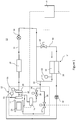
- FIG. 1 shows an example refrigeration apparatus 10 comprising a refrigerant circuit.
- the refrigeration circuit comprises a compressor 12, a condensing device 14, an expansion valve 16 and an evaporator 18, which are fluidically connected to one another in series and in that order by a main refrigerant line 11, where the evaporator is connected to the compressor 12 to form a circuit.
- the compressor 12 in this example is a two-stage compressor comprising a first stage compressor fan 20 and a second stage compressor fan 22.
- the compressor may have only one stage or the compressor may have more than two stages.
- the compressor 12 comprises a motor 24 which is configured to drive the first stage compressor fan 20 and the second stage compressor fan 22.
- the motor 24 is connected to an inverter 26 which is configured to control the speed of the motor 24.
- the condensing device 14 is disposed downstream of the compressor 12, and comprises two stages of condensing. In a first stage, the condensing device 14 comprises a condenser 28, and in a second stage, the condensing device 14 comprises a sub-cooler 30. The sub-cooler 30 is disposed downstream of the condenser 28.
- the expansion valve 16 is disposed downstream of the condensing device 14, and the evaporator 18 is disposed between the expansion valve 16 and the compressor 12.
- check valve 32 Between the compressor 12 and the condensing device 14 is disposed a check valve 32, which is configured to ensure that refrigerant flows from the compressor 12 to the condenser 28, and does not allow refrigerant to flow in an opposing direction from the condenser 28 to the compressor 12.
- a cooling line 34 fluidically connects the sub-cooler 30 directly to the compressor 12 to provide sub-cooled refrigerant to the compressor 12 in order to cool the compressor 12.
- the cooling line 34 taps sub-cooled refrigerant from the main refrigerant line 11 connecting the sub-cooler 30 to the expansion valve 16, and directs the tapped refrigerant to the compressor 12.
- the cooling line 34 is split into a motor cooling line 36 and an inverter cooling line 38.
- the motor cooling line 36 fluidically connects the sub-cooler 30 to the motor 24 so that sub-cooled refrigerant is directed to the motor 24 and permitted to expand to cool the motor 24 by heat transfer.
- the inverter cooling line 38 fluidically connects the sub-cooler 30 to the inverter 26 so that sub-cooled refrigerant is directed to the inverter 26 and permitted to expand to cool the inverter by heat transfer.
- the motor cooling line 36 comprises a motor cooling valve 37 which is configured to control the flow rate of refrigerant through the motor cooling line 36 to the motor 24.
- the inverter cooling line 38 comprises an inverter cooling valve 39 which is configured to control the flow rate of refrigerant through the inverter cooling line 38 to the inverter 26.
- the motor cooling line 36 and the inverter cooling line 38 are further connected to the main refrigerant line 11 at a return point 40 in between the first stage compressor fan 20 and the second stage compressor fan 22, so that the tapped refrigerant in the motor cooling line 36 and the inverter cooling line 38 rejoins the main refrigerant line 11 after being used to cool the motor 24 and the inverter 26 respectively.
- the maximum possible refrigerant flow through the motor cooling line 36 and the inverter cooling line 38 i.e.
- the motor cooling valve 37 and the inverter cooling valve 39 are fully open) is dependent on the pressure of refrigerant in the main refrigerant line 11 at the return point 40, and the pressure of refrigerant in the main refrigerant line 11 at an outlet of the sub-cooler 30.
- the pressure at the return point 40 must be lower than the pressure at the outlet of the sub-cooler 30 by at least a threshold amount in order to passively drive the sub-cooled refrigerant through the motor cooling line 36 and the inverter cooling line 38 to the return point 40 (i.e. there must be a sufficiently high pressure differential to drive the refrigerant through the motor cooling line 36 and the inverter cooling line 38).
- the threshold amount may be an absolute threshold, or may be dependent on the load on the compressor 12.
- the motor cooling line and the inverter cooling line may be connected to the main refrigerant line upstream of the compressor fan (i.e. the return point may be upstream of the compressor fan).
- An outlet of the condenser 28 is also fluidically connected to the main refrigerant line 11 upstream of the expansion valve 16 by a bypass line 42.
- the bypass line 42 is arranged to permit at least some of the refrigerant in the main refrigerant line 11 to bypass the sub-cooler 30, so that some of the refrigerant flows directly from the condenser 28 to the main refrigerant line 11 between the sub-cooler 30 and the expansion valve 16.
- the bypass line 42 comprises a bypass valve 44 which is configured to be selectively opened and closed in order to control flow of the refrigerant through the bypass line 42.
- a controller 50 is connected to the bypass valve 44, the motor cooling valve 37, the inverter cooling valve 39, and the expansion valve 16.
- the controller 50 is configured to selectively open and close the valves to control the flow of refrigerant through the refrigerant circuit.
- the controller 50 or the additional controller may also control the operation of the inverter and the compressor in use.
- the bypass valve 44, motor cooling valve 37, inverter cooling valve 39 and expansion valve 16 in this example are modulating valves, such that the controller 50 may vary the size of an opening of each valve to precisely control the flow rate of refrigerant through them.
- these valves may be binary valves, which can be opened and closed selectively, but with no control of the size of the opening, and thus no direct control of the flow rate through them.
- the valves may be any combination of binary and modulating valves.
- the controller 50 in this example is therefore configured to control the bypass valve 44, the motor cooling valve 37, the inverter cooling valve 39 and the expansion valve 16 to precisely control the flow rate of refrigerant through the bypass line 42, the motor cooling line 36, the inverter cooling line 38 and the main refrigerant line 11 in use.
- the refrigeration apparatus 10 also comprises a first pressure sensor 52 arranged to monitor the pressure of refrigerant in the main refrigerant line 11 at the outlet of the sub-cooler 30.
- the refrigeration apparatus 10 further comprises a second pressure sensor 54 arranged to monitor the pressure in the main refrigerant line 11 upstream (i.e. at the inlet) of the first compressor fan 20, and a third pressure sensor 55 arranged to monitor the pressure downstream (i.e. at the outlet) of the second compressor fan 22.
- the pressure of refrigerant at the return point 40 is calculated by the controller 50 based on the pressures monitored by the second pressure sensor 54 and the third pressure sensor 55.
- the second pressure sensor may be arranged to monitor the pressure in the main refrigerant line upstream of the compressor fan, and there may not be a third pressure sensor.
- the sensors may be any sensor which can output a parameter which is indicative of the pressure of refrigerant, such as a temperature sensor.
- the controller 50 is arranged to monitor a first pressure parameter received from the first pressure sensor 52, relating to the pressure of refrigerant in the main refrigerant line 11 downstream of the sub-cooler 30 or at the cooling line 34.
- the controller is arranged to monitor a second pressure parameter received from the second pressure sensor 54, relating to the pressure of refrigerant in the main refrigerant line 11 at the return point 40.
- the controller 50 is configured to control the bypass valve 44 based on the first pressure parameter and the second pressure parameter. This process will be described in more detail with reference to Figures 2 and 3 below.
- the refrigerant apparatus may further comprise a temperature sensor, which is arranged to monitor the temperature of the refrigerant at the outlet of the condenser, the outlet of the sub-cooler and/or downstream of the expansion device.
- the refrigeration apparatus 10 operates under normal conditions with the bypass valve 44 closed, such that all of the refrigerant is passed through the sub-cooler 30. It compresses vaporised refrigerant in the compressor 12 which pressurises the refrigerant, thereby increasing the temperature of the refrigerant.
- the vaporised refrigerant may enter the compressor at a pressure of approximately 2.7 bar (270 kPa), and a temperature of 6°C, and may leave the compressor at a pressure of approximately 10 bar (1000 kPa), and a temperature of 50°C for an outdoor ambient temperature of 35°C.
- Refrigerant leaves the compressor 12 in a vapour phase.
- the refrigerant passes through the condensing device 14 in which it passes first through the condenser 28 to condense the refrigerant by heat transfer to ambient air.
- the refrigerant is discharged from the outlet of the condenser 28 in liquid form.
- the refrigerant is then passed through the sub-cooler 30 where it is further cooled.
- the refrigerant may enter the condenser at 10 bar (1000 kPa) (the same pressure as the refrigerant leaving the compressor 12), and may lose 0.5 bar (50 kPa) of pressure across the condenser 28.
- the refrigerant may lose a further 1.5 bar (150 kPa) across the sub-cooler 30 such that it leaves the sub-cooler 30 at a pressure of 8 bar (800 kPa) which leaves a pressure differential of 2.8 bar (280 kPa) between the return point 40 and the outlet of the sub-cooler 30, which is sufficient for refrigerant flow through the motor cooling line 36 and the inverter cooling line 38 by opening the respective motor and inverter cooling valves 37 and 39.
- the refrigerant then flows through the expansion valve 16 where it is allowed to expand. This decreases the pressure of the refrigerant, and therefore decreases the temperature further, such that the refrigerant is cooler than the temperature of the water or air to be cooled.
- the pressure of the refrigerant downstream of the expansion valve 16 may be 2.7 bar (270 kPa), and the temperature of the refrigerant downstream of the expansion valve 16 may be 6°C.
- An opening in the expansion valve 16 may be variable such that the pressure drop, and therefore the temperature drop of the refrigerant across the expansion valve can be varied.
- the size of the opening may be controlled to ensure that the temperature of the refrigerant exiting the expansion valve 16, and therefore entering the evaporator 18 is maintained constant, such that the refrigeration capacity of the refrigeration apparatus 10 is maintained constant.
- the refrigerant downstream of the expansion valve 16 is then directed to the evaporator 18 where heat is exchanged between air or water to be cooled and the cooled refrigerant.
- the refrigerant evaporates such that it leaves the evaporator 18 in a vapour phase, and the air is cooled.
- the controller 50 controls the motor cooling valve 37 and the inverter cooling valve 39 to control the flow of sub-cooled refrigerant to the motor 24 and the inverter 26 respectively.
- the flow rate of refrigerant from the sub-cooler 30 to the compressor 12 may be insufficient to cool the motor 24 and the inverter 26, even with the motor cooling valve 37 and the inverter cooling valve 39 fully open.
- the bypass valve 44 may be opened to enable a larger supply of refrigerant to the compressor, as explained below.
- Figures 2 and 3 are flow charts showing a method of operating the example refrigeration apparatus 10 to modulate the amount of refrigerant being delivered to the compressor 12 as required. This may be used when the refrigeration apparatus 10 is experiencing abnormal conditions.
- Such conditions may occur, for example, when the ambient temperature is low, such as 10°C.
- the compressor outlet pressure may be 5.8 bar (580 kPa)
- the pressure of the refrigerant downstream of the expansion valve 16 may be 2.7 bar (270 kPa) and the refrigerant temperature may be 30°C at the inlet to the compressor.
- the low temperature of the ambient air means that there is a large pressure loss across the condenser 28 and the sub-cooler 30, such that the pressure differential between the cooling line 34 and the return point 40 is not large enough to drive enough refrigerant to the motor 24 and the inverter 26, even when the motor cooling valve 37 and the inverter cooling valve 39 are fully open. Therefore, cooling of the motor 24 and the inverter 26 may not be enough, such that these components may overheat, potentially resulting in damage or malfunction.
- the pressure differential between the cooling line 34 and the return point 40 can be increased by opening the bypass valve 44. This allows refrigerant to bypass the sub-cooler 30 so that there is a smaller pressure drop between the outlet of the condenser 28 and the cooling line 34.
- Figure 2 shows a method 200 of operating the refrigeration apparatus 10 to overcome such conditions.
- step 202 the method determines whether there is insufficient refrigerant being delivered from the main refrigerant line downstream of the sub-cooler 30 to the compressor 12 (e.g. insufficient to cool the motor 24 and the inverter 26).
- step 204 the bypass valve 44 is controlled to open to increase the flow rate of refrigerant through the bypass valve 44.
- Increasing the flow of refrigerant through the bypass valve 44 decreases the flow of refrigerant through the sub-cooler 30, such that the pressure of the refrigerant in the main refrigerant line 11 between the sub-cooler 30 and the expansion valve 16 increases. This is because less of the refrigerant is experiencing a pressure loss across the sub-cooler 30.
- Increasing the pressure of the refrigerant in the main refrigerant line 11 at the cooling line 34 means that the pressure differential between the cooling line 34 and the return point 40 increases, so that more refrigerant is driven through the motor cooling line 36 and the inverter cooling line 38.
- bypass valve 44 is a modulating valve and in step 204 the bypass valve 44 is incrementally opened, and the method returns to step 202 to determine whether there is still insufficient refrigerant being delivered to the compressor 12. This generates a negative feedback loop.
- the bypass valve may be controlled to open by a specific amount dependent on the degree of insufficient supply of refrigerant to the compressor 12.
- the method determines whether there is too much refrigerant being delivered to the compressor in step 206. If there is not too much refrigerant being delivered, and the refrigerant delivered is not insufficient, then the level of refrigerant being delivered is at a desired set-point. The method then proceeds to step 208 in which no changes are made to the bypass valve 44, and the method returns to step 202.
- step 210 to decrease the flow rate of refrigerant through the bypass valve 44 (e.g. by reducing the size of an opening in the bypass valve 44, or by closing the bypass valve 44). If the bypass valve 44 is already closed, the refrigeration apparatus 10 can return to normal operation, in which the bypass valve 44 is closed. The method then returns to step 202.
- Figure 3 shows an example method, in detail, of determining whether there is insufficient, too much or just enough refrigerant being delivered to the compressor 12. This is determined by monitoring the pressure differential from the cooling line 34 to the return point 40.
- the pressure differential will ideally fall within a set-range or at a set-point, where it will be determined that there is just enough refrigerant being delivered to the compressor 12.
- the set-range may be an absolute range of acceptable pressure differentials, or it may vary and be calculated based on the loading on the compressor 12.
- the controller 50 is configured to maintain the pressure differential within a set-range which is defined between a lower threshold and an upper threshold.
- the controller 50 may determine the thresholds in real time by monitoring the compressor loading and looking up a corresponding thresholds from a look-up table.
- the thresholds may be calculated using a formula based on the compressor loading. For example the minimum threshold pressure at 30% compressor loading may be 0.2 bar (20kPa) while at 100% compressor load it could be as much as 1 bar (100kPa) times more.
- step 220 the method includes monitoring a first pressure parameter relating to the pressure of refrigerant in the main refrigerant line 11 at the outlet of the sub-cooler 30. This may be monitored with the first pressure sensor 52.
- the method includes monitoring a second pressure parameter relating to the pressure of refrigerant in the main refrigerant line 11 at the return point 40 (i.e. between the first stage compressor fan 20 and the second stage compressor fan 22). This may be monitored with the second pressure sensor 54.
- the second pressure parameter may relate to the pressure of refrigerant in the main refrigerant line upstream of the compressor fan.
- the method determines whether there is insufficient, just enough, or too much refrigerant being delivered to the compressor 12 in steps 224-234, based on the first pressure parameter and the second pressure parameter.
- the method includes calculating a difference parameter relating to the difference between the first pressure parameter and the second pressure parameter. This will indicate the pressure differential of refrigerant between the outlet of the sub-cooler 30 (i.e. the cooling line 34) and the return point 40 of the compressor.
- step 226 the difference parameter is compared to the lower threshold, and it is determined whether the difference parameter is below the lower threshold. If the difference parameter is below the lower threshold, then it is determined in step 228 that the pressure differential between the sub-cooler 30 and the return point 40 is not high enough, such that there is insufficient refrigerant being delivered to the compressor 12 to cool it. If the difference parameter is not below the lower threshold (i.e. it is above the lower threshold), the method proceeds to step 230.
- step 230 the difference parameter is compared to the second, upper threshold, and it is determined whether the difference parameter is above the upper threshold. If the difference parameter is above the upper threshold, it is determined in step 232 that there is too much refrigerant being delivered to the compressor 12. If the difference parameter is below or equal to the upper threshold, the difference parameter must be within the set-range, such that it is determined in step 234 that there is just enough refrigerant being delivered to the compressor 12.
- the upper threshold and the lower threshold may be the same, such that it is only determined that there is enough refrigerant being delivered to the compressor when the difference parameter is equal to the threshold or set-point.
- the difference parameter is above the threshold, it is determined that there is too much refrigerant being delivered to the compressor, and if the difference parameter is below the threshold, it is determined that there is not enough refrigerant being delivered to the compressor.
- the controller 50 implementing the method controls the bypass valve 44 to incrementally increase or decrease a flow rate through the bypass valve 44, in a negative feedback loop so that the cooling of the compressor 12 is maintained at the desired point.
- determining whether there is insufficient or too much refrigerant delivered to the compressor is based on the monitored pressure at the outlet of the sub-cooler 30 and the return point 40, this could be determined by other means, such as by monitoring the flow rate of fluid through the cooling line, the motor cooling line and/or the inverter cooling line, or by monitoring the temperature of the motor 24 and the inverter 26 to infer that there is insufficient refrigerant if the motor temperature is raised above a threshold.
Landscapes
- Engineering & Computer Science (AREA)
- Physics & Mathematics (AREA)
- Mechanical Engineering (AREA)
- Thermal Sciences (AREA)
- General Engineering & Computer Science (AREA)
- Air Conditioning Control Device (AREA)
- Devices That Are Associated With Refrigeration Equipment (AREA)
Abstract
Description
- The present invention relates to a refrigerant apparatus and a method of operating a refrigeration apparatus.
- Refrigeration units typically comprise a compressor, a condenser, an expansion valve and an evaporator connected in series through which refrigerant flows. Ambient air flows over the condenser to cool pressurised refrigerant in the condenser, and air or water to be cooled flows over the evaporator to transfer heat to the refrigerant in the evaporator, to thereby cool the air.
- Components of the compressor get hot during use, and requiring cooling. Refrigerant from the condenser may be passively driven to the compressor and used to cool the components of the compressor. However, it is possible under certain conditions for the amount of refrigerant directed to the compressor to be insufficient to cool the components of the compressor. Previously considered methods of operating a refrigeration unit have relied on moving away from the most efficient operation in order to overcome this problem.
- According to a first aspect, there is provided a refrigeration apparatus comprising a refrigerant circuit, the refrigerant circuit comprising: a compressor comprising a compressor fan and a motor to drive the compressor fan; a condensing device disposed downstream of the compressor, the condensing device comprising a condenser and a sub-cooler; an expansion valve disposed downstream of the condensing device; an evaporator disposed between the expansion valve and the compressor; a main refrigerant line fluidically connecting, in a loop in series: the compressor, condensing device, expansion valve and evaporator; and a motor cooling line comprising a motor cooling valve, the motor cooling line fluidically connecting the sub-cooler to the motor to tap refrigerant from the main refrigerant line to cool the motor, wherein the motor cooling line is further connected to the main refrigerant line at a return point which is upstream of the compressor fan to return refrigerant to the main refrigerant line at the compressor fan; wherein the refrigerant circuit further comprises a bypass line fluidically connecting an outlet of the condenser to the expansion valve to bypass the sub-cooler, wherein the bypass line comprises a bypass valve to selectively permit refrigerant in the main refrigerant line to bypass the sub-cooler.
- The compressor may comprise an inverter. The sub-cooler may be connected to the inverter by an inverter cooling line comprising an inverter cooling valve, and wherein the inverter cooling line may be further connected to the main refrigerant line at the return point to direct refrigerant from the inverter to the main refrigerant line at the compressor fan.
- The refrigeration apparatus may comprise a controller. The controller may be configured to control opening and closing of the bypass valve. The controller may be configured to control opening and closing of the inverter cooling valve. The controller may be configured to control opening and closing of the motor cooling valve. There may be an additional controller which is integral with the compressor, and which is configured to control the operation of the motor and the inverter, and to control opening and closing of the motor cooling valve, the inverter cooling valve, and/or the expansion valve.
- The bypass valve may be a modulating valve. The controller may be configured to control the bypass valve to control the flow rate of refrigerant through the bypass valve.
- The refrigeration apparatus may comprise a first pressure sensor arranged to monitor the pressure of refrigerant exiting the sub-cooler, and a second pressure sensor arranged to monitor the pressure in the main refrigerant line at the return point; wherein the controller is arranged to receive a first pressure parameter from the first pressure sensor, and a second pressure parameter from the second pressure sensor, and to control the bypass valve based on the first pressure parameter and the second pressure parameter.
- The refrigerant apparatus may comprise a first pressure sensor arranged to monitor the pressure of refrigerant exiting the sub-cooler, a second pressure sensor arranged to monitor the pressure in the main refrigerant line an inlet of the compressor, and a third pressure sensor arranged to monitor the pressure in the main refrigerant line at an outlet of the compressor. The controller may be arranged to receive a first pressure parameter from the first pressure sensor, a second pressure parameter from the second pressure sensor, and a third pressure parameter from the third pressure sensor. The controller may be arranged to control the bypass valve based on the first pressure parameter, the second pressure parameter, and the third pressure parameter.
- The compressor may be a two-stage compressor comprising a first stage compressor fan and a second stage compressor fan, and wherein the return point is between a first stage compressor fan and the second stage compressor fan.
- According to a second aspect, there is provided a method of operating a refrigeration apparatus according to any preceding claim, the method comprising: determining whether insufficient refrigerant is being delivered from the sub-cooler to the compressor; and in response to determining that insufficient refrigerant is being delivered from the sub-cooler to the compressor, controlling the bypass valve to increase the flow rate of refrigerant through the bypass valve.
- Increasing the flow of refrigerant through the bypass valve may include opening the bypass valve or incrementally increasing the size of an opening through the bypass valve.
- Determining whether insufficient refrigerant is being delivered to the compressor may include: monitoring a first pressure parameter relating to the pressure of refrigerant in the main refrigerant line at an outlet of the sub-cooler; monitoring a second pressure parameter relating to the pressure in the main refrigerant line at a return point upstream of a compressor fan; and determining whether there is insufficient cooling fluid being delivered to the compressor based on the first pressure parameter and the second pressure parameter.
- The second pressure parameter may relate to the pressure in the main refrigerant line at a return point between a first stage compressor fan and a second stage compressor fan of a two-stage compressor.
- Determining whether there is insufficient refrigerant being delivered to the compressor may include: calculating a difference parameter relating to a difference between the first pressure parameter and the second pressure parameter; comparing the difference parameter to a first threshold; and if the difference parameter is below the first threshold, determining that there is insufficient refrigerant being delivered to the compressor.
- The method may further comprise determining whether there is too much refrigerant being delivered to the compressor. The method may comprise reducing the flow of refrigerant through the bypass valve in response to determining that there is too much refrigerant being delivered to the compressor.
- Reducing the flow of refrigerant through the bypass valve may include closing the bypass valve or incrementally decreasing the size of an opening through the bypass valve.
- Determining whether there is too much refrigerant being delivered to the compressor may comprise: comparing the difference parameter to a second threshold; and if the difference parameter is above the second threshold, determining that there is too much refrigerant being delivered to the compressor.
- The first threshold and the second threshold may be the same.
- The skilled person will appreciate that except where mutually exclusive, a feature or parameter described in relation to any one of the above aspects may be applied to any other aspect. Furthermore, except where mutually exclusive, any feature or parameter described herein may be applied to any aspect and/or combined with any other feature or parameter described herein.
- Embodiments will now be described, by way of example only, with reference to the accompanying Figures, in which:
-
Figure 1 shows a schematic representation of an example refrigeration apparatus; and -
Figures 2 and3 are flow charts showing steps of an example method of operating a refrigeration apparatus. -
Figure 1 shows anexample refrigeration apparatus 10 comprising a refrigerant circuit. The refrigeration circuit comprises acompressor 12, acondensing device 14, anexpansion valve 16 and anevaporator 18, which are fluidically connected to one another in series and in that order by amain refrigerant line 11, where the evaporator is connected to thecompressor 12 to form a circuit. - The
compressor 12 in this example is a two-stage compressor comprising a firststage compressor fan 20 and a secondstage compressor fan 22. In other examples, the compressor may have only one stage or the compressor may have more than two stages. - The
compressor 12 comprises amotor 24 which is configured to drive the firststage compressor fan 20 and the secondstage compressor fan 22. Themotor 24 is connected to aninverter 26 which is configured to control the speed of themotor 24. - The
condensing device 14 is disposed downstream of thecompressor 12, and comprises two stages of condensing. In a first stage, thecondensing device 14 comprises acondenser 28, and in a second stage, thecondensing device 14 comprises asub-cooler 30. Thesub-cooler 30 is disposed downstream of thecondenser 28. - The
expansion valve 16 is disposed downstream of thecondensing device 14, and theevaporator 18 is disposed between theexpansion valve 16 and thecompressor 12. - Between the
compressor 12 and thecondensing device 14 is disposed acheck valve 32, which is configured to ensure that refrigerant flows from thecompressor 12 to thecondenser 28, and does not allow refrigerant to flow in an opposing direction from thecondenser 28 to thecompressor 12. - A
cooling line 34 fluidically connects thesub-cooler 30 directly to thecompressor 12 to provide sub-cooled refrigerant to thecompressor 12 in order to cool thecompressor 12. In this example, thecooling line 34 taps sub-cooled refrigerant from themain refrigerant line 11 connecting thesub-cooler 30 to theexpansion valve 16, and directs the tapped refrigerant to thecompressor 12. - Within the
compressor 12, thecooling line 34 is split into amotor cooling line 36 and an inverter cooling line 38. Themotor cooling line 36 fluidically connects thesub-cooler 30 to themotor 24 so that sub-cooled refrigerant is directed to themotor 24 and permitted to expand to cool themotor 24 by heat transfer. The inverter cooling line 38 fluidically connects thesub-cooler 30 to theinverter 26 so that sub-cooled refrigerant is directed to theinverter 26 and permitted to expand to cool the inverter by heat transfer. - The
motor cooling line 36 comprises amotor cooling valve 37 which is configured to control the flow rate of refrigerant through themotor cooling line 36 to themotor 24. The inverter cooling line 38 comprises aninverter cooling valve 39 which is configured to control the flow rate of refrigerant through the inverter cooling line 38 to theinverter 26. - The
motor cooling line 36 and the inverter cooling line 38 are further connected to themain refrigerant line 11 at areturn point 40 in between the firststage compressor fan 20 and the secondstage compressor fan 22, so that the tapped refrigerant in themotor cooling line 36 and the inverter cooling line 38 rejoins themain refrigerant line 11 after being used to cool themotor 24 and theinverter 26 respectively. The maximum possible refrigerant flow through themotor cooling line 36 and the inverter cooling line 38 (i.e. if themotor cooling valve 37 and theinverter cooling valve 39 are fully open) is dependent on the pressure of refrigerant in themain refrigerant line 11 at thereturn point 40, and the pressure of refrigerant in themain refrigerant line 11 at an outlet of thesub-cooler 30. The pressure at thereturn point 40 must be lower than the pressure at the outlet of thesub-cooler 30 by at least a threshold amount in order to passively drive the sub-cooled refrigerant through themotor cooling line 36 and the inverter cooling line 38 to the return point 40 (i.e. there must be a sufficiently high pressure differential to drive the refrigerant through themotor cooling line 36 and the inverter cooling line 38). - The threshold amount may be an absolute threshold, or may be dependent on the load on the
compressor 12. - In an example in which the compressor is a single stage compressor comprising one compressor fan, the motor cooling line and the inverter cooling line may be connected to the main refrigerant line upstream of the compressor fan (i.e. the return point may be upstream of the compressor fan).
- An outlet of the
condenser 28 is also fluidically connected to the mainrefrigerant line 11 upstream of theexpansion valve 16 by abypass line 42. Thebypass line 42 is arranged to permit at least some of the refrigerant in the mainrefrigerant line 11 to bypass the sub-cooler 30, so that some of the refrigerant flows directly from thecondenser 28 to the mainrefrigerant line 11 between the sub-cooler 30 and theexpansion valve 16. - The
bypass line 42 comprises abypass valve 44 which is configured to be selectively opened and closed in order to control flow of the refrigerant through thebypass line 42. - A
controller 50 is connected to thebypass valve 44, themotor cooling valve 37, theinverter cooling valve 39, and theexpansion valve 16. Thecontroller 50 is configured to selectively open and close the valves to control the flow of refrigerant through the refrigerant circuit. In some examples, there may be an additional controller which is integral with the compressor, and which is configured to control the motor cooling valve, and the inverter cooling valve. Thecontroller 50 or the additional controller may also control the operation of the inverter and the compressor in use. - The
bypass valve 44,motor cooling valve 37,inverter cooling valve 39 andexpansion valve 16 in this example are modulating valves, such that thecontroller 50 may vary the size of an opening of each valve to precisely control the flow rate of refrigerant through them. In other examples, these valves may be binary valves, which can be opened and closed selectively, but with no control of the size of the opening, and thus no direct control of the flow rate through them. In some examples, the valves may be any combination of binary and modulating valves. - The
controller 50 in this example is therefore configured to control thebypass valve 44, themotor cooling valve 37, theinverter cooling valve 39 and theexpansion valve 16 to precisely control the flow rate of refrigerant through thebypass line 42, themotor cooling line 36, the inverter cooling line 38 and the mainrefrigerant line 11 in use. - In this example, the
refrigeration apparatus 10 also comprises afirst pressure sensor 52 arranged to monitor the pressure of refrigerant in the mainrefrigerant line 11 at the outlet of the sub-cooler 30. Therefrigeration apparatus 10 further comprises asecond pressure sensor 54 arranged to monitor the pressure in the mainrefrigerant line 11 upstream (i.e. at the inlet) of thefirst compressor fan 20, and athird pressure sensor 55 arranged to monitor the pressure downstream (i.e. at the outlet) of thesecond compressor fan 22. The pressure of refrigerant at thereturn point 40 is calculated by thecontroller 50 based on the pressures monitored by thesecond pressure sensor 54 and thethird pressure sensor 55. The pressure of refrigerant at the return point 40 (pr) is calculated as the square root of the pressure of refrigerant at the inlet of the first compressor fan 20 (pi) times the pressure of refrigerant at the outlet of the second compressor fan (p2) (i.e.
- In an example in which the compressor is a single stage compressor having one compressor fan, the second pressure sensor may be arranged to monitor the pressure in the main refrigerant line upstream of the compressor fan, and there may not be a third pressure sensor. In other examples, the sensors may be any sensor which can output a parameter which is indicative of the pressure of refrigerant, such as a temperature sensor. In yet other examples, there may be a pressure sensor arranged to monitor the pressure at the
return point 40 directly. - The
controller 50 is arranged to monitor a first pressure parameter received from thefirst pressure sensor 52, relating to the pressure of refrigerant in the mainrefrigerant line 11 downstream of the sub-cooler 30 or at the coolingline 34. The controller is arranged to monitor a second pressure parameter received from thesecond pressure sensor 54, relating to the pressure of refrigerant in the mainrefrigerant line 11 at thereturn point 40. Thecontroller 50 is configured to control thebypass valve 44 based on the first pressure parameter and the second pressure parameter. This process will be described in more detail with reference toFigures 2 and3 below. - The refrigerant apparatus may further comprise a temperature sensor, which is arranged to monitor the temperature of the refrigerant at the outlet of the condenser, the outlet of the sub-cooler and/or downstream of the expansion device.
- The
refrigeration apparatus 10 operates under normal conditions with thebypass valve 44 closed, such that all of the refrigerant is passed through the sub-cooler 30. It compresses vaporised refrigerant in thecompressor 12 which pressurises the refrigerant, thereby increasing the temperature of the refrigerant. For example, the vaporised refrigerant may enter the compressor at a pressure of approximately 2.7 bar (270 kPa), and a temperature of 6°C, and may leave the compressor at a pressure of approximately 10 bar (1000 kPa), and a temperature of 50°C for an outdoor ambient temperature of 35°C. The pressure at thereturn point 40 is therefore calculated to be:
compressor 12 in a vapour phase. - The refrigerant passes through the condensing
device 14 in which it passes first through thecondenser 28 to condense the refrigerant by heat transfer to ambient air. The refrigerant is discharged from the outlet of thecondenser 28 in liquid form. The refrigerant is then passed through the sub-cooler 30 where it is further cooled. There is a pressure loss in the refrigerant across thecondenser 28 and the sub-cooler 30 due to large mass flow in small channels. For example, the refrigerant may enter the condenser at 10 bar (1000 kPa) (the same pressure as the refrigerant leaving the compressor 12), and may lose 0.5 bar (50 kPa) of pressure across thecondenser 28. The refrigerant may lose a further 1.5 bar (150 kPa) across the sub-cooler 30 such that it leaves the sub-cooler 30 at a pressure of 8 bar (800 kPa) which leaves a pressure differential of 2.8 bar (280 kPa) between thereturn point 40 and the outlet of the sub-cooler 30, which is sufficient for refrigerant flow through themotor cooling line 36 and the inverter cooling line 38 by opening the respective motor andinverter cooling valves - The refrigerant then flows through the
expansion valve 16 where it is allowed to expand. This decreases the pressure of the refrigerant, and therefore decreases the temperature further, such that the refrigerant is cooler than the temperature of the water or air to be cooled. For example, the pressure of the refrigerant downstream of theexpansion valve 16 may be 2.7 bar (270 kPa), and the temperature of the refrigerant downstream of theexpansion valve 16 may be 6°C. - An opening in the
expansion valve 16 may be variable such that the pressure drop, and therefore the temperature drop of the refrigerant across the expansion valve can be varied. The size of the opening may be controlled to ensure that the temperature of the refrigerant exiting theexpansion valve 16, and therefore entering theevaporator 18 is maintained constant, such that the refrigeration capacity of therefrigeration apparatus 10 is maintained constant. - The refrigerant downstream of the
expansion valve 16 is then directed to theevaporator 18 where heat is exchanged between air or water to be cooled and the cooled refrigerant. The refrigerant evaporates such that it leaves theevaporator 18 in a vapour phase, and the air is cooled. - During use, the
motor 24 and theinverter 26 are heated, and must be cooled. Thecontroller 50 controls themotor cooling valve 37 and theinverter cooling valve 39 to control the flow of sub-cooled refrigerant to themotor 24 and theinverter 26 respectively. - Under operating conditions in which the ambient temperature is low (such as 0°C), the flow rate of refrigerant from the sub-cooler 30 to the
compressor 12 may be insufficient to cool themotor 24 and theinverter 26, even with themotor cooling valve 37 and theinverter cooling valve 39 fully open. Under such operating conditions, thebypass valve 44 may be opened to enable a larger supply of refrigerant to the compressor, as explained below. -
Figures 2 and3 are flow charts showing a method of operating theexample refrigeration apparatus 10 to modulate the amount of refrigerant being delivered to thecompressor 12 as required. This may be used when therefrigeration apparatus 10 is experiencing abnormal conditions. - Such conditions may occur, for example, when the ambient temperature is low, such as 10°C. The compressor outlet pressure may be 5.8 bar (580 kPa), the pressure of the refrigerant downstream of the
expansion valve 16 may be 2.7 bar (270 kPa) and the refrigerant temperature may be 30°C at the inlet to the compressor. The pressure at thereturn point 40 would therefore be
condenser 28 andsub-cooler 30 of total of 2 bar (200kPa) the pressure at the outlet of the sub-cooler 30 would be: 5.8 bar - 2 bar = 3.8 bar (380kPa) such that the differential pressure between thereturn point 40 and the outlet of the sub-cooler 30 will be -0.2 bar (-20kPa). In this case there will be no refrigerant transfer to themotor 24 andinverter 26 for cooling, even if themotor cooling valve 37 and theinverter cooling valve 39 are fully open. Under such circumstances, the low temperature of the ambient air means that there is a large pressure loss across thecondenser 28 and the sub-cooler 30, such that the pressure differential between the coolingline 34 and thereturn point 40 is not large enough to drive enough refrigerant to themotor 24 and theinverter 26, even when themotor cooling valve 37 and theinverter cooling valve 39 are fully open. Therefore, cooling of themotor 24 and theinverter 26 may not be enough, such that these components may overheat, potentially resulting in damage or malfunction. As explained above, the pressure differential between the coolingline 34 and thereturn point 40 can be increased by opening thebypass valve 44. This allows refrigerant to bypass the sub-cooler 30 so that there is a smaller pressure drop between the outlet of thecondenser 28 and the coolingline 34. -
Figure 2 shows a method 200 of operating therefrigeration apparatus 10 to overcome such conditions. - In
step 202, the method determines whether there is insufficient refrigerant being delivered from the main refrigerant line downstream of the sub-cooler 30 to the compressor 12 (e.g. insufficient to cool themotor 24 and the inverter 26). - If it is determined that there is insufficient refrigerant being delivered to the
compressor 12, the method proceeds to step 204 in which thebypass valve 44 is controlled to open to increase the flow rate of refrigerant through thebypass valve 44. Increasing the flow of refrigerant through thebypass valve 44 decreases the flow of refrigerant through the sub-cooler 30, such that the pressure of the refrigerant in the mainrefrigerant line 11 between the sub-cooler 30 and theexpansion valve 16 increases. This is because less of the refrigerant is experiencing a pressure loss across the sub-cooler 30. - Increasing the pressure of the refrigerant in the main
refrigerant line 11 at the coolingline 34 means that the pressure differential between the coolingline 34 and thereturn point 40 increases, so that more refrigerant is driven through themotor cooling line 36 and the inverter cooling line 38. - In this example, the
bypass valve 44 is a modulating valve and instep 204 thebypass valve 44 is incrementally opened, and the method returns to step 202 to determine whether there is still insufficient refrigerant being delivered to thecompressor 12. This generates a negative feedback loop. In other examples, the bypass valve may be controlled to open by a specific amount dependent on the degree of insufficient supply of refrigerant to thecompressor 12. - If there is sufficient refrigerant being supplied to the
compressor 12, then the method determines whether there is too much refrigerant being delivered to the compressor instep 206. If there is not too much refrigerant being delivered, and the refrigerant delivered is not insufficient, then the level of refrigerant being delivered is at a desired set-point. The method then proceeds to step 208 in which no changes are made to thebypass valve 44, and the method returns to step 202. - If it is determined that there is too much refrigerant being delivered to the
compressor 12, the method proceeds to step 210 to decrease the flow rate of refrigerant through the bypass valve 44 (e.g. by reducing the size of an opening in thebypass valve 44, or by closing the bypass valve 44). If thebypass valve 44 is already closed, therefrigeration apparatus 10 can return to normal operation, in which thebypass valve 44 is closed. The method then returns to step 202. -
Figure 3 shows an example method, in detail, of determining whether there is insufficient, too much or just enough refrigerant being delivered to thecompressor 12. This is determined by monitoring the pressure differential from the coolingline 34 to thereturn point 40. The pressure differential will ideally fall within a set-range or at a set-point, where it will be determined that there is just enough refrigerant being delivered to thecompressor 12. The set-range may be an absolute range of acceptable pressure differentials, or it may vary and be calculated based on the loading on thecompressor 12. - In the method described below, the
controller 50 is configured to maintain the pressure differential within a set-range which is defined between a lower threshold and an upper threshold. - In an example in which the threshold is dependent on the load on the
compressor 12, thecontroller 50 may determine the thresholds in real time by monitoring the compressor loading and looking up a corresponding thresholds from a look-up table. In other examples, the thresholds may be calculated using a formula based on the compressor loading. For example the minimum threshold pressure at 30% compressor loading may be 0.2 bar (20kPa) while at 100% compressor load it could be as much as 1 bar (100kPa) times more. - In
step 220, the method includes monitoring a first pressure parameter relating to the pressure of refrigerant in the mainrefrigerant line 11 at the outlet of the sub-cooler 30. This may be monitored with thefirst pressure sensor 52. - In
step 222, the method includes monitoring a second pressure parameter relating to the pressure of refrigerant in the mainrefrigerant line 11 at the return point 40 (i.e. between the firststage compressor fan 20 and the second stage compressor fan 22). This may be monitored with thesecond pressure sensor 54. In an example where the compressor is a single stage compressor having only one compressor fan, the second pressure parameter may relate to the pressure of refrigerant in the main refrigerant line upstream of the compressor fan. - The method determines whether there is insufficient, just enough, or too much refrigerant being delivered to the
compressor 12 in steps 224-234, based on the first pressure parameter and the second pressure parameter. - In
step 224, the method includes calculating a difference parameter relating to the difference between the first pressure parameter and the second pressure parameter. This will indicate the pressure differential of refrigerant between the outlet of the sub-cooler 30 (i.e. the cooling line 34) and thereturn point 40 of the compressor. - In
step 226, the difference parameter is compared to the lower threshold, and it is determined whether the difference parameter is below the lower threshold. If the difference parameter is below the lower threshold, then it is determined instep 228 that the pressure differential between the sub-cooler 30 and thereturn point 40 is not high enough, such that there is insufficient refrigerant being delivered to thecompressor 12 to cool it. If the difference parameter is not below the lower threshold (i.e. it is above the lower threshold), the method proceeds to step 230. - In
step 230, the difference parameter is compared to the second, upper threshold, and it is determined whether the difference parameter is above the upper threshold. If the difference parameter is above the upper threshold, it is determined instep 232 that there is too much refrigerant being delivered to thecompressor 12. If the difference parameter is below or equal to the upper threshold, the difference parameter must be within the set-range, such that it is determined instep 234 that there is just enough refrigerant being delivered to thecompressor 12. - In an example in which the ideal pressure differential is a set-point rather than a set-range, the upper threshold and the lower threshold may be the same, such that it is only determined that there is enough refrigerant being delivered to the compressor when the difference parameter is equal to the threshold or set-point. In such an example, if the difference parameter is above the threshold, it is determined that there is too much refrigerant being delivered to the compressor, and if the difference parameter is below the threshold, it is determined that there is not enough refrigerant being delivered to the compressor.
- In this example, the
controller 50 implementing the method controls thebypass valve 44 to incrementally increase or decrease a flow rate through thebypass valve 44, in a negative feedback loop so that the cooling of thecompressor 12 is maintained at the desired point. - Although it has been described that determining whether there is insufficient or too much refrigerant delivered to the compressor is based on the monitored pressure at the outlet of the sub-cooler 30 and the
return point 40, this could be determined by other means, such as by monitoring the flow rate of fluid through the cooling line, the motor cooling line and/or the inverter cooling line, or by monitoring the temperature of themotor 24 and theinverter 26 to infer that there is insufficient refrigerant if the motor temperature is raised above a threshold. - It will be understood that the invention is not limited to the embodiments above-described and various modifications and improvements can be made without departing from the concepts described herein. Except where mutually exclusive, any of the features may be employed separately or in combination with any other features and the disclosure extends to and includes all combinations and sub-combinations of one or more features described herein.
Claims (15)
- A refrigeration apparatus comprising a refrigerant circuit, the refrigerant circuit comprising:a compressor comprising a compressor fan and a motor to drive the compressor fan;a condensing device disposed downstream of the compressor, the condensing device comprising a condenser and a sub-cooler;an expansion valve disposed downstream of the condensing device;an evaporator disposed between the expansion valve and the compressor;a main refrigerant line fluidically connecting, in a loop in series: the compressor, condensing device, expansion valve and evaporator; anda motor cooling line comprising a motor cooling valve, the motor cooling line fluidically connecting the sub-cooler to the motor to tap refrigerant from the main refrigerant line to cool the motor, wherein the motor cooling line is further connected to the main refrigerant line at a return point which is upstream of the compressor fan to return refrigerant to the main refrigerant line at the compressor fan;wherein the refrigerant circuit further comprises a bypass line fluidically connecting an outlet of the condenser to the expansion valve to bypass the sub-cooler, wherein the bypass line comprises a bypass valve to selectively permit refrigerant in the main refrigerant line to bypass the sub-cooler.
- A refrigeration apparatus according to any preceding claim, wherein the compressor comprises an inverter, and wherein the sub-cooler is connected to the inverter by an inverter cooling line comprising an inverter cooling valve, and wherein the inverter cooling line is further connected to the main refrigerant line at the return point to direct refrigerant from the inverter to the main refrigerant line at the compressor fan.
- A refrigeration apparatus according to claim 1 or 2, comprising a controller configured to control opening and closing of the bypass valve.
- A refrigeration apparatus according to claim 2 and 3 wherein the controller is configured to control opening and closing of the inverter cooling valve.
- A refrigeration apparatus according to claim 3 or 4, wherein the bypass valve is a modulating valve, and wherein the controller is configured to control the bypass valve to control the flow rate of refrigerant through the bypass valve.
- A refrigeration apparatus according to any of claims 3-5, comprising a first pressure sensor arranged to monitor the pressure of refrigerant exiting the sub-cooler, and a second pressure sensor arranged to monitor the pressure in the main refrigerant line at the return point;
wherein the controller is arranged to receive a first pressure parameter from the first pressure sensor, and a second pressure parameter from the second pressure sensor, and to control the bypass valve based on the first pressure parameter and the second pressure parameter. - A refrigeration apparatus according to claims 3-5, comprising a first pressure sensor arranged to monitor the pressure of refrigerant exiting the sub-cooler, a second pressure sensor arranged to monitor the pressure in the main refrigerant line an inlet of the compressor, and a third pressure sensor arranged to monitor the pressure in the main refrigerant line at an outlet of the compressor;
wherein the controller is arranged to receive a first pressure parameter from the first pressure sensor, a second pressure parameter from the second pressure sensor, and a third pressure parameter from the third pressure sensor, and wherein the controller is arranged to control the bypass valve based on the first pressure parameter, the second pressure parameter, and the third pressure parameter. - A refrigeration apparatus according to any preceding claim, wherein the compressor is a two-stage compressor comprising a first stage compressor fan and a second stage compressor fan, and wherein the return point is between a first stage compressor fan and the second stage compressor fan.
- A refrigeration apparatus according to any of claims 3-8, wherein the controller is configured to control opening and closing of the motor cooling valve.
- A method of operating a refrigeration apparatus according to any preceding claim, the method comprising:determining whether insufficient refrigerant is being delivered from the sub-cooler to the compressor; andin response to determining that insufficient refrigerant is being delivered from the sub-cooler to the compressor, controlling the bypass valve to increase the flow rate of refrigerant through the bypass valve.
- A method according to claim 10, wherein determining whether insufficient refrigerant is being delivered to the compressor includes:monitoring a first pressure parameter relating to the pressure of refrigerant in the main refrigerant line at an outlet of the sub-cooler;monitoring a second pressure parameter relating to the pressure in the main refrigerant line at a return point upstream of a compressor fan; anddetermining whether there is insufficient cooling fluid being delivered to the compressor based on the first pressure parameter and the second pressure parameter.
- A method according to claim 11, wherein the second pressure parameter relates to the pressure in the main refrigerant line at a return point between a first stage compressor fan and a second stage compressor fan of a two-stage compressor.
- A method according to claim 11 or 12, wherein determining whether there is insufficient refrigerant being delivered to the compressor includes:calculating a difference parameter relating to a difference between the first pressure parameter and the second pressure parameter;comparing the difference parameter to a first threshold; andif the difference parameter is below the first threshold, determining that there is insufficient refrigerant being delivered to the compressor.
- A method according to any of claims 10-13, wherein the method further comprises determining whether there is too much refrigerant being delivered to the compressor, and in response to determining that there is too much refrigerant being delivered to the compressor, reducing the flow of refrigerant through the bypass valve.
- A method according to claim 14, wherein determining whether there is too much refrigerant being delivered to the compressor comprises:comparing the difference parameter to a second threshold; andif the difference parameter is above the second threshold, determining that there is too much refrigerant being delivered to the compressor.
Priority Applications (4)
| Application Number | Priority Date | Filing Date | Title |
|---|---|---|---|
| DK20162093.7T DK3879207T3 (en) | 2020-03-10 | 2020-03-10 | REFRIGERATING APPARATUS AND METHOD OF OPERATING THEREOF |
| EP20162093.7A EP3879207B1 (en) | 2020-03-10 | 2020-03-10 | Refrigeration apparatuses and operating method thereof |
| US17/166,395 US20210285704A1 (en) | 2020-03-10 | 2021-02-03 | Refrigeration apparatus |
| CN202110250583.3A CN113375351A (en) | 2020-03-10 | 2021-03-08 | Refrigeration device |
Applications Claiming Priority (1)
| Application Number | Priority Date | Filing Date | Title |
|---|---|---|---|
| EP20162093.7A EP3879207B1 (en) | 2020-03-10 | 2020-03-10 | Refrigeration apparatuses and operating method thereof |
Publications (2)
| Publication Number | Publication Date |
|---|---|
| EP3879207A1 true EP3879207A1 (en) | 2021-09-15 |
| EP3879207B1 EP3879207B1 (en) | 2023-09-06 |
Family
ID=69804473
Family Applications (1)
| Application Number | Title | Priority Date | Filing Date |
|---|---|---|---|
| EP20162093.7A Active EP3879207B1 (en) | 2020-03-10 | 2020-03-10 | Refrigeration apparatuses and operating method thereof |
Country Status (4)
| Country | Link |
|---|---|
| US (1) | US20210285704A1 (en) |
| EP (1) | EP3879207B1 (en) |
| CN (1) | CN113375351A (en) |
| DK (1) | DK3879207T3 (en) |
Families Citing this family (1)
| Publication number | Priority date | Publication date | Assignee | Title |
|---|---|---|---|---|
| US12188701B2 (en) * | 2022-09-09 | 2025-01-07 | Copeland Lp | Systems and methods for providing compressor cooling |
Citations (4)
| Publication number | Priority date | Publication date | Assignee | Title |
|---|---|---|---|---|
| US3859815A (en) * | 1973-10-12 | 1975-01-14 | Maekawa Seisakusho Kk | Two-stage compression apparatus |
| US3913346A (en) * | 1974-05-30 | 1975-10-21 | Dunham Bush Inc | Liquid refrigerant injection system for hermetic electric motor driven helical screw compressor |
| US5884498A (en) * | 1996-10-25 | 1999-03-23 | Mitsubishi Heavy Industries, Ltd. | Turborefrigerator |
| EP3171096A1 (en) * | 2014-07-16 | 2017-05-24 | Mitsubishi Electric Corporation | Refrigerating and air conditioning device |
Family Cites Families (11)
| Publication number | Priority date | Publication date | Assignee | Title |
|---|---|---|---|---|
| JP2000179486A (en) * | 1998-12-14 | 2000-06-27 | Ebara Corp | Half-closing screw compressor for refrigerator |
| US10184701B2 (en) * | 2011-09-16 | 2019-01-22 | Danfoss A/S | Motor cooling and sub-cooling circuits for compressor |
| JP5989328B2 (en) * | 2011-11-17 | 2016-09-07 | トヨタ自動車株式会社 | Heat exchanger |
| CN105042943A (en) * | 2015-09-01 | 2015-11-11 | 中国科学院广州能源研究所 | Medium-low-temperature hot source heat pump steam system |
| JP2017146068A (en) * | 2016-02-19 | 2017-08-24 | 三菱重工業株式会社 | Refrigerating machine and its control method |
| CN107388663B (en) * | 2017-08-03 | 2019-03-26 | 珠海格力电器股份有限公司 | Control method of heat pump system and heat pump system |
| WO2019049255A1 (en) * | 2017-09-07 | 2019-03-14 | 三菱電機株式会社 | Air conditioning device |
| JP7269499B2 (en) * | 2017-12-18 | 2023-05-09 | ダイキン工業株式会社 | refrigeration cycle equipment |
| CN108870790A (en) * | 2018-08-02 | 2018-11-23 | 合肥天鹅制冷科技有限公司 | A kind of centrifugal refrigerating machines electromotor cooling system |
| CA3081986A1 (en) * | 2019-07-15 | 2021-01-15 | Climate Master, Inc. | Air conditioning system with capacity control and controlled hot water generation |
| CN111076326B (en) * | 2019-12-11 | 2025-08-01 | 珠海格力电器股份有限公司 | Air conditioning system |
-
2020
- 2020-03-10 DK DK20162093.7T patent/DK3879207T3/en active
- 2020-03-10 EP EP20162093.7A patent/EP3879207B1/en active Active
-
2021
- 2021-02-03 US US17/166,395 patent/US20210285704A1/en not_active Abandoned
- 2021-03-08 CN CN202110250583.3A patent/CN113375351A/en active Pending
Patent Citations (4)
| Publication number | Priority date | Publication date | Assignee | Title |
|---|---|---|---|---|
| US3859815A (en) * | 1973-10-12 | 1975-01-14 | Maekawa Seisakusho Kk | Two-stage compression apparatus |
| US3913346A (en) * | 1974-05-30 | 1975-10-21 | Dunham Bush Inc | Liquid refrigerant injection system for hermetic electric motor driven helical screw compressor |
| US5884498A (en) * | 1996-10-25 | 1999-03-23 | Mitsubishi Heavy Industries, Ltd. | Turborefrigerator |
| EP3171096A1 (en) * | 2014-07-16 | 2017-05-24 | Mitsubishi Electric Corporation | Refrigerating and air conditioning device |
Also Published As
| Publication number | Publication date |
|---|---|
| EP3879207B1 (en) | 2023-09-06 |
| DK3879207T3 (en) | 2023-11-20 |
| CN113375351A (en) | 2021-09-10 |
| US20210285704A1 (en) | 2021-09-16 |
Similar Documents
| Publication | Publication Date | Title |
|---|---|---|
| EP3545242B1 (en) | A method for controlling a vapour compression system during gas bypass valve malfunction | |
| EP3032192B1 (en) | A method for controlling a valve arrangement in a vapour compression system | |
| EP3798533B1 (en) | A method for controlling suction pressure of a vapour compression system | |
| JP5197004B2 (en) | Thermal control method and system | |
| EP3545243B1 (en) | A method for controlling a vapour compression system during gas bypass valve malfunction | |
| EP3189288B1 (en) | A method for controlling a variable capacity ejector unit | |
| EP2246650A1 (en) | Turbo-refrigerator, refrigerating system, and their control method | |
| EP3388760B1 (en) | Regulation method for inverter compressors in refrigeration facilities | |
| CN118293583B (en) | Heat pump system and control method for heat pump system | |
| RU2580574C1 (en) | Compressor device and method for control thereof | |
| EP3879207B1 (en) | Refrigeration apparatuses and operating method thereof | |
| US11959676B2 (en) | Method for controlling a vapour compression system at a reduced suction pressure | |
| CN103104453B (en) | The controlling method of cooling system and device | |
| CN115493307A (en) | Cooling system, control method and air conditioning unit | |
| EP3722706B1 (en) | Thermal cycle system and control method for a thermal cycle system | |
| CN111121153B (en) | A hybrid connection system of multi-connected internal unit and fresh fan and its control method | |
| EP3628940B1 (en) | A method for controlling a vapour compression system based on estimated flow | |
| US20260009571A1 (en) | Method for controlling the fill level of an oil separator for a cooling circuit and associated system | |
| CN117043530B (en) | Method for controlling a vapor compression system with a bypass valve | |
| US20240044564A1 (en) | Refrigeration plant and operating method thereof | |
| CN206496552U (en) | Constant temperature liquid circulation device |
Legal Events
| Date | Code | Title | Description |
|---|---|---|---|
| PUAI | Public reference made under article 153(3) epc to a published international application that has entered the european phase |
Free format text: ORIGINAL CODE: 0009012 |
|
| STAA | Information on the status of an ep patent application or granted ep patent |
Free format text: STATUS: THE APPLICATION HAS BEEN PUBLISHED |
|
| AK | Designated contracting states |
Kind code of ref document: A1 Designated state(s): AL AT BE BG CH CY CZ DE DK EE ES FI FR GB GR HR HU IE IS IT LI LT LU LV MC MK MT NL NO PL PT RO RS SE SI SK SM TR |
|
| STAA | Information on the status of an ep patent application or granted ep patent |
Free format text: STATUS: REQUEST FOR EXAMINATION WAS MADE |
|
| 17P | Request for examination filed |
Effective date: 20220114 |
|
| RBV | Designated contracting states (corrected) |
Designated state(s): AL AT BE BG CH CY CZ DE DK EE ES FI FR GB GR HR HU IE IS IT LI LT LU LV MC MK MT NL NO PL PT RO RS SE SI SK SM TR |
|
| GRAP | Despatch of communication of intention to grant a patent |
Free format text: ORIGINAL CODE: EPIDOSNIGR1 |
|
| STAA | Information on the status of an ep patent application or granted ep patent |
Free format text: STATUS: GRANT OF PATENT IS INTENDED |
|
| RIC1 | Information provided on ipc code assigned before grant |
Ipc: F25B 41/40 20210101ALI20221223BHEP Ipc: F25B 41/00 20210101ALI20221223BHEP Ipc: F25B 40/02 20060101ALI20221223BHEP Ipc: F04D 29/58 20060101ALI20221223BHEP Ipc: F25B 31/00 20060101ALI20221223BHEP Ipc: F25B 31/02 20060101AFI20221223BHEP |
|
| INTG | Intention to grant announced |
Effective date: 20230131 |
|
| GRAJ | Information related to disapproval of communication of intention to grant by the applicant or resumption of examination proceedings by the epo deleted |
Free format text: ORIGINAL CODE: EPIDOSDIGR1 |
|
| STAA | Information on the status of an ep patent application or granted ep patent |
Free format text: STATUS: REQUEST FOR EXAMINATION WAS MADE |
|
| GRAP | Despatch of communication of intention to grant a patent |
Free format text: ORIGINAL CODE: EPIDOSNIGR1 |
|
| STAA | Information on the status of an ep patent application or granted ep patent |
Free format text: STATUS: GRANT OF PATENT IS INTENDED |
|
| INTC | Intention to grant announced (deleted) | ||
| INTG | Intention to grant announced |
Effective date: 20230411 |
|
| P01 | Opt-out of the competence of the unified patent court (upc) registered |
Effective date: 20230505 |
|
| GRAS | Grant fee paid |
Free format text: ORIGINAL CODE: EPIDOSNIGR3 |
|
| GRAA | (expected) grant |
Free format text: ORIGINAL CODE: 0009210 |
|
| STAA | Information on the status of an ep patent application or granted ep patent |
Free format text: STATUS: THE PATENT HAS BEEN GRANTED |
|
| AK | Designated contracting states |
Kind code of ref document: B1 Designated state(s): AL AT BE BG CH CY CZ DE DK EE ES FI FR GB GR HR HU IE IS IT LI LT LU LV MC MK MT NL NO PL PT RO RS SE SI SK SM TR |
|
| REG | Reference to a national code |
Ref country code: GB Ref legal event code: FG4D |
|
| REG | Reference to a national code |
Ref country code: CH Ref legal event code: EP |
|
| REG | Reference to a national code |
Ref country code: IE Ref legal event code: FG4D |
|
| REG | Reference to a national code |
Ref country code: DE Ref legal event code: R096 Ref document number: 602020017007 Country of ref document: DE |
|
| REG | Reference to a national code |
Ref country code: DK Ref legal event code: T3 Effective date: 20231117 |
|
| REG | Reference to a national code |
Ref country code: LT Ref legal event code: MG9D |
|
| REG | Reference to a national code |
Ref country code: NL Ref legal event code: MP Effective date: 20230906 |
|
| PG25 | Lapsed in a contracting state [announced via postgrant information from national office to epo] |
Ref country code: GR Free format text: LAPSE BECAUSE OF FAILURE TO SUBMIT A TRANSLATION OF THE DESCRIPTION OR TO PAY THE FEE WITHIN THE PRESCRIBED TIME-LIMIT Effective date: 20231207 |
|
| PG25 | Lapsed in a contracting state [announced via postgrant information from national office to epo] |
Ref country code: SE Free format text: LAPSE BECAUSE OF FAILURE TO SUBMIT A TRANSLATION OF THE DESCRIPTION OR TO PAY THE FEE WITHIN THE PRESCRIBED TIME-LIMIT Effective date: 20230906 Ref country code: RS Free format text: LAPSE BECAUSE OF FAILURE TO SUBMIT A TRANSLATION OF THE DESCRIPTION OR TO PAY THE FEE WITHIN THE PRESCRIBED TIME-LIMIT Effective date: 20230906 Ref country code: NO Free format text: LAPSE BECAUSE OF FAILURE TO SUBMIT A TRANSLATION OF THE DESCRIPTION OR TO PAY THE FEE WITHIN THE PRESCRIBED TIME-LIMIT Effective date: 20231206 Ref country code: LV Free format text: LAPSE BECAUSE OF FAILURE TO SUBMIT A TRANSLATION OF THE DESCRIPTION OR TO PAY THE FEE WITHIN THE PRESCRIBED TIME-LIMIT Effective date: 20230906 Ref country code: LT Free format text: LAPSE BECAUSE OF FAILURE TO SUBMIT A TRANSLATION OF THE DESCRIPTION OR TO PAY THE FEE WITHIN THE PRESCRIBED TIME-LIMIT Effective date: 20230906 Ref country code: HR Free format text: LAPSE BECAUSE OF FAILURE TO SUBMIT A TRANSLATION OF THE DESCRIPTION OR TO PAY THE FEE WITHIN THE PRESCRIBED TIME-LIMIT Effective date: 20230906 Ref country code: GR Free format text: LAPSE BECAUSE OF FAILURE TO SUBMIT A TRANSLATION OF THE DESCRIPTION OR TO PAY THE FEE WITHIN THE PRESCRIBED TIME-LIMIT Effective date: 20231207 Ref country code: FI Free format text: LAPSE BECAUSE OF FAILURE TO SUBMIT A TRANSLATION OF THE DESCRIPTION OR TO PAY THE FEE WITHIN THE PRESCRIBED TIME-LIMIT Effective date: 20230906 |
|
| REG | Reference to a national code |
Ref country code: AT Ref legal event code: MK05 Ref document number: 1609028 Country of ref document: AT Kind code of ref document: T Effective date: 20230906 |
|
| PG25 | Lapsed in a contracting state [announced via postgrant information from national office to epo] |
Ref country code: NL Free format text: LAPSE BECAUSE OF FAILURE TO SUBMIT A TRANSLATION OF THE DESCRIPTION OR TO PAY THE FEE WITHIN THE PRESCRIBED TIME-LIMIT Effective date: 20230906 |
|
| PG25 | Lapsed in a contracting state [announced via postgrant information from national office to epo] |
Ref country code: IS Free format text: LAPSE BECAUSE OF FAILURE TO SUBMIT A TRANSLATION OF THE DESCRIPTION OR TO PAY THE FEE WITHIN THE PRESCRIBED TIME-LIMIT Effective date: 20240106 |
|
| PG25 | Lapsed in a contracting state [announced via postgrant information from national office to epo] |
Ref country code: AT Free format text: LAPSE BECAUSE OF FAILURE TO SUBMIT A TRANSLATION OF THE DESCRIPTION OR TO PAY THE FEE WITHIN THE PRESCRIBED TIME-LIMIT Effective date: 20230906 |
|
| PG25 | Lapsed in a contracting state [announced via postgrant information from national office to epo] |
Ref country code: ES Free format text: LAPSE BECAUSE OF FAILURE TO SUBMIT A TRANSLATION OF THE DESCRIPTION OR TO PAY THE FEE WITHIN THE PRESCRIBED TIME-LIMIT Effective date: 20230906 |
|
| PG25 | Lapsed in a contracting state [announced via postgrant information from national office to epo] |
Ref country code: SM Free format text: LAPSE BECAUSE OF FAILURE TO SUBMIT A TRANSLATION OF THE DESCRIPTION OR TO PAY THE FEE WITHIN THE PRESCRIBED TIME-LIMIT Effective date: 20230906 Ref country code: RO Free format text: LAPSE BECAUSE OF FAILURE TO SUBMIT A TRANSLATION OF THE DESCRIPTION OR TO PAY THE FEE WITHIN THE PRESCRIBED TIME-LIMIT Effective date: 20230906 Ref country code: IS Free format text: LAPSE BECAUSE OF FAILURE TO SUBMIT A TRANSLATION OF THE DESCRIPTION OR TO PAY THE FEE WITHIN THE PRESCRIBED TIME-LIMIT Effective date: 20240106 Ref country code: ES Free format text: LAPSE BECAUSE OF FAILURE TO SUBMIT A TRANSLATION OF THE DESCRIPTION OR TO PAY THE FEE WITHIN THE PRESCRIBED TIME-LIMIT Effective date: 20230906 Ref country code: EE Free format text: LAPSE BECAUSE OF FAILURE TO SUBMIT A TRANSLATION OF THE DESCRIPTION OR TO PAY THE FEE WITHIN THE PRESCRIBED TIME-LIMIT Effective date: 20230906 Ref country code: CZ Free format text: LAPSE BECAUSE OF FAILURE TO SUBMIT A TRANSLATION OF THE DESCRIPTION OR TO PAY THE FEE WITHIN THE PRESCRIBED TIME-LIMIT Effective date: 20230906 Ref country code: AT Free format text: LAPSE BECAUSE OF FAILURE TO SUBMIT A TRANSLATION OF THE DESCRIPTION OR TO PAY THE FEE WITHIN THE PRESCRIBED TIME-LIMIT Effective date: 20230906 Ref country code: PT Free format text: LAPSE BECAUSE OF FAILURE TO SUBMIT A TRANSLATION OF THE DESCRIPTION OR TO PAY THE FEE WITHIN THE PRESCRIBED TIME-LIMIT Effective date: 20240108 Ref country code: SK Free format text: LAPSE BECAUSE OF FAILURE TO SUBMIT A TRANSLATION OF THE DESCRIPTION OR TO PAY THE FEE WITHIN THE PRESCRIBED TIME-LIMIT Effective date: 20230906 |
|
| PG25 | Lapsed in a contracting state [announced via postgrant information from national office to epo] |
Ref country code: PL Free format text: LAPSE BECAUSE OF FAILURE TO SUBMIT A TRANSLATION OF THE DESCRIPTION OR TO PAY THE FEE WITHIN THE PRESCRIBED TIME-LIMIT Effective date: 20230906 Ref country code: IT Free format text: LAPSE BECAUSE OF FAILURE TO SUBMIT A TRANSLATION OF THE DESCRIPTION OR TO PAY THE FEE WITHIN THE PRESCRIBED TIME-LIMIT Effective date: 20230906 |
|
| REG | Reference to a national code |
Ref country code: DE Ref legal event code: R097 Ref document number: 602020017007 Country of ref document: DE |
|
| PLBE | No opposition filed within time limit |
Free format text: ORIGINAL CODE: 0009261 |
|
| STAA | Information on the status of an ep patent application or granted ep patent |
Free format text: STATUS: NO OPPOSITION FILED WITHIN TIME LIMIT |
|
| PG25 | Lapsed in a contracting state [announced via postgrant information from national office to epo] |
Ref country code: SI Free format text: LAPSE BECAUSE OF FAILURE TO SUBMIT A TRANSLATION OF THE DESCRIPTION OR TO PAY THE FEE WITHIN THE PRESCRIBED TIME-LIMIT Effective date: 20230906 |
|
| 26N | No opposition filed |
Effective date: 20240607 |
|
| REG | Reference to a national code |
Ref country code: CH Ref legal event code: PL |
|
| PG25 | Lapsed in a contracting state [announced via postgrant information from national office to epo] |
Ref country code: BG Free format text: LAPSE BECAUSE OF FAILURE TO SUBMIT A TRANSLATION OF THE DESCRIPTION OR TO PAY THE FEE WITHIN THE PRESCRIBED TIME-LIMIT Effective date: 20230906 |
|
| PG25 | Lapsed in a contracting state [announced via postgrant information from national office to epo] |
Ref country code: LU Free format text: LAPSE BECAUSE OF NON-PAYMENT OF DUE FEES Effective date: 20240310 |
|
| PG25 | Lapsed in a contracting state [announced via postgrant information from national office to epo] |
Ref country code: MC Free format text: LAPSE BECAUSE OF FAILURE TO SUBMIT A TRANSLATION OF THE DESCRIPTION OR TO PAY THE FEE WITHIN THE PRESCRIBED TIME-LIMIT Effective date: 20230906 |
|
| PG25 | Lapsed in a contracting state [announced via postgrant information from national office to epo] |
Ref country code: MC Free format text: LAPSE BECAUSE OF FAILURE TO SUBMIT A TRANSLATION OF THE DESCRIPTION OR TO PAY THE FEE WITHIN THE PRESCRIBED TIME-LIMIT Effective date: 20230906 Ref country code: LU Free format text: LAPSE BECAUSE OF NON-PAYMENT OF DUE FEES Effective date: 20240310 Ref country code: BG Free format text: LAPSE BECAUSE OF FAILURE TO SUBMIT A TRANSLATION OF THE DESCRIPTION OR TO PAY THE FEE WITHIN THE PRESCRIBED TIME-LIMIT Effective date: 20230906 |
|
| REG | Reference to a national code |
Ref country code: BE Ref legal event code: MM Effective date: 20240331 |
|
| PG25 | Lapsed in a contracting state [announced via postgrant information from national office to epo] |
Ref country code: BE Free format text: LAPSE BECAUSE OF NON-PAYMENT OF DUE FEES Effective date: 20240331 |
|
| PG25 | Lapsed in a contracting state [announced via postgrant information from national office to epo] |
Ref country code: IE Free format text: LAPSE BECAUSE OF NON-PAYMENT OF DUE FEES Effective date: 20240310 |
|
| PG25 | Lapsed in a contracting state [announced via postgrant information from national office to epo] |
Ref country code: IE Free format text: LAPSE BECAUSE OF NON-PAYMENT OF DUE FEES Effective date: 20240310 Ref country code: BE Free format text: LAPSE BECAUSE OF NON-PAYMENT OF DUE FEES Effective date: 20240331 Ref country code: CH Free format text: LAPSE BECAUSE OF NON-PAYMENT OF DUE FEES Effective date: 20240331 |
|
| PG25 | Lapsed in a contracting state [announced via postgrant information from national office to epo] |
Ref country code: CY Free format text: LAPSE BECAUSE OF FAILURE TO SUBMIT A TRANSLATION OF THE DESCRIPTION OR TO PAY THE FEE WITHIN THE PRESCRIBED TIME-LIMIT; INVALID AB INITIO Effective date: 20200310 |
|
| PG25 | Lapsed in a contracting state [announced via postgrant information from national office to epo] |
Ref country code: HU Free format text: LAPSE BECAUSE OF FAILURE TO SUBMIT A TRANSLATION OF THE DESCRIPTION OR TO PAY THE FEE WITHIN THE PRESCRIBED TIME-LIMIT; INVALID AB INITIO Effective date: 20200310 |
|
| PG25 | Lapsed in a contracting state [announced via postgrant information from national office to epo] |
Ref country code: TR Free format text: LAPSE BECAUSE OF FAILURE TO SUBMIT A TRANSLATION OF THE DESCRIPTION OR TO PAY THE FEE WITHIN THE PRESCRIBED TIME-LIMIT Effective date: 20230906 |
|
| PGFP | Annual fee paid to national office [announced via postgrant information from national office to epo] |
Ref country code: GB Payment date: 20260220 Year of fee payment: 7 |
|
| PGFP | Annual fee paid to national office [announced via postgrant information from national office to epo] |
Ref country code: DE Payment date: 20260219 Year of fee payment: 7 Ref country code: DK Payment date: 20260219 Year of fee payment: 7 |
|
| PGFP | Annual fee paid to national office [announced via postgrant information from national office to epo] |
Ref country code: FR Payment date: 20260219 Year of fee payment: 7 |