EP3879095A1 - Wind turbine - Google Patents
Wind turbine Download PDFInfo
- Publication number
- EP3879095A1 EP3879095A1 EP20161895.6A EP20161895A EP3879095A1 EP 3879095 A1 EP3879095 A1 EP 3879095A1 EP 20161895 A EP20161895 A EP 20161895A EP 3879095 A1 EP3879095 A1 EP 3879095A1
- Authority
- EP
- European Patent Office
- Prior art keywords
- platform
- wind turbine
- switch gear
- tower
- turbine according
- Prior art date
- Legal status (The legal status is an assumption and is not a legal conclusion. Google has not performed a legal analysis and makes no representation as to the accuracy of the status listed.)
- Granted
Links
Images



Classifications
-
- F—MECHANICAL ENGINEERING; LIGHTING; HEATING; WEAPONS; BLASTING
- F03—MACHINES OR ENGINES FOR LIQUIDS; WIND, SPRING, OR WEIGHT MOTORS; PRODUCING MECHANICAL POWER OR A REACTIVE PROPULSIVE THRUST, NOT OTHERWISE PROVIDED FOR
- F03D—WIND MOTORS
- F03D13/00—Assembly, mounting or commissioning of wind motors; Arrangements specially adapted for transporting wind motor components
- F03D13/20—Arrangements for mounting or supporting wind motors; Masts or towers for wind motors
-
- F—MECHANICAL ENGINEERING; LIGHTING; HEATING; WEAPONS; BLASTING
- F03—MACHINES OR ENGINES FOR LIQUIDS; WIND, SPRING, OR WEIGHT MOTORS; PRODUCING MECHANICAL POWER OR A REACTIVE PROPULSIVE THRUST, NOT OTHERWISE PROVIDED FOR
- F03D—WIND MOTORS
- F03D80/00—Details, components or accessories not provided for in groups F03D1/00 - F03D17/00
- F03D80/50—Maintenance or repair
-
- F—MECHANICAL ENGINEERING; LIGHTING; HEATING; WEAPONS; BLASTING
- F03—MACHINES OR ENGINES FOR LIQUIDS; WIND, SPRING, OR WEIGHT MOTORS; PRODUCING MECHANICAL POWER OR A REACTIVE PROPULSIVE THRUST, NOT OTHERWISE PROVIDED FOR
- F03D—WIND MOTORS
- F03D80/00—Details, components or accessories not provided for in groups F03D1/00 - F03D17/00
- F03D80/80—Arrangement of components within nacelles or towers
- F03D80/82—Arrangement of components within nacelles or towers of electrical components
- F03D80/85—Cabling
-
- Y—GENERAL TAGGING OF NEW TECHNOLOGICAL DEVELOPMENTS; GENERAL TAGGING OF CROSS-SECTIONAL TECHNOLOGIES SPANNING OVER SEVERAL SECTIONS OF THE IPC; TECHNICAL SUBJECTS COVERED BY FORMER USPC CROSS-REFERENCE ART COLLECTIONS [XRACs] AND DIGESTS
- Y02—TECHNOLOGIES OR APPLICATIONS FOR MITIGATION OR ADAPTATION AGAINST CLIMATE CHANGE
- Y02E—REDUCTION OF GREENHOUSE GAS [GHG] EMISSIONS, RELATED TO ENERGY GENERATION, TRANSMISSION OR DISTRIBUTION
- Y02E10/00—Energy generation through renewable energy sources
- Y02E10/70—Wind energy
- Y02E10/72—Wind turbines with rotation axis in wind direction
Definitions
- the present invention relates to a wind turbine.
- a wind turbine has a tower, a nacelle, which is arranged on top of the tower, a hub with rotor blades being rotatable supported at the nacelle and a generator being provided inside the nacelle and being driven by the hub.
- Inside the tower can be arranged electrical equipment like a switch gear.
- an array cable is used. Since the array cable is very stiff and the space inside the tower is limited, it is challenging to connect the array cable to the switch gear.
- a wind turbine comprising a tower, a switch gear, which is arranged inside the tower, a suspension structure for a hanging suspension of the switch gear in the tower, and a platform, on which the switch gear is arranged, is provided.
- the platform has movable platform plates, which are openable for guiding an array cable through the platform to the switch gear.
- the suspension structure suspends the switch gear from above.
- a load carrying structure around the switch gear can thus be prevented.
- This enables a direct mounting of the array cable into the switch gear.
- the installation process of the array cable can thus be optimized.
- Switch gear in this context means an electric and/or electronic component that is part of an electric power system.
- the switch gear can be composed of electrical disconnect switches, fuses or circuit breakers used to control, protect and isolate electrical equipment.
- the switch gear can be used both to de-energize equipment to allow work to be done and to clear faults downstream.
- the wind turbine comprises a nacelle that is mounted on or at the tower. Rotor blades are connected to a hub that is supported at the nacelle. A generator is placed inside the nacelle. The generator is connected to the hub. The generator is coupled to the switch gear. The switch gear is supported inside the tower.
- the suspension structure is provided. “Hanging suspension” in this context preferably means that the suspension structure is hooked into the tower. That means, the switch gear is supported from above by means of the suspension structure. A support from below is not necessary.
- the switch gear is arranged on the platform. However, the platform does preferably not support the weight of the switch gear.
- the weight of the switch gear is carried by the suspension structure.
- “Movable" platform plates in this context means that the platform plates can be removed from the platform or can be pivoted around a rotation axis.
- the platform plates can also be named foldable or pivotable platform plates. The platform plates can be closed as soon as the array cable is guided through the platform.
- the wind turbine has a foundation and a transition piece that is arranged between the foundation and the tower and connects the tower to the foundation.
- the switch gear is arranged inside the transition piece.
- the platform is also arranged inside the transition piece.
- the suspension structure is suitable for a hanging suspension of the switch gear in the transition piece.
- the movable platform plates are pivotable from a closed state into an open state and vice versa.
- the platform plates can be opened and closed as often as needed.
- the platform plates can be folded from the closed state into the open state and vice versa.
- the suspension structure has a carrying unit that supports the switch gear from below.
- the carrying unit preferably has two beams that are arranged parallel to each other.
- the beams carry the switch gear.
- the switch gear is placed on the beams.
- the tower has a foundation, a plurality of tower sections and a transition piece that is arranged between the foundation and a lowest tower section, wherein the switch gear is arranged inside the transition piece.
- the number of tower sections is arbitrary. Besides the lowest tower section, a topmost tower section is provided. The topmost tower section carries the nacelle. The tower sections are attached to each other. The foundation can be anchored in the seabed.
- the suspension structure is suspended in the transition piece.
- the suspension structure is supported only in or at the transition piece.
- the suspension structure is hooked into the transition piece.
- the wind turbine further comprises a platform arrangement that comprises the suspension structure, the platform and a flange that is connected to the transition piece.
- the flange has a circular shape.
- the flange is connected to an upper edge of the transition piece.
- the platform is a lower platform of the platform arrangement. Apart from the lower platform, the platform arrangement has an upper platform that is arranged close to the flange.
- the platform arrangement comprises support beams that run along a longitudinal direction of the tower, wherein the support beams are coupled to the suspension structure and to the flange.
- the support beams can be welded or bolted to the suspension structure.
- the longitudinal direction is oriented from the topmost tower section toward the foundation.
- the support beams are coupled to the flange by means of attachment elements.
- each support beam has an attachment element. That means that the number of support beams is the same as the number of attachment elements.
- the attachment element can be connected to the support beams and the flange in a hinged manner.
- the suspension structure comprises beams that run along the longitudinal direction and beams that run perpendicular to the longitudinal direction, wherein at least some of the beams that run perpendicular to the longitudinal direction are connected to the support beams.
- the beams that run perpendicular to the support beams can be welded or bolted to the support beams.
- the beams that run along the longitudinal direction and the support beams are preferably arranged parallel to each other.
- the platform arrangement comprises a platform structure that carries the platform and that is connected to the support beams.
- the platform structure can have a circular shape.
- the support beams carry the platform structure.
- the platform arrangement comprises an upper platform that is arranged parallel to and in a distance from the platform.
- the upper platform is arranged close to the flange.
- the platforms are arranged parallel to each other.
- the upper platform comprises a pull in frame for pulling in the array cable.
- the pull in frame is preferably connected to a platform structure of the upper platform.
- the platform arrangement comprises a platform structure that carries the upper platform and that is connected to the support beams.
- the support beams carry the platform structure.
- the platform structure can be made of a plurality of beams.
- the array cable has a connector, in particular a T-connector, that is connectable to the switch gear.
- the array cable is part of the wind turbine.
- the wind turbine can be connected to an electrical grid.
- the wind turbine further comprises a gastight platform that is arranged below the platform, wherein the array cable is guided through the gastight platform in a gastight manner.
- the gastight platform prevents gas from entering the tower from the seabed.
- Fig. 1 shows a wind turbine 1 according to one embodiment.
- the wind turbine 1 comprises a rotor 2 connected to a generator (not shown) arranged inside a nacelle 3.
- the nacelle 3 is arranged at the upper end of a tower 4 of the wind turbine 1.
- the tower 4 has a plurality of tower sections that are arranged on top of each other.
- the tower 4 can be named wind turbine tower.
- the rotor 2 comprises three rotor blades 5.
- the rotor blades 5 are connected to a hub 6 of the wind turbine 1.
- Rotors 2 of this kind may have diameters ranging from, for example, 30 to 160 meters or even more.
- the rotor blades 5 are subjected to high wind loads.
- the rotor blades 5 need to be lightweight.
- rotor blades 5 in modern wind turbines 1 are manufactured from fiber-reinforced composite materials. Therein, glass fibers are generally preferred over carbon fibers for cost reasons. Oftentimes, glass fibers in the form of unidirectional fiber mats are used.
- Fig. 2 shows a rotor blade 5 according to one embodiment.
- the rotor blade 5 comprises an aerodynamically designed portion 7, which is shaped for optimum exploitation of the wind energy and a blade root 8 for connecting the rotor blade 5 to the hub 6.
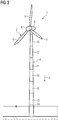
- Fig. 3 shows again the wind turbine 1 according to Fig. 1 .
- the tower 4 has a plurality of tower sections 9 to 13 that are arranged on top of each other.
- the number of tower sections 9 to 13 is arbitrary.
- the tower 4 has a lowest tower section 9 and a topmost tower section 13.
- the nacelle 3 can be attached to the topmost tower section 13.
- the wind turbine 1 has a foundation 14 that can be anchored in the seabed. Between the foundation 14 and the lowest tower section 9 is arranged a transition piece 15.
- the transition piece 15 is a circular or tubular piece that connects the tower 4 to the foundation 14. Thereby, the transition piece 15 forms a transition between the foundation 14 and the tower 4.
- An external platform (not shown) can be attached to the transition piece 14.
- the tower 4 has a longitudinal direction L.
- the longitudinal direction L is oriented from the topmost tower section 13 toward the foundation 14. However, the longitudinal direction L can be oriented vice versa.
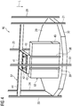
- Figs. 4 to 9 show a platform arrangement 16 according to one embodiment.
- the platform arrangement 16 is arranged inside the transition piece 15.
- the platform arrangement 16 has a circular flange 17 ( Fig. 6 ) that is attached to an upper edge of the transition piece 15. In this way, the platform arrangement 16 is suspended in the transition piece 15.
- An upper platform 18 ( Fig. 6 ) is arranged below the flange 17.
- the upper platform 18 is arranged inside the transition piece 15.
- the upper platform 18 has a platform structure 19 that supports the upper platform 18.
- the platform structure 19 is connected to support beams 20 to 25.
- the support beams 20 to 25 run along the longitudinal direction L of the tower 4.
- the support beams 20 to 25 are connected to the flange 17 by means of attachment elements 26, 27 ( Fig. 6 ).
- the number of attachment elements 26, 27 is the same as the number of support beams 20 to 25.
- a pull in frame 28 is temporary mounted at the upper platform 18 or at the platform structure 19. The pull in frame 28 could be a strong attachment point in a cover of the transition piece 15 as well.
- the platform arrangement 16 also has a lower platform 29.
- the lower platform 29 is supported by means of a platform structure 30.
- the platform structure 30 is attached to the support beams 20 to 25.
- the lower platform 29 has a plurality of hatches or foldable platform plates 31, 32.
- the platform plates 31, 32 can be removed from the lower platform 29 and/or pivoted toward the lower platform 29.
- the platform plates 31, 32 can be pivoted or folded from an open state Z1 ( Figs. 6 , 7 and 8 ) into a closed state Z2 ( Fig. 9 ).
- a switch gear 33 is arranged above the lower platform 29.
- the switch gear 33 is supported by means a carrying unit 34.
- the carrying unit 34 consists of two beams 35, 36 that are arranged perpendicular to the support beams 20 to 25.
- the carrying unit 34 is attached to a suspension structure 37.
- the carrying unit 34 is part of the suspension structure 37.
- the suspension structure 37 consists of two beams 38, 39 that are attached to the beams 35, 36.
- the beams 35, 36 can also be attached to a beam 40 of the platform structure 30.
- the beams 38, 39 are attached to a further beam 41 of the suspension structure 37.
- the beam 41 is arranged in a distance from the beam 40.
- the beam 41 is connected to two beams 42, 43 that run perpendicular to the beam 41.
- the beams 42, 43 are connected to two further beams 44, 45.
- the beam 44 is attached to the support beams 21, 23.
- the beam 45 is connected to the support beam 22.
- the carrying unit 34 and the suspension structure 37 suspend the switch gear 33 from above, namely from the flange 17.
- the carrying unit 34 and the suspension structure 37 make one side of the switch gear 33 suspended from above.
- a load carrying structure around the switch gear 33 is prevented. This enables a direct mounting of an array cable 46 into the switch gear 33.
- the installation process of the array cable 46 can be optimized.
- the function of the platform arrangement 16 is as follows. As can be seen from Figs. 6 to 9 , there is arranged an gastight platform 47 below the lower platform 29. The array cable 46 is guided through the gastight platform 47 in a gastight manner. The array cable 46 is pulled from the gastight platform 47 to the top of the transition piece 15. The pull in frame 28 can be used for this purpose. This can be carried out next to the switch gear 33 by folding up or removing the platform plates 31, 32 into the open state Z1.
- a connector 48 for connecting the array cable 46 to the switch gear 33, a connector 48, in particular a T-connector, is provided.
- the array cable 46 with the connector 48 can then be guided toward a compartment 49 of the switch gear 33 ( Fig. 8 ). Since the platform plates 31, 32 are folded upwards, the array cable 46 with the connector 48 can be routed to the compartment 49 without having any obstacles that block the array cable 46.
- the platform plates 31, 32 can be closed one by one ( Fig. 9 ). Hence, with the closed platform plates 31, 32 it is ensured that the lower platform 29 is again accessible.
- the design of the platform arrangement 16 can be used for any platform of the tower 4.
- the design could also be rotated around the switch gear 33 together with the switch gear 33 for 180° towards the center of the transition piece 15. By that, a center pull of the array cable 46 would be possible and the interface would be more common.
- the top of the switch gear 33 could be used to connect it to the suspension structure 37.
- the carrying unit 34 below the switch gear would then be expendable. This results in more space for routing the array cable 46.
Landscapes
- Engineering & Computer Science (AREA)
- Life Sciences & Earth Sciences (AREA)
- Sustainable Development (AREA)
- Sustainable Energy (AREA)
- Chemical & Material Sciences (AREA)
- Combustion & Propulsion (AREA)
- Mechanical Engineering (AREA)
- General Engineering & Computer Science (AREA)
- Wind Motors (AREA)
Abstract
Description
- The present invention relates to a wind turbine.
- A wind turbine has a tower, a nacelle, which is arranged on top of the tower, a hub with rotor blades being rotatable supported at the nacelle and a generator being provided inside the nacelle and being driven by the hub. Inside the tower can be arranged electrical equipment like a switch gear. To connect the wind turbine to an electrical grid, an array cable is used. Since the array cable is very stiff and the space inside the tower is limited, it is challenging to connect the array cable to the switch gear.
- It is one object of the present invention to provide an improved wind turbine.
- Accordingly, a wind turbine, comprising a tower, a switch gear, which is arranged inside the tower, a suspension structure for a hanging suspension of the switch gear in the tower, and a platform, on which the switch gear is arranged, is provided. The platform has movable platform plates, which are openable for guiding an array cable through the platform to the switch gear.
- In this way, the suspension structure suspends the switch gear from above. A load carrying structure around the switch gear can thus be prevented. This enables a direct mounting of the array cable into the switch gear. The installation process of the array cable can thus be optimized.
- "Switch gear" in this context means an electric and/or electronic component that is part of an electric power system. The switch gear can be composed of electrical disconnect switches, fuses or circuit breakers used to control, protect and isolate electrical equipment. The switch gear can be used both to de-energize equipment to allow work to be done and to clear faults downstream.
- The wind turbine comprises a nacelle that is mounted on or at the tower. Rotor blades are connected to a hub that is supported at the nacelle. A generator is placed inside the nacelle. The generator is connected to the hub. The generator is coupled to the switch gear. The switch gear is supported inside the tower. For this purpose, the suspension structure is provided. "Hanging suspension" in this context preferably means that the suspension structure is hooked into the tower. That means, the switch gear is supported from above by means of the suspension structure. A support from below is not necessary.
- The switch gear is arranged on the platform. However, the platform does preferably not support the weight of the switch gear. The weight of the switch gear is carried by the suspension structure. "Movable" platform plates in this context means that the platform plates can be removed from the platform or can be pivoted around a rotation axis. The platform plates can also be named foldable or pivotable platform plates. The platform plates can be closed as soon as the array cable is guided through the platform.
- Preferably, the wind turbine has a foundation and a transition piece that is arranged between the foundation and the tower and connects the tower to the foundation. Preferably, the switch gear is arranged inside the transition piece. In particular, the platform is also arranged inside the transition piece. Preferably, the suspension structure is suitable for a hanging suspension of the switch gear in the transition piece.
- According to an embodiment, the movable platform plates are pivotable from a closed state into an open state and vice versa.
- This means, the platform plates can be opened and closed as often as needed. The platform plates can be folded from the closed state into the open state and vice versa.
- According to a further embodiment, the suspension structure has a carrying unit that supports the switch gear from below.
- The carrying unit preferably has two beams that are arranged parallel to each other. The beams carry the switch gear. The switch gear is placed on the beams.
- According to a further embodiment, the tower has a foundation, a plurality of tower sections and a transition piece that is arranged between the foundation and a lowest tower section, wherein the switch gear is arranged inside the transition piece.
- The number of tower sections is arbitrary. Besides the lowest tower section, a topmost tower section is provided. The topmost tower section carries the nacelle. The tower sections are attached to each other. The foundation can be anchored in the seabed.
- According to a further embodiment, the suspension structure is suspended in the transition piece.
- In particular, the suspension structure is supported only in or at the transition piece. Preferably, the suspension structure is hooked into the transition piece.
- According to a further embodiment, the wind turbine further comprises a platform arrangement that comprises the suspension structure, the platform and a flange that is connected to the transition piece.
- Preferably, the flange has a circular shape. The flange is connected to an upper edge of the transition piece. The platform is a lower platform of the platform arrangement. Apart from the lower platform, the platform arrangement has an upper platform that is arranged close to the flange.
- According to a further embodiment, the platform arrangement comprises support beams that run along a longitudinal direction of the tower, wherein the support beams are coupled to the suspension structure and to the flange.
- The support beams can be welded or bolted to the suspension structure. The longitudinal direction is oriented from the topmost tower section toward the foundation.
- According to a further embodiment, the support beams are coupled to the flange by means of attachment elements.
- Preferably, each support beam has an attachment element. That means that the number of support beams is the same as the number of attachment elements. The attachment element can be connected to the support beams and the flange in a hinged manner.
- According to a further embodiment, the suspension structure comprises beams that run along the longitudinal direction and beams that run perpendicular to the longitudinal direction, wherein at least some of the beams that run perpendicular to the longitudinal direction are connected to the support beams.
- The beams that run perpendicular to the support beams can be welded or bolted to the support beams. The beams that run along the longitudinal direction and the support beams are preferably arranged parallel to each other.
- According to a further embodiment, the platform arrangement comprises a platform structure that carries the platform and that is connected to the support beams.
- The platform structure can have a circular shape. The support beams carry the platform structure.
- According to a further embodiment, the platform arrangement comprises an upper platform that is arranged parallel to and in a distance from the platform.
- The upper platform is arranged close to the flange. The platforms are arranged parallel to each other.
- According to a further embodiment, the upper platform comprises a pull in frame for pulling in the array cable.
- The pull in frame is preferably connected to a platform structure of the upper platform.
- According to a further embodiment, the platform arrangement comprises a platform structure that carries the upper platform and that is connected to the support beams.
- The support beams carry the platform structure. The platform structure can be made of a plurality of beams.
- According to a further embodiment, the array cable has a connector, in particular a T-connector, that is connectable to the switch gear.
- Preferably, the array cable is part of the wind turbine. By means of the array cable, the wind turbine can be connected to an electrical grid.
- According to a further embodiment, the wind turbine further comprises a gastight platform that is arranged below the platform, wherein the array cable is guided through the gastight platform in a gastight manner.
- The gastight platform prevents gas from entering the tower from the seabed.
- Further possible implementations or alternative solutions of the invention also encompass combinations - that are not explicitly mentioned herein - of features described above or below with regard to the embodiments. The person skilled in the art may also add individual or isolated aspects and features to the most basic form of the invention.
- Further embodiments, features and advantages of the present invention will become apparent from the subsequent description and dependent claims, taken in conjunction with the accompanying drawings, in which:
- Fig. 1
- shows a perspective view of a wind turbine according to one embodiment;
- Fig. 2
- shows a perspective view of a wind turbine rotor blade according to one embodiment;
- Fig. 3
- shows a further perspective view of the wind turbine according to
Fig. 1 ; - Fig. 4
- shows a perspective view of a platform arrangement according to one embodiment;
- Fig. 5
- shows a further perspective view of the platform arrangement according to
Fig. 4 ; - Fig. 6
- shows a further perspective view of the platform arrangement according to
Fig. 4 ; - Fig. 7
- shows a further perspective view of the platform arrangement according to
Fig. 4 ; - Fig. 8
- shows a further perspective view of the platform arrangement according to
Fig. 4 ; and - Fig. 9
- shows a further perspective view of the platform arrangement according to
Fig. 4 . - In the Figures, like reference numerals designate like or functionally equivalent elements, unless otherwise indicated.
-
Fig. 1 shows awind turbine 1 according to one embodiment. - The
wind turbine 1 comprises arotor 2 connected to a generator (not shown) arranged inside anacelle 3. Thenacelle 3 is arranged at the upper end of a tower 4 of thewind turbine 1. The tower 4 has a plurality of tower sections that are arranged on top of each other. The tower 4 can be named wind turbine tower. - The
rotor 2 comprises threerotor blades 5. Therotor blades 5 are connected to ahub 6 of thewind turbine 1.Rotors 2 of this kind may have diameters ranging from, for example, 30 to 160 meters or even more. Therotor blades 5 are subjected to high wind loads. At the same time, therotor blades 5 need to be lightweight. For these reasons,rotor blades 5 inmodern wind turbines 1 are manufactured from fiber-reinforced composite materials. Therein, glass fibers are generally preferred over carbon fibers for cost reasons. Oftentimes, glass fibers in the form of unidirectional fiber mats are used. -
Fig. 2 shows arotor blade 5 according to one embodiment. - The
rotor blade 5 comprises an aerodynamically designedportion 7, which is shaped for optimum exploitation of the wind energy and a blade root 8 for connecting therotor blade 5 to thehub 6. -
Fig. 3 shows again thewind turbine 1 according toFig. 1 . - As mentioned before, the tower 4 has a plurality of
tower sections 9 to 13 that are arranged on top of each other. The number oftower sections 9 to 13 is arbitrary. The tower 4 has alowest tower section 9 and atopmost tower section 13. Thenacelle 3 can be attached to thetopmost tower section 13. Thewind turbine 1 has a foundation 14 that can be anchored in the seabed. Between the foundation 14 and thelowest tower section 9 is arranged atransition piece 15. - The
transition piece 15 is a circular or tubular piece that connects the tower 4 to the foundation 14. Thereby, thetransition piece 15 forms a transition between the foundation 14 and the tower 4. An external platform (not shown) can be attached to the transition piece 14. The tower 4 has a longitudinal direction L. The longitudinal direction L is oriented from thetopmost tower section 13 toward the foundation 14. However, the longitudinal direction L can be oriented vice versa. -
Figs. 4 to 9 show aplatform arrangement 16 according to one embodiment. - The
platform arrangement 16 is arranged inside thetransition piece 15. Theplatform arrangement 16 has a circular flange 17 (Fig. 6 ) that is attached to an upper edge of thetransition piece 15. In this way, theplatform arrangement 16 is suspended in thetransition piece 15. - An upper platform 18 (
Fig. 6 ) is arranged below theflange 17. Theupper platform 18 is arranged inside thetransition piece 15. Theupper platform 18 has aplatform structure 19 that supports theupper platform 18. Theplatform structure 19 is connected to supportbeams 20 to 25. The support beams 20 to 25 run along the longitudinal direction L of the tower 4. - The support beams 20 to 25 are connected to the
flange 17 by means ofattachment elements 26, 27 (Fig. 6 ). Preferably, the number ofattachment elements frame 28 is temporary mounted at theupper platform 18 or at theplatform structure 19. The pull inframe 28 could be a strong attachment point in a cover of thetransition piece 15 as well. - The
platform arrangement 16 also has alower platform 29. Thelower platform 29 is supported by means of aplatform structure 30. Theplatform structure 30 is attached to the support beams 20 to 25. Thelower platform 29 has a plurality of hatches orfoldable platform plates platform plates lower platform 29 and/or pivoted toward thelower platform 29. In particular, theplatform plates Figs. 6 ,7 and8 ) into a closed state Z2 (Fig. 9 ). - A
switch gear 33 is arranged above thelower platform 29. Theswitch gear 33 is supported by means a carryingunit 34. The carryingunit 34 consists of twobeams unit 34 is attached to asuspension structure 37. The carryingunit 34 is part of thesuspension structure 37. Thesuspension structure 37 consists of twobeams beams beams beam 40 of theplatform structure 30. - The
beams further beam 41 of thesuspension structure 37. Thebeam 41 is arranged in a distance from thebeam 40. Thebeam 41 is connected to twobeams beam 41. Thebeams further beams beam 44 is attached to the support beams 21, 23. Thebeam 45 is connected to thesupport beam 22. - In this way, the carrying
unit 34 and thesuspension structure 37 suspend theswitch gear 33 from above, namely from theflange 17. The carryingunit 34 and thesuspension structure 37 make one side of theswitch gear 33 suspended from above. A load carrying structure around theswitch gear 33 is prevented. This enables a direct mounting of anarray cable 46 into theswitch gear 33. The installation process of thearray cable 46 can be optimized. - The function of the
platform arrangement 16 is as follows. As can be seen fromFigs. 6 to 9 , there is arranged angastight platform 47 below thelower platform 29. Thearray cable 46 is guided through thegastight platform 47 in a gastight manner. Thearray cable 46 is pulled from thegastight platform 47 to the top of thetransition piece 15. The pull inframe 28 can be used for this purpose. This can be carried out next to theswitch gear 33 by folding up or removing theplatform plates - Once the
array cable 46 has been pulled in and needs to be installed in theswitch gear 33, thefoldable platform plates Fig. 7 ). For connecting thearray cable 46 to theswitch gear 33, aconnector 48, in particular a T-connector, is provided. - The
array cable 46 with theconnector 48 can then be guided toward acompartment 49 of the switch gear 33 (Fig. 8 ). Since theplatform plates array cable 46 with theconnector 48 can be routed to thecompartment 49 without having any obstacles that block thearray cable 46. - When the
connector 48 of thearray cable 46 is finally installed in theswitch gear 33, theplatform plates Fig. 9 ). Hence, with theclosed platform plates lower platform 29 is again accessible. - The design of the
platform arrangement 16 can be used for any platform of the tower 4. The design could also be rotated around theswitch gear 33 together with theswitch gear 33 for 180° towards the center of thetransition piece 15. By that, a center pull of thearray cable 46 would be possible and the interface would be more common. Also the top of theswitch gear 33 could be used to connect it to thesuspension structure 37. The carryingunit 34 below the switch gear would then be expendable. This results in more space for routing thearray cable 46. - Although the present invention has been described in accordance with preferred embodiments, it is obvious for the person skilled in the art that modifications are possible in all embodiments.
Claims (15)
- A wind turbine (1), comprising a tower (4), a switch gear (33), which is arranged inside the tower (4), a suspension structure (37) for a hanging suspension of the switch gear (33) in the tower (4), and a platform (29), on which the switch gear (33) is arranged, wherein the platform (29) has movable platform plates (31, 32), which are openable for guiding an array cable (46) through the platform (29) to the switch gear (33).
- The wind turbine according to claim 1, wherein the movable platform plates (31, 32) are pivotable from a closed state (Z2) into an open state (Z1) and vice versa.
- The wind turbine according to claim 1 or 2, wherein the suspension structure (37) has a carrying unit (34) that supports the switch gear (33) from below.
- The wind turbine according to one of claims 1 - 3, wherein the tower (4) has a foundation (14), a plurality of tower sections (9 - 13) and a transition piece (15) that is arranged between the foundation (14) and a lowest tower section (9), wherein the switch gear (33) is arranged inside the transition piece (15).
- The wind turbine according to claim 4, wherein the suspension structure (37) is suspended in the transition piece (15).
- The wind turbine according to claim 4 or 5, further comprising a platform arrangement (16) that comprises the suspension structure (37), the platform (29) and a flange (17) that is connected to the transition piece (15).
- The wind turbine according to claim 6, wherein the platform arrangement (16) comprises support beams (20 - 25) that run along a longitudinal direction (L) of the tower (4), wherein the support beams (20 - 25) are coupled to the suspension structure (37) and to the flange (17).
- The wind turbine according to claim 7, wherein the support beams (20 - 25) are coupled to the flange (17) by means of attachment elements (26, 27).
- The wind turbine according to claim 7 or 8, wherein the suspension structure (37) comprises beams (38, 39) that run along the longitudinal direction (L) and beams (41 - 45) that run perpendicular to the longitudinal direction (L), wherein at least some of the beams (41 - 45) that run perpendicular to the longitudinal direction (L) are connected to the support beams (20 - 25).
- The wind turbine according to one of claims 6 - 9, wherein the platform arrangement (16) comprises a platform structure (30) that carries the platform (29) and that is connected to the support beams (20 - 25).
- The wind turbine according to one of claims 6 - 10, wherein the platform arrangement (16) comprises an upper platform (18) that is arranged parallel to and in a distance from the platform (29).
- The wind turbine according to claim 11, wherein the upper platform (18) comprises a pull in frame (28) for pulling in the array cable (46).
- The wind turbine according to claim 11 or 12, wherein the platform arrangement (16) comprises a platform structure (19) that carries the upper platform (18) and that is connected to the support beams (20 - 25).
- The wind turbine according to one of claims 1 - 13, wherein the array cable (46) has a connector (48), in particular a T-connector, that is connectable to the switch gear (33).
- The wind turbine according to one of claims 1 - 14, further comprising a gastight platform (47) that is arranged below the platform (29), wherein the array cable (46) is guided through the gastight platform (47) in a gastight manner.
Priority Applications (1)
| Application Number | Priority Date | Filing Date | Title |
|---|---|---|---|
| EP20161895.6A EP3879095B1 (en) | 2020-03-09 | 2020-03-09 | Wind turbine |
Applications Claiming Priority (1)
| Application Number | Priority Date | Filing Date | Title |
|---|---|---|---|
| EP20161895.6A EP3879095B1 (en) | 2020-03-09 | 2020-03-09 | Wind turbine |
Publications (2)
| Publication Number | Publication Date |
|---|---|
| EP3879095A1 true EP3879095A1 (en) | 2021-09-15 |
| EP3879095B1 EP3879095B1 (en) | 2023-06-28 |
Family
ID=69941145
Family Applications (1)
| Application Number | Title | Priority Date | Filing Date |
|---|---|---|---|
| EP20161895.6A Active EP3879095B1 (en) | 2020-03-09 | 2020-03-09 | Wind turbine |
Country Status (1)
| Country | Link |
|---|---|
| EP (1) | EP3879095B1 (en) |
Cited By (1)
| Publication number | Priority date | Publication date | Assignee | Title |
|---|---|---|---|---|
| EP4650596A1 (en) * | 2024-05-16 | 2025-11-19 | Siemens Gamesa Renewable Energy A/S | Lower and upper tower section for a tower of a wind turbine, tower, wind turbine and method for manufacturing a tower of a wind turbine |
Citations (4)
| Publication number | Priority date | Publication date | Assignee | Title |
|---|---|---|---|---|
| US20110221205A1 (en) * | 2008-11-16 | 2011-09-15 | Siemens Aktiengesellschaft | Device comprising rigid connecting bars for the conducting connection of first to second busbars |
| WO2013182205A1 (en) * | 2012-06-08 | 2013-12-12 | Vestas Wind Systems A/S | Arragnement of a switchgear in a tower of a wind turbine |
| EP3438449A1 (en) * | 2017-08-04 | 2019-02-06 | GeoSea NV | Self-supporting support structure for wind turbine equipment |
| EP3502353A1 (en) * | 2017-12-22 | 2019-06-26 | Siemens Gamesa Renewable Energy A/S | Foundation building system for an offshore wind turbine and method for installation of an offshore wind turbine |
-
2020
- 2020-03-09 EP EP20161895.6A patent/EP3879095B1/en active Active
Patent Citations (4)
| Publication number | Priority date | Publication date | Assignee | Title |
|---|---|---|---|---|
| US20110221205A1 (en) * | 2008-11-16 | 2011-09-15 | Siemens Aktiengesellschaft | Device comprising rigid connecting bars for the conducting connection of first to second busbars |
| WO2013182205A1 (en) * | 2012-06-08 | 2013-12-12 | Vestas Wind Systems A/S | Arragnement of a switchgear in a tower of a wind turbine |
| EP3438449A1 (en) * | 2017-08-04 | 2019-02-06 | GeoSea NV | Self-supporting support structure for wind turbine equipment |
| EP3502353A1 (en) * | 2017-12-22 | 2019-06-26 | Siemens Gamesa Renewable Energy A/S | Foundation building system for an offshore wind turbine and method for installation of an offshore wind turbine |
Cited By (2)
| Publication number | Priority date | Publication date | Assignee | Title |
|---|---|---|---|---|
| EP4650596A1 (en) * | 2024-05-16 | 2025-11-19 | Siemens Gamesa Renewable Energy A/S | Lower and upper tower section for a tower of a wind turbine, tower, wind turbine and method for manufacturing a tower of a wind turbine |
| WO2025237608A1 (en) * | 2024-05-16 | 2025-11-20 | Siemens Gamesa Renewable Energy A/S | Lower and upper tower section for a tower of a wind turbine, tower, wind turbine and method for manufacturing a tower of a wind turbine |
Also Published As
| Publication number | Publication date |
|---|---|
| EP3879095B1 (en) | 2023-06-28 |
Similar Documents
| Publication | Publication Date | Title |
|---|---|---|
| EP2063119A2 (en) | Module of a nacelle of a wind turbine and method of assembly | |
| EP2143937A2 (en) | Cable bridge for a wind turbine tower | |
| JP4335214B2 (en) | Rotor blade mounting method and wind turbine rotor blade | |
| EP3276169A1 (en) | A wind turbine | |
| JP2016509157A (en) | Wind turbine for power generation using naval technology | |
| AU2020333165B2 (en) | Floating wind turbine comprising an integrated electrical substation | |
| WO2012105971A1 (en) | Nacelle-mounted maintenance system for wind turbines | |
| EP3891387B1 (en) | Wind turbine tower transition piece | |
| US11817813B2 (en) | Wind turbine electric filter comprising filter modules arranged at different platform heights inside a wind turbine tower | |
| US20230143859A1 (en) | A wind power plant | |
| EP3879095B1 (en) | Wind turbine | |
| CN113614365B (en) | Wind turbine and method for mounting a platform to a wall section of a wind turbine | |
| US11859592B2 (en) | Wind turbine | |
| CN101588059B (en) | Lightning protection-grounding integrated protection system | |
| EP4261404B1 (en) | Wind turbine frame with flexible coupling | |
| US11629703B2 (en) | Wind turbine nacelle structure and a method of assembling a wind turbine nacelle structure | |
| EP4198302A1 (en) | Wind turbine with segmented cable arrangement | |
| EP3431756B1 (en) | Method for replacing a generator frame of a wind turbine | |
| NZ783421B2 (en) | Floating wind turbine comprising an integrated electrical substation | |
| RU2513863C1 (en) | Wind rotor with inclined turbine-generator block | |
| CN115076036A (en) | Cable guide assembly and method for wind turbine |
Legal Events
| Date | Code | Title | Description |
|---|---|---|---|
| PUAI | Public reference made under article 153(3) epc to a published international application that has entered the european phase |
Free format text: ORIGINAL CODE: 0009012 |
|
| STAA | Information on the status of an ep patent application or granted ep patent |
Free format text: STATUS: THE APPLICATION HAS BEEN PUBLISHED |
|
| AK | Designated contracting states |
Kind code of ref document: A1 Designated state(s): AL AT BE BG CH CY CZ DE DK EE ES FI FR GB GR HR HU IE IS IT LI LT LU LV MC MK MT NL NO PL PT RO RS SE SI SK SM TR |
|
| STAA | Information on the status of an ep patent application or granted ep patent |
Free format text: STATUS: REQUEST FOR EXAMINATION WAS MADE |
|
| 17P | Request for examination filed |
Effective date: 20220315 |
|
| RBV | Designated contracting states (corrected) |
Designated state(s): AL AT BE BG CH CY CZ DE DK EE ES FI FR GB GR HR HU IE IS IT LI LT LU LV MC MK MT NL NO PL PT RO RS SE SI SK SM TR |
|
| GRAP | Despatch of communication of intention to grant a patent |
Free format text: ORIGINAL CODE: EPIDOSNIGR1 |
|
| STAA | Information on the status of an ep patent application or granted ep patent |
Free format text: STATUS: GRANT OF PATENT IS INTENDED |
|
| INTG | Intention to grant announced |
Effective date: 20230223 |
|
| GRAS | Grant fee paid |
Free format text: ORIGINAL CODE: EPIDOSNIGR3 |
|
| GRAA | (expected) grant |
Free format text: ORIGINAL CODE: 0009210 |
|
| STAA | Information on the status of an ep patent application or granted ep patent |
Free format text: STATUS: THE PATENT HAS BEEN GRANTED |
|
| AK | Designated contracting states |
Kind code of ref document: B1 Designated state(s): AL AT BE BG CH CY CZ DE DK EE ES FI FR GB GR HR HU IE IS IT LI LT LU LV MC MK MT NL NO PL PT RO RS SE SI SK SM TR |
|
| REG | Reference to a national code |
Ref country code: CH Ref legal event code: EP |
|
| REG | Reference to a national code |
Ref country code: AT Ref legal event code: REF Ref document number: 1582890 Country of ref document: AT Kind code of ref document: T Effective date: 20230715 |
|
| REG | Reference to a national code |
Ref country code: IE Ref legal event code: FG4D |
|
| REG | Reference to a national code |
Ref country code: DE Ref legal event code: R096 Ref document number: 602020012898 Country of ref document: DE |
|
| REG | Reference to a national code |
Ref country code: NL Ref legal event code: FP |
|
| REG | Reference to a national code |
Ref country code: LT Ref legal event code: MG9D |
|
| PG25 | Lapsed in a contracting state [announced via postgrant information from national office to epo] |
Ref country code: SE Free format text: LAPSE BECAUSE OF FAILURE TO SUBMIT A TRANSLATION OF THE DESCRIPTION OR TO PAY THE FEE WITHIN THE PRESCRIBED TIME-LIMIT Effective date: 20230628 Ref country code: NO Free format text: LAPSE BECAUSE OF FAILURE TO SUBMIT A TRANSLATION OF THE DESCRIPTION OR TO PAY THE FEE WITHIN THE PRESCRIBED TIME-LIMIT Effective date: 20230928 |
|
| REG | Reference to a national code |
Ref country code: AT Ref legal event code: MK05 Ref document number: 1582890 Country of ref document: AT Kind code of ref document: T Effective date: 20230628 |
|
| PG25 | Lapsed in a contracting state [announced via postgrant information from national office to epo] |
Ref country code: RS Free format text: LAPSE BECAUSE OF FAILURE TO SUBMIT A TRANSLATION OF THE DESCRIPTION OR TO PAY THE FEE WITHIN THE PRESCRIBED TIME-LIMIT Effective date: 20230628 Ref country code: LV Free format text: LAPSE BECAUSE OF FAILURE TO SUBMIT A TRANSLATION OF THE DESCRIPTION OR TO PAY THE FEE WITHIN THE PRESCRIBED TIME-LIMIT Effective date: 20230628 Ref country code: LT Free format text: LAPSE BECAUSE OF FAILURE TO SUBMIT A TRANSLATION OF THE DESCRIPTION OR TO PAY THE FEE WITHIN THE PRESCRIBED TIME-LIMIT Effective date: 20230628 Ref country code: HR Free format text: LAPSE BECAUSE OF FAILURE TO SUBMIT A TRANSLATION OF THE DESCRIPTION OR TO PAY THE FEE WITHIN THE PRESCRIBED TIME-LIMIT Effective date: 20230628 Ref country code: GR Free format text: LAPSE BECAUSE OF FAILURE TO SUBMIT A TRANSLATION OF THE DESCRIPTION OR TO PAY THE FEE WITHIN THE PRESCRIBED TIME-LIMIT Effective date: 20230929 |
|
| PG25 | Lapsed in a contracting state [announced via postgrant information from national office to epo] |
Ref country code: FI Free format text: LAPSE BECAUSE OF FAILURE TO SUBMIT A TRANSLATION OF THE DESCRIPTION OR TO PAY THE FEE WITHIN THE PRESCRIBED TIME-LIMIT Effective date: 20230628 |
|
| PG25 | Lapsed in a contracting state [announced via postgrant information from national office to epo] |
Ref country code: SK Free format text: LAPSE BECAUSE OF FAILURE TO SUBMIT A TRANSLATION OF THE DESCRIPTION OR TO PAY THE FEE WITHIN THE PRESCRIBED TIME-LIMIT Effective date: 20230628 |
|
| PG25 | Lapsed in a contracting state [announced via postgrant information from national office to epo] |
Ref country code: ES Free format text: LAPSE BECAUSE OF FAILURE TO SUBMIT A TRANSLATION OF THE DESCRIPTION OR TO PAY THE FEE WITHIN THE PRESCRIBED TIME-LIMIT Effective date: 20230628 |
|
| PG25 | Lapsed in a contracting state [announced via postgrant information from national office to epo] |
Ref country code: IS Free format text: LAPSE BECAUSE OF FAILURE TO SUBMIT A TRANSLATION OF THE DESCRIPTION OR TO PAY THE FEE WITHIN THE PRESCRIBED TIME-LIMIT Effective date: 20231028 |
|
| PG25 | Lapsed in a contracting state [announced via postgrant information from national office to epo] |
Ref country code: SM Free format text: LAPSE BECAUSE OF FAILURE TO SUBMIT A TRANSLATION OF THE DESCRIPTION OR TO PAY THE FEE WITHIN THE PRESCRIBED TIME-LIMIT Effective date: 20230628 Ref country code: SK Free format text: LAPSE BECAUSE OF FAILURE TO SUBMIT A TRANSLATION OF THE DESCRIPTION OR TO PAY THE FEE WITHIN THE PRESCRIBED TIME-LIMIT Effective date: 20230628 Ref country code: RO Free format text: LAPSE BECAUSE OF FAILURE TO SUBMIT A TRANSLATION OF THE DESCRIPTION OR TO PAY THE FEE WITHIN THE PRESCRIBED TIME-LIMIT Effective date: 20230628 Ref country code: PT Free format text: LAPSE BECAUSE OF FAILURE TO SUBMIT A TRANSLATION OF THE DESCRIPTION OR TO PAY THE FEE WITHIN THE PRESCRIBED TIME-LIMIT Effective date: 20231030 Ref country code: IS Free format text: LAPSE BECAUSE OF FAILURE TO SUBMIT A TRANSLATION OF THE DESCRIPTION OR TO PAY THE FEE WITHIN THE PRESCRIBED TIME-LIMIT Effective date: 20231028 Ref country code: ES Free format text: LAPSE BECAUSE OF FAILURE TO SUBMIT A TRANSLATION OF THE DESCRIPTION OR TO PAY THE FEE WITHIN THE PRESCRIBED TIME-LIMIT Effective date: 20230628 Ref country code: EE Free format text: LAPSE BECAUSE OF FAILURE TO SUBMIT A TRANSLATION OF THE DESCRIPTION OR TO PAY THE FEE WITHIN THE PRESCRIBED TIME-LIMIT Effective date: 20230628 Ref country code: CZ Free format text: LAPSE BECAUSE OF FAILURE TO SUBMIT A TRANSLATION OF THE DESCRIPTION OR TO PAY THE FEE WITHIN THE PRESCRIBED TIME-LIMIT Effective date: 20230628 Ref country code: AT Free format text: LAPSE BECAUSE OF FAILURE TO SUBMIT A TRANSLATION OF THE DESCRIPTION OR TO PAY THE FEE WITHIN THE PRESCRIBED TIME-LIMIT Effective date: 20230628 |
|
| PG25 | Lapsed in a contracting state [announced via postgrant information from national office to epo] |
Ref country code: PL Free format text: LAPSE BECAUSE OF FAILURE TO SUBMIT A TRANSLATION OF THE DESCRIPTION OR TO PAY THE FEE WITHIN THE PRESCRIBED TIME-LIMIT Effective date: 20230628 |
|
| REG | Reference to a national code |
Ref country code: DE Ref legal event code: R097 Ref document number: 602020012898 Country of ref document: DE |
|
| PG25 | Lapsed in a contracting state [announced via postgrant information from national office to epo] |
Ref country code: DK Free format text: LAPSE BECAUSE OF FAILURE TO SUBMIT A TRANSLATION OF THE DESCRIPTION OR TO PAY THE FEE WITHIN THE PRESCRIBED TIME-LIMIT Effective date: 20230628 |
|
| PLBE | No opposition filed within time limit |
Free format text: ORIGINAL CODE: 0009261 |
|
| STAA | Information on the status of an ep patent application or granted ep patent |
Free format text: STATUS: NO OPPOSITION FILED WITHIN TIME LIMIT |
|
| PG25 | Lapsed in a contracting state [announced via postgrant information from national office to epo] |
Ref country code: IT Free format text: LAPSE BECAUSE OF FAILURE TO SUBMIT A TRANSLATION OF THE DESCRIPTION OR TO PAY THE FEE WITHIN THE PRESCRIBED TIME-LIMIT Effective date: 20230628 |
|
| 26N | No opposition filed |
Effective date: 20240402 |
|
| PG25 | Lapsed in a contracting state [announced via postgrant information from national office to epo] |
Ref country code: SI Free format text: LAPSE BECAUSE OF FAILURE TO SUBMIT A TRANSLATION OF THE DESCRIPTION OR TO PAY THE FEE WITHIN THE PRESCRIBED TIME-LIMIT Effective date: 20230628 |
|
| REG | Reference to a national code |
Ref country code: DE Ref legal event code: R119 Ref document number: 602020012898 Country of ref document: DE |
|
| REG | Reference to a national code |
Ref country code: CH Ref legal event code: PL |
|
| REG | Reference to a national code |
Ref country code: NL Ref legal event code: MM Effective date: 20240401 |
|
| PG25 | Lapsed in a contracting state [announced via postgrant information from national office to epo] |
Ref country code: BG Free format text: LAPSE BECAUSE OF FAILURE TO SUBMIT A TRANSLATION OF THE DESCRIPTION OR TO PAY THE FEE WITHIN THE PRESCRIBED TIME-LIMIT Effective date: 20230628 |
|
| PG25 | Lapsed in a contracting state [announced via postgrant information from national office to epo] |
Ref country code: LU Free format text: LAPSE BECAUSE OF NON-PAYMENT OF DUE FEES Effective date: 20240309 |
|
| PG25 | Lapsed in a contracting state [announced via postgrant information from national office to epo] |
Ref country code: MC Free format text: LAPSE BECAUSE OF FAILURE TO SUBMIT A TRANSLATION OF THE DESCRIPTION OR TO PAY THE FEE WITHIN THE PRESCRIBED TIME-LIMIT Effective date: 20230628 |
|
| GBPC | Gb: european patent ceased through non-payment of renewal fee |
Effective date: 20240309 |
|
| PG25 | Lapsed in a contracting state [announced via postgrant information from national office to epo] |
Ref country code: MC Free format text: LAPSE BECAUSE OF FAILURE TO SUBMIT A TRANSLATION OF THE DESCRIPTION OR TO PAY THE FEE WITHIN THE PRESCRIBED TIME-LIMIT Effective date: 20230628 Ref country code: LU Free format text: LAPSE BECAUSE OF NON-PAYMENT OF DUE FEES Effective date: 20240309 Ref country code: BG Free format text: LAPSE BECAUSE OF FAILURE TO SUBMIT A TRANSLATION OF THE DESCRIPTION OR TO PAY THE FEE WITHIN THE PRESCRIBED TIME-LIMIT Effective date: 20230628 |
|
| PG25 | Lapsed in a contracting state [announced via postgrant information from national office to epo] |
Ref country code: NL Free format text: LAPSE BECAUSE OF NON-PAYMENT OF DUE FEES Effective date: 20240401 |
|
| REG | Reference to a national code |
Ref country code: BE Ref legal event code: MM Effective date: 20240331 |
|
| PG25 | Lapsed in a contracting state [announced via postgrant information from national office to epo] |
Ref country code: NL Free format text: LAPSE BECAUSE OF NON-PAYMENT OF DUE FEES Effective date: 20240401 |
|
| PG25 | Lapsed in a contracting state [announced via postgrant information from national office to epo] |
Ref country code: DE Free format text: LAPSE BECAUSE OF NON-PAYMENT OF DUE FEES Effective date: 20241001 |
|
| PG25 | Lapsed in a contracting state [announced via postgrant information from national office to epo] |
Ref country code: BE Free format text: LAPSE BECAUSE OF NON-PAYMENT OF DUE FEES Effective date: 20240331 |
|
| PG25 | Lapsed in a contracting state [announced via postgrant information from national office to epo] |
Ref country code: GB Free format text: LAPSE BECAUSE OF NON-PAYMENT OF DUE FEES Effective date: 20240309 |
|
| PG25 | Lapsed in a contracting state [announced via postgrant information from national office to epo] |
Ref country code: FR Free format text: LAPSE BECAUSE OF NON-PAYMENT OF DUE FEES Effective date: 20240331 |
|
| PG25 | Lapsed in a contracting state [announced via postgrant information from national office to epo] |
Ref country code: IE Free format text: LAPSE BECAUSE OF NON-PAYMENT OF DUE FEES Effective date: 20240309 |
|
| PG25 | Lapsed in a contracting state [announced via postgrant information from national office to epo] |
Ref country code: IE Free format text: LAPSE BECAUSE OF NON-PAYMENT OF DUE FEES Effective date: 20240309 Ref country code: GB Free format text: LAPSE BECAUSE OF NON-PAYMENT OF DUE FEES Effective date: 20240309 Ref country code: FR Free format text: LAPSE BECAUSE OF NON-PAYMENT OF DUE FEES Effective date: 20240331 Ref country code: DE Free format text: LAPSE BECAUSE OF NON-PAYMENT OF DUE FEES Effective date: 20241001 Ref country code: BE Free format text: LAPSE BECAUSE OF NON-PAYMENT OF DUE FEES Effective date: 20240331 Ref country code: CH Free format text: LAPSE BECAUSE OF NON-PAYMENT OF DUE FEES Effective date: 20240331 |
|
| PG25 | Lapsed in a contracting state [announced via postgrant information from national office to epo] |
Ref country code: CY Free format text: LAPSE BECAUSE OF FAILURE TO SUBMIT A TRANSLATION OF THE DESCRIPTION OR TO PAY THE FEE WITHIN THE PRESCRIBED TIME-LIMIT; INVALID AB INITIO Effective date: 20200309 |
|
| PG25 | Lapsed in a contracting state [announced via postgrant information from national office to epo] |
Ref country code: HU Free format text: LAPSE BECAUSE OF FAILURE TO SUBMIT A TRANSLATION OF THE DESCRIPTION OR TO PAY THE FEE WITHIN THE PRESCRIBED TIME-LIMIT; INVALID AB INITIO Effective date: 20200309 |
|
| PG25 | Lapsed in a contracting state [announced via postgrant information from national office to epo] |
Ref country code: TR Free format text: LAPSE BECAUSE OF FAILURE TO SUBMIT A TRANSLATION OF THE DESCRIPTION OR TO PAY THE FEE WITHIN THE PRESCRIBED TIME-LIMIT Effective date: 20230628 |