EP3879080A1 - Modular bearing component - Google Patents
Modular bearing component Download PDFInfo
- Publication number
- EP3879080A1 EP3879080A1 EP21162350.9A EP21162350A EP3879080A1 EP 3879080 A1 EP3879080 A1 EP 3879080A1 EP 21162350 A EP21162350 A EP 21162350A EP 3879080 A1 EP3879080 A1 EP 3879080A1
- Authority
- EP
- European Patent Office
- Prior art keywords
- shaft
- compartment
- bearing
- bearing compartment
- axial end
- Prior art date
- Legal status (The legal status is an assumption and is not a legal conclusion. Google has not performed a legal analysis and makes no representation as to the accuracy of the status listed.)
- Granted
Links
Images


Classifications
-
- F—MECHANICAL ENGINEERING; LIGHTING; HEATING; WEAPONS; BLASTING
- F01—MACHINES OR ENGINES IN GENERAL; ENGINE PLANTS IN GENERAL; STEAM ENGINES
- F01D—NON-POSITIVE DISPLACEMENT MACHINES OR ENGINES, e.g. STEAM TURBINES
- F01D25/00—Component parts, details, or accessories, not provided for in, or of interest apart from, other groups
- F01D25/16—Arrangement of bearings; Supporting or mounting bearings in casings
-
- F—MECHANICAL ENGINEERING; LIGHTING; HEATING; WEAPONS; BLASTING
- F01—MACHINES OR ENGINES IN GENERAL; ENGINE PLANTS IN GENERAL; STEAM ENGINES
- F01D—NON-POSITIVE DISPLACEMENT MACHINES OR ENGINES, e.g. STEAM TURBINES
- F01D25/00—Component parts, details, or accessories, not provided for in, or of interest apart from, other groups
- F01D25/18—Lubricating arrangements
-
- F—MECHANICAL ENGINEERING; LIGHTING; HEATING; WEAPONS; BLASTING
- F02—COMBUSTION ENGINES; HOT-GAS OR COMBUSTION-PRODUCT ENGINE PLANTS
- F02C—GAS-TURBINE PLANTS; AIR INTAKES FOR JET-PROPULSION PLANTS; CONTROLLING FUEL SUPPLY IN AIR-BREATHING JET-PROPULSION PLANTS
- F02C7/00—Features, components parts, details or accessories, not provided for in, or of interest apart form groups F02C1/00 - F02C6/00; Air intakes for jet-propulsion plants
- F02C7/06—Arrangements of bearings; Lubricating
-
- F—MECHANICAL ENGINEERING; LIGHTING; HEATING; WEAPONS; BLASTING
- F16—ENGINEERING ELEMENTS AND UNITS; GENERAL MEASURES FOR PRODUCING AND MAINTAINING EFFECTIVE FUNCTIONING OF MACHINES OR INSTALLATIONS; THERMAL INSULATION IN GENERAL
- F16C—SHAFTS; FLEXIBLE SHAFTS; ELEMENTS OR CRANKSHAFT MECHANISMS; ROTARY BODIES OTHER THAN GEARING ELEMENTS; BEARINGS
- F16C19/00—Bearings with rolling contact, for exclusively rotary movement
- F16C19/22—Bearings with rolling contact, for exclusively rotary movement with bearing rollers essentially of the same size in one or more circular rows, e.g. needle bearings
- F16C19/34—Bearings with rolling contact, for exclusively rotary movement with bearing rollers essentially of the same size in one or more circular rows, e.g. needle bearings for both radial and axial load
- F16C19/38—Bearings with rolling contact, for exclusively rotary movement with bearing rollers essentially of the same size in one or more circular rows, e.g. needle bearings for both radial and axial load with two or more rows of rollers
- F16C19/383—Bearings with rolling contact, for exclusively rotary movement with bearing rollers essentially of the same size in one or more circular rows, e.g. needle bearings for both radial and axial load with two or more rows of rollers with tapered rollers, i.e. rollers having essentially the shape of a truncated cone
-
- F—MECHANICAL ENGINEERING; LIGHTING; HEATING; WEAPONS; BLASTING
- F05—INDEXING SCHEMES RELATING TO ENGINES OR PUMPS IN VARIOUS SUBCLASSES OF CLASSES F01-F04
- F05D—INDEXING SCHEME FOR ASPECTS RELATING TO NON-POSITIVE-DISPLACEMENT MACHINES OR ENGINES, GAS-TURBINES OR JET-PROPULSION PLANTS
- F05D2230/00—Manufacture
- F05D2230/60—Assembly methods
-
- F—MECHANICAL ENGINEERING; LIGHTING; HEATING; WEAPONS; BLASTING
- F05—INDEXING SCHEMES RELATING TO ENGINES OR PUMPS IN VARIOUS SUBCLASSES OF CLASSES F01-F04
- F05D—INDEXING SCHEME FOR ASPECTS RELATING TO NON-POSITIVE-DISPLACEMENT MACHINES OR ENGINES, GAS-TURBINES OR JET-PROPULSION PLANTS
- F05D2240/00—Components
- F05D2240/50—Bearings
-
- F—MECHANICAL ENGINEERING; LIGHTING; HEATING; WEAPONS; BLASTING
- F05—INDEXING SCHEMES RELATING TO ENGINES OR PUMPS IN VARIOUS SUBCLASSES OF CLASSES F01-F04
- F05D—INDEXING SCHEME FOR ASPECTS RELATING TO NON-POSITIVE-DISPLACEMENT MACHINES OR ENGINES, GAS-TURBINES OR JET-PROPULSION PLANTS
- F05D2240/00—Components
- F05D2240/50—Bearings
- F05D2240/54—Radial bearings
-
- F—MECHANICAL ENGINEERING; LIGHTING; HEATING; WEAPONS; BLASTING
- F05—INDEXING SCHEMES RELATING TO ENGINES OR PUMPS IN VARIOUS SUBCLASSES OF CLASSES F01-F04
- F05D—INDEXING SCHEME FOR ASPECTS RELATING TO NON-POSITIVE-DISPLACEMENT MACHINES OR ENGINES, GAS-TURBINES OR JET-PROPULSION PLANTS
- F05D2260/00—Function
- F05D2260/98—Lubrication
-
- F—MECHANICAL ENGINEERING; LIGHTING; HEATING; WEAPONS; BLASTING
- F16—ENGINEERING ELEMENTS AND UNITS; GENERAL MEASURES FOR PRODUCING AND MAINTAINING EFFECTIVE FUNCTIONING OF MACHINES OR INSTALLATIONS; THERMAL INSULATION IN GENERAL
- F16C—SHAFTS; FLEXIBLE SHAFTS; ELEMENTS OR CRANKSHAFT MECHANISMS; ROTARY BODIES OTHER THAN GEARING ELEMENTS; BEARINGS
- F16C2360/00—Engines or pumps
- F16C2360/23—Gas turbine engines
-
- Y—GENERAL TAGGING OF NEW TECHNOLOGICAL DEVELOPMENTS; GENERAL TAGGING OF CROSS-SECTIONAL TECHNOLOGIES SPANNING OVER SEVERAL SECTIONS OF THE IPC; TECHNICAL SUBJECTS COVERED BY FORMER USPC CROSS-REFERENCE ART COLLECTIONS [XRACs] AND DIGESTS
- Y02—TECHNOLOGIES OR APPLICATIONS FOR MITIGATION OR ADAPTATION AGAINST CLIMATE CHANGE
- Y02T—CLIMATE CHANGE MITIGATION TECHNOLOGIES RELATED TO TRANSPORTATION
- Y02T50/00—Aeronautics or air transport
- Y02T50/60—Efficient propulsion technologies, e.g. for aircraft
Definitions
- This disclosure (invention) relates generally to bearing compartments for gas turbine engines, and more particularly to modular bearing compartments.
- Gas turbine engines may generally include a compressor/pump and a turbine connected to one another by a rotatable shaft so that rotation of the turbine drives the compressor.
- the rotatable shaft may be rotationally supported by one or more bearings housed in one or more bearing compartments within the gas turbine engine.
- a gas turbine engine includes a turbine and a compressor in rotational communication with the turbine via a shaft.
- the shaft is rotatable about a longitudinal centerline and includes a first axial end and a second axial end opposite the first axial end.
- the gas turbine engine further includes a first bearing compartment including a first compartment casing detachably mounted axially outside the compressor and the turbine.
- the first bearing compartment is in contact with the first axial end of the shaft and includes a first bearing which rotatably supports the shaft.
- the first bearing compartment is self-contained such that an internal lubrication system of the first bearing compartment is fluidally isolated from a remainder of the gas turbine engine outside the first bearing compartment.
- the first compartment casing includes a flange for mounting the first bearing compartment to an axially exterior portion of the turbine or the compressor.
- the first compartment casing includes a shaft aperture, configured for passage of the shaft therethrough, and a shaft seal mounted to the first compartment casing about the shaft aperture and configured to be in sealing communication with the shaft.
- the first bearing compartment further includes a stub shaft extending through the shaft aperture.
- the stub shaft includes a first end disposed inside the first compartment casing and a second end in communication with the first axial end of the shaft.
- the stub shaft is rotationally fixed relative to the shaft.
- the first axial end of the shaft includes a recess which retains the second end of the stub shaft.
- the second end of the stub shaft includes a tapered surface.
- one or both of the stub shaft and the shaft include a splined portion.
- the first bearing compartment further includes a compartment insulation applied to at least a portion of one or both of an interior surface and an exterior surface of the first compartment casing.
- the first axial end of the shaft is disposed inside the first bearing compartment.
- the first bearing is a magnetic bearing.
- the first bearing is a grease-packed bearing.
- the gas turbine engine further includes a second bearing compartment including a second compartment casing detachably mounted axially outside the compressor and the turbine.
- the second bearing compartment is in contact with the second axial end of the shaft and includes a second bearing which rotatably supports the shaft.
- a method for installing a bearing compartment in a gas turbine engine includes providing a gas turbine engine including a turbine and a compressor in rotational communication with the turbine via a shaft.
- the shaft is rotatable about a longitudinal centerline and includes a first axial end and a second axial end opposite the first axial end.
- the method further includes installing a bearing compartment in the gas turbine engine by detachably mounting a compartment casing of the bearing compartment axially outside the compressor and the turbine such that the bearing compartment is in contact with the first axial end of the shaft and a first bearing of the bearing compartment rotatably supports the shaft.
- the bearing compartment is a second bearing compartment.
- the method further includes removing a first bearing compartment prior to the step of installing the second bearing compartment on the gas turbine engine.
- the second bearing compartment has a second operational capacity which is different than a first corresponding operational capacity of the first bearing compartment.
- the compartment casing includes a shaft aperture.
- the bearing compartment further includes a stub shaft extending through the shaft aperture.
- the stub shaft includes a first end disposed inside the first compartment casing and a second end in communication with the first axial end of the shaft.
- the stub shaft is rotationally fixed relative to the shaft.
- the first axial end of the shaft is disposed inside the bearing compartment.
- a bearing compartment system for a gas turbine engine includes a shaft which is rotatably about a longitudinal centerline and includes a first axial end and a second axial end opposite the first axial end.
- the bearing compartment system further includes a bearing compartment including a compartment casing.
- the bearing compartment is in contact with the first axial end of the shaft and includes a first bearing which rotatably supports the shaft.
- the bearing compartment is self-contained such that an internal lubrication system of the bearing compartment is configured to be fluidally isolated from a remainder of the gas turbine engine outside the bearing compartment.
- the compartment casing includes a shaft aperture.
- the bearing compartment further includes a stub shaft extending through the shaft aperture.
- the stub shaft includes a first end disposed inside the first compartment casing and a second end in communication with the first axial end of the shaft.
- the stub shaft is rotationally fixed relative to the shaft.
- the first axial end of the shaft is disposed inside the bearing compartment.
- the gas turbine engine 10 generally includes a turbine 12 and a compressor 14 in rotational communication with the turbine 12 via a shaft 16 configured to rotate about a longitudinal centerline 18 of the gas turbine engine 10.
- the shaft 10 includes a forward axial end 20 and an aft axial end 22.
- the compressor 14 drives air along a core flow path for compression and communication into a combustor 24. The airflow along the core flow path is mixed and burned with fuel in the combustor 24 and then expanded over the turbine 12.
- the turbine 12 rotationally drives the shaft 16 in response to the expansion.
- Aspects of the present disclosure may be applicable, for example, to attritable gas turbine engines and auxiliary power units (APUs) for drones, missiles, or other aircraft. Further, aspects of the present disclosure may be applicable to other gas turbine engine configurations such as, for example, two-spool gas turbine engines.
- the gas turbine engine 10 includes one or more bearing compartments, for example, a forward bearing compartment 26 and an aft bearing compartment 28, each including one or more bearings 30 configured to rotatably support the shaft 16.
- Each of the forward bearing compartment 26 and the aft bearing compartment 28 may include a compartment casing 32 generally defining an exterior housing of the bearing compartment 26, 28.
- the compartment casing 32 includes a shaft aperture 34 configured for passage of the shaft 16 therethrough.
- the bearing compartments 26, 28 may include a shaft seal 36 mounted to the compartment casing 32 about the shaft aperture 34 and configured to be in sealing communication with the shaft 16.
- the shaft seal 36 may be mounted to the shaft 16 and configured to be in sealing communication with the compartment casing 32.
- the forward bearing compartment 26 may be in contact with the forward axial end 20 of the shaft 16 such that the forward bearing compartment 26 is in mechanical communication with the forward axial end 20 of the shaft 16 or the forward axial end 20 of the shaft 16 is disposed within the forward bearing compartment 26.
- the aft bearing compartment 28 may be in contact with the aft axial end 22 of the shaft 16 such that the aft bearing compartment 28 is in mechanical communication with the aft axial end 22 of the shaft 16 or the aft axial end 22 of the shaft 16 is disposed within the aft bearing compartment 28.
- the compartment casings 32 of the respective bearing compartments 22, 24 may be mounted axially outside the compressor 14 and the turbine 12.
- the compartment casing 32 of the forward bearing compartment 26 may be mounted axially forward of the compressor 14 while the compartment casing 32 of the aft bearing compartment 28 may be mounted axially aft of the turbine 12.
- the compartment casing 32 may include a flange 38 for mounting the respective bearing compartment 26, 28, for example, with a plurality of fasteners.
- the flange 38 may be used to mount the forward bearing compartment 26 to an axially exterior portion of the compressor 14, for example, a compressor casing 40 of the compressor 14.
- the flange 38 may be used to mount the aft bearing compartment 28 to an axially exterior portion of the turbine 12, for example a turbine casing 42 of the turbine 12.
- the bearing compartments 26, 28 may be mounted to other static structures of the gas turbine engine 10 separate from the turbine 12 or the compressor 14.
- one or both of the bearing compartments 26, 28 may be detachably mounted such that the bearing compartments 26, 28 may be installed or removed without physical entry into the turbine 12 or the compressor 14.
- the compartment casing 32 may define a housing for an internal lubrication system 44 disposed within the bearing compartments 26, 28 and configured to provide cooling and lubrication to the bearings 30.
- the bearing compartments 26, 28 may be self-contained such that the internal lubrication system 44 of the respective bearing compartment 26, 28 is fluidally isolated from a remainder of the gas turbine engine 10 outside the respective bearing compartment 26, 28.
- the internal lubrication system 44 of the bearing compartments 26, 28 may not be in fluid communication with any support systems such as oil supply, oil scavenge, fluid cooling, hydraulic damping, or any other fluid systems of the gas turbine engine 10. Accordingly, the bearing compartments 26, 28 may be installed or removed without consideration for any fluid system connections.
- portions of the shaft 16 may be disposed within the bearing compartments 26, 28. As illustrated, the forward axial end 20 of the shaft 16 may be disposed inside the forward bearing compartment 26 via the shaft aperture 34. Similarly, the aft axial end 22 of the shaft 16 may be disposed inside the aft bearing compartment 28 via the shaft aperture 34. In various other embodiments, the shaft 16 may pass through the bearing compartments 26, 28 such that, for example, the forward axial end 20 of the shaft 16 may be disposed axially forward of the forward bearing compartment 26 and/or the aft axial end 22 of the shaft 16 may be disposed axially aft of the aft bearing compartment 28.
- one or both of the bearing compartments 26, 28 may include a stub shaft 46 rotatably supported by the bearings 30 and extending through the shaft aperture 34.
- the stub shaft 46 may include a first end 48 disposed inside the compartment casing 32 and a second end 50 opposite the first end 48.
- the second end 50 of the stub shaft 46 may be in communication with the respective axial end 20, 22 of the shaft 16. Accordingly, the stub shaft 46 may be rotationally fixed relative to the shaft 16 such that the shaft 16 is rotatably supported by the bearings 30 via the stub shaft 46.
- one or both of the axial ends 20, 22 of the shaft 16 may include a recess 52 which retains the second end 50 of the stub shaft 46 (see FIG. 4 ).
- the second end 50 of the stub shaft 46 may include the recess 52 which retains the respective axial end 20, 22 of the shaft 16 (see FIG. 5 ).
- the stub shaft 46 may be rotationally fixed relative to the shaft 16. Accordingly, the recess 52 may have a shape that substantially corresponds to a counterpart shape of the second end 50 of the stub shaft 46.
- the second end 50 of the stub shaft 46 may include a tapered surface 54 configured to mate with a corresponding tapered surface 56 of the shaft 16 within the recess 52.
- one or both of the stub shaft 46 and the shaft 16 may further include a splined portion 66 to prevent relative rotation between the shaft 16 and the stub shaft 46.
- the splined portion 66 may be disposed on the tapered surface 54, 56.
- the axial ends 20, 22 of the shaft 16 may include a threaded portion 68 configured to receive a fastener 70.
- the fastener 70 may retain the shaft 16 in position with respect to the bearing 30.
- the fastener 70 may be mounted to or may be integral with an interior race 72 of the bearing 30.
- the bearing compartments 26, 28 may include one or more features for circulating lubricant and/or lubricating the bearings 30.
- the stub shaft 46 may include an impeller portion 58 disposed within the compartment casing 32. The impeller portion 58 of the stub shaft 46 may function to circulate lubricant within the internal lubrication system 44 and provide lubricant to the bearings 30.
- one or more of the bearing compartments 26, 28 may include a compartment insulation 60 applied to at least a portion of one or both of an interior surface 62 and an exterior surface 64 of the compartment casing 32 (see, e.g., FIG. 2 ).
- the compartment insulation 60 may provide thermal isolation to the internal lubrication system 44 from the gas turbine engine 10.
- the bearings 30 of the present disclosure may include any bearing configuration suitable for rotatably supporting the shaft 16 or the stub shaft 46.
- the bearings 30 may be configured as roller bearings (see, e.g., FIGS. 4 and 5 ).
- the bearings 30 may be configured as ball bearings and/or thrust bearings (see, e.g., FIG. 6 ).
- the internal lubrication system 44 may use the compartment casing 32 to provide cooling to the lubricant of the internal lubrication system 44.
- lubricant within the internal lubrication system 44 may be cooled by external airflow passing over the exterior surface 64 of the compartment casing 32.
- alternative methods of cooling and/or lubricating the bearings 30 may be used.
- the bearings 30 may be configured as grease-packed bearings.
- a dry lubricant may be applied to the bearings 30 prior to operation.
- the modular nature of the bearing compartments 26, 28, as disclosed herein, may allow for relatively quick installation and removal of bearing compartments 26, 28, in the field, as required for gas turbine engine 10 operations.
- the modular bearing compartments 26, 28 may be replaced to utilize a bearing compartment having an appropriate operational capacity for a given mission (e.g., a duration, condition, or engine loading capacity).
- a bearing compartment 26, 28 with a first operational capacity may be replaced with a bearing compartment 26, 28 having a second corresponding operational capacity which is different than the first operational capacity and more appropriate for a given mission.
- the bearing compartments 26, 28 may enable the gas turbine engine 10 to be stored independent of conditions which may generally be required for successful storage of conventional gas turbine engine bearings.
- preservation of the bearing compartments 26, 28 and associated bearings 30 may not be required during gas turbine engine 10 downtime because new bearing compartments 26, 28 can be quickly installed in the gas turbine engine 10 prior to an intended operation.
- grease-packed bearings may be refreshed when the grease shelf life expires, without requiring significant overhaul to the gas turbine engine 10.
- the self-contained configuration of the bearing compartments 26, 28, according to embodiments of the present disclosure may enable a reduction in a diameter/size of the gas turbine engine 10 core, and an associated reduction in weight, as a result of the elimination of bearing support systems conventionally used for bearing compartments.
Landscapes
- Engineering & Computer Science (AREA)
- General Engineering & Computer Science (AREA)
- Mechanical Engineering (AREA)
- Chemical & Material Sciences (AREA)
- Combustion & Propulsion (AREA)
- Rolling Contact Bearings (AREA)
- Structures Of Non-Positive Displacement Pumps (AREA)
Abstract
Description
- This disclosure (invention) relates generally to bearing compartments for gas turbine engines, and more particularly to modular bearing compartments.
- Gas turbine engines may generally include a compressor/pump and a turbine connected to one another by a rotatable shaft so that rotation of the turbine drives the compressor. The rotatable shaft may be rotationally supported by one or more bearings housed in one or more bearing compartments within the gas turbine engine.
- Conventional bearing compartments are integral with the engine structure and cannot generally be removed from the gas turbine engine without substantial disassembly of components or sections of the gas turbine engine, such as the turbine and compressor sections. Further, conventional bearing compartments may require lubrication and buffering system connections which can complicate installation and removal of the bearing compartments while also increasing the size and weight of the gas turbine engine. Accordingly, what is needed are methods and systems addressing one or more of the above-noted concerns.
- It should be understood that any or all of the features or embodiments described herein can be used or combined in any combination with each and every other feature or embodiment described herein unless expressly noted otherwise.
- According to an aspect of the present invention, a gas turbine engine includes a turbine and a compressor in rotational communication with the turbine via a shaft. The shaft is rotatable about a longitudinal centerline and includes a first axial end and a second axial end opposite the first axial end. The gas turbine engine further includes a first bearing compartment including a first compartment casing detachably mounted axially outside the compressor and the turbine. The first bearing compartment is in contact with the first axial end of the shaft and includes a first bearing which rotatably supports the shaft. The first bearing compartment is self-contained such that an internal lubrication system of the first bearing compartment is fluidally isolated from a remainder of the gas turbine engine outside the first bearing compartment.
- In an optional embodiment, the first compartment casing includes a flange for mounting the first bearing compartment to an axially exterior portion of the turbine or the compressor.
- In an optional embodiment, the first compartment casing includes a shaft aperture, configured for passage of the shaft therethrough, and a shaft seal mounted to the first compartment casing about the shaft aperture and configured to be in sealing communication with the shaft.
- In an optional embodiment, the first bearing compartment further includes a stub shaft extending through the shaft aperture. The stub shaft includes a first end disposed inside the first compartment casing and a second end in communication with the first axial end of the shaft. The stub shaft is rotationally fixed relative to the shaft.
- In an optional embodiment, the first axial end of the shaft includes a recess which retains the second end of the stub shaft.
- In an optional embodiment, the second end of the stub shaft includes a tapered surface.
- In an optional embodiment, one or both of the stub shaft and the shaft include a splined portion.
- In an optional embodiment, the first bearing compartment further includes a compartment insulation applied to at least a portion of one or both of an interior surface and an exterior surface of the first compartment casing.
- In an optional embodiment, the first axial end of the shaft is disposed inside the first bearing compartment.
- In an optional embodiment, the first bearing is a magnetic bearing.
- In an optional embodiment, the first bearing is a grease-packed bearing.
- In an optional embodiment, the gas turbine engine further includes a second bearing compartment including a second compartment casing detachably mounted axially outside the compressor and the turbine. The second bearing compartment is in contact with the second axial end of the shaft and includes a second bearing which rotatably supports the shaft.
- According to another aspect of the present invention, a method for installing a bearing compartment in a gas turbine engine includes providing a gas turbine engine including a turbine and a compressor in rotational communication with the turbine via a shaft. The shaft is rotatable about a longitudinal centerline and includes a first axial end and a second axial end opposite the first axial end. The method further includes installing a bearing compartment in the gas turbine engine by detachably mounting a compartment casing of the bearing compartment axially outside the compressor and the turbine such that the bearing compartment is in contact with the first axial end of the shaft and a first bearing of the bearing compartment rotatably supports the shaft.
- In an optional embodiment, the bearing compartment is a second bearing compartment. The method further includes removing a first bearing compartment prior to the step of installing the second bearing compartment on the gas turbine engine.
- In an optional embodiment, the second bearing compartment has a second operational capacity which is different than a first corresponding operational capacity of the first bearing compartment.
- In an optional embodiment, the compartment casing includes a shaft aperture. The bearing compartment further includes a stub shaft extending through the shaft aperture. The stub shaft includes a first end disposed inside the first compartment casing and a second end in communication with the first axial end of the shaft. The stub shaft is rotationally fixed relative to the shaft.
- In an optional embodiment, the first axial end of the shaft is disposed inside the bearing compartment.
- According to another aspect of the present disclosure, a bearing compartment system for a gas turbine engine includes a shaft which is rotatably about a longitudinal centerline and includes a first axial end and a second axial end opposite the first axial end. The bearing compartment system further includes a bearing compartment including a compartment casing. The bearing compartment is in contact with the first axial end of the shaft and includes a first bearing which rotatably supports the shaft. The bearing compartment is self-contained such that an internal lubrication system of the bearing compartment is configured to be fluidally isolated from a remainder of the gas turbine engine outside the bearing compartment.
- In an optional embodiment, the compartment casing includes a shaft aperture. The bearing compartment further includes a stub shaft extending through the shaft aperture. The stub shaft includes a first end disposed inside the first compartment casing and a second end in communication with the first axial end of the shaft. The stub shaft is rotationally fixed relative to the shaft.
- In an optional embodiment, the first axial end of the shaft is disposed inside the bearing compartment.
- The present disclosure, and all its aspects, embodiments and advantages associated therewith will become more readily apparent in view of the detailed description provided below, including the accompanying drawings.
-
-
FIG. 1 illustrates a side, schematic view of a gas turbine engine, in accordance with one or more embodiments of the present disclosure. -
FIG. 2 illustrates a schematic view of an exemplary bearing compartment of the gas turbine engine ofFIG. 1 , in accordance with one or more embodiments of the present disclosure. -
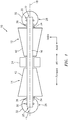
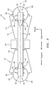
FIG. 3 illustrates a side, schematic view of a gas turbine engine, in accordance with one or more embodiments of the present disclosure. -
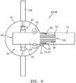
FIG. 4 illustrates a schematic view of an exemplary bearing compartment of the gas turbine engine ofFIG. 3 , in accordance with one or more embodiments of the present disclosure. -
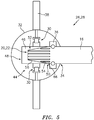
FIG. 5 illustrates a schematic view of an exemplary bearing compartment of the gas turbine engine ofFIG. 3 , in accordance with one or more embodiments of the present disclosure. -
FIG. 6 illustrates a schematic view of an exemplary bearing compartment of the gas turbine engine ofFIG. 3 , in accordance with one or more embodiments of the present disclosure. - It is noted that various connections are set forth between elements in the following description and in the drawings. It is noted that these connections are general and, unless specified otherwise, may be direct or indirect and that this specification is not intended to be limiting in this respect. A coupling between two or more entities may refer to a direct connection or an indirect connection. An indirect connection may incorporate one or more intervening entities. It is further noted that various method or process steps for embodiments of the present disclosure are described in the following description and drawings. The description may present the method and/or process steps as a particular sequence. However, to the extent that the method or process does not rely on the particular order of steps set forth herein, the method or process should not be limited to the particular sequence of steps described. As one of ordinary skill in the art would appreciate, other sequences of steps may be possible. Therefore, the particular order of the steps set forth in the description should not be construed as a limitation.
- Referring to
FIGS. 1 and3 , agas turbine engine 10 in accordance with one or more embodiments of the present disclosure is schematically illustrated. Although embodiments of the present disclosure are described herein with respect to thegas turbine engine 10, it should be understood that the present disclosure is also applicable to other types of rotating machines. Thegas turbine engine 10 generally includes aturbine 12 and acompressor 14 in rotational communication with theturbine 12 via ashaft 16 configured to rotate about alongitudinal centerline 18 of thegas turbine engine 10. Theshaft 10 includes a forwardaxial end 20 and an aftaxial end 22. Thecompressor 14 drives air along a core flow path for compression and communication into acombustor 24. The airflow along the core flow path is mixed and burned with fuel in thecombustor 24 and then expanded over theturbine 12. Theturbine 12 rotationally drives theshaft 16 in response to the expansion. Aspects of the present disclosure may be applicable, for example, to attritable gas turbine engines and auxiliary power units (APUs) for drones, missiles, or other aircraft. Further, aspects of the present disclosure may be applicable to other gas turbine engine configurations such as, for example, two-spool gas turbine engines. - The
gas turbine engine 10 includes one or more bearing compartments, for example, a forward bearingcompartment 26 and anaft bearing compartment 28, each including one ormore bearings 30 configured to rotatably support theshaft 16. Each of theforward bearing compartment 26 and theaft bearing compartment 28 may include acompartment casing 32 generally defining an exterior housing of thebearing compartment compartment casing 32 includes ashaft aperture 34 configured for passage of theshaft 16 therethrough. In various embodiments, the bearing compartments 26, 28 may include ashaft seal 36 mounted to thecompartment casing 32 about theshaft aperture 34 and configured to be in sealing communication with theshaft 16. In various other embodiments, theshaft seal 36 may be mounted to theshaft 16 and configured to be in sealing communication with thecompartment casing 32. Theforward bearing compartment 26 may be in contact with the forwardaxial end 20 of theshaft 16 such that the forward bearingcompartment 26 is in mechanical communication with the forwardaxial end 20 of theshaft 16 or the forwardaxial end 20 of theshaft 16 is disposed within the forward bearingcompartment 26. Similarly, theaft bearing compartment 28 may be in contact with the aftaxial end 22 of theshaft 16 such that theaft bearing compartment 28 is in mechanical communication with the aftaxial end 22 of theshaft 16 or the aftaxial end 22 of theshaft 16 is disposed within theaft bearing compartment 28. - The
compartment casings 32 of the respective bearing compartments 22, 24 may be mounted axially outside thecompressor 14 and theturbine 12. For example, thecompartment casing 32 of theforward bearing compartment 26 may be mounted axially forward of thecompressor 14 while thecompartment casing 32 of theaft bearing compartment 28 may be mounted axially aft of theturbine 12. In various embodiments, thecompartment casing 32 may include aflange 38 for mounting therespective bearing compartment flange 38 may be used to mount the forward bearingcompartment 26 to an axially exterior portion of thecompressor 14, for example, acompressor casing 40 of thecompressor 14. In various embodiments, theflange 38 may be used to mount theaft bearing compartment 28 to an axially exterior portion of theturbine 12, for example aturbine casing 42 of theturbine 12. In various other embodiments, the bearing compartments 26, 28 may be mounted to other static structures of thegas turbine engine 10 separate from theturbine 12 or thecompressor 14. In various embodiments, one or both of the bearing compartments 26, 28 may be detachably mounted such that the bearing compartments 26, 28 may be installed or removed without physical entry into theturbine 12 or thecompressor 14. - The
compartment casing 32 may define a housing for aninternal lubrication system 44 disposed within the bearing compartments 26, 28 and configured to provide cooling and lubrication to thebearings 30. The bearing compartments 26, 28 may be self-contained such that theinternal lubrication system 44 of therespective bearing compartment gas turbine engine 10 outside therespective bearing compartment internal lubrication system 44 of the bearing compartments 26, 28 may not be in fluid communication with any support systems such as oil supply, oil scavenge, fluid cooling, hydraulic damping, or any other fluid systems of thegas turbine engine 10. Accordingly, the bearing compartments 26, 28 may be installed or removed without consideration for any fluid system connections. - Referring to
FIGS. 1 and2 , in various embodiments, portions of theshaft 16 may be disposed within the bearing compartments 26, 28. As illustrated, the forwardaxial end 20 of theshaft 16 may be disposed inside the forward bearingcompartment 26 via theshaft aperture 34. Similarly, the aftaxial end 22 of theshaft 16 may be disposed inside theaft bearing compartment 28 via theshaft aperture 34. In various other embodiments, theshaft 16 may pass through the bearing compartments 26, 28 such that, for example, the forwardaxial end 20 of theshaft 16 may be disposed axially forward of theforward bearing compartment 26 and/or the aftaxial end 22 of theshaft 16 may be disposed axially aft of theaft bearing compartment 28. - Referring to
FIGS. 3-5 , in various embodiments, one or both of the bearing compartments 26, 28 may include astub shaft 46 rotatably supported by thebearings 30 and extending through theshaft aperture 34. Thestub shaft 46 may include afirst end 48 disposed inside thecompartment casing 32 and asecond end 50 opposite thefirst end 48. Thesecond end 50 of thestub shaft 46 may be in communication with the respectiveaxial end shaft 16. Accordingly, thestub shaft 46 may be rotationally fixed relative to theshaft 16 such that theshaft 16 is rotatably supported by thebearings 30 via thestub shaft 46. - In various embodiments, one or both of the axial ends 20, 22 of the
shaft 16 may include arecess 52 which retains thesecond end 50 of the stub shaft 46 (seeFIG. 4 ). Alternatively, for example, thesecond end 50 of thestub shaft 46 may include therecess 52 which retains the respectiveaxial end FIG. 5 ). As previously discussed, thestub shaft 46 may be rotationally fixed relative to theshaft 16. Accordingly, therecess 52 may have a shape that substantially corresponds to a counterpart shape of thesecond end 50 of thestub shaft 46. In various embodiments, thesecond end 50 of thestub shaft 46 may include atapered surface 54 configured to mate with a corresponding taperedsurface 56 of theshaft 16 within therecess 52. In various embodiments, one or both of thestub shaft 46 and theshaft 16 may further include asplined portion 66 to prevent relative rotation between theshaft 16 and thestub shaft 46. In various embodiments, thesplined portion 66 may be disposed on the taperedsurface - Referring to
FIG. 6 , in various embodiments, the axial ends 20, 22 of theshaft 16 may include a threadedportion 68 configured to receive afastener 70. Thefastener 70 may retain theshaft 16 in position with respect to thebearing 30. In various embodiments, thefastener 70 may be mounted to or may be integral with aninterior race 72 of thebearing 30. - Referring to
FIGS. 1-6 , in various embodiments, the bearing compartments 26, 28 may include one or more features for circulating lubricant and/or lubricating thebearings 30. For example, in various embodiments, thestub shaft 46 may include an impeller portion 58 disposed within thecompartment casing 32. The impeller portion 58 of thestub shaft 46 may function to circulate lubricant within theinternal lubrication system 44 and provide lubricant to thebearings 30. - In various embodiments, one or more of the bearing compartments 26, 28 may include a
compartment insulation 60 applied to at least a portion of one or both of aninterior surface 62 and anexterior surface 64 of the compartment casing 32 (see, e.g.,FIG. 2 ). Thecompartment insulation 60 may provide thermal isolation to theinternal lubrication system 44 from thegas turbine engine 10. - The
bearings 30 of the present disclosure may include any bearing configuration suitable for rotatably supporting theshaft 16 or thestub shaft 46. For example, in various embodiments, thebearings 30 may be configured as roller bearings (see, e.g.,FIGS. 4 and5 ). Alternatively, in various embodiments, thebearings 30 may be configured as ball bearings and/or thrust bearings (see, e.g.,FIG. 6 ). - In various embodiments, to provide lubrication and cooling of the
bearing 30, theinternal lubrication system 44 may use thecompartment casing 32 to provide cooling to the lubricant of theinternal lubrication system 44. Specifically, lubricant within theinternal lubrication system 44 may be cooled by external airflow passing over theexterior surface 64 of thecompartment casing 32. In various other embodiments, alternative methods of cooling and/or lubricating thebearings 30 may be used. For example, in various embodiments, thebearings 30 may be configured as grease-packed bearings. In various embodiments, for example, where the operational time of thegas turbine engine 10 is expected to be sufficiently short, a dry lubricant may be applied to thebearings 30 prior to operation. - The modular nature of the bearing compartments 26, 28, as disclosed herein, may allow for relatively quick installation and removal of bearing
compartments gas turbine engine 10 operations. In various embodiments, the modular bearing compartments 26, 28 may be replaced to utilize a bearing compartment having an appropriate operational capacity for a given mission (e.g., a duration, condition, or engine loading capacity). For example, abearing compartment bearing compartment gas turbine engine 10 to be stored independent of conditions which may generally be required for successful storage of conventional gas turbine engine bearings. In other words, preservation of the bearing compartments 26, 28 and associatedbearings 30 may not be required duringgas turbine engine 10 downtime because new bearing compartments 26, 28 can be quickly installed in thegas turbine engine 10 prior to an intended operation. For example, grease-packed bearings may be refreshed when the grease shelf life expires, without requiring significant overhaul to thegas turbine engine 10. - Additionally, the self-contained configuration of the bearing compartments 26, 28, according to embodiments of the present disclosure, may enable a reduction in a diameter/size of the
gas turbine engine 10 core, and an associated reduction in weight, as a result of the elimination of bearing support systems conventionally used for bearing compartments. - While various aspects of the present disclosure have been disclosed, it will be apparent to those of ordinary skill in the art that many more embodiments and implementations are possible within the scope of the present disclosure. For example, the present disclosure as described herein includes several aspects and embodiments that include particular features. Although these particular features may be described individually, it is within the scope of the present disclosure that some or all of these features may be combined with any one of the aspects and remain within the scope of the present disclosure. References to "various embodiments," "one embodiment," "an embodiment," "an example embodiment," etc., indicate that the embodiment described may include a particular feature, structure, or characteristic, but every embodiment may not necessarily include the particular feature, structure, or characteristic. Moreover, such phrases are not necessarily referring to the same embodiment. Further, when a particular feature, structure, or characteristic is described in connection with an embodiment, it is submitted that it is within the knowledge of one skilled in the art to effect such feature, structure, or characteristic in connection with other embodiments whether or not explicitly described. Accordingly, the present disclosure is not to be restricted except in light of the attached claims and their equivalents.
Claims (15)
- A gas turbine engine comprising:a turbine (12);a compressor (14) in rotational communication with the turbine (12) via a shaft (16), the shaft (16) rotatable about a longitudinal centerline (18) and comprising a first axial end (20, 22) and a second axial end (20, 22) opposite the first axial end (20, 22); anda first bearing compartment (26, 28) comprising a first compartment casing (32) detachably mounted axially outside the compressor (14) and the turbine (12), the first bearing compartment (26, 28) in contact with the first axial end (20, 22) of the shaft (16) and comprising a first bearing (30) which rotatably supports the shaft (16),wherein the first bearing compartment (26, 28) is self-contained such that an internal lubrication system (44) of the first bearing compartment (26, 28) is fluidally isolated from a remainder of the gas turbine engine outside the first bearing compartment (26, 28).
- The gas turbine engine of claim 1, wherein the first compartment casing (32) comprises a flange (38) for mounting the first bearing compartment (26, 28) to an axially exterior portion (40, 42) of the turbine or the compressor.
- The gas turbine engine of claim 1 or 2, wherein the first compartment casing (32) comprises a shaft aperture (34), configured for passage of the shaft (16) therethrough, and a shaft seal (36) mounted to the first compartment casing (32) about the shaft aperture (34) and configured to be in sealing communication with the shaft (16).
- The gas turbine engine of claim 1 or 2, wherein the first compartment casing (32) comprises a shaft aperture (34) and a shaft seal (36) mounted to the first compartment casing (32) about the shaft aperture (34), and wherein the first bearing compartment (26, 28) further comprises a stub shaft (46) extending through the shaft aperture (34), the stub shaft (46) comprising a first end (48) disposed inside the first compartment casing (32) and a second end (50) in communication with the first axial end (20, 22) of the shaft (16), the stub shaft (46) rotationally fixed relative to the shaft (16) and the shaft seal is in sealing communication with the stub shaft (46).
- The gas turbine engine of claim 4, wherein:the first axial end (20, 22) of the shaft (16) comprises a recess (52) which retains the second end (50) of the stub shaft (46); and/orthe second end (50) of the stub shaft (46) includes a tapered surface (54); and/orone or both of the stub shaft (46) and the shaft (16) further comprise a splined portion (66).
- The gas turbine engine of claim 1-2, wherein the first axial end (20, 22) of the shaft (16) is disposed inside the first bearing compartment (26, 28), and wherein, optionally, the first compartment casing (32) comprises a shaft aperture (34) through which the shaft (16) extends and a shaft seal (36) mounted to the shaft (16) and configured to be in sealing communication with the first compartment casing (32).
- The gas turbine engine of any preceding claim, wherein the first bearing compartment (26, 28) further comprises a compartment insulation (60) applied to at least a portion of one or both of an interior surface (62) and an exterior surface (64) of the first compartment casing (32).
- The gas turbine engine of any preceding claim, wherein the first bearing (30) is a grease-packed bearing.
- The gas turbine engine of any preceding claim, further comprising a second bearing compartment (26, 28) comprising a second compartment casing (32) detachably mounted axially outside the compressor (14) and the turbine (12), the second bearing compartment (26, 28) in contact with the second axial end (20, 22) of the shaft (16) and comprising a second bearing (30) which rotatably supports the shaft (16).
- A method for installing a bearing compartment in a gas turbine engine, the method comprising:providing a gas turbine engine (10) comprising a turbine (12) and a compressor (14) in rotational communication with the turbine (12) via a shaft (16), the shaft (16) rotatable about a longitudinal centerline (18) and comprising a first axial end (20, 22) and a second axial end (20, 22) opposite the first axial end (20, 22); andinstalling a bearing compartment (26, 28) in the gas turbine engine (10) by detachably mounting a compartment casing (32) of the bearing compartment (26,28) axially outside the compressor (14) and the turbine (16) such that the bearing compartment (26, 28) is in contact with the first axial end (20, 22) of the shaft (16) and a first bearing (30) of the bearing compartment (26, 28) rotatably supports the shaft (16).
- The method of claim 10, wherein the bearing compartment is a second bearing compartment (26, 28), the method further comprising removing a first bearing compartment (26, 28) prior to the step of installing the second bearing compartment (26, 28) in the gas turbine engine.
- The method of claim 11, wherein the second bearing compartment (26, 28) has a second operational capacity which is different than a first corresponding operational capacity of the first bearing compartment (26, 28).
- A bearing compartment system for a gas turbine engine, the bearing compartment system comprising:a shaft (16) rotatable about a longitudinal centerline (18) and comprising a first axial end (20, 22) and a second axial end (20, 22) opposite the first axial end (20, 22); anda bearing compartment (26, 28) comprising a compartment casing (32), the bearing compartment (26, 28) in contact with the first axial end (20, 22) of the shaft (16) and comprising a first bearing (30) which rotatably supports the shaft (16),wherein the bearing compartment (26, 28) is self-contained such that an internal lubrication system (44) of the bearing compartment is configured to be fluidally isolated from a remainder of a gas turbine engine (10) outside the bearing compartment (26,28).
- The method of any of claims 10-12 or the bearing compartment system of claim 13,
wherein the compartment casing (32) comprises a shaft aperture (34), and
wherein the bearing compartment (26, 28) further comprises a stub shaft (46) extending through the shaft aperture (34), the stub shaft (46) comprising a first end (48) disposed inside the compartment casing (32) and a second end (50) in communication with the first axial end (20, 22) of the shaft (16), the stub shaft (46) rotationally fixed relative to the shaft (16). - The method of any of claims 10-12 or 14 or the bearing compartment system of claim 13 or 14, wherein the first axial end (20, 22) of the shaft (16) is disposed inside the bearing compartment (26, 28).
Applications Claiming Priority (1)
| Application Number | Priority Date | Filing Date | Title |
|---|---|---|---|
| US16/818,593 US11333039B2 (en) | 2020-03-13 | 2020-03-13 | Modular bearing compartment |
Publications (2)
| Publication Number | Publication Date |
|---|---|
| EP3879080A1 true EP3879080A1 (en) | 2021-09-15 |
| EP3879080B1 EP3879080B1 (en) | 2025-10-29 |
Family
ID=74873613
Family Applications (1)
| Application Number | Title | Priority Date | Filing Date |
|---|---|---|---|
| EP21162350.9A Active EP3879080B1 (en) | 2020-03-13 | 2021-03-12 | Modular bearing component |
Country Status (2)
| Country | Link |
|---|---|
| US (1) | US11333039B2 (en) |
| EP (1) | EP3879080B1 (en) |
Citations (4)
| Publication number | Priority date | Publication date | Assignee | Title |
|---|---|---|---|---|
| WO1980002585A1 (en) * | 1979-05-14 | 1980-11-27 | Norbert L Osborn | Turbocharger and adaptations thereof |
| US6286303B1 (en) * | 1999-11-18 | 2001-09-11 | Allied Signal, Inc. | Impingement cooled foil bearings in a gas turbine engine |
| US20050132693A1 (en) * | 2003-12-22 | 2005-06-23 | Pratt & Whitney Canada Corp. | Gas turbine engine architecture |
| US20190360352A1 (en) * | 2016-09-13 | 2019-11-28 | Delta Motorsport Limited | Gas turbine generators |
Family Cites Families (4)
| Publication number | Priority date | Publication date | Assignee | Title |
|---|---|---|---|---|
| DE69730781T2 (en) | 1996-06-26 | 2005-09-29 | Rolls-Royce Corp., Indianapolis | Storage combination for a gas turbine |
| US6942451B1 (en) | 2003-06-03 | 2005-09-13 | Hamilton Sundstrand Corporation | Damping system for an expendable gas turbine engine |
| US8727699B2 (en) | 2009-12-29 | 2014-05-20 | Rolls-Royce Corporation | Rotating machinery with damping system |
| FR2964425B1 (en) | 2010-09-03 | 2014-02-14 | Snecma | TURBOPOMPE, ESPECIALLY FOR FEEDING ROTOR MOTORS |
-
2020
- 2020-03-13 US US16/818,593 patent/US11333039B2/en active Active
-
2021
- 2021-03-12 EP EP21162350.9A patent/EP3879080B1/en active Active
Patent Citations (4)
| Publication number | Priority date | Publication date | Assignee | Title |
|---|---|---|---|---|
| WO1980002585A1 (en) * | 1979-05-14 | 1980-11-27 | Norbert L Osborn | Turbocharger and adaptations thereof |
| US6286303B1 (en) * | 1999-11-18 | 2001-09-11 | Allied Signal, Inc. | Impingement cooled foil bearings in a gas turbine engine |
| US20050132693A1 (en) * | 2003-12-22 | 2005-06-23 | Pratt & Whitney Canada Corp. | Gas turbine engine architecture |
| US20190360352A1 (en) * | 2016-09-13 | 2019-11-28 | Delta Motorsport Limited | Gas turbine generators |
Also Published As
| Publication number | Publication date |
|---|---|
| EP3879080B1 (en) | 2025-10-29 |
| US11333039B2 (en) | 2022-05-17 |
| US20210285337A1 (en) | 2021-09-16 |
Similar Documents
| Publication | Publication Date | Title |
|---|---|---|
| US7510369B2 (en) | Sacrificial inner shroud liners for gas turbine engines | |
| US8011884B1 (en) | Fan blade assembly for a gas turbine engine | |
| US5921683A (en) | Bearing arrangement for air cycle machine | |
| EP0547279B1 (en) | Bearing cooling arrangement for air cycle machine | |
| US9841056B2 (en) | Bearing with drained race and squeeze film damper | |
| USRE36101E (en) | Air cycle machine with magnetic bearings | |
| US8904746B2 (en) | Method and apparatus for segregated oil supply and scavenge in a gas turbine engine | |
| US10196986B2 (en) | Hydrodynamic seals in bearing compartments of gas turbine engines | |
| US12152538B2 (en) | Turbomachine comprising a rear integrated electrical machine | |
| US10392969B2 (en) | Moment accommodating fastener assembly | |
| US20120011824A1 (en) | Integral lubrication tube and nozzle combination | |
| US10830092B2 (en) | Bearing rotor thrust control | |
| US11143045B2 (en) | Intermediate case for an aircraft turbomachine made from a single casting with a lubricant duct | |
| EP3513043B1 (en) | A radial flow gas turbine generator | |
| EP3239545B1 (en) | Integrated oil supply tube and check valve | |
| EP3879080B1 (en) | Modular bearing component | |
| US9352649B2 (en) | Accessory relay having an extended service life | |
| GB2613246A (en) | Lubrication system for turbine engine electric machine | |
| US2779531A (en) | Gas turbine engine with hydraulic thrust balancing | |
| US12163432B2 (en) | Self-guiding carbon seal system | |
| US11746699B2 (en) | Gas turbine engine | |
| US12203382B1 (en) | Bearing oil distribution scheme | |
| US12203413B1 (en) | Bearing configuration for a rotational equipment assembly | |
| US12492649B2 (en) | Lubrication system and methods of lubricating a gearbox assembly | |
| US20160298472A1 (en) | Shim to maintain gap during engine assembly |
Legal Events
| Date | Code | Title | Description |
|---|---|---|---|
| PUAI | Public reference made under article 153(3) epc to a published international application that has entered the european phase |
Free format text: ORIGINAL CODE: 0009012 |
|
| STAA | Information on the status of an ep patent application or granted ep patent |
Free format text: STATUS: THE APPLICATION HAS BEEN PUBLISHED |
|
| AK | Designated contracting states |
Kind code of ref document: A1 Designated state(s): AL AT BE BG CH CY CZ DE DK EE ES FI FR GB GR HR HU IE IS IT LI LT LU LV MC MK MT NL NO PL PT RO RS SE SI SK SM TR |
|
| STAA | Information on the status of an ep patent application or granted ep patent |
Free format text: STATUS: REQUEST FOR EXAMINATION WAS MADE |
|
| 17P | Request for examination filed |
Effective date: 20220315 |
|
| RBV | Designated contracting states (corrected) |
Designated state(s): AL AT BE BG CH CY CZ DE DK EE ES FI FR GB GR HR HU IE IS IT LI LT LU LV MC MK MT NL NO PL PT RO RS SE SI SK SM TR |
|
| STAA | Information on the status of an ep patent application or granted ep patent |
Free format text: STATUS: EXAMINATION IS IN PROGRESS |
|
| RAP3 | Party data changed (applicant data changed or rights of an application transferred) |
Owner name: RTX CORPORATION |
|
| 17Q | First examination report despatched |
Effective date: 20231017 |
|
| GRAP | Despatch of communication of intention to grant a patent |
Free format text: ORIGINAL CODE: EPIDOSNIGR1 |
|
| STAA | Information on the status of an ep patent application or granted ep patent |
Free format text: STATUS: GRANT OF PATENT IS INTENDED |
|
| INTG | Intention to grant announced |
Effective date: 20250528 |
|
| GRAS | Grant fee paid |
Free format text: ORIGINAL CODE: EPIDOSNIGR3 |
|
| GRAA | (expected) grant |
Free format text: ORIGINAL CODE: 0009210 |
|
| STAA | Information on the status of an ep patent application or granted ep patent |
Free format text: STATUS: THE PATENT HAS BEEN GRANTED |
|
| AK | Designated contracting states |
Kind code of ref document: B1 Designated state(s): AL AT BE BG CH CY CZ DE DK EE ES FI FR GB GR HR HU IE IS IT LI LT LU LV MC MK MT NL NO PL PT RO RS SE SI SK SM TR |
|
| REG | Reference to a national code |
Ref country code: CH Ref legal event code: F10 Free format text: ST27 STATUS EVENT CODE: U-0-0-F10-F00 (AS PROVIDED BY THE NATIONAL OFFICE) Effective date: 20251029 Ref country code: GB Ref legal event code: FG4D |
|
| REG | Reference to a national code |
Ref country code: IE Ref legal event code: FG4D |
|
| REG | Reference to a national code |
Ref country code: DE Ref legal event code: R096 Ref document number: 602021041117 Country of ref document: DE |
|
| REG | Reference to a national code |
Ref country code: NL Ref legal event code: MP Effective date: 20251029 |
|
| PGFP | Annual fee paid to national office [announced via postgrant information from national office to epo] |
Ref country code: GB Payment date: 20260220 Year of fee payment: 6 |
|
| PG25 | Lapsed in a contracting state [announced via postgrant information from national office to epo] |
Ref country code: ES Free format text: LAPSE BECAUSE OF FAILURE TO SUBMIT A TRANSLATION OF THE DESCRIPTION OR TO PAY THE FEE WITHIN THE PRESCRIBED TIME-LIMIT Effective date: 20251029 |
|
| REG | Reference to a national code |
Ref country code: LT Ref legal event code: MG9D |
|
| PG25 | Lapsed in a contracting state [announced via postgrant information from national office to epo] |
Ref country code: NO Free format text: LAPSE BECAUSE OF FAILURE TO SUBMIT A TRANSLATION OF THE DESCRIPTION OR TO PAY THE FEE WITHIN THE PRESCRIBED TIME-LIMIT Effective date: 20260129 |
|
| PGFP | Annual fee paid to national office [announced via postgrant information from national office to epo] |
Ref country code: DE Payment date: 20260219 Year of fee payment: 6 |
|
| PG25 | Lapsed in a contracting state [announced via postgrant information from national office to epo] |
Ref country code: HR Free format text: LAPSE BECAUSE OF FAILURE TO SUBMIT A TRANSLATION OF THE DESCRIPTION OR TO PAY THE FEE WITHIN THE PRESCRIBED TIME-LIMIT Effective date: 20251029 Ref country code: AT Free format text: LAPSE BECAUSE OF FAILURE TO SUBMIT A TRANSLATION OF THE DESCRIPTION OR TO PAY THE FEE WITHIN THE PRESCRIBED TIME-LIMIT Effective date: 20251029 Ref country code: FI Free format text: LAPSE BECAUSE OF FAILURE TO SUBMIT A TRANSLATION OF THE DESCRIPTION OR TO PAY THE FEE WITHIN THE PRESCRIBED TIME-LIMIT Effective date: 20251029 |
|
| REG | Reference to a national code |
Ref country code: AT Ref legal event code: MK05 Ref document number: 1851774 Country of ref document: AT Kind code of ref document: T Effective date: 20251029 |
|
| PG25 | Lapsed in a contracting state [announced via postgrant information from national office to epo] |
Ref country code: NL Free format text: LAPSE BECAUSE OF FAILURE TO SUBMIT A TRANSLATION OF THE DESCRIPTION OR TO PAY THE FEE WITHIN THE PRESCRIBED TIME-LIMIT Effective date: 20251029 |
|
| PG25 | Lapsed in a contracting state [announced via postgrant information from national office to epo] |
Ref country code: RS Free format text: LAPSE BECAUSE OF FAILURE TO SUBMIT A TRANSLATION OF THE DESCRIPTION OR TO PAY THE FEE WITHIN THE PRESCRIBED TIME-LIMIT Effective date: 20260129 |
|
| PG25 | Lapsed in a contracting state [announced via postgrant information from national office to epo] |
Ref country code: IS Free format text: LAPSE BECAUSE OF FAILURE TO SUBMIT A TRANSLATION OF THE DESCRIPTION OR TO PAY THE FEE WITHIN THE PRESCRIBED TIME-LIMIT Effective date: 20260228 |
|
| PGFP | Annual fee paid to national office [announced via postgrant information from national office to epo] |
Ref country code: FR Payment date: 20260219 Year of fee payment: 6 |
|
| PG25 | Lapsed in a contracting state [announced via postgrant information from national office to epo] |
Ref country code: PT Free format text: LAPSE BECAUSE OF FAILURE TO SUBMIT A TRANSLATION OF THE DESCRIPTION OR TO PAY THE FEE WITHIN THE PRESCRIBED TIME-LIMIT Effective date: 20260302 |
|
| PG25 | Lapsed in a contracting state [announced via postgrant information from national office to epo] |
Ref country code: PL Free format text: LAPSE BECAUSE OF FAILURE TO SUBMIT A TRANSLATION OF THE DESCRIPTION OR TO PAY THE FEE WITHIN THE PRESCRIBED TIME-LIMIT Effective date: 20251029 |
|
| PG25 | Lapsed in a contracting state [announced via postgrant information from national office to epo] |
Ref country code: LV Free format text: LAPSE BECAUSE OF FAILURE TO SUBMIT A TRANSLATION OF THE DESCRIPTION OR TO PAY THE FEE WITHIN THE PRESCRIBED TIME-LIMIT Effective date: 20251029 |
|
| PG25 | Lapsed in a contracting state [announced via postgrant information from national office to epo] |
Ref country code: BG Free format text: LAPSE BECAUSE OF FAILURE TO SUBMIT A TRANSLATION OF THE DESCRIPTION OR TO PAY THE FEE WITHIN THE PRESCRIBED TIME-LIMIT Effective date: 20251029 |