EP3879068A1 - Downhole line separation tool - Google Patents
Downhole line separation tool Download PDFInfo
- Publication number
- EP3879068A1 EP3879068A1 EP20162497.0A EP20162497A EP3879068A1 EP 3879068 A1 EP3879068 A1 EP 3879068A1 EP 20162497 A EP20162497 A EP 20162497A EP 3879068 A1 EP3879068 A1 EP 3879068A1
- Authority
- EP
- European Patent Office
- Prior art keywords
- tool
- housing part
- downhole
- annular
- casing
- Prior art date
- Legal status (The legal status is an assumption and is not a legal conclusion. Google has not performed a legal analysis and makes no representation as to the accuracy of the status listed.)
- Withdrawn
Links
Images



Classifications
-
- E—FIXED CONSTRUCTIONS
- E21—EARTH OR ROCK DRILLING; MINING
- E21B—EARTH OR ROCK DRILLING; OBTAINING OIL, GAS, WATER, SOLUBLE OR MELTABLE MATERIALS OR A SLURRY OF MINERALS FROM WELLS
- E21B29/00—Cutting or destroying pipes, packers, plugs or wire lines, located in boreholes or wells, e.g. cutting of damaged pipes, of windows; Deforming of pipes in boreholes or wells; Reconditioning of well casings while in the ground
- E21B29/04—Cutting of wire lines or the like
-
- E—FIXED CONSTRUCTIONS
- E21—EARTH OR ROCK DRILLING; MINING
- E21B—EARTH OR ROCK DRILLING; OBTAINING OIL, GAS, WATER, SOLUBLE OR MELTABLE MATERIALS OR A SLURRY OF MINERALS FROM WELLS
- E21B23/00—Apparatus for displacing, setting, locking, releasing or removing tools, packers or the like in boreholes or wells
- E21B23/14—Apparatus for displacing, setting, locking, releasing or removing tools, packers or the like in boreholes or wells for displacing a cable or a cable-operated tool, e.g. for logging or perforating operations in deviated wells
Definitions
- the present invention relates to a downhole line separation tool for submerging into a casing in a wellbore, the downhole line separation tool having a first tool end, a second tool end and a tool axis. Moreover, the present invention also relates to a downhole system comprising an upper casing connected to a lower casing and arranged in the wellbore.
- control lines are installed running on the outside of the upper casing in order to control valves for adjusting inflow of oil or gas into the completion or closing the flow upwards inside the casing.
- the control lines are pulled out with the upper casing and often the lines break so that the lines enter the inside of the lower casing.
- the control lines are squeezed in between the upper and lower casing.
- Some upper casings are installed with a control line cutter which is mounted as part and on the outer face of the upper casing and thus retracted with the upper casing. However, if the control line cutter fails or the upper casing does not have such control line cutter, the operator has no other alternative than to pull out the upper casing with the risk of the control lines falling into the inside of the lower casing.
- a downhole line separation tool for submerging into a casing in a wellbore, the downhole line separation tool having a first tool end, a second tool end and a tool axis, comprising:
- the projecting part By having a projecting part extending beyond the annular separation element, the projecting part abuts the edge in the casing providing the possibility of the annular separation element rotating for cutting and separating one part of the line from a remaining part of the line without harming the casing, e.g. by machining in the casing.
- the projecting part may have a width from the element end further along the tool axis away from the first tool end, the width being more than 0.3mm and less than 20mm.
- the projecting part may have a radial extension from an inner diameter of the second housing part and radially inwards, the radial extension being more than a thickness of the annular separation element.
- the annular separation element may comprise several bits arranged at the element end and along a circumference of the annular separation element.
- the several bits may form an edge for abutment to and cutting into a line in a casing.
- the annular separation element may comprise an annular grinding bit having abrasive particles arranged in the element end forming an edge for abutment to and cutting into a line in a casing.
- the downhole line separation tool may further comprise a pump arranged between the first tool end and the second housing part and having a pump inlet in fluid communication with an inside of the annular separation element though an inside of the second housing part, and the pump having a pump outlet in the tool housing so that the pump sucks fluid in through the annular separation element though the inside of the second housing part and out through the outlet.
- the downhole line separation tool may further comprise an accumulation section arranged between the element end of the annular separation element and the pump.
- the accumulation section may comprise an accumulation housing enclosing an accumulation chamber in which a filtering element is arranged, and the accumulation section is arranged between the element end of the annular separation element and the pump so that fluid is sucked in through the annular separation element into the accumulation chamber and further in through the filtering element and in through the pump inlet.
- the accumulation housing may form part of the tool housing.
- the downhole line separation may further comprise a gearing section connected between the electrical motor and the rotatable shaft for reducing the rotation of the annular separation element in relation to the rotational output of the motor.
- the downhole line separation tool may further comprise an anchoring tool section for preventing the tool from rotating within the casing.
- anchoring tool section may comprise projectable anchoring elements.
- the downhole line separation tool may further comprise an axial force generator providing an axial force along the tool axis.
- the downhole line separation tool may further comprise a driving unit, such as a downhole tractor, for preventing the tool from rotating within the casing and for providing an axial force along the tool axis.
- a driving unit such as a downhole tractor
- the downhole line separation tool may be a wireline tool.
- the driving unit may comprise a second motor driving a second pump for rotating wheels and projecting arms onto which the wheels are arranged.
- the downhole line separation tool may comprise a compensator for providing a surplus pressure inside the downhole line separation tool.
- the annular separation element may have at least one cutting bit forming the element end.
- the tool housing having the first housing part and the second housing part may be stationary.
- the second housing part may have a larger outer diameter than an outer diameter of the first housing part.
- the present invention also relates to a downhole system comprising an upper casing connected to a lower casing and arranged in the wellbore, and the lower casing having an inner diameter being smaller than an inner diameter of the upper casing providing a circumferential edge of the lower casing, the downhole system further comprises a downhole line separation tool, wherein the projecting part abutting the circumferential edge of the lower casing.
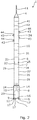
- Fig. 1 shows a downhole line separation tool 1 for submerging into a casing 2 (shown in Fig. 4 ) in a wellbore 3 (shown in Fig. 4 ).
- the downhole line separation tool has a first tool end 4 nearest a top 51 (illustrated by an arrow in Fig. 1 ) of the well, a second tool end 5 furthest away from the top of the well and a tool axis L.
- the downhole line separation tool comprises a tool housing 6 having a first housing part 7 and a second housing part 8.
- the downhole line separation tool further comprises an electrical motor 10 arranged within the first housing part and powered through a wireline 11 connected to the first tool end.
- the downhole line separation tool is a wireline tool and is an intervention tool for intervening a well.
- the downhole line separation tool comprises an annular separation element 9 having an element end 12 facing away from the first tool end and being rotatably connected within the second housing part by means of a rotatable shaft 14 arranged within the second housing part and rotated by the electrical motor for rotating the annular separation element 9.
- the second housing part comprises a sleeve part 15 having a sleeve end 16. As can be seen, part of the annular separation element 9 projects from the sleeve end 16 and projects further away from the first tool end than the sleeve.
- the second housing part also comprises a projecting part 17 extending further away from the first tool end than the annular cutting element along the tool axis L.
- the annular separation element 9 is exposed for cutting or grinding into the control line 20 (shown in Fig. 4 ) except when passing the projecting part 17 when rotating underneath the projecting part.
- the tool housing 6 having the first housing part 7 and the second housing part 8 is stationary while the annular separation element 9 is rotating.
- the projecting part 17 abuts a circumferential edge 46 of the lower casing resulting from an upper casing 2a connected to the lower casing 2b where the lower casing has an inner diameter ID3 being smaller than an inner diameter ID4 of the lower casing providing the circumferential edge 46 of the lower casing.
- a control line 20 or other type of line has fallen into the casing and is squeezed in between the upper casing and the lower casing.
- the bits 18A of annular separation element 9 cut or grind into the control line, separating the part of the control line extending into the casing from the remaining part. Having a control line floating within the casing can among other things prohibit the upper casing being properly installed resulting in a leak and/or that intervention tools can operate in the well.
- the projecting part 17 is stationary abutting the edge in the casing providing the possibility of the annular separation element 9 rotating for cutting and separating one part of the line from a remaining part of the line without harming, the casing, e.g. by machining in the casing.
- the projecting part has a width w from the element end further along the tool axis away from the first tool end.
- the width may be more than 0.3mm and less than 20mm.
- Control lines often have an outer diameter of more than 0.3mm and less than 20mm, and the width of the projecting part is designed to correspond to the outer diameter of the control line to be cut or grinded.
- the projecting part has a radial extension R from an inner diameter ID1 of the second housing part and radially inwards.
- the radial extension may be more than a thickness t of the annular separation element.
- the annular separation element 9 comprises several bits 18A arranged at the element end 12 and along a circumference of the annular separation element 9.
- the several bits 18A form an edge 19 abutting and cutting into the line 20 in the casing 2.
- the annular separation element may thus be formed of several bits or inserts forming the edge abutting and cutting into the line 20 in the casing 2.
- the annular separation element 9 comprises an annular grinding bit 18B having abrasive particles, the annular grinding bit being arranged in the element end 12 forming an edge 19 abutting and grinding into the line 20 in the casing.
- the annular grinding bit 18A may in another embodiment be comprised of several grinding bits when mounted closely together along the circumference of the annular separation element form a common annular grinding bit.
- the downhole line separation tool 1 comprising a pump 21 arranged between the first tool end 4 and the second housing part 8.
- the pump 21 has a pump inlet 22 in fluid communication with an inside 23 of the annular separation element 9 though an inside 24 of the second housing part 8.
- the pump 21 has a pump outlet 25 in the wall of the tool housing 6 so that the pump sucks fluid in through the annular separation element 9 though the inside of the second housing part and out through the outlet.
- the downhole line separation tool 1 further comprises an accumulation section 26 arranged between the element end 12 of the annular separation element 9 and the pump 21. As indicated by dotted lines, the accumulation section 26 comprises an accumulation housing 27 enclosing an accumulation chamber 28 in which a filtering element 29 is arranged.
- the accumulation section 26 is arranged between the element end 12 of the annular separation element 9 and the pump 21 so that well fluid is sucked in through the annular separation element 9 into the accumulation chamber 28 and further in through the filtering element 29 and in through the pump inlet 22.
- the accumulation housing 27 forms part of the tool housing 6.
- the downhole line separation tool 1 may further comprise a gearing section 31 as shown in Fig. 1 .
- the gearing section 31 is connected between the electrical motor 10 and the rotatable shaft 14 for reducing the rotation of the annular separation element 9 in relation to the rotational output of the motor 10.
- the downhole line separation tool 1 further comprises a driving unit 34, such as a downhole tractor, for preventing the tool from rotating within the casing and for providing an axial force along the tool axis.
- the downhole line separation tool further comprises a compensator 45 for providing a surplus pressure inside the downhole line separation tool.
- the driving unit comprises a second motor 41 driving a second pump 42 for rotating wheels 43 and projecting arms 44 onto which the wheels are arranged.
- the downhole line separation tool 1 comprises an anchoring tool section 32 for preventing the tool from rotating within the casing.
- the anchoring tool section comprises projectable anchoring elements 47 projectable for abutting an inner face of the casing.
- the downhole line separation tool 1 further comprises an axial force generator 33 providing an axial force along the tool axis so that the annular separation element 9 is forced towards the control line and the circumferential edge 46 (shown in Figs. 4 and 5 ).
- the projecting part 17 has an inclined outer end face 49 so that the projecting parts can align the tool in the casing as shown in Fig. 4 . Furthermore, by having such inclined outer end face 49, the projecting part 17 can also better fit into place on top of the circumferential edge 46 of the lower casing 2b.
- annular separation element 9 projects from a sleeve end face 16B of the sleeve end 16 and projects further away from the first tool end than the sleeve creating a distance d from the element end 12 to a sleeve end face 16B.
- the annular separation element 9 is free to separate the control line 20 into one or more pieces by cutting or grinding or other types of machining processes. These pieces may be sucked into the accumulation section 26 by means of the pump 21, shown in Fig. 2 .
- the well fluid carries the pieces into the accumulation chamber 28 and is sucked further in through the filtering element 29 leaving the pieces in the annular cavity between the accumulation chamber 28 and the filtering element 29.
- the pieces are accumulated in the accumulation section 26 and are brought to surface when retracting the tool from the well after end of operation.
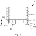
- the annular separation element 9 has at least one cutting bit 35 forming the element end 12 and in Fig. 6 , the annular separation element 9 has two cutting bits 35.
- the second housing part 8 has a larger outer diameter OD1 than an outer diameter OD2 of the first housing part 7.
- the second housing part can abut a lower casing having a smaller inner diameter while the smaller outer diameter of the first housing part provides room for e.g. wheels of the driving unit or anchoring elements of an anchoring section.
- the invention also relates to a downhole system 100 as partly shown in Figs. 4 and 5 .
- the downhole system 100 comprises an upper casing 2a connected to a lower casing 2b and arranged in the wellbore 3.
- the lower casing 2b has an inner diameter ID3 which is smaller than an inner diameter ID4 of the upper casing 2b providing a circumferential edge 46 of the lower casing.
- the downhole system 100 further comprises the abovementioned downhole line separation tool 1, wherein the projecting part 17 abuts the circumferential edge 46 of the lower casing 2b.
- An axial force generator may be a stroking tool and is a tool providing an axial force.
- the stroking tool comprises an electrical motor for driving a pump.
- the pump pumps fluid into a piston housing to move a piston acting therein.
- the piston is arranged on the stroker shaft.
- the pump may pump fluid into the piston housing on one side and simultaneously suck fluid out on the other side of the piston.
- fluid or well fluid any kind of fluid that may be present in oil or gas wells downhole, such as natural gas, oil, oil mud, crude oil, water, etc.
- gas is meant any kind of gas composition present in a well, completion, or open hole
- oil is meant any kind of oil composition, such as crude oil, an oil-containing fluid, etc.
- Gas, oil, and water fluids may thus all comprise other elements or substances than gas, oil, and/or water, respectively.
- a casing or well tubular metal structure is meant any kind of pipe, tubing, tubular, liner, string etc. used downhole in relation to oil or natural gas production.
- a downhole tractor can be used to push the tool all the way into position in the well.
- the downhole tractor may have projectable arms having wheels, wherein the wheels contact the inner surface of the casing for propelling the tractor and the tool forward in the casing.
- a downhole tractor is any kind of driving tool capable of pushing or pulling tools in a well downhole, such as a Well Tractor®.
Landscapes
- Life Sciences & Earth Sciences (AREA)
- Engineering & Computer Science (AREA)
- Geology (AREA)
- Mining & Mineral Resources (AREA)
- Physics & Mathematics (AREA)
- Environmental & Geological Engineering (AREA)
- Fluid Mechanics (AREA)
- General Life Sciences & Earth Sciences (AREA)
- Geochemistry & Mineralogy (AREA)
- Earth Drilling (AREA)
- Laying Of Electric Cables Or Lines Outside (AREA)
Abstract
The present invention relates to a downhole line separation tool for submerging into a casing in a wellbore, the downhole line separation tool having a first tool end, a second tool end and a tool axis, comprising a tool housing having a first housing part and a second housing part an electrical motor arranged within the first housing part and powered through a wireline connected to the first tool end, an annular separation element having an element end facing away from the first tool end and being rotatably connected within the second housing part, and a rotatable shaft arranged within the second housing part and rotated by the electrical motor for rotating the annular separation element, wherein the second housing part comprises a sleeve part having a sleeve end, at least part of the annular separation element projecting from the sleeve end further away from the first tool end than the sleeve, the second housing part comprising at least one projecting part extending further away from the first tool end than the annular cutting element along the tool axis. Moreover, the present invention also relates to a downhole system comprising an upper casing connected to a lower casing and arranged in the wellbore.
Description
- The present invention relates to a downhole line separation tool for submerging into a casing in a wellbore, the downhole line separation tool having a first tool end, a second tool end and a tool axis. Moreover, the present invention also relates to a downhole system comprising an upper casing connected to a lower casing and arranged in the wellbore.
- In oil and gas wells, control lines are installed running on the outside of the upper casing in order to control valves for adjusting inflow of oil or gas into the completion or closing the flow upwards inside the casing. When replacing the upper casing, the control lines are pulled out with the upper casing and often the lines break so that the lines enter the inside of the lower casing. As the new upper casing is installed, the control lines are squeezed in between the upper and lower casing.
- Some upper casings are installed with a control line cutter which is mounted as part and on the outer face of the upper casing and thus retracted with the upper casing. However, if the control line cutter fails or the upper casing does not have such control line cutter, the operator has no other alternative than to pull out the upper casing with the risk of the control lines falling into the inside of the lower casing.
- It is an object of the present invention to wholly or partly overcome the above disadvantages and drawbacks of the prior art. More specifically, it is an object to provide an improved downhole tool for separation and/or removing a stuck line in the casing.
- The above objects, together with numerous other objects, advantages and features, which will become evident from the below description, are accomplished by a solution in accordance with the present invention by a downhole line separation tool for submerging into a casing in a wellbore, the downhole line separation tool having a first tool end, a second tool end and a tool axis, comprising:
- a tool housing having a first housing part and a second housing part,
- an electrical motor arranged within the first housing part and powered through a wireline connected to the first tool end,
- an annular separation element having an element end facing away from the first tool end and being rotatably connected within the second housing part, and
- a rotatable shaft arranged within the second housing part and rotated by the electrical motor for rotating the annular separation element,
- By having a projecting part extending beyond the annular separation element, the projecting part abuts the edge in the casing providing the possibility of the annular separation element rotating for cutting and separating one part of the line from a remaining part of the line without harming the casing, e.g. by machining in the casing.
- In addition, the projecting part may have a width from the element end further along the tool axis away from the first tool end, the width being more than 0.3mm and less than 20mm.
- Furthermore, the projecting part may have a radial extension from an inner diameter of the second housing part and radially inwards, the radial extension being more than a thickness of the annular separation element.
- Also, the annular separation element may comprise several bits arranged at the element end and along a circumference of the annular separation element.
- Additionally, the several bits may form an edge for abutment to and cutting into a line in a casing.
- Further, the annular separation element may comprise an annular grinding bit having abrasive particles arranged in the element end forming an edge for abutment to and cutting into a line in a casing.
- Moreover, the downhole line separation tool may further comprise a pump arranged between the first tool end and the second housing part and having a pump inlet in fluid communication with an inside of the annular separation element though an inside of the second housing part, and the pump having a pump outlet in the tool housing so that the pump sucks fluid in through the annular separation element though the inside of the second housing part and out through the outlet.
- In addition, the downhole line separation tool may further comprise an accumulation section arranged between the element end of the annular separation element and the pump.
- Furthermore, the accumulation section may comprise an accumulation housing enclosing an accumulation chamber in which a filtering element is arranged, and the accumulation section is arranged between the element end of the annular separation element and the pump so that fluid is sucked in through the annular separation element into the accumulation chamber and further in through the filtering element and in through the pump inlet.
- Also, the accumulation housing may form part of the tool housing.
- Additionally, the downhole line separation may further comprise a gearing section connected between the electrical motor and the rotatable shaft for reducing the rotation of the annular separation element in relation to the rotational output of the motor.
- Moreover, the downhole line separation tool may further comprise an anchoring tool section for preventing the tool from rotating within the casing.
- Further, the anchoring tool section may comprise projectable anchoring elements.
- In addition, the downhole line separation tool may further comprise an axial force generator providing an axial force along the tool axis.
- Also, the downhole line separation tool may further comprise a driving unit, such as a downhole tractor, for preventing the tool from rotating within the casing and for providing an axial force along the tool axis.
- Furthermore, the downhole line separation tool may be a wireline tool.
- Additionally, the driving unit may comprise a second motor driving a second pump for rotating wheels and projecting arms onto which the wheels are arranged. Moreover, the downhole line separation tool may comprise a compensator for providing a surplus pressure inside the downhole line separation tool.
- In addition, the annular separation element may have at least one cutting bit forming the element end.
- Further, the tool housing having the first housing part and the second housing part may be stationary.
- Also, the second housing part may have a larger outer diameter than an outer diameter of the first housing part.
- Finally, the present invention also relates to a downhole system comprising an upper casing connected to a lower casing and arranged in the wellbore, and the lower casing having an inner diameter being smaller than an inner diameter of the upper casing providing a circumferential edge of the lower casing, the downhole system further comprises a downhole line separation tool, wherein the projecting part abutting the circumferential edge of the lower casing.
- The invention and its many advantages will be described in more detail below with reference to the accompanying schematic drawings, which for the purpose of illustration show some non-limiting embodiments and in which:
-
Fig. 1 shows a downhole line separation tool for cutting a line lost within a casing, -
Fig. 2 shows another downhole line separation tool, -
Fig. 3 shows yet another downhole line separation tool, -
Fig. 4 shows a partial cross-sectional view of part of the downhole line separation tool having an annular separation element when separation a part of a control line from another part of the control line on the outside of the casing, -
Fig. 5 shows a partial cross-sectional view of part of another downhole line separation tool, and -
Fig. 6 shows a partial cross-sectional view of part of yet another downhole line separation tool. - All the figures are highly schematic and not necessarily to scale, and they show only those parts which are necessary in order to elucidate the invention, other parts being omitted or merely suggested.
-
Fig. 1 shows a downholeline separation tool 1 for submerging into a casing 2 (shown inFig. 4 ) in a wellbore 3 (shown inFig. 4 ). The downhole line separation tool has afirst tool end 4 nearest a top 51 (illustrated by an arrow inFig. 1 ) of the well, a second tool end 5 furthest away from the top of the well and a tool axis L. The downhole line separation tool comprises atool housing 6 having afirst housing part 7 and asecond housing part 8. The downhole line separation tool further comprises anelectrical motor 10 arranged within the first housing part and powered through awireline 11 connected to the first tool end. Thus, the downhole line separation tool is a wireline tool and is an intervention tool for intervening a well. In the second tool end, the downhole line separation tool comprises anannular separation element 9 having anelement end 12 facing away from the first tool end and being rotatably connected within the second housing part by means of arotatable shaft 14 arranged within the second housing part and rotated by the electrical motor for rotating theannular separation element 9. The second housing part comprises asleeve part 15 having asleeve end 16. As can be seen, part of theannular separation element 9 projects from thesleeve end 16 and projects further away from the first tool end than the sleeve. The second housing part also comprises a projectingpart 17 extending further away from the first tool end than the annular cutting element along the tool axis L. In this way, theannular separation element 9 is exposed for cutting or grinding into the control line 20 (shown inFig. 4 ) except when passing the projectingpart 17 when rotating underneath the projecting part. Thetool housing 6 having thefirst housing part 7 and thesecond housing part 8 is stationary while theannular separation element 9 is rotating. - As shown in
Fig. 4 , the projectingpart 17 abuts acircumferential edge 46 of the lower casing resulting from anupper casing 2a connected to thelower casing 2b where the lower casing has an inner diameter ID3 being smaller than an inner diameter ID4 of the lower casing providing thecircumferential edge 46 of the lower casing. When inserting the upper casing, acontrol line 20 or other type of line has fallen into the casing and is squeezed in between the upper casing and the lower casing. Thebits 18A ofannular separation element 9 cut or grind into the control line, separating the part of the control line extending into the casing from the remaining part. Having a control line floating within the casing can among other things prohibit the upper casing being properly installed resulting in a leak and/or that intervention tools can operate in the well. - Thus, by having a projecting
part 17 extending beyond theannular separation element 9, the projectingpart 17 is stationary abutting the edge in the casing providing the possibility of theannular separation element 9 rotating for cutting and separating one part of the line from a remaining part of the line without harming, the casing, e.g. by machining in the casing. - As shown in
Fig. 4 , the projecting part has a width w from the element end further along the tool axis away from the first tool end. The width may be more than 0.3mm and less than 20mm. Control lines often have an outer diameter of more than 0.3mm and less than 20mm, and the width of the projecting part is designed to correspond to the outer diameter of the control line to be cut or grinded. The projecting part has a radial extension R from an inner diameter ID1 of the second housing part and radially inwards. The radial extension may be more than a thickness t of the annular separation element. - In
Fig. 4 , theannular separation element 9 comprisesseveral bits 18A arranged at theelement end 12 and along a circumference of theannular separation element 9. Theseveral bits 18A form anedge 19 abutting and cutting into theline 20 in thecasing 2. The annular separation element may thus be formed of several bits or inserts forming the edge abutting and cutting into theline 20 in thecasing 2. - In
Fig. 5 , theannular separation element 9 comprises an annulargrinding bit 18B having abrasive particles, the annular grinding bit being arranged in theelement end 12 forming anedge 19 abutting and grinding into theline 20 in the casing. The annular grinding bit 18A may in another embodiment be comprised of several grinding bits when mounted closely together along the circumference of the annular separation element form a common annular grinding bit. - In
Fig. 2 , the downholeline separation tool 1 comprising apump 21 arranged between thefirst tool end 4 and thesecond housing part 8. Thepump 21 has apump inlet 22 in fluid communication with an inside 23 of theannular separation element 9 though an inside 24 of thesecond housing part 8. Thepump 21 has apump outlet 25 in the wall of thetool housing 6 so that the pump sucks fluid in through theannular separation element 9 though the inside of the second housing part and out through the outlet. The downholeline separation tool 1 further comprises anaccumulation section 26 arranged between theelement end 12 of theannular separation element 9 and thepump 21. As indicated by dotted lines, theaccumulation section 26 comprises anaccumulation housing 27 enclosing anaccumulation chamber 28 in which afiltering element 29 is arranged. Theaccumulation section 26 is arranged between theelement end 12 of theannular separation element 9 and thepump 21 so that well fluid is sucked in through theannular separation element 9 into theaccumulation chamber 28 and further in through thefiltering element 29 and in through thepump inlet 22. Theaccumulation housing 27 forms part of thetool housing 6. - The downhole
line separation tool 1 may further comprise agearing section 31 as shown inFig. 1 . Thegearing section 31 is connected between theelectrical motor 10 and therotatable shaft 14 for reducing the rotation of theannular separation element 9 in relation to the rotational output of themotor 10. The downholeline separation tool 1 further comprises a drivingunit 34, such as a downhole tractor, for preventing the tool from rotating within the casing and for providing an axial force along the tool axis. The downhole line separation tool further comprises acompensator 45 for providing a surplus pressure inside the downhole line separation tool. - As shown in
Fig. 2 , the driving unit comprises asecond motor 41 driving asecond pump 42 for rotatingwheels 43 and projectingarms 44 onto which the wheels are arranged. - In
Fig. 3 , the downholeline separation tool 1 comprises ananchoring tool section 32 for preventing the tool from rotating within the casing. The anchoring tool section comprisesprojectable anchoring elements 47 projectable for abutting an inner face of the casing. The downholeline separation tool 1 further comprises anaxial force generator 33 providing an axial force along the tool axis so that theannular separation element 9 is forced towards the control line and the circumferential edge 46 (shown inFigs. 4 and5 ). - The projecting
part 17 has an inclined outer end face 49 so that the projecting parts can align the tool in the casing as shown inFig. 4 . Furthermore, by having such inclinedouter end face 49, the projectingpart 17 can also better fit into place on top of thecircumferential edge 46 of thelower casing 2b. - As shown in
Fig. 4 , a part of theannular separation element 9 projects from asleeve end face 16B of thesleeve end 16 and projects further away from the first tool end than the sleeve creating a distance d from theelement end 12 to asleeve end face 16B. In this way, theannular separation element 9 is free to separate thecontrol line 20 into one or more pieces by cutting or grinding or other types of machining processes. These pieces may be sucked into theaccumulation section 26 by means of thepump 21, shown inFig. 2 . The well fluid carries the pieces into theaccumulation chamber 28 and is sucked further in through thefiltering element 29 leaving the pieces in the annular cavity between theaccumulation chamber 28 and thefiltering element 29. Thus, the pieces are accumulated in theaccumulation section 26 and are brought to surface when retracting the tool from the well after end of operation. - The
annular separation element 9 has at least one cuttingbit 35 forming theelement end 12 and inFig. 6 , theannular separation element 9 has two cuttingbits 35. - As seen in
Fig. 3 , thesecond housing part 8 has a larger outer diameter OD1 than an outer diameter OD2 of thefirst housing part 7. Hereby, the second housing part can abut a lower casing having a smaller inner diameter while the smaller outer diameter of the first housing part provides room for e.g. wheels of the driving unit or anchoring elements of an anchoring section. - The invention also relates to a
downhole system 100 as partly shown inFigs. 4 and5 . Thedownhole system 100 comprises anupper casing 2a connected to alower casing 2b and arranged in thewellbore 3. Thelower casing 2b has an inner diameter ID3 which is smaller than an inner diameter ID4 of theupper casing 2b providing acircumferential edge 46 of the lower casing. Thedownhole system 100 further comprises the abovementioned downholeline separation tool 1, wherein the projectingpart 17 abuts thecircumferential edge 46 of thelower casing 2b. - An axial force generator may be a stroking tool and is a tool providing an axial force. The stroking tool comprises an electrical motor for driving a pump. The pump pumps fluid into a piston housing to move a piston acting therein. The piston is arranged on the stroker shaft. The pump may pump fluid into the piston housing on one side and simultaneously suck fluid out on the other side of the piston.
- By fluid or well fluid is meant any kind of fluid that may be present in oil or gas wells downhole, such as natural gas, oil, oil mud, crude oil, water, etc. By gas is meant any kind of gas composition present in a well, completion, or open hole, and by oil is meant any kind of oil composition, such as crude oil, an oil-containing fluid, etc. Gas, oil, and water fluids may thus all comprise other elements or substances than gas, oil, and/or water, respectively.
- By a casing or well tubular metal structure is meant any kind of pipe, tubing, tubular, liner, string etc. used downhole in relation to oil or natural gas production.
- In the event that the tool is not submergible all the way into the casing, a downhole tractor can be used to push the tool all the way into position in the well. The downhole tractor may have projectable arms having wheels, wherein the wheels contact the inner surface of the casing for propelling the tractor and the tool forward in the casing. A downhole tractor is any kind of driving tool capable of pushing or pulling tools in a well downhole, such as a Well Tractor®.
- Although the invention has been described in the above in connection with preferred embodiments of the invention, it will be evident for a person skilled in the art that several modifications are conceivable without departing from the invention as defined by the following claims.
Claims (15)
- A downhole line separation tool (1) for submerging into a casing (2) in a wellbore (3), the downhole line separation tool having a first tool end (4), a second tool end (5) and a tool axis (L), comprising:- a tool housing (6) having a first housing part (7) and a second housing part (8),- an electrical motor (10) arranged within the first housing part and powered through a wireline (11) connected to the first tool end,- an annular separation element (9) having an element end (12) facing away from the first tool end and being rotatably connected within the second housing part, and- a rotatable shaft (14) arranged within the second housing part and rotated by the electrical motor for rotating the annular separation element (9),wherein the second housing part comprises a sleeve part (15) having a sleeve end (16), at least part of the annular separation element projecting from the sleeve end further away from the first tool end than the sleeve, the second housing part comprising at least one projecting part (17) extending further away from the first tool end than the annular cutting element along the tool axis.
- A downhole line separation tool (1) according to claim 1, wherein the projecting part has a width (w) from the element end further along the tool axis away from the first tool end, the width being more than 0.3mm and less than 20mm.
- A downhole line separation tool (1) according to claim 1 or 2, wherein the projecting part has a radial extension (R) from an inner diameter (ID1) of the second housing part and radially inwards, the radial extension being more than a thickness (t) of the annular separation element.
- A downhole line separation tool (1) according to any of the preceding claims, wherein the annular separation element (9) comprises several bits (18A) arranged at the element end and along a circumference of the annular separation element.
- A downhole line separation tool (1) according to any of the preceding claims, wherein the annular separation element (9) comprises an annular grinding bit (18B) having abrasive particles arranged in the element end (12) forming an edge (19) for abutment to and cutting into a line (20) in a casing.
- A downhole line separation tool (1) according to any of the preceding claims, further comprising a pump (21) arranged between the first tool end and the second housing part and having a pump inlet (22) in fluid communication with an inside (23) of the annular separation element though an inside (24) of the second housing part, and the pump having a pump outlet (25) in the tool housing so that the pump sucks fluid in through the annular separation element though the inside of the second housing part and out through the outlet.
- A downhole line separation tool (1) according to any of the preceding claims, further comprising an accumulation section (26) arranged between the element end of the annular separation element and the pump.
- A downhole line separation tool (1) according to claim 7, wherein the accumulation section comprises an accumulation housing (27) enclosing an accumulation chamber (28) in which a filtering element (29) is arranged, and the accumulation section is arranged between the element end of the annular separation element and the pump so that fluid is sucked in through the annular separation element into the accumulation chamber and further in through the filtering element and in through the pump inlet.
- A downhole line separation tool (1) according to any of the preceding claims, further comprising a gearing section (31) connected between the electrical motor and the rotatable shaft for reducing the rotation of the annular separation element in relation to the rotational output of the motor.
- A downhole line separation tool (1) according to any of the preceding claims, further comprising an anchoring tool section (32) for preventing the tool from rotating within the casing.
- A downhole line separation tool (1) according to any of the preceding claims, further comprising an axial force generator (33) providing an axial force along the tool axis.
- A downhole line separation tool (1) according to any of claims 1-9, further comprising a driving unit (34), such as a downhole tractor, for preventing the tool from rotating within the casing and for providing an axial force along the tool axis.
- A downhole line separation tool (1) according to any of the preceding claims, wherein the annular separation element has at least one cutting bit (35) forming the element end.
- A downhole line separation tool (1) according to any of the preceding claims, wherein the second housing part has a larger outer diameter (OD1) than an outer diameter (OD2) of the first housing part.
- A downhole system comprising an upper casing (2a) connected to a lower casing (2b) and arranged in the wellbore, and the lower casing having an inner diameter (ID3) being smaller than an inner diameter (ID4) of the upper casing providing a circumferential edge (46) of the lower casing, the downhole system further comprises a downhole line separation tool (1) according to any of the preceding claims, wherein the projecting part abutting the circumferential edge of the lower casing.
Priority Applications (7)
| Application Number | Priority Date | Filing Date | Title |
|---|---|---|---|
| EP20162497.0A EP3879068A1 (en) | 2020-03-11 | 2020-03-11 | Downhole line separation tool |
| CN202180017481.5A CN115190935A (en) | 2020-03-11 | 2021-03-10 | Downhole line separation tool |
| AU2021236274A AU2021236274B2 (en) | 2020-03-11 | 2021-03-10 | Downhole line separation tool |
| US17/197,817 US11643897B2 (en) | 2020-03-11 | 2021-03-10 | Downhole line separation tool |
| PCT/EP2021/055963 WO2021180748A1 (en) | 2020-03-11 | 2021-03-10 | Downhole line separation tool |
| BR112022017232A BR112022017232A2 (en) | 2020-03-11 | 2021-03-10 | BOTTOM LINE SEPARATION TOOL |
| EP21709717.9A EP4118294A1 (en) | 2020-03-11 | 2021-03-10 | Downhole line separation tool |
Applications Claiming Priority (1)
| Application Number | Priority Date | Filing Date | Title |
|---|---|---|---|
| EP20162497.0A EP3879068A1 (en) | 2020-03-11 | 2020-03-11 | Downhole line separation tool |
Publications (1)
| Publication Number | Publication Date |
|---|---|
| EP3879068A1 true EP3879068A1 (en) | 2021-09-15 |
Family
ID=69804714
Family Applications (2)
| Application Number | Title | Priority Date | Filing Date |
|---|---|---|---|
| EP20162497.0A Withdrawn EP3879068A1 (en) | 2020-03-11 | 2020-03-11 | Downhole line separation tool |
| EP21709717.9A Pending EP4118294A1 (en) | 2020-03-11 | 2021-03-10 | Downhole line separation tool |
Family Applications After (1)
| Application Number | Title | Priority Date | Filing Date |
|---|---|---|---|
| EP21709717.9A Pending EP4118294A1 (en) | 2020-03-11 | 2021-03-10 | Downhole line separation tool |
Country Status (6)
| Country | Link |
|---|---|
| US (1) | US11643897B2 (en) |
| EP (2) | EP3879068A1 (en) |
| CN (1) | CN115190935A (en) |
| AU (1) | AU2021236274B2 (en) |
| BR (1) | BR112022017232A2 (en) |
| WO (1) | WO2021180748A1 (en) |
Cited By (1)
| Publication number | Priority date | Publication date | Assignee | Title |
|---|---|---|---|---|
| WO2023161820A1 (en) * | 2022-02-22 | 2023-08-31 | Axter As | Well intervention tool and method for clearing tubes and lines |
Families Citing this family (1)
| Publication number | Priority date | Publication date | Assignee | Title |
|---|---|---|---|---|
| WO2023205178A1 (en) * | 2022-04-18 | 2023-10-26 | Schlumberger Technology Corporation | Wireline head with mechanical cable release |
Citations (2)
| Publication number | Priority date | Publication date | Assignee | Title |
|---|---|---|---|---|
| US20100258289A1 (en) * | 2009-04-14 | 2010-10-14 | Lynde Gerald D | Slickline Conveyed Tubular Cutter System |
| US20140033885A1 (en) * | 2012-08-03 | 2014-02-06 | Baker Hughes Incorporated | Method of cutting a control line outside of a tubular |
Family Cites Families (8)
| Publication number | Priority date | Publication date | Assignee | Title |
|---|---|---|---|---|
| US4887668A (en) * | 1986-01-06 | 1989-12-19 | Tri-State Oil Tool Industries, Inc. | Cutting tool for cutting well casing |
| US4872507A (en) * | 1988-07-05 | 1989-10-10 | Schlumberger Technology Corporation | Well bore apparatus arranged for operating in high-temperature wells as well as in low-temperature wells |
| US6460636B1 (en) * | 1998-02-13 | 2002-10-08 | Smith International, Inc. | Drill bit inserts with variations in thickness of diamond coating |
| US7478982B2 (en) * | 2006-10-24 | 2009-01-20 | Baker Hughes, Incorporated | Tubular cutting device |
| US7575056B2 (en) * | 2007-03-26 | 2009-08-18 | Baker Hughes Incorporated | Tubular cutting device |
| US8261828B2 (en) * | 2007-03-26 | 2012-09-11 | Baker Hughes Incorporated | Optimized machining process for cutting tubulars downhole |
| EP2530238B3 (en) * | 2011-05-31 | 2023-10-04 | Welltec A/S | Downhole tubing cutter tool |
| WO2018083473A1 (en) * | 2016-11-04 | 2018-05-11 | Ardyne Technologies Limited | Method of removing a downhole casing |
-
2020
- 2020-03-11 EP EP20162497.0A patent/EP3879068A1/en not_active Withdrawn
-
2021
- 2021-03-10 US US17/197,817 patent/US11643897B2/en active Active
- 2021-03-10 WO PCT/EP2021/055963 patent/WO2021180748A1/en not_active Ceased
- 2021-03-10 EP EP21709717.9A patent/EP4118294A1/en active Pending
- 2021-03-10 BR BR112022017232A patent/BR112022017232A2/en active IP Right Grant
- 2021-03-10 CN CN202180017481.5A patent/CN115190935A/en active Pending
- 2021-03-10 AU AU2021236274A patent/AU2021236274B2/en active Active
Patent Citations (2)
| Publication number | Priority date | Publication date | Assignee | Title |
|---|---|---|---|---|
| US20100258289A1 (en) * | 2009-04-14 | 2010-10-14 | Lynde Gerald D | Slickline Conveyed Tubular Cutter System |
| US20140033885A1 (en) * | 2012-08-03 | 2014-02-06 | Baker Hughes Incorporated | Method of cutting a control line outside of a tubular |
Cited By (1)
| Publication number | Priority date | Publication date | Assignee | Title |
|---|---|---|---|---|
| WO2023161820A1 (en) * | 2022-02-22 | 2023-08-31 | Axter As | Well intervention tool and method for clearing tubes and lines |
Also Published As
| Publication number | Publication date |
|---|---|
| WO2021180748A1 (en) | 2021-09-16 |
| BR112022017232A2 (en) | 2022-10-11 |
| AU2021236274B2 (en) | 2024-02-29 |
| EP4118294A1 (en) | 2023-01-18 |
| CN115190935A (en) | 2022-10-14 |
| US20210285300A1 (en) | 2021-09-16 |
| AU2021236274A1 (en) | 2022-10-20 |
| US11643897B2 (en) | 2023-05-09 |
Similar Documents
| Publication | Publication Date | Title |
|---|---|---|
| EP3014055B1 (en) | Downhole cleaning tool and cleaning method | |
| US20220275708A1 (en) | Downhole wireline tool string | |
| EP3757345B1 (en) | Downhole wireline machining tool string | |
| US6322331B1 (en) | Tubular junction for tubing pump | |
| AU2021236274B2 (en) | Downhole line separation tool | |
| CA2645948C (en) | High velocity string for well pump and method for producing well fluid | |
| NO348243B1 (en) | Downhole milling tool | |
| US11261690B2 (en) | Downhole method and system for providing zonal isolation with annular barrier expanded from within and through well tubular metal structure | |
| EP3908733B1 (en) | Downhole method | |
| EP3904634A1 (en) | Downhole tubing intervention tool | |
| US20250270889A1 (en) | Milling and Collecting Debris in Depleted or Sub-Hydrostatic Wells | |
| EP3885526A1 (en) | Downhole tool | |
| CN117377808A (en) | Downhole method | |
| EA045711B1 (en) | DOWNHOLE LINE SEPARATION TOOL | |
| EP3680447A1 (en) | A downhole method | |
| EP3179028A1 (en) | Downhole wireline machining tool string | |
| RU2810258C2 (en) | Tool for overhaul of well, well system containing tool for overhaul of well, and method for repairing equipment for completion of well | |
| EP3800321A1 (en) | Downhole method | |
| CN121654382A (en) | Rock cuttings removal in the degassing probe |
Legal Events
| Date | Code | Title | Description |
|---|---|---|---|
| PUAI | Public reference made under article 153(3) epc to a published international application that has entered the european phase |
Free format text: ORIGINAL CODE: 0009012 |
|
| STAA | Information on the status of an ep patent application or granted ep patent |
Free format text: STATUS: THE APPLICATION HAS BEEN PUBLISHED |
|
| AK | Designated contracting states |
Kind code of ref document: A1 Designated state(s): AL AT BE BG CH CY CZ DE DK EE ES FI FR GB GR HR HU IE IS IT LI LT LU LV MC MK MT NL NO PL PT RO RS SE SI SK SM TR |
|
| RAP1 | Party data changed (applicant data changed or rights of an application transferred) |
Owner name: WELLTEC A/S |
|
| STAA | Information on the status of an ep patent application or granted ep patent |
Free format text: STATUS: THE APPLICATION IS DEEMED TO BE WITHDRAWN |
|
| 18D | Application deemed to be withdrawn |
Effective date: 20220316 |