EP3879063A1 - Control system for positioning an electrostatic shutter - Google Patents
Control system for positioning an electrostatic shutter Download PDFInfo
- Publication number
- EP3879063A1 EP3879063A1 EP21160738.7A EP21160738A EP3879063A1 EP 3879063 A1 EP3879063 A1 EP 3879063A1 EP 21160738 A EP21160738 A EP 21160738A EP 3879063 A1 EP3879063 A1 EP 3879063A1
- Authority
- EP
- European Patent Office
- Prior art keywords
- shutter
- sensor
- electrostatic
- voltage
- electrostatic shutter
- Prior art date
- Legal status (The legal status is an assumption and is not a legal conclusion. Google has not performed a legal analysis and makes no representation as to the accuracy of the status listed.)
- Granted
Links
Images


Classifications
-
- E—FIXED CONSTRUCTIONS
- E06—DOORS, WINDOWS, SHUTTERS, OR ROLLER BLINDS IN GENERAL; LADDERS
- E06B—FIXED OR MOVABLE CLOSURES FOR OPENINGS IN BUILDINGS, VEHICLES, FENCES OR LIKE ENCLOSURES IN GENERAL, e.g. DOORS, WINDOWS, BLINDS, GATES
- E06B9/00—Screening or protective devices for wall or similar openings, with or without operating or securing mechanisms; Closures of similar construction
- E06B9/56—Operating, guiding or securing devices or arrangements for roll-type closures; Spring drums; Tape drums; Counterweighting arrangements therefor
- E06B9/68—Operating devices or mechanisms, e.g. with electric drive
-
- E—FIXED CONSTRUCTIONS
- E06—DOORS, WINDOWS, SHUTTERS, OR ROLLER BLINDS IN GENERAL; LADDERS
- E06B—FIXED OR MOVABLE CLOSURES FOR OPENINGS IN BUILDINGS, VEHICLES, FENCES OR LIKE ENCLOSURES IN GENERAL, e.g. DOORS, WINDOWS, BLINDS, GATES
- E06B9/00—Screening or protective devices for wall or similar openings, with or without operating or securing mechanisms; Closures of similar construction
- E06B9/24—Screens or other constructions affording protection against light, especially against sunshine; Similar screens for privacy or appearance; Slat blinds
- E06B9/40—Roller blinds
- E06B9/42—Parts or details of roller blinds, e.g. suspension devices, blind boxes
-
- E—FIXED CONSTRUCTIONS
- E06—DOORS, WINDOWS, SHUTTERS, OR ROLLER BLINDS IN GENERAL; LADDERS
- E06B—FIXED OR MOVABLE CLOSURES FOR OPENINGS IN BUILDINGS, VEHICLES, FENCES OR LIKE ENCLOSURES IN GENERAL, e.g. DOORS, WINDOWS, BLINDS, GATES
- E06B9/00—Screening or protective devices for wall or similar openings, with or without operating or securing mechanisms; Closures of similar construction
- E06B9/24—Screens or other constructions affording protection against light, especially against sunshine; Similar screens for privacy or appearance; Slat blinds
- E06B2009/2464—Screens or other constructions affording protection against light, especially against sunshine; Similar screens for privacy or appearance; Slat blinds featuring transparency control by applying voltage, e.g. LCD, electrochromic panels
-
- E—FIXED CONSTRUCTIONS
- E06—DOORS, WINDOWS, SHUTTERS, OR ROLLER BLINDS IN GENERAL; LADDERS
- E06B—FIXED OR MOVABLE CLOSURES FOR OPENINGS IN BUILDINGS, VEHICLES, FENCES OR LIKE ENCLOSURES IN GENERAL, e.g. DOORS, WINDOWS, BLINDS, GATES
- E06B9/00—Screening or protective devices for wall or similar openings, with or without operating or securing mechanisms; Closures of similar construction
- E06B9/24—Screens or other constructions affording protection against light, especially against sunshine; Similar screens for privacy or appearance; Slat blinds
- E06B9/26—Lamellar or like blinds, e.g. venetian blinds
- E06B9/264—Combinations of lamellar blinds with roller shutters, screen windows, windows, or double panes; Lamellar blinds with special devices
- E06B2009/2643—Screens between double windows
-
- E—FIXED CONSTRUCTIONS
- E06—DOORS, WINDOWS, SHUTTERS, OR ROLLER BLINDS IN GENERAL; LADDERS
- E06B—FIXED OR MOVABLE CLOSURES FOR OPENINGS IN BUILDINGS, VEHICLES, FENCES OR LIKE ENCLOSURES IN GENERAL, e.g. DOORS, WINDOWS, BLINDS, GATES
- E06B9/00—Screening or protective devices for wall or similar openings, with or without operating or securing mechanisms; Closures of similar construction
- E06B9/56—Operating, guiding or securing devices or arrangements for roll-type closures; Spring drums; Tape drums; Counterweighting arrangements therefor
- E06B9/68—Operating devices or mechanisms, e.g. with electric drive
- E06B2009/6809—Control
-
- E—FIXED CONSTRUCTIONS
- E06—DOORS, WINDOWS, SHUTTERS, OR ROLLER BLINDS IN GENERAL; LADDERS
- E06B—FIXED OR MOVABLE CLOSURES FOR OPENINGS IN BUILDINGS, VEHICLES, FENCES OR LIKE ENCLOSURES IN GENERAL, e.g. DOORS, WINDOWS, BLINDS, GATES
- E06B9/00—Screening or protective devices for wall or similar openings, with or without operating or securing mechanisms; Closures of similar construction
- E06B9/56—Operating, guiding or securing devices or arrangements for roll-type closures; Spring drums; Tape drums; Counterweighting arrangements therefor
- E06B9/68—Operating devices or mechanisms, e.g. with electric drive
- E06B2009/6809—Control
- E06B2009/6818—Control using sensors
- E06B2009/6845—Control using sensors sensing position
Definitions
- the present disclosure relates to a controller for an electrostatic shutter, and more particularly, a controller for controlling the position and motion of an electrostatic shutter.
- At least some known electrostatic windows include a positionable shutter that may be selectively rolled up in a stowed position or unfurled such that the shutter blocks or prevents radiation, e.g., sunlight, from entering through the window.
- a voltage is applied to the electrostatic window to create an electrostatic force that causes the shutter to unfurl. When the voltage is removed, the shutter rolls back up into the stowed position.
- At least some known electrostatic windows utilize a controller to selectively switch on or switch off the applied voltage.
- the controller may switch on a voltage supply to the electrostatic window system causing the shutter to unfurl completely.
- the controller may switch off the voltage supply, causing the shutter to roll back up into the stowed position.
- the material properties and dimensions of the shutter cause the shutter to roll upward into the stowed position.
- the shutter may be suitably biased such that unrolling the shutter stores a tension in the shutter. After the controller switches off the applied voltage, the tension stored in the shutter causes the shutter to recoil to the rolled up position.
- the material properties of the shutter may affect the rolling and unrolling of the shutter.
- the applied voltage may not completely unroll the shutter.
- the applied voltage may not generate a sufficient electrostatic force to completely unfurl the shutter.
- the electrostatic shutter system includes an electrostatic shutter configured to be selectively raised and lowered based on a voltage applied to the electrostatic shutter, at least one sensor configured to detect a position of the electrostatic shutter, and a controller communicatively coupled to the electrostatic shutter and the at least one sensor.
- the controller is configured to apply an initial voltage to the electrostatic shutter to lower the electrostatic shutter, receive an output signal from the at least one sensor indicating the electrostatic shutter has reached a predetermined position, and based on the received output signal from the at least one sensor, apply an updated voltage to the electrostatic shutter to hold the shutter at the predetermined position.
- control system for positioning an electrostatic shutter.
- the control system includes at least one sensor configured to detect a position of the electrostatic shutter, and a controller communicatively coupled to the at least one sensor, wherein the controller is configured to control a position of the electrostatic shutter by adjusting a voltage applied to the electrostatic shutter based on signals received from the at least one sensor.
- Yet another aspect of the present disclosure is directed a method for positioning an electrostatic shutter.
- the method includes applying an initial applied voltage to the electrostatic shutter to lower the electrostatic shutter, receiving an output signal from at least one sensor, wherein the at least one sensor detects a position of the shutter, and based on the received output signal, applying an updated applied voltage to the electrostatic shutter to hold the shutter at a predetermined position.
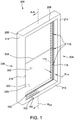
- FIGS 1-5 illustrate example embodiments of a controller indicated generally at 100 for use with an electrostatic window indicated generally at 200 according to example embodiments of the present disclosure.
- the electrostatic window 200 includes window 202 and a selectively positionable electrostatic shutter 204.
- the controller 100 selectively positions the shutter 204 to control the radiance transmittance, e.g., sunlight, passing through the window 202.
- the electrostatic window 200 and the controller 100 may be used to control radiance transmittance in a variety of implementations, for example and without limitation, a door, a window, a skylight, a moon roof, a canopy, and the like.
- the electrostatic window 200 includes a frame 206 that defines a boundary of the window 202.
- the frame 206 includes a head 208 and a sill 210 and defines a window axis A 202 that extends therebetween.
- the head 208 and the sill 210 are generally parallel to each other.
- the frame 206 further includes a first jamb 212 and a second jamb 214 extending generally parallel to each other between the head 208 and the sill 210.
- the window 202 includes a pane unit 216 (e.g., sash) including one or more panes, e.g., glass panes, which are supported by the frame 206.
- the pane unit 216 includes a first pane 220 and a second pane 222 that are both supported by the frame 206.
- the first pane 220 and the second pane 222 are arranged such that they spaced apart by a distance, d 216 .
- the frame 206 includes a first side 224 and a second side 226. The first side 224 and second side 226 are on opposite sides of the pane unit 216.
- the first side 224 may be associated with an exterior of the electrostatic window 200
- the second side 226 may be associated with an interior of the electrostatic window 200.
- the electrostatic window 200 may be mounted to a building such that the first side 224 is exposed to the environment, and the second side 226 is exposed to the interior of a room.
- Fig. 2 is a cross-sectional view of the electrostatic window 200 and controller 100 taken along line A-A.
- the first pane 220 includes a surface which coated with a pane conductive layer 230.
- a pane dielectric layer 232 is coated on top of the pane conductive layer 230.
- the first pane 220 in combination with the pane conductive layer 230 functions as a first electrode 234 that is fixed relative to the frame 206.
- the first pane 220 may be made of a conductive material (e.g., Indium tin oxide) and serve as the first electrode without using a pane conductive layer 230.
- an isolation layer is applied to first pane 220 to separate the first pane 220 and the shutter 204.
- the shutter 204 is coated with a shutter conductive layer 236.
- the shutter 204 may be formed of a conductive material.
- the shutter 204 functions as a second electrode 238 that interacts with first electrode 234 as described herein.
- the second electrode 238 is a variable position electrode such that at least a portion of the second electrode 238 is moveable relative to the frame 206 and relative to the first electrode 234.
- the shutter 204 includes a top edge 240 and a bottom edge 242.
- the shutter 204 may be disposed between the first pane 220 and the second pane 222, and at least a portion of the top edge 240 may be coupled to an isolation layer on the first pane 220.
- the shutter 204 may be arranged in a plurality of configurations.
- a first configuration also referred to herein as the stowed position
- the shutter 204 is rolled up into a coiled position. Accordingly, when the shutter 204 is in the first configuration, the shutter 204 generally does not block radiance from passing through the window 202, i.e., the shutter 204 is in a stowed position.
- the shutter 204 when the shutter 204 is rolled up, the shutter 204 may at least partially be covered by the head 208.
- the top edge 240 and the bottom edge 242 may be arranged in proximity to each other generally near the head 208.
- the shutter 204 may be formed of a material configured to block light from passing through the window 202.
- the shutter 204 may be formed of a polymer material that is substantially opaque.
- the polymer may be coated with reflective material and/or the shutter conductive layer 236 may itself be reflective.
- the shutter 204 may be designed to fully or at least partially block or reflect light.
- the shutter 204 may be formed of any material or coated with any material to enable the shutter 204 to function as described herein.
- the shutter 204 includes material properties and dimensions that enable the shutter 204 to be arranged in the first configuration absent an applied force.
- a force e.g., an electrostatic force
- the shutter 204 may unfurl from the first configuration, such that the bottom edge 242 extends downward along the window axis A 202 away from the head 208 toward the sill 210, and such that the shutter 204 substantially blocks radiance passing through at least a portion of the window 202.
- a first electrical lead 102 couples the first electrode 234 to a voltage source 106
- a second electrical lead 104 couples the second electrode 238 to the voltage source 106.
- the controller 100 is communicatively coupled to the voltage source 106, and is configured to selectively apply, using the voltage source 106, a voltage difference between the first electrical lead 102 and the second electrical lead 104 to create a corresponding voltage difference between the first electrode 234 and the second electrode 238.
- the voltage difference creates an attractive force between the first electrode 234 and the second electrode 238 which causes the second electrode 238 to move relative to the first electrode 234.
- the applied voltage difference causes the shutter 204 to unfurl along the window axis A 202 towards a second configuration, enabling the shutter 204 to at least partially block radiance from passing through the window 202.
- controller 100 removes the applied voltage, the shutter 204 will recoil and return to the first configuration.
- the controller 100 and the voltage source 106 are positioned in the sill 210.
- the controller 100 and the voltage source 106 may be positioned at any suitable location within the electrostatic window 200.
- the controller 100 and the voltage source 106 may be integrated with one another, or may be separate devices.
- the voltage source supplies a constant voltage (e.g., -300VDC (Voltage direct current) to the first electrode 234 via the first electrical lead 102, and the voltage supplied to the second electrode 238 via the second electrical lead 104 is varied to control the voltage difference between the first electrode 234 and the second electrode 238.
- a constant voltage e.g., -300VDC (Voltage direct current)
- the voltage supplied to the second electrode may be varied between -300VDC and +300VDC (resulting in a voltage difference varying between 0VDC and 600VDC).
- the shutter 204 may unfurl from the first configuration to the second configuration.
- the shutter 204 In the second configuration, the shutter 204 is in a completely unfurled position.
- the bottom edge 242 of the shutter 204 is proximate the sill 210. Accordingly, in the second configuration, the shutter 204 generally blocks all radiance from passing through the window 202.
- the first voltage difference is a voltage difference sufficient to completely unroll the shutter 204.
- the controller 100 may also apply a voltage difference having a magnitude lower than the first voltage difference, in order to hold the shutter 204 at one or more intermediate configurations between the first configuration and the second configuration.
- the shutter 204 is partially rolled out and the bottom edge 242 of the shutter 204 is positioned between the head 208 and the sill 210.
- the intermediate configurations may include, for example and without limitation, a halfway configuration, a quarter configuration, and/or a three-quarters configuration.
- the halfway configuration the shutter 204 is unrolled out such that the bottom edge 242 of the shutter 204 is disposed approximately halfway between the head 208 and the sill 210.
- the quarter configuration the shutter 204 is unrolled such that the bottom edge 242 of the shutter 204 is disposed approximately a quarter of the way from the head 208 to the sill 210 of the frame 206.
- the controller 100 may be configured to position the shutter 204 in any suitable intermediate configuration.
- the controller 100 is communicatively coupled to a sensor system 110 that detects and senses the motion and/or position of the shutter 204.
- the controller 100 receives sensor signals from the sensor system 110 indicating the position of the shutter 204. Based on the sensor signals received from the sensor system 110, the controller 100 transmits signals to the voltage source 106 to control the applied voltage difference between the first electrical lead 102 and the second electrical lead 104, as described above.
- the sensor system 110 includes one or more sensors 112 capable of detecting the position and/or motion of the shutter 204.
- each sensor 112 includes at least one transmitter 114 and at least one receiver 116, and the transmitter 114 transmits a sensor signal that is detectable by the receiver 116.
- the sensor signal detected by the receiver 116 is used to sense the position of the shutter 204.
- the transmitter 114 may be an infrared (IR) transmitter 114
- the receiver 116 may be an IR receiver 116, with the transmitter 114 emitting an IR sensor signal that is detectable by the receiver 116.
- the transmitter 114 and the receiver 116 are mounted on opposite sides of the pane unit 216.
- the transmitter 114 and the receiver 116 may be mounted to either the first jamb 212 or the second jamb 214 on opposite sides of the pane unit 216.
- the transmitter 114 may be mounted on the first side 224, and the receiver 116 may be mounted on the second side 226.
- the transmitter 114 may be mounted to the second side 226, and the receiver 116 may be mounted to the first side 224.
- the transmitter 114 emits a sensor signal that passes through the pane unit 216 and is received by the receiver 116 on the other side of the pane unit 216.
- the sensor 112 is arranged such that the transmitter 114 directs a sensor signal towards the receiver 116.
- the transmitter 114 and the corresponding receiver 116 are arranged along a line that is perpendicular to the window axis A 202 .
- the sensors 112 may be positioned in a plurality of predetermined locations along the window axis A 202 , thereby enabling the sensors 112 to detect the position of the shutter 204 at these predetermined locations.
- the sensor system 110 includes three sensors 112 arranged in three predetermined locations: a first position, a second position, and a third position.
- the first position is located approximately a quarter of the way from the head 208 to the sill 210.
- the second position is located at approximately halfway between the head 208 and the sill 210.
- the third position is located approximately three quarters of the way from the head 208 to the sill 210.
- the sensor system 110 may include any number of sensors 112 arranged in any number of sensor locations enabling the position of the shutter 204 to be monitored and controlled as described herein.
- the sensor signal emitted by the transmitter 114 is unimpeded by the shutter 204 such that a complete or undisrupted sensor signal is detected by the receiver 116. If the shutter 204 unrolls such that a portion of the shutter 204 is disposed between the transmitter 114 and the receiver 116, the shutter 204 generally blocks or otherwise disrupts the sensor signal. Accordingly, when the shutter 204 is positioned between the transmitter 114 and the receiver 116, the receiver detects an altered sensor signal.
- the altered sensor signal may include a partial, interrupted, or modified sensor signal.
- the shutter 204 when the shutter 204 is unfurled halfway between the head 208 and the sill 210, the shutter 204 is disposed between the transmitter 114 and receiver 116 located at the second position. Accordingly, the sensor 112 mounted at the second position detects that the shutter 204 is unfurled at least the second position.
- the controller 100 is communicatively coupled to a user interface 150.
- the user interface 150 supports one or more user input devices 152 that transmit sensor signals to the controller 100 to control operation of the shutter 204.
- User input devices 152 may include knobs, dials, switches, and the like.
- the user input devices 152 include a slider that is capable of detecting a user's finger position on the slider using capacitive electrodes.
- a user may adjust the user input devices 152 in order to select or control one or more operations executed by the controller 100.
- the user input devices 152 may be used to select a desired position of the shutter 204.
- a user may adjust the user input device 152 to select that the shutter 204 be unfurled to the first position.
- the controller 100 may enable the sensors 112 located at the first position and disable the sensors 112 located at other positions, and the controller 100 may transmit a sensor signal to the voltage source to apply a voltage to cause the shutter 204 to unfurl until the sensor 112 located at the first position detects the shutter 204.
- the user interface 150 may be coupled to the frame 206.
- the user interface 150 may be coupled to the first side 224 of the frame 206 such that a user may easily access the user interface 150 and the one or more user input devices 152.
- the user interface 150 and user input devices 152 may include additional or alternative devices or components used to adjust a parameter of the controller 100 and/or the electrostatic window 200.
- the transmitter 114 and the receiver 116 are mounted to the same side of the pane unit 216. Accordingly, the sensor signal emitted by the transmitter 114 may reflect off of at least a portion of the shutter 204. The reflected sensor signal is detectable by the receiver 116. When the shutter 204 is not disposed in a path of the sensor signal, no sensor signal is reflected and/or detected by the receiver 116. The angle and magnitude of the reflected sensor signal and may be used to determine the position of the shutter 204.
- the sensor system 110 may include alternative or additional components and/or devices used to detect and/or sense the motion and position of the shutter 204 to enable the controller 100 and electrostatic window 200 to function as described herein.
- the sensor system 110 may include for example and without limitation, motion detection sensors, accelerometers, potentiometers, and the like.
- Fig. 3 illustrates an example embodiment of a controller 300 (e.g., the controller 100) for controlling the electrostatic window 200.
- the voltage source 106 shown in Fig. 1
- the controller 300 is coupled to the sensor 112 including the transmitter 114 and the receiver 116 mounted on opposite sides of the pane unit 216.
- the transmitter 114 and the receiver 116 are coupled to a respective sensor voltage source 306 that supplies power to the associated transmitter 114 or receiver 116.
- the sensor 112 detects the unfurled position of the shutter 204, and the controller 300 adjusts an electrostatic force to control the position of the shutter 204 based on feedback from the sensor 112, as described herein. More specifically, in the example embodiment, the controller 300 applies a constant voltage V C to the first electrode 234 (e.g., the first pane 220).
- the constant voltage V c may be in the range of, for example, - 100VDC to -400 VDC. In this example embodiment, the voltage V c is approximately -300 VDC.
- the controller 300 adjusts an applied voltage V a to the second electrode 238 (e.g., the the shutter 204) creating a voltage difference between voltage V c on the first electrode 234 and the voltage V a on the second electrode 238. This potential difference generates an electrostatic force that controls unfurling of the shutter 204.
- the transmitter 114 and the receiver 116 receive an applied voltage VCC s from respective sensor voltage sources 306. Further, the receiver 116 includes a receiver output 308, and the voltage on the receiver output 308 depends on the signal detected by the receiver 116 and the applied voltage VCC s . Specifically, when the shutter 204 is not disposed between the transmitter 114 and the receiver 116, the receiver 116 detects an undisrupted signal from the transmitter 114. When the receiver 116 detects an undisrupted signal, the receiver 116 outputs a first voltage (e.g., a low voltage) on the receiver output 308.
- a first voltage e.g., a low voltage
- the receiver 116 detects a disrupted signal (e.g., a reduced signal or no signal).
- a disrupted signal e.g., a reduced signal or no signal.
- the receiver 116 outputs a second voltage (e.g., a high voltage) on the receiver output 308.
- the low voltage is approximately 30% of VCC s and the high voltage is approximately 70% of VCC s .
- the receiver output 308 has a first voltage. In contrast, if the sensor 112 detects the shutter 204, the receiver output 308 has a second, higher voltage.
- the controller 300 further includes a first amplifier 310.
- the first amplifier 310 includes a first amplifier input 309 coupled to the receiver output 308 and a first amplifier output 312.
- the first amplifier output 312 outputs the voltage on the first amplifier input 309 amplified by a first gain of the first amplifier 310.
- the first gain is negative. Accordingly, if the receiver output 308 is the low voltage, the voltage on the first amplifier output 312 is a high voltage (e.g., close to VCC s ). If, however, the receiver output 308 is the high voltage, the voltage on the first amplifier output 312 is a low voltage (e.g., close to 0VDC).
- the first amplifier output 312 is coupled to a first bias node 314 through a resistor 315.
- the first bias node 314 is coupled to a first bias input 316 that is in turn coupled to the first amplifier output 312 through the resistor 315.
- the first bias node 314 is also coupled to a second bias input 320 and a first bias output 322.
- the first bias input 316, second bias input 320, and first bias output 322 are all on the same wire and accordingly have the same voltage.
- the second bias input 320 is connected to a bias input node 321 that is set such that, in the absence of the sensor 112 detecting the shutter 204, a bias voltage is supplied to a second amplifier 324 such that a voltage sufficient to cause the shutter 204 to unfurl is applied to the second electrode 238.
- the first amplifier output 312 controls the first bias input 316 and, accordingly, the first bias output 322 supplied to the second amplifier 324. Accordingly, changes in the voltage on the first amplifier output 312 (i.e., due to detection of the shutter 204 by the sensor 112) cause changes in the voltage supplied to the second amplifier 324.
- the resistor 315 limits the impact of changes in the voltage on the first amplifier output 312 and functions as part of a low pass filter (as well as causing a phase shift).
- the second amplifier 324 has a second gain.
- the second gain is a positive gain.
- a voltage on a second amplifier output 328 may be approximately one hundred times larger than the voltage input to the second amplifier 324 (i.e., the voltage on the first bias output 322).
- the voltage on the second amplifier output 328 is supplied to the second electrode 238 (i.e., via the second electrical lead 104).
- the voltage applied to the first electrode 234 is -300VDC.
- the voltage input into the first amplifier 310 is approximately 30% of VCC s
- the voltage output by the first amplifier 310 is approximately VCC s
- the voltage output by the second amplifier is close to +300VDC, resulting in a voltage difference between the first electrode 234 and the second electrode 238 of almost 600VDC (causing the shutter 204 to transition towards totally unfurling).
- the voltage input into the first amplifier 310 is approximately 70% of VCC s
- the voltage output by the first amplifier 310 is close to zero
- the voltage output by the second amplifier is close to -300VDC, resulting in a voltage difference between the first electrode 234 and the second electrode 238 of almost zero (causing the shutter 204 to transition towards totally rolling up).
- the voltage applied to the second electrode may be in a range from 0 to +300VDC, resulting in a voltage difference between the first electrode 234 and the second electrode 238 between 300VDC and 600VDC. This "intermediate" voltage difference results in the shutter 204 being held at approximately the same height as the sensor 112 (e.g., between a totally unfurled and totally rolled up state).
- the controller 300 causes the shutter 204 to stop unfurling proximate the sensor 112.
- Fig. 4 illustrates an example embodiment of a controller 400 (e.g., the controller 100) for controlling the electrostatic window 200.
- the controller 400 is coupled to a sensor system 110 having three sensors 112: a first sensor, a second sensor, and a third sensor, positioned at three different predetermined locations along the window axis A 202 , capable of detecting the position of the shutter 204 at these predetermined locations.
- Each of the sensors 112 includes a transmitter 114 and a receiver 116 mounted on opposite sides of the pane unit 216 as illustrated in Fig. 1 and 2 .
- the controller 400 operates similar to the controller 300 (shown in Fig. 3 ) to control the position of the shutter 204, based on feedback from the sensor 112.
- Using three sensors 112, as described herein, enables stopping unfurling of the shutter 204 at three different heights (depending on which particular sensor 112 is being used).
- the sensor system 110 may include any number of sensors 112 positioned in any number of predetermined locations.
- the controller 400 includes a switch 410 that selectively connects at least one sensor voltage source 411 to each of the sensors 112.
- the switch 410 selectively enables at least one of first, second, or third sensors 112 while disabling the remaining sensors 112. More specifically, the switch 410 may apply a voltage from sensor voltage source 411 to at least one of first, second or third sensor 112, while disconnecting any applied voltage from sensor voltage source 411 from the remaining sensors 112.
- the switch 410 enables one of the sensors 112 in order to selectively set a targeted predetermined position of the shutter 204. For example, if the switch 410 enables the second sensor, while disabling the first and third sensors, the sensor system 110 is capable of detecting when the shutter 204 is at the second position. Additionally or alternatively, the switch 410 may enable the first sensor, while disabling the second sensor and third sensor, such that the sensor system 110 is capable of detecting when the shutter 204 is at the first position. Additionally or alternatively, the switch 410 may enable the third sensor while disabling the first sensor and the second sensor, such that the sensor system 110 is capable of detecting when the shutter 204 is at the third position.
- controller 400 may transmit a signal to the switch 410 based on signals received from the user interface 150, such that the user input devices 152 may be used to select a targeted predetermined position of the shutter 204.
- the controller 400 is further coupled to a first amplifier 412.
- the first amplifier 412 functions somewhat similar to the first amplifier 310 (shown in Fig. 3 ).
- the first amplifier 412 is a comparator with a first inverting lead 416, a first non-inverting lead 418, and a first amplifier output 420.
- Using a comparator facilitates creating a logical voltage level on the first amplifier output 420.
- this may result in continuous back and forth movement of the shutter 204, which increases power consumption.
- the first amplifier 412 is not implemented as a comparator.
- a low pass filter may be used to condition the output of the first amplifier 412.
- the receivers 116 are selectively connected to a receiver output 417 through the switch 410.
- the first inverting lead 416 is coupled to the receiver output 417.
- a biasing voltage 422 supplied to the first non-inverting lead 418 sets the output voltage of the first amplifier 412 (on a first amplifier output 420) in a range from 0 to VCC s .
- the biasing voltage also reduces the influence of sunlight (or other ambient light) on the operation of the sensor 112. Further, in this embodiment, if the shutter 204 completely blocks the sensor 112, the output voltage for the first amplifier 412 is close to 0VDC. If the shutter 204 does not block the sensor 112, the output voltage is close to VCC s . Further, if the shutter 204 partially blocks the sensor 112, the output voltage is between 0VDC and VCC s .
- an additional sensor may be coupled to the first non-inverting lead 418 to reduce the influence of sunlight (and other ambient light) on the output voltage of the first amplifier 412. This additional sensor may be positioned so that the shutter 204 does not block the additional sensor (regardless of the position of the shutter 204).
- the voltage on the first amplifier output 420 is input to a first filter 424, which generates an output voltage on a node first input 432.
- the first filter 424 is a low pass filter operable to condition the output of the first amplifier output 420.
- the controller 400 further includes a first node 430 connected to the node first input 432, a node second input 434, and a node output 436.
- a reference source 437 is coupled to the node second input 434 and supplies a reference voltage.
- the controller 400 further includes a second amplifier 450.
- the reference voltage shifts the voltage on a second non-inverting lead 454 of the second amplifier 450 to be in a range similar to an output voltage of the second amplifier 450.
- the output voltage of the first amplifier 412 is close to VCC s (corresponding to the shutter 204 not blocking the sensor 112)
- the voltage on the second non-inverting lead 454 will be close to +3VDC
- the output voltage of the second amplifier 450 will be close to +300VDC (with a positive gain of a factor of one hundred).
- the output voltage of the first amplifier 412 is close to zero (corresponding to the shutter 204 totally blocking the sensor)
- the voltage on the second non-inverting lead 454 will be close to -3VDC
- the output voltage of the second amplifier 450 will be close to -300VDC.
- the voltage on the second non-inverting lead 454 will be an intermediate voltage between -3VDC and +3VDC (which will result in the shutter 204 being held at a position proximate the sensor 112) .
- a second inverting lead 452 for the second amplifier 450 is coupled to the output of the second amplifier 450 via a feedback loop 451.
- the controller 400 may also include various resistors 460, as shown in Fig. 4 .
- the voltage output by the second amplifier 450 is supplied to the second electrode 438 (via an output lead 456). Accordingly, the voltage output by the second amplifier 450 controls the voltage difference between the first electrode 234 and the second electrode 438, which controls the unfurling (and position) of the shutter 204.
- the controller 100, 300, and/or 400 may further include one or more additional electronic components and/or devices that enable the controller 100, 300, and 400 to function as described herein.
- the controller 100, 300, and 400 may include one or more filters, capacitors, resistors, and the like to enable the controller 100, 300, and 400 to function as described herein.
- the controller 100 is implemented using one or more circuit components.
- the controller 100 may be implemented using a processor that is communicatively coupled to a memory.
- the memory may store a plurality of instructions that, when executed by the processor, cause the controller 100 to control a position of the shutter 204 as described above.
- the controller 100 is implemented on a printed circuit board (PCB). Further, in some embodiments, the controller 100 may be implemented using a high voltage flyback converter, which may facilitate reducing the size of the PCB.
- the controller 100 may also include a battery backup (e.g., to supply power to the controller 100 in the event of a power failure).
- Fig. 5 is a process flow chart of an example method 500 for controlling the position of a shutter of an electrostatic window (e.g., the shutter 204 of the electrostatic window 200).
- the method 500 may be implemented by controller 100 (e.g., controller 300 or 400), which may execute one or more operations to selectively position the shutter 204 in one or more predetermined positions.
- Method 500 includes applying 502 a first voltage across the first electrode 234 and the second electrode 238.
- Applying 402 the first voltage includes the controller 100 causing a voltage source to apply the first voltage across the first electrode 234 and the second electrode 238.
- the first voltage is associated with a voltage difference between the first electrode 234 and the second electrode 238 that is required to unfurl the shutter 204 from the first configuration to the second configuration.
- Method 500 further includes detecting 504 if the shutter 204 has unfurled to a predetermined position using one or more of the sensors 112.
- the one or more sensors 112 may be arranged to determine if the shutter 204 is in one or more unfurled positions, e.g., halfway unfurled.
- One more sensors 112 may be arranged in proximity to the shutter 204 to detect the position of the shutter 204. Further, as described above, an additional sensor may be used to reduce the influence of sunlight on the system.
- the sensors 112 may include the transmitter 114 and the receiver 116, such that the receiver 116 detects a signal emitted by the transmitter 114. When the shutter 204 is unfurled between the transmitter 114 and the receiver 116, the sensor 112 transmits a signal to the one or more components of the controller 100 indicating that the shutter 204 is unfurled to a predetermined position.
- Method 500 further includes adjusting 506 the voltage applied between the first electrode 234 and the second electrode 238 (e.g., to hold the shutter 204 at a desired position) using one or more circuit components and/or devices, as described above.
- the controller 100 applies the first voltage across the first electrode 234 and the second electrode 238, causing the shutter 204 to unfurl. If, however, the shutter 204 is disposed between the transmitter 114 and the receiver 116, then the controller 100 applies a voltage across the first electrode 234 and the second electrode 238 that is less than the first voltage, stopping the unfurling of the shutter 204. In the example embodiment, the lower applied voltage across the first electrode 234 and the second electrode 238 holds the shutter 204 at a predetermined location without allowing the shutter 204 to roll back upward or continue to unfurl.
- the terms “about,” “substantially,” “essentially,” and “approximately” when used in conjunction with ranges of dimensions, concentrations, temperatures or other physical or chemical properties or characteristics is meant to cover variations that may exist in the upper and/or lower limits of the ranges of the properties or characteristics, including, for example, variations resulting from rounding, measurement methodology or other statistical variation.
Landscapes
- Engineering & Computer Science (AREA)
- Structural Engineering (AREA)
- Civil Engineering (AREA)
- Architecture (AREA)
- Operating, Guiding And Securing Of Roll- Type Closing Members (AREA)
Abstract
Description
- This application claims priority to
U.S. Provisional Application No. 62/987,466 filed on March 10, 2020 - The present disclosure relates to a controller for an electrostatic shutter, and more particularly, a controller for controlling the position and motion of an electrostatic shutter.
- At least some known electrostatic windows include a positionable shutter that may be selectively rolled up in a stowed position or unfurled such that the shutter blocks or prevents radiation, e.g., sunlight, from entering through the window. Generally, a voltage is applied to the electrostatic window to create an electrostatic force that causes the shutter to unfurl. When the voltage is removed, the shutter rolls back up into the stowed position.
- At least some known electrostatic windows utilize a controller to selectively switch on or switch off the applied voltage. For example, the controller may switch on a voltage supply to the electrostatic window system causing the shutter to unfurl completely. Likewise, the controller may switch off the voltage supply, causing the shutter to roll back up into the stowed position. When the applied voltage is removed, the material properties and dimensions of the shutter cause the shutter to roll upward into the stowed position. For example, the shutter may be suitably biased such that unrolling the shutter stores a tension in the shutter. After the controller switches off the applied voltage, the tension stored in the shutter causes the shutter to recoil to the rolled up position. The material properties of the shutter may affect the rolling and unrolling of the shutter.
- In some cases, environmental factors, e.g., ambient temperature, fatigue, and/or age of the shutter may affect the material properties of the shutter. As such, the applied voltage may not completely unroll the shutter. For example, in some cases, if the stiffness of the shutter is increased, the applied voltage may not generate a sufficient electrostatic force to completely unfurl the shutter. Further, it may be advantageous to unroll the shutter to multiple different positions between a rolled up position and a completely unfurled position, to provide additional control over the amount of radiance that passes through the window.
- Accordingly, it may be advantageous to precisely control the position and motion of an electrostatic shutter.
- One aspect of the present disclosure is directed toward an electrostatic shutter system. The electrostatic shutter system includes an electrostatic shutter configured to be selectively raised and lowered based on a voltage applied to the electrostatic shutter, at least one sensor configured to detect a position of the electrostatic shutter, and a controller communicatively coupled to the electrostatic shutter and the at least one sensor. The controller is configured to apply an initial voltage to the electrostatic shutter to lower the electrostatic shutter, receive an output signal from the at least one sensor indicating the electrostatic shutter has reached a predetermined position, and based on the received output signal from the at least one sensor, apply an updated voltage to the electrostatic shutter to hold the shutter at the predetermined position.
- Yet another aspect of the present disclosure is directed to a control system for positioning an electrostatic shutter. The control system includes at least one sensor configured to detect a position of the electrostatic shutter, and a controller communicatively coupled to the at least one sensor, wherein the controller is configured to control a position of the electrostatic shutter by adjusting a voltage applied to the electrostatic shutter based on signals received from the at least one sensor.
- Yet another aspect of the present disclosure is directed a method for positioning an electrostatic shutter. The method includes applying an initial applied voltage to the electrostatic shutter to lower the electrostatic shutter, receiving an output signal from at least one sensor, wherein the at least one sensor detects a position of the shutter, and based on the received output signal, applying an updated applied voltage to the electrostatic shutter to hold the shutter at a predetermined position.
- Various refinements exist of the features noted in relation to the above-mentioned aspects of the present disclosure. Further features may also be incorporated in the above-mentioned aspects of the present disclosure as well. These refinements and additional features may exist individually or in any combination. For instance, various features discussed below in relation to any of the illustrated embodiments of the present disclosure may be incorporated into any of the above-described aspects of the present disclosure, alone or in any combination.
-
-
FIG. 1 is a perspective view of an example embodiment of an electrostatic window and a controller for controlling the position of a shutter; -
Fig. 2 is a cross-sectional view taken at line A-A shown inFig. 1 ; -
FIG. 3 is an example embodiment of a circuit diagram for the controller for use with the electrostatic window shown inFig. 1 and2 ; -
FIG. 4 is an another example embodiment of a circuit diagram of the controller for use with the electrostatic window shown inFig. 1 and2 ; and -
FIG. 5 is an example embodiment of a process flow diagram for controlling the position of a shutter of an electrostatic window. - Corresponding reference characters indicate corresponding parts throughout the drawings.
-
Figures 1-5 illustrate example embodiments of a controller indicated generally at 100 for use with an electrostatic window indicated generally at 200 according to example embodiments of the present disclosure. Theelectrostatic window 200 includeswindow 202 and a selectively positionableelectrostatic shutter 204. Thecontroller 100 selectively positions theshutter 204 to control the radiance transmittance, e.g., sunlight, passing through thewindow 202. Theelectrostatic window 200 and thecontroller 100 may be used to control radiance transmittance in a variety of implementations, for example and without limitation, a door, a window, a skylight, a moon roof, a canopy, and the like. - In reference to
Fig. 1 and2 , theelectrostatic window 200 includes aframe 206 that defines a boundary of thewindow 202. Theframe 206 includes ahead 208 and asill 210 and defines a window axis A202 that extends therebetween. Thehead 208 and thesill 210 are generally parallel to each other. Theframe 206 further includes afirst jamb 212 and asecond jamb 214 extending generally parallel to each other between thehead 208 and thesill 210. - The
window 202 includes a pane unit 216 (e.g., sash) including one or more panes, e.g., glass panes, which are supported by theframe 206. In this illustrated embodiment, thepane unit 216 includes afirst pane 220 and asecond pane 222 that are both supported by theframe 206. Thefirst pane 220 and thesecond pane 222 are arranged such that they spaced apart by a distance, d216. Additionally, theframe 206 includes afirst side 224 and asecond side 226. Thefirst side 224 andsecond side 226 are on opposite sides of thepane unit 216. Thefirst side 224 may be associated with an exterior of theelectrostatic window 200, and thesecond side 226 may be associated with an interior of theelectrostatic window 200. For example, theelectrostatic window 200 may be mounted to a building such that thefirst side 224 is exposed to the environment, and thesecond side 226 is exposed to the interior of a room. -
Fig. 2 is a cross-sectional view of theelectrostatic window 200 andcontroller 100 taken along line A-A. In this embodiment, thefirst pane 220 includes a surface which coated with a paneconductive layer 230. A panedielectric layer 232 is coated on top of the paneconductive layer 230. Accordingly, thefirst pane 220 in combination with the paneconductive layer 230 functions as afirst electrode 234 that is fixed relative to theframe 206. Alternatively, thefirst pane 220 may be made of a conductive material (e.g., Indium tin oxide) and serve as the first electrode without using a paneconductive layer 230. Further, in some embodiments, an isolation layer is applied tofirst pane 220 to separate thefirst pane 220 and theshutter 204. - In this illustrated embodiment, the
shutter 204 is coated with a shutterconductive layer 236. In some other example embodiments, theshutter 204 may be formed of a conductive material. In either configuration, theshutter 204 functions as asecond electrode 238 that interacts withfirst electrode 234 as described herein. Thesecond electrode 238 is a variable position electrode such that at least a portion of thesecond electrode 238 is moveable relative to theframe 206 and relative to thefirst electrode 234. Theshutter 204 includes atop edge 240 and abottom edge 242. Theshutter 204 may be disposed between thefirst pane 220 and thesecond pane 222, and at least a portion of thetop edge 240 may be coupled to an isolation layer on thefirst pane 220. - The
shutter 204 may be arranged in a plurality of configurations. In a first configuration (also referred to herein as the stowed position), theshutter 204 is rolled up into a coiled position. Accordingly, when theshutter 204 is in the first configuration, theshutter 204 generally does not block radiance from passing through thewindow 202, i.e., theshutter 204 is in a stowed position. In some embodiments, when theshutter 204 is rolled up, theshutter 204 may at least partially be covered by thehead 208. In addition, when theshutter 204 is rolled up, thetop edge 240 and thebottom edge 242 may be arranged in proximity to each other generally near thehead 208. - The
shutter 204 may be formed of a material configured to block light from passing through thewindow 202. For example, theshutter 204 may be formed of a polymer material that is substantially opaque. The polymer may be coated with reflective material and/or the shutterconductive layer 236 may itself be reflective. Theshutter 204 may be designed to fully or at least partially block or reflect light. In other example embodiments, theshutter 204 may be formed of any material or coated with any material to enable theshutter 204 to function as described herein. - The
shutter 204 includes material properties and dimensions that enable theshutter 204 to be arranged in the first configuration absent an applied force. When a force is applied (e.g., an electrostatic force), theshutter 204 may unfurl from the first configuration, such that thebottom edge 242 extends downward along the window axis A202 away from thehead 208 toward thesill 210, and such that theshutter 204 substantially blocks radiance passing through at least a portion of thewindow 202. - A first
electrical lead 102 couples thefirst electrode 234 to avoltage source 106, and a secondelectrical lead 104 couples thesecond electrode 238 to thevoltage source 106. Further, thecontroller 100 is communicatively coupled to thevoltage source 106, and is configured to selectively apply, using thevoltage source 106, a voltage difference between the firstelectrical lead 102 and the secondelectrical lead 104 to create a corresponding voltage difference between thefirst electrode 234 and thesecond electrode 238. The voltage difference creates an attractive force between thefirst electrode 234 and thesecond electrode 238 which causes thesecond electrode 238 to move relative to thefirst electrode 234. Specifically, the applied voltage difference causes theshutter 204 to unfurl along the window axis A202 towards a second configuration, enabling theshutter 204 to at least partially block radiance from passing through thewindow 202. Likewise, ifcontroller 100 removes the applied voltage, theshutter 204 will recoil and return to the first configuration. - In the embodiment shown in
Fig. 2 , thecontroller 100 and thevoltage source 106 are positioned in thesill 210. Alternatively, thecontroller 100 and thevoltage source 106 may be positioned at any suitable location within theelectrostatic window 200. Further, thecontroller 100 and thevoltage source 106 may be integrated with one another, or may be separate devices. - In the example embodiment, the voltage source supplies a constant voltage (e.g., -300VDC (Voltage direct current) to the
first electrode 234 via the firstelectrical lead 102, and the voltage supplied to thesecond electrode 238 via the secondelectrical lead 104 is varied to control the voltage difference between thefirst electrode 234 and thesecond electrode 238. For example, when the constant voltage applied to thefirst electrode 234 is -300VDC, the voltage supplied to the second electrode may be varied between -300VDC and +300VDC (resulting in a voltage difference varying between 0VDC and 600VDC). Those of skill in the art will appreciate that other voltage schemes may be used in other embodiments. - When the
controller 100 applies a first voltage difference between thefirst electrode 234 and thesecond electrode 238, theshutter 204 may unfurl from the first configuration to the second configuration. In the second configuration, theshutter 204 is in a completely unfurled position. In some example embodiments, when theshutter 204 is in the second configuration, thebottom edge 242 of theshutter 204 is proximate thesill 210. Accordingly, in the second configuration, theshutter 204 generally blocks all radiance from passing through thewindow 202. Accordingly, the first voltage difference is a voltage difference sufficient to completely unroll theshutter 204. When thecontroller 100 removes the applied voltage difference, theshutter 204 rolls up again, returning to the first configuration. - The
controller 100 may also apply a voltage difference having a magnitude lower than the first voltage difference, in order to hold theshutter 204 at one or more intermediate configurations between the first configuration and the second configuration. In the intermediate configurations, theshutter 204 is partially rolled out and thebottom edge 242 of theshutter 204 is positioned between thehead 208 and thesill 210. - The intermediate configurations may include, for example and without limitation, a halfway configuration, a quarter configuration, and/or a three-quarters configuration. In the halfway configuration, the
shutter 204 is unrolled out such that thebottom edge 242 of theshutter 204 is disposed approximately halfway between thehead 208 and thesill 210. In the quarter configuration, theshutter 204 is unrolled such that thebottom edge 242 of theshutter 204 is disposed approximately a quarter of the way from thehead 208 to thesill 210 of theframe 206. Similarly, in the three-quarters configuration, theshutter 204 is rolled out such that thebottom edge 242 of theshutter 204 is disposed approximately three-quarters of the way from thehead 208 to thesill 210. Alternatively or additionally, thecontroller 100 may be configured to position theshutter 204 in any suitable intermediate configuration. - The
controller 100 is communicatively coupled to asensor system 110 that detects and senses the motion and/or position of theshutter 204. Thecontroller 100 receives sensor signals from thesensor system 110 indicating the position of theshutter 204. Based on the sensor signals received from thesensor system 110, thecontroller 100 transmits signals to thevoltage source 106 to control the applied voltage difference between the firstelectrical lead 102 and the secondelectrical lead 104, as described above. - The
sensor system 110 includes one ormore sensors 112 capable of detecting the position and/or motion of theshutter 204. In the example embodiment, eachsensor 112 includes at least onetransmitter 114 and at least onereceiver 116, and thetransmitter 114 transmits a sensor signal that is detectable by thereceiver 116. The sensor signal detected by thereceiver 116 is used to sense the position of theshutter 204. For example, thetransmitter 114 may be an infrared (IR)transmitter 114, and thereceiver 116 may be anIR receiver 116, with thetransmitter 114 emitting an IR sensor signal that is detectable by thereceiver 116. - In reference to
Figs. 1 and2 , thetransmitter 114 and thereceiver 116 are mounted on opposite sides of thepane unit 216. For example, thetransmitter 114 and thereceiver 116 may be mounted to either thefirst jamb 212 or thesecond jamb 214 on opposite sides of thepane unit 216. For example, thetransmitter 114 may be mounted on thefirst side 224, and thereceiver 116 may be mounted on thesecond side 226. Alternatively or additionally, thetransmitter 114 may be mounted to thesecond side 226, and thereceiver 116 may be mounted to thefirst side 224. Thetransmitter 114 emits a sensor signal that passes through thepane unit 216 and is received by thereceiver 116 on the other side of thepane unit 216. Thesensor 112 is arranged such that thetransmitter 114 directs a sensor signal towards thereceiver 116. In this illustrated embodiment, thetransmitter 114 and the correspondingreceiver 116 are arranged along a line that is perpendicular to the window axis A202. - The
sensors 112 may be positioned in a plurality of predetermined locations along the window axis A202, thereby enabling thesensors 112 to detect the position of theshutter 204 at these predetermined locations. In this illustrated embodiment, thesensor system 110 includes threesensors 112 arranged in three predetermined locations: a first position, a second position, and a third position. The first position is located approximately a quarter of the way from thehead 208 to thesill 210. The second position is located at approximately halfway between thehead 208 and thesill 210. The third position is located approximately three quarters of the way from thehead 208 to thesill 210. In other words, if theshutter 204 is unrolled out to the first position, then approximately a quarter of thewindow 202 is blocked by theshutter 204. In other example embodiments, thesensor system 110 may include any number ofsensors 112 arranged in any number of sensor locations enabling the position of theshutter 204 to be monitored and controlled as described herein. - When the
shutter 204 is in the first configuration, the sensor signal emitted by thetransmitter 114 is unimpeded by theshutter 204 such that a complete or undisrupted sensor signal is detected by thereceiver 116. If theshutter 204 unrolls such that a portion of theshutter 204 is disposed between thetransmitter 114 and thereceiver 116, theshutter 204 generally blocks or otherwise disrupts the sensor signal. Accordingly, when theshutter 204 is positioned between thetransmitter 114 and thereceiver 116, the receiver detects an altered sensor signal. The altered sensor signal may include a partial, interrupted, or modified sensor signal. - For example, when the
shutter 204 is unfurled halfway between thehead 208 and thesill 210, theshutter 204 is disposed between thetransmitter 114 andreceiver 116 located at the second position. Accordingly, thesensor 112 mounted at the second position detects that theshutter 204 is unfurled at least the second position. - In the example embodiment, the
controller 100 is communicatively coupled to auser interface 150. Theuser interface 150 supports one or moreuser input devices 152 that transmit sensor signals to thecontroller 100 to control operation of theshutter 204.User input devices 152 may include knobs, dials, switches, and the like. For example, in one embodiment, theuser input devices 152 include a slider that is capable of detecting a user's finger position on the slider using capacitive electrodes. A user may adjust theuser input devices 152 in order to select or control one or more operations executed by thecontroller 100. For example, theuser input devices 152 may be used to select a desired position of theshutter 204. For example, a user may adjust theuser input device 152 to select that theshutter 204 be unfurled to the first position. In response, thecontroller 100 may enable thesensors 112 located at the first position and disable thesensors 112 located at other positions, and thecontroller 100 may transmit a sensor signal to the voltage source to apply a voltage to cause theshutter 204 to unfurl until thesensor 112 located at the first position detects theshutter 204. - The
user interface 150 may be coupled to theframe 206. For example, theuser interface 150 may be coupled to thefirst side 224 of theframe 206 such that a user may easily access theuser interface 150 and the one or moreuser input devices 152. Additionally or alternatively, theuser interface 150 anduser input devices 152 may include additional or alternative devices or components used to adjust a parameter of thecontroller 100 and/or theelectrostatic window 200. - In some example embodiments, the
transmitter 114 and thereceiver 116 are mounted to the same side of thepane unit 216. Accordingly, the sensor signal emitted by thetransmitter 114 may reflect off of at least a portion of theshutter 204. The reflected sensor signal is detectable by thereceiver 116. When theshutter 204 is not disposed in a path of the sensor signal, no sensor signal is reflected and/or detected by thereceiver 116. The angle and magnitude of the reflected sensor signal and may be used to determine the position of theshutter 204. - The
sensor system 110 may include alternative or additional components and/or devices used to detect and/or sense the motion and position of theshutter 204 to enable thecontroller 100 andelectrostatic window 200 to function as described herein. For example, thesensor system 110 may include for example and without limitation, motion detection sensors, accelerometers, potentiometers, and the like. -
Fig. 3 illustrates an example embodiment of a controller 300 (e.g., the controller 100) for controlling theelectrostatic window 200. As described above, the voltage source 106 (shown inFig. 1 ) may be incorporated into thecontroller 300. In the example embodiment, thecontroller 300 is coupled to thesensor 112 including thetransmitter 114 and thereceiver 116 mounted on opposite sides of thepane unit 216. Thetransmitter 114 and thereceiver 116 are coupled to a respectivesensor voltage source 306 that supplies power to the associatedtransmitter 114 orreceiver 116. - The
sensor 112 detects the unfurled position of theshutter 204, and thecontroller 300 adjusts an electrostatic force to control the position of theshutter 204 based on feedback from thesensor 112, as described herein. More specifically, in the example embodiment, thecontroller 300 applies a constant voltage VC to the first electrode 234 (e.g., the first pane 220). The constant voltage Vc may be in the range of, for example, - 100VDC to -400 VDC. In this example embodiment, the voltage Vc is approximately -300 VDC. Thecontroller 300 adjusts an applied voltage Va to the second electrode 238 (e.g., the the shutter 204) creating a voltage difference between voltage Vc on thefirst electrode 234 and the voltage Va on thesecond electrode 238. This potential difference generates an electrostatic force that controls unfurling of theshutter 204. - The
transmitter 114 and thereceiver 116 receive an applied voltage VCCs from respectivesensor voltage sources 306. Further, thereceiver 116 includes areceiver output 308, and the voltage on thereceiver output 308 depends on the signal detected by thereceiver 116 and the applied voltage VCCs. Specifically, when theshutter 204 is not disposed between thetransmitter 114 and thereceiver 116, thereceiver 116 detects an undisrupted signal from thetransmitter 114. When thereceiver 116 detects an undisrupted signal, thereceiver 116 outputs a first voltage (e.g., a low voltage) on thereceiver output 308. - In contrast, when the
shutter 204 is disposed between thetransmitter 114 and thereceiver 116, thereceiver 116 detects a disrupted signal (e.g., a reduced signal or no signal). When thereceiver 116 detects a disrupted signal, thereceiver 116 outputs a second voltage (e.g., a high voltage) on thereceiver output 308. In one example, the low voltage is approximately 30% of VCCs and the high voltage is approximately 70% of VCCs. - In other words, in the example embodiment, if the
sensor 112 does not detect theshutter 204, thereceiver output 308 has a first voltage. In contrast, if thesensor 112 detects theshutter 204, thereceiver output 308 has a second, higher voltage. - The
controller 300 further includes afirst amplifier 310. Thefirst amplifier 310 includes afirst amplifier input 309 coupled to thereceiver output 308 and afirst amplifier output 312. Thefirst amplifier output 312 outputs the voltage on thefirst amplifier input 309 amplified by a first gain of thefirst amplifier 310. In the example embodiment, the first gain is negative. Accordingly, if thereceiver output 308 is the low voltage, the voltage on thefirst amplifier output 312 is a high voltage (e.g., close to VCCs). If, however, thereceiver output 308 is the high voltage, the voltage on thefirst amplifier output 312 is a low voltage (e.g., close to 0VDC). - In the example embodiment, the
first amplifier output 312 is coupled to afirst bias node 314 through aresistor 315. Specifically, thefirst bias node 314 is coupled to afirst bias input 316 that is in turn coupled to thefirst amplifier output 312 through theresistor 315. Thefirst bias node 314 is also coupled to a second bias input 320 and afirst bias output 322. Thefirst bias input 316, second bias input 320, andfirst bias output 322 are all on the same wire and accordingly have the same voltage. - The second bias input 320 is connected to a
bias input node 321 that is set such that, in the absence of thesensor 112 detecting theshutter 204, a bias voltage is supplied to asecond amplifier 324 such that a voltage sufficient to cause theshutter 204 to unfurl is applied to thesecond electrode 238. - The
first amplifier output 312 controls thefirst bias input 316 and, accordingly, thefirst bias output 322 supplied to thesecond amplifier 324. Accordingly, changes in the voltage on the first amplifier output 312 (i.e., due to detection of theshutter 204 by the sensor 112) cause changes in the voltage supplied to thesecond amplifier 324. Theresistor 315 limits the impact of changes in the voltage on thefirst amplifier output 312 and functions as part of a low pass filter (as well as causing a phase shift). - The
second amplifier 324 has a second gain. In the example embodiment, the second gain is a positive gain. For example, a voltage on asecond amplifier output 328 may be approximately one hundred times larger than the voltage input to the second amplifier 324 (i.e., the voltage on the first bias output 322). Notably, the voltage on thesecond amplifier output 328 is supplied to the second electrode 238 (i.e., via the second electrical lead 104). - Consider the example where the voltage applied to the
first electrode 234 is -300VDC. In this example, when theshutter 204 is not detected by thesensor 112, the voltage input into thefirst amplifier 310 is approximately 30% of VCCs, the voltage output by thefirst amplifier 310 is approximately VCCs, and the voltage output by the second amplifier is close to +300VDC, resulting in a voltage difference between thefirst electrode 234 and thesecond electrode 238 of almost 600VDC (causing theshutter 204 to transition towards totally unfurling). In contrast, when theshutter 204 completely blocks thesensor 112, the voltage input into thefirst amplifier 310 is approximately 70% of VCCs, the voltage output by thefirst amplifier 310 is close to zero, and the voltage output by the second amplifier is close to -300VDC, resulting in a voltage difference between thefirst electrode 234 and thesecond electrode 238 of almost zero (causing theshutter 204 to transition towards totally rolling up). Notably, when theshutter 204 only partially blocks thesensor 112, the voltage applied to the second electrode may be in a range from 0 to +300VDC, resulting in a voltage difference between thefirst electrode 234 and thesecond electrode 238 between 300VDC and 600VDC. This "intermediate" voltage difference results in theshutter 204 being held at approximately the same height as the sensor 112 (e.g., between a totally unfurled and totally rolled up state). - In other words, until the
sensor 112 detects theshutter 204, the voltage difference between thefirst electrode 234 and thesecond electrode 238 causes theshutter 204 to unfurl. Once theshutter 204 blocks thesensor 112, thecontroller 300 causes theshutter 204 to stop unfurling proximate thesensor 112. -
Fig. 4 illustrates an example embodiment of a controller 400 (e.g., the controller 100) for controlling theelectrostatic window 200. In the example embodiment, thecontroller 400 is coupled to asensor system 110 having three sensors 112: a first sensor, a second sensor, and a third sensor, positioned at three different predetermined locations along the window axis A202, capable of detecting the position of theshutter 204 at these predetermined locations. Each of thesensors 112 includes atransmitter 114 and areceiver 116 mounted on opposite sides of thepane unit 216 as illustrated inFig. 1 and2 . - The
controller 400 operates similar to the controller 300 (shown inFig. 3 ) to control the position of theshutter 204, based on feedback from thesensor 112. Using threesensors 112, as described herein, enables stopping unfurling of theshutter 204 at three different heights (depending on whichparticular sensor 112 is being used). Alternatively or additionally, thesensor system 110 may include any number ofsensors 112 positioned in any number of predetermined locations. - In the illustrated embodiment, the
controller 400 includes aswitch 410 that selectively connects at least onesensor voltage source 411 to each of thesensors 112. Theswitch 410 selectively enables at least one of first, second, orthird sensors 112 while disabling the remainingsensors 112. More specifically, theswitch 410 may apply a voltage fromsensor voltage source 411 to at least one of first, second orthird sensor 112, while disconnecting any applied voltage fromsensor voltage source 411 from the remainingsensors 112. - The
switch 410 enables one of thesensors 112 in order to selectively set a targeted predetermined position of theshutter 204. For example, if theswitch 410 enables the second sensor, while disabling the first and third sensors, thesensor system 110 is capable of detecting when theshutter 204 is at the second position. Additionally or alternatively, theswitch 410 may enable the first sensor, while disabling the second sensor and third sensor, such that thesensor system 110 is capable of detecting when theshutter 204 is at the first position. Additionally or alternatively, theswitch 410 may enable the third sensor while disabling the first sensor and the second sensor, such that thesensor system 110 is capable of detecting when theshutter 204 is at the third position. - Additionally, the
controller 400 may transmit a signal to theswitch 410 based on signals received from theuser interface 150, such that theuser input devices 152 may be used to select a targeted predetermined position of theshutter 204. - The
controller 400 is further coupled to afirst amplifier 412. Thefirst amplifier 412 functions somewhat similar to the first amplifier 310 (shown inFig. 3 ). In this embodiment, thefirst amplifier 412 is a comparator with afirst inverting lead 416, a firstnon-inverting lead 418, and afirst amplifier output 420. Using a comparator facilitates creating a logical voltage level on thefirst amplifier output 420. However, this may result in continuous back and forth movement of theshutter 204, which increases power consumption. Accordingly, in some embodiments, thefirst amplifier 412 is not implemented as a comparator. Alternatively, as described below, a low pass filter may be used to condition the output of thefirst amplifier 412. - The
receivers 116 are selectively connected to areceiver output 417 through theswitch 410. Thefirst inverting lead 416 is coupled to thereceiver output 417. - In this embodiment, a biasing
voltage 422 supplied to the firstnon-inverting lead 418 sets the output voltage of the first amplifier 412 (on a first amplifier output 420) in a range from 0 to VCCs. The biasing voltage also reduces the influence of sunlight (or other ambient light) on the operation of thesensor 112.
Further, in this embodiment, if theshutter 204 completely blocks thesensor 112, the output voltage for thefirst amplifier 412 is close to 0VDC. If theshutter 204 does not block thesensor 112, the output voltage is close to VCCs. Further, if theshutter 204 partially blocks thesensor 112, the output voltage is between 0VDC and VCCs. - In some embodiments, an additional sensor (not shown) may be coupled to the first
non-inverting lead 418 to reduce the influence of sunlight (and other ambient light) on the output voltage of thefirst amplifier 412. This additional sensor may be positioned so that theshutter 204 does not block the additional sensor (regardless of the position of the shutter 204). - The voltage on the
first amplifier output 420 is input to afirst filter 424, which generates an output voltage on a nodefirst input 432. Thefirst filter 424 is a low pass filter operable to condition the output of thefirst amplifier output 420. - The
controller 400 further includes afirst node 430 connected to the nodefirst input 432, a nodesecond input 434, and anode output 436. Areference source 437 is coupled to the nodesecond input 434 and supplies a reference voltage. - The
controller 400 further includes asecond amplifier 450. The reference voltage shifts the voltage on a secondnon-inverting lead 454 of thesecond amplifier 450 to be in a range similar to an output voltage of thesecond amplifier 450. - In the example embodiment, if the output voltage of the
first amplifier 412 is close to VCCs (corresponding to theshutter 204 not blocking the sensor 112), then the voltage on the secondnon-inverting lead 454 will be close to +3VDC, and the output voltage of thesecond amplifier 450 will be close to +300VDC (with a positive gain of a factor of one hundred). In contrast, if the output voltage of thefirst amplifier 412 is close to zero (corresponding to theshutter 204 totally blocking the sensor), then the voltage on the secondnon-inverting lead 454 will be close to -3VDC, and the output voltage of thesecond amplifier 450 will be close to -300VDC. If theshutter 204 partially blocks thesensor 112, the voltage on the secondnon-inverting lead 454 will be an intermediate voltage between -3VDC and +3VDC (which will result in theshutter 204 being held at a position proximate the sensor 112) . - In the example embodiment, a
second inverting lead 452 for thesecond amplifier 450 is coupled to the output of thesecond amplifier 450 via afeedback loop 451. Thecontroller 400 may also includevarious resistors 460, as shown inFig. 4 . - Similar to
controller 300, incontroller 400, the voltage output by thesecond amplifier 450 is supplied to the second electrode 438 (via an output lead 456). Accordingly, the voltage output by thesecond amplifier 450 controls the voltage difference between thefirst electrode 234 and the second electrode 438, which controls the unfurling (and position) of theshutter 204. - The
controller controller controller controller - In the example embodiments illustrated in
Fig. 3 andFig. 4 , thecontroller 100 is implemented using one or more circuit components. Alternatively, as will be appreciated by those of skill in the art, thecontroller 100 may be implemented using a processor that is communicatively coupled to a memory. The memory may store a plurality of instructions that, when executed by the processor, cause thecontroller 100 to control a position of theshutter 204 as described above. - In some embodiments, the
controller 100 is implemented on a printed circuit board (PCB). Further, in some embodiments, thecontroller 100 may be implemented using a high voltage flyback converter, which may facilitate reducing the size of the PCB. Thecontroller 100 may also include a battery backup (e.g., to supply power to thecontroller 100 in the event of a power failure). -
Fig. 5 is a process flow chart of anexample method 500 for controlling the position of a shutter of an electrostatic window (e.g., theshutter 204 of the electrostatic window 200). Themethod 500 may be implemented by controller 100 (e.g.,controller 300 or 400), which may execute one or more operations to selectively position theshutter 204 in one or more predetermined positions. -
Method 500 includes applying 502 a first voltage across thefirst electrode 234 and thesecond electrode 238. Applying 402 the first voltage includes thecontroller 100 causing a voltage source to apply the first voltage across thefirst electrode 234 and thesecond electrode 238. The first voltage is associated with a voltage difference between thefirst electrode 234 and thesecond electrode 238 that is required to unfurl theshutter 204 from the first configuration to the second configuration. -
Method 500 further includes detecting 504 if theshutter 204 has unfurled to a predetermined position using one or more of thesensors 112. The one ormore sensors 112 may be arranged to determine if theshutter 204 is in one or more unfurled positions, e.g., halfway unfurled. - One
more sensors 112 may be arranged in proximity to theshutter 204 to detect the position of theshutter 204. Further, as described above, an additional sensor may be used to reduce the influence of sunlight on the system. Thesensors 112 may include thetransmitter 114 and thereceiver 116, such that thereceiver 116 detects a signal emitted by thetransmitter 114. When theshutter 204 is unfurled between thetransmitter 114 and thereceiver 116, thesensor 112 transmits a signal to the one or more components of thecontroller 100 indicating that theshutter 204 is unfurled to a predetermined position. -
Method 500 further includes adjusting 506 the voltage applied between thefirst electrode 234 and the second electrode 238 (e.g., to hold theshutter 204 at a desired position) using one or more circuit components and/or devices, as described above. - In one embodiment, if the
shutter 204 is not disposed between thetransmitter 114 and thereceiver 116, then thecontroller 100 applies the first voltage across thefirst electrode 234 and thesecond electrode 238, causing theshutter 204 to unfurl. If, however, theshutter 204 is disposed between thetransmitter 114 and thereceiver 116, then thecontroller 100 applies a voltage across thefirst electrode 234 and thesecond electrode 238 that is less than the first voltage, stopping the unfurling of theshutter 204. In the example embodiment, the lower applied voltage across thefirst electrode 234 and thesecond electrode 238 holds theshutter 204 at a predetermined location without allowing theshutter 204 to roll back upward or continue to unfurl. - As used herein, the terms "about," "substantially," "essentially," and "approximately" when used in conjunction with ranges of dimensions, concentrations, temperatures or other physical or chemical properties or characteristics is meant to cover variations that may exist in the upper and/or lower limits of the ranges of the properties or characteristics, including, for example, variations resulting from rounding, measurement methodology or other statistical variation.
- When introducing elements of the present disclosure or the embodiment(s) thereof, the articles "a," "an," "the," and "said" are intended to mean that there are one or more of the elements. The terms "comprising," "including," "containing," and "having" are intended to be inclusive and mean that there may be additional elements other than the listed elements. The use of terms indicating a particular orientation (e.g., "top," "bottom," "side," etc.) is for convenience of description and does not require any particular orientation of the item described.
- As various changes could be made in the above constructions and methods without departing from the scope of the disclosure, it is intended that all matter contained in the above description and shown in the accompanying drawing[s] shall be interpreted as illustrative and not in a limiting sense.
Claims (15)
- A control system for positioning an electrostatic shutter, the control system comprising:at least one sensor configured to detect a position of the electrostatic shutter; anda controller communicatively coupled to the at least one sensor, wherein the controller is configured to control a position of the electrostatic shutter by adjusting a voltage applied to the electrostatic shutter based on signals received from the at least one sensor.
- The control system according to claim 1, wherein the at least one sensor comprises:a transmitter positioned on a first side of the electrostatic shutter and configured to transmit a sensor signal; anda receiver positioned on a second side of the electrostatic shutter opposite the first side and configured to detect the sensor signal transmitted by the transmitter.
- The control system according to claim 2, wherein the transmitter and the receiver comprise an infrared transmitter and an infrared receiver, respectively.
- The control system according to claims 2 or 3, wherein the output signal indicates that the shutter is preventing the sensor signal from reaching the receiver.
- The control system according to any one of claims 1-4, wherein the at least one sensor comprises a plurality of sensors arranged at predetermined plurality of locations relative to the electrostatic shutter.
- The control system according to claim 5, wherein one sensor of the plurality of sensors is positioned approximately halfway between a head and a sill of a window including the electrostatic shutter.
- An electrostatic shutter system comprising:an electrostatic shutter configured to be selectively raised and lowered based on a voltage applied to the electrostatic shutter; andthe control system of claim 1, wherein the controller is configured to:apply an initial voltage to the electrostatic shutter to lower the electrostatic shutter;receive an output signal from the at least one sensor indicating the electrostatic shutter has reached a predetermined position; andbased on the received output signal from the at least one sensor, apply an updated voltage to the electrostatic shutter to hold the shutter at the predetermined position.
- A method for positioning an electrostatic shutter, the method comprising:applying an initial applied voltage to the electrostatic shutter to lower the electrostatic shutter;receiving an output signal from at least one sensor, wherein the at least one sensor detects a position of the shutter; andbased on the received output signal, applying an updated applied voltage to the electrostatic shutter to hold the shutter at a predetermined position.
- The method according to claim 8, wherein receiving an output signal comprises receiving an output signal from at least one sensor including:a transmitter positioned on a first side of the electrostatic shutter and configured to transmit a sensor signal; anda receiver positioned on a second side of the electrostatic shutter opposite the first side and configured to detect the sensor signal transmitted by the transmitter.
- The method according to claim 9, wherein the transmitter and the receiver include an infrared transmitter and an infrared receiver, respectively.
- The method according to claims 9 or 10, wherein receiving an output signal comprises receiving an output signal that indicates that the electrostatic shutter is preventing the sensor signal from reaching the receiver.
- The method according to any of claims 8-11, wherein receiving an output signal comprises receiving a plurality of output signals from a plurality of sensors arranged at predetermined plurality of locations relative to the electrostatic shutter.
- The method according to claim 12, wherein one sensor of the plurality of sensors is positioned approximately halfway between a head and a sill of a window including the electrostatic shutter.
- The method according to claims 12 or 13, wherein one sensor includes a proximity sensor.
- The method according to any of claims 12, 13, or 14, the method further comprising:
receiving a user input from at least one user input device that identifies a predetermined position for the electrostatic shutter to be held at.
Priority Applications (1)
| Application Number | Priority Date | Filing Date | Title |
|---|---|---|---|
| HRP20260036TT HRP20260036T1 (en) | 2020-03-10 | 2021-03-04 | ELECTROSTATIC BLACKOUT SYSTEM |
Applications Claiming Priority (1)
| Application Number | Priority Date | Filing Date | Title |
|---|---|---|---|
| US202062987466P | 2020-03-10 | 2020-03-10 |
Publications (3)
| Publication Number | Publication Date |
|---|---|
| EP3879063A1 true EP3879063A1 (en) | 2021-09-15 |
| EP3879063C0 EP3879063C0 (en) | 2025-12-17 |
| EP3879063B1 EP3879063B1 (en) | 2025-12-17 |
Family
ID=74858347
Family Applications (1)
| Application Number | Title | Priority Date | Filing Date |
|---|---|---|---|
| EP21160738.7A Active EP3879063B1 (en) | 2020-03-10 | 2021-03-04 | Electrostatic shutter system |
Country Status (5)
| Country | Link |
|---|---|
| US (1) | US12024948B2 (en) |
| EP (1) | EP3879063B1 (en) |
| CA (1) | CA3111330C (en) |
| HR (1) | HRP20260036T1 (en) |
| PL (1) | PL3879063T3 (en) |
Families Citing this family (1)
| Publication number | Priority date | Publication date | Assignee | Title |
|---|---|---|---|---|
| MX2022014571A (en) * | 2020-05-22 | 2023-04-10 | Lutron Tech Co Llc | Energy-supply system for supplying energy to an electrical load from a battery. |
Citations (2)
| Publication number | Priority date | Publication date | Assignee | Title |
|---|---|---|---|---|
| WO2012177995A1 (en) * | 2011-06-24 | 2012-12-27 | Magna Mirrors Of America, Inc. | Vehicle window with shade |
| US20140268296A1 (en) * | 2013-03-14 | 2014-09-18 | New Visual Media Group, L.L.C. | Insulated glazing unit and controller providing energy savings and privacy |
Family Cites Families (42)
| Publication number | Priority date | Publication date | Assignee | Title |
|---|---|---|---|---|
| US3989357A (en) | 1974-02-01 | 1976-11-02 | Kalt Charles G | Electro-static device with rolling electrode |
| US4105294A (en) | 1976-08-04 | 1978-08-08 | Dielectric Systems International, Inc. | Electrostatic device |
| US4248501A (en) | 1978-06-16 | 1981-02-03 | Bos-Knox, Ltd. | Light control device |
| US4266339A (en) | 1979-06-07 | 1981-05-12 | Dielectric Systems International, Inc. | Method for making rolling electrode for electrostatic device |
| US4644755A (en) | 1984-09-14 | 1987-02-24 | Esswood Corporation | Emergency refrigerant containment and alarm system apparatus and method |
| US5233459A (en) | 1991-03-06 | 1993-08-03 | Massachusetts Institute Of Technology | Electric display device |
| US6771237B1 (en) | 1993-05-24 | 2004-08-03 | Display Science, Inc. | Variable configuration video displays and their manufacture |
| US6369530B2 (en) | 1996-09-06 | 2002-04-09 | Hunter Douglas Inc. | Battery-powered wireless remote-control motorized window covering assembly having controller components |
| US5793174A (en) | 1996-09-06 | 1998-08-11 | Hunter Douglas Inc. | Electrically powered window covering assembly |
| US7215357B1 (en) | 1998-04-28 | 2007-05-08 | Vrex, Inc. | Line blanker system |
| CN1201181C (en) | 1999-04-06 | 2005-05-11 | 里维奥公司 | Electro-optical glazing structures having scatthering and transparent modes of operation |
| US6897786B1 (en) | 2000-06-14 | 2005-05-24 | Display Science, Inc. | Passively illuminated, eye-catching display for traffic signs |
| US6692646B2 (en) | 2000-08-29 | 2004-02-17 | Display Science, Inc. | Method of manufacturing a light modulating capacitor array and product |
| US7705826B2 (en) | 2002-02-09 | 2010-04-27 | New Visual Media Group, L.L.C. | Flexible video displays and their manufacture |
| US7111952B2 (en) | 2003-03-24 | 2006-09-26 | Lutron Electronics Co., Inc. | System to control daylight and artificial illumination and sun glare in a space |
| JP2004294351A (en) * | 2003-03-28 | 2004-10-21 | Canon Inc | Potential sensor and image forming apparatus |
| US8890456B2 (en) | 2004-05-06 | 2014-11-18 | Mechoshade Systems, Inc. | Automated shade control system utilizing brightness modeling |
| US7684105B2 (en) | 2005-02-24 | 2010-03-23 | National Research Council Of Canada | Microblinds and a method of fabrication thereof |
| US20060000558A1 (en) | 2005-09-13 | 2006-01-05 | James Fennell | Solar-Powered, Low-Voltage, Automatic, Motorized Exterior Window Shading Device |
| US7645977B2 (en) | 2006-11-17 | 2010-01-12 | New Visual Media Group, L.L.C. | Low cost dynamic insulated glazing unit |
| US9539883B2 (en) | 2010-04-23 | 2017-01-10 | Magna Mirrors Of America, Inc. | Window with shade |
| US9550063B2 (en) | 2010-10-14 | 2017-01-24 | II Erich W. Wolf | Apparatus and method using near infrared reflectometry to reduce the effect of positional changes during spinal cord stimulation |
| AU2015203820B2 (en) | 2010-10-14 | 2017-03-02 | Wavegate Corporation | Apparatus and method using near infrared reflectometry to reduce the effect of positional changes during spinal cord stimulation |
| US10989977B2 (en) * | 2011-03-16 | 2021-04-27 | View, Inc. | Onboard controller for multistate windows |
| JP5736906B2 (en) | 2011-03-30 | 2015-06-17 | 三菱マテリアル株式会社 | Infrared sensor |
| AU2012275383A1 (en) | 2011-06-30 | 2014-01-30 | University Of Florida Research Foundation, Inc. | Multiple controlled electrochromic devices for visible and IR modulation |
| WO2013030712A1 (en) | 2011-08-31 | 2013-03-07 | Koninklijke Philips Electronics N.V. | Light control panel |
| WO2013102821A1 (en) | 2012-01-03 | 2013-07-11 | Koninklijke Philips Electronics N.V. | Electrostatically controllable device |
| CN104295187A (en) | 2013-07-18 | 2015-01-21 | 湖州新峰塑业有限公司 | Novel roller blind door and window |
| CN203487967U (en) | 2013-07-18 | 2014-03-19 | 湖州新峰塑业有限公司 | Novel roller shutter door and window |
| CN106030015B (en) * | 2014-02-12 | 2018-04-27 | 亚萨合莱自动门系统有限公司 | Fast rolling doors including shutter speed detection |
| WO2017210346A1 (en) | 2016-05-31 | 2017-12-07 | View, Inc. | Control methods for tintable windows implementing intermediate tint states |
| CN206267767U (en) | 2016-11-13 | 2017-06-20 | 李志峰 | A kind of Rolling shutter gate |
| CN206186754U (en) | 2016-11-21 | 2017-05-24 | 长安大学 | Curtain device is rolled up in commercial car automatic rising based on light -sensitive element |
| EP3339988B1 (en) | 2016-12-22 | 2023-05-03 | Netatmo | Device and method for controlling a window or window shading device based on measurements and a setpoint |
| US10526837B2 (en) | 2017-09-11 | 2020-01-07 | Nien Made Enterprise Co., Ltd. | Control system for window shutter |
| US11714316B2 (en) | 2017-09-20 | 2023-08-01 | New Visual Media Group, L.L.C. | Highly reflective electrostatic shutter display |
| US11041752B2 (en) | 2018-02-07 | 2021-06-22 | Pradeep Pranjivan Popat | Daylight sensor for automated window shading |
| EP3530869B1 (en) * | 2018-02-27 | 2020-04-15 | Cedes AG | Light grid with distance information and use thereof |
| CN112943070B (en) | 2019-04-28 | 2022-12-16 | 苏州威尔阳光智能科技有限公司 | Energy-saving sun-shading system |
| US11174676B2 (en) * | 2020-02-03 | 2021-11-16 | Guardian Glass, LLC | Electric potentially-driven shade with improved shade extension control, and/or associated methods |
| US11634942B2 (en) * | 2020-02-03 | 2023-04-25 | Guardian Glass, LLC | Electric potentially-driven shade with electrostatic shade retraction, and/or associated methods |
-
2021
- 2021-03-04 EP EP21160738.7A patent/EP3879063B1/en active Active
- 2021-03-04 PL PL21160738.7T patent/PL3879063T3/en unknown
- 2021-03-04 CA CA3111330A patent/CA3111330C/en active Active
- 2021-03-04 HR HRP20260036TT patent/HRP20260036T1/en unknown
- 2021-03-05 US US17/193,037 patent/US12024948B2/en active Active
Patent Citations (2)
| Publication number | Priority date | Publication date | Assignee | Title |
|---|---|---|---|---|
| WO2012177995A1 (en) * | 2011-06-24 | 2012-12-27 | Magna Mirrors Of America, Inc. | Vehicle window with shade |
| US20140268296A1 (en) * | 2013-03-14 | 2014-09-18 | New Visual Media Group, L.L.C. | Insulated glazing unit and controller providing energy savings and privacy |
Also Published As
| Publication number | Publication date |
|---|---|
| EP3879063C0 (en) | 2025-12-17 |
| CA3111330A1 (en) | 2021-09-10 |
| US12024948B2 (en) | 2024-07-02 |
| PL3879063T3 (en) | 2026-04-13 |
| HRP20260036T1 (en) | 2026-04-10 |
| US20210285280A1 (en) | 2021-09-16 |
| CA3111330C (en) | 2023-08-22 |
| EP3879063B1 (en) | 2025-12-17 |
Similar Documents
| Publication | Publication Date | Title |
|---|---|---|
| KR101719405B1 (en) | Electronic device with display brightness control | |
| US10352097B2 (en) | Touch hem bar control | |
| US10107515B2 (en) | HVAC controller with proximity sensor | |
| US20170168638A1 (en) | Retractable display device and controlling method thereof | |
| WO2016126460A2 (en) | Electrochromic devices | |
| US9158423B2 (en) | Method of detecting presence of interference source, and touch sensing system | |
| US12024948B2 (en) | Systems and methods for controlling an electrostatic shutter | |
| CN114846216B (en) | Roll skew correction techniques and/or associated methods for potential driven shades | |
| GB2451352A (en) | Proximity sensor with an automatic switch-off function | |
| KR20150003271A (en) | Controlling transitions in optically switchable devices | |
| US12280865B2 (en) | Window roller shade and dimming pane | |
| US7679212B2 (en) | Vehicle accessory touch switch | |
| KR20220013369A (en) | Systems and methods for operating one or more electrically controllable privacy glass structures | |
| CN115616938B (en) | Control method and device of electrochromic device, electronic equipment and storage medium | |
| CN115500076B (en) | Glass unit with electrically controllable optical properties and multiple independent switching regions | |
| CN111912077B (en) | An anti-pinch control method and device for an air-conditioning cabinet, and an air-conditioning cabinet | |
| US10565852B2 (en) | Security element for an object surface | |
| US6972780B2 (en) | System and method of printing on thermochromic film | |
| US12331585B2 (en) | Coil skew detection and correction techniques for electric-potential driven shade, and/or associated methods | |
| US12454860B2 (en) | Coil skew detection and correction techniques for electric-potential driven shade, and/or associated methods | |
| JP2019046342A (en) | Remote controller and control method of remote controller | |
| KR101255831B1 (en) | Nearing object detecting apparatus for mobile terminal and mobile terminal having the same | |
| WO2020216684A1 (en) | Keypad device for controlling an entrance system | |
| KR20220043733A (en) | Input device for vehicle DIS | |
| SE525016C2 (en) | Antenna is for capacitive disturbance-protected distance measurement to electrically conducting object with capacitive proximity sensor for use with frequently used automatic doors |
Legal Events
| Date | Code | Title | Description |
|---|---|---|---|
| REG | Reference to a national code |
Ref country code: HR Ref legal event code: TUEP Ref document number: P20260036T Country of ref document: HR |
|
| PUAI | Public reference made under article 153(3) epc to a published international application that has entered the european phase |
Free format text: ORIGINAL CODE: 0009012 |
|
| STAA | Information on the status of an ep patent application or granted ep patent |
Free format text: STATUS: REQUEST FOR EXAMINATION WAS MADE |
|
| 17P | Request for examination filed |
Effective date: 20210304 |
|
| AK | Designated contracting states |
Kind code of ref document: A1 Designated state(s): AL AT BE BG CH CY CZ DE DK EE ES FI FR GB GR HR HU IE IS IT LI LT LU LV MC MK MT NL NO PL PT RO RS SE SI SK SM TR |
|
| STAA | Information on the status of an ep patent application or granted ep patent |
Free format text: STATUS: EXAMINATION IS IN PROGRESS |
|
| 17Q | First examination report despatched |
Effective date: 20230127 |
|
| GRAP | Despatch of communication of intention to grant a patent |
Free format text: ORIGINAL CODE: EPIDOSNIGR1 |
|
| STAA | Information on the status of an ep patent application or granted ep patent |
Free format text: STATUS: GRANT OF PATENT IS INTENDED |
|
| RIC1 | Information provided on ipc code assigned before grant |
Ipc: E06B 9/42 20060101AFI20250722BHEP Ipc: E06B 9/68 20060101ALI20250722BHEP Ipc: E06B 9/264 20060101ALN20250722BHEP Ipc: E06B 9/24 20060101ALN20250722BHEP |
|
| INTG | Intention to grant announced |
Effective date: 20250730 |
|
| GRAS | Grant fee paid |
Free format text: ORIGINAL CODE: EPIDOSNIGR3 |
|
| GRAA | (expected) grant |
Free format text: ORIGINAL CODE: 0009210 |
|
| STAA | Information on the status of an ep patent application or granted ep patent |
Free format text: STATUS: THE PATENT HAS BEEN GRANTED |
|
| AK | Designated contracting states |
Kind code of ref document: B1 Designated state(s): AL AT BE BG CH CY CZ DE DK EE ES FI FR GB GR HR HU IE IS IT LI LT LU LV MC MK MT NL NO PL PT RO RS SE SI SK SM TR |
|
| REG | Reference to a national code |
Ref country code: CH Ref legal event code: F10 Free format text: ST27 STATUS EVENT CODE: U-0-0-F10-F00 (AS PROVIDED BY THE NATIONAL OFFICE) Effective date: 20251217 Ref country code: GB Ref legal event code: FG4D |
|
| REG | Reference to a national code |
Ref country code: DE Ref legal event code: R096 Ref document number: 602021044423 Country of ref document: DE |
|
| U01 | Request for unitary effect filed |
Effective date: 20251231 |
|
| U07 | Unitary effect registered |
Designated state(s): AT BE BG DE DK EE FI FR IT LT LU LV MT NL PT RO SE SI Effective date: 20260113 |
|
| REG | Reference to a national code |
Ref country code: SK Ref legal event code: T3 Ref document number: E 47897 Country of ref document: SK |
|
| REG | Reference to a national code |
Ref country code: HR Ref legal event code: ODRP Ref document number: P20260036T Country of ref document: HR Payment date: 20260304 Year of fee payment: 6 |
|
| PGFP | Annual fee paid to national office [announced via postgrant information from national office to epo] |
Ref country code: GB Payment date: 20260327 Year of fee payment: 6 |
|
| REG | Reference to a national code |
Ref country code: HR Ref legal event code: T1PR Ref document number: P20260036 Country of ref document: HR |
|
| PG25 | Lapsed in a contracting state [announced via postgrant information from national office to epo] |
Ref country code: NO Free format text: LAPSE BECAUSE OF FAILURE TO SUBMIT A TRANSLATION OF THE DESCRIPTION OR TO PAY THE FEE WITHIN THE PRESCRIBED TIME-LIMIT Effective date: 20260317 |
|
| PGFP | Annual fee paid to national office [announced via postgrant information from national office to epo] |
Ref country code: HR Payment date: 20260304 Year of fee payment: 6 |
|
| PG25 | Lapsed in a contracting state [announced via postgrant information from national office to epo] |
Ref country code: RS Free format text: LAPSE BECAUSE OF FAILURE TO SUBMIT A TRANSLATION OF THE DESCRIPTION OR TO PAY THE FEE WITHIN THE PRESCRIBED TIME-LIMIT Effective date: 20260317 |
|
| PGFP | Annual fee paid to national office [announced via postgrant information from national office to epo] |
Ref country code: IS Payment date: 20260320 Year of fee payment: 6 |
|
| PGFP | Annual fee paid to national office [announced via postgrant information from national office to epo] |
Ref country code: CZ Payment date: 20260303 Year of fee payment: 6 |
|
| PGFP | Annual fee paid to national office [announced via postgrant information from national office to epo] |
Ref country code: PL Payment date: 20260303 Year of fee payment: 6 |
|
| PGFP | Annual fee paid to national office [announced via postgrant information from national office to epo] |
Ref country code: SK Payment date: 20260304 Year of fee payment: 6 |
|
| U20 | Renewal fee for the european patent with unitary effect paid |
Year of fee payment: 6 Effective date: 20260327 |
|
| PG25 | Lapsed in a contracting state [announced via postgrant information from national office to epo] |
Ref country code: SM Free format text: LAPSE BECAUSE OF FAILURE TO SUBMIT A TRANSLATION OF THE DESCRIPTION OR TO PAY THE FEE WITHIN THE PRESCRIBED TIME-LIMIT Effective date: 20251217 |
|
| PG25 | Lapsed in a contracting state [announced via postgrant information from national office to epo] |
Ref country code: ES Free format text: LAPSE BECAUSE OF FAILURE TO SUBMIT A TRANSLATION OF THE DESCRIPTION OR TO PAY THE FEE WITHIN THE PRESCRIBED TIME-LIMIT Effective date: 20251217 |