EP3878927A1 - Method for determining optimal process conditions for a process for synthesis gas production by gasification - Google Patents
Method for determining optimal process conditions for a process for synthesis gas production by gasification Download PDFInfo
- Publication number
- EP3878927A1 EP3878927A1 EP20163007.6A EP20163007A EP3878927A1 EP 3878927 A1 EP3878927 A1 EP 3878927A1 EP 20163007 A EP20163007 A EP 20163007A EP 3878927 A1 EP3878927 A1 EP 3878927A1
- Authority
- EP
- European Patent Office
- Prior art keywords
- gasification
- synthesis gas
- carbon
- composition
- containing material
- Prior art date
- Legal status (The legal status is an assumption and is not a legal conclusion. Google has not performed a legal analysis and makes no representation as to the accuracy of the status listed.)
- Withdrawn
Links
- 238000000034 method Methods 0.000 title claims abstract description 271
- 230000015572 biosynthetic process Effects 0.000 title claims abstract description 242
- 238000003786 synthesis reaction Methods 0.000 title claims abstract description 241
- 238000002309 gasification Methods 0.000 title claims abstract description 202
- 230000008569 process Effects 0.000 title claims abstract description 178
- 238000004519 manufacturing process Methods 0.000 title claims abstract description 43
- 229910052799 carbon Inorganic materials 0.000 claims abstract description 153
- 239000000203 mixture Substances 0.000 claims abstract description 147
- OKTJSMMVPCPJKN-UHFFFAOYSA-N Carbon Chemical compound [C] OKTJSMMVPCPJKN-UHFFFAOYSA-N 0.000 claims abstract description 132
- 239000000463 material Substances 0.000 claims abstract description 110
- 229910052739 hydrogen Inorganic materials 0.000 claims abstract description 53
- 238000009272 plasma gasification Methods 0.000 claims abstract description 21
- 238000010327 methods by industry Methods 0.000 claims abstract description 5
- 238000012544 monitoring process Methods 0.000 claims abstract description 5
- 238000003908 quality control method Methods 0.000 claims abstract description 5
- 238000004886 process control Methods 0.000 claims abstract description 4
- 239000007789 gas Substances 0.000 claims description 261
- CURLTUGMZLYLDI-UHFFFAOYSA-N Carbon dioxide Chemical compound O=C=O CURLTUGMZLYLDI-UHFFFAOYSA-N 0.000 claims description 91
- 239000003795 chemical substances by application Substances 0.000 claims description 59
- 229910002092 carbon dioxide Inorganic materials 0.000 claims description 52
- 239000001569 carbon dioxide Substances 0.000 claims description 52
- VNWKTOKETHGBQD-UHFFFAOYSA-N methane Chemical compound C VNWKTOKETHGBQD-UHFFFAOYSA-N 0.000 claims description 47
- 229910052760 oxygen Inorganic materials 0.000 claims description 35
- 239000007787 solid Substances 0.000 claims description 35
- QVGXLLKOCUKJST-UHFFFAOYSA-N atomic oxygen Chemical compound [O] QVGXLLKOCUKJST-UHFFFAOYSA-N 0.000 claims description 34
- 239000001257 hydrogen Substances 0.000 claims description 34
- 229910001868 water Inorganic materials 0.000 claims description 34
- 239000001301 oxygen Substances 0.000 claims description 32
- -1 steam Chemical compound 0.000 claims description 22
- 239000000126 substance Substances 0.000 claims description 22
- XLYOFNOQVPJJNP-UHFFFAOYSA-N water Substances O XLYOFNOQVPJJNP-UHFFFAOYSA-N 0.000 claims description 20
- UFHFLCQGNIYNRP-UHFFFAOYSA-N Hydrogen Chemical compound [H][H] UFHFLCQGNIYNRP-UHFFFAOYSA-N 0.000 claims description 19
- 229920003023 plastic Polymers 0.000 claims description 18
- 239000004033 plastic Substances 0.000 claims description 18
- 150000002431 hydrogen Chemical class 0.000 claims description 15
- 239000002910 solid waste Substances 0.000 claims description 12
- 238000004364 calculation method Methods 0.000 claims description 7
- 238000011156 evaluation Methods 0.000 claims description 2
- 238000002156 mixing Methods 0.000 claims description 2
- 239000000047 product Substances 0.000 description 70
- 210000002381 plasma Anatomy 0.000 description 54
- UGFAIRIUMAVXCW-UHFFFAOYSA-N Carbon monoxide Chemical compound [O+]#[C-] UGFAIRIUMAVXCW-UHFFFAOYSA-N 0.000 description 50
- 229910002091 carbon monoxide Inorganic materials 0.000 description 50
- OKKJLVBELUTLKV-UHFFFAOYSA-N Methanol Chemical compound OC OKKJLVBELUTLKV-UHFFFAOYSA-N 0.000 description 27
- 241000894007 species Species 0.000 description 22
- 229920005610 lignin Polymers 0.000 description 19
- 239000003245 coal Substances 0.000 description 17
- 238000006243 chemical reaction Methods 0.000 description 15
- 239000002699 waste material Substances 0.000 description 15
- 239000001913 cellulose Substances 0.000 description 13
- 229920002678 cellulose Polymers 0.000 description 13
- 239000012535 impurity Substances 0.000 description 13
- 239000002994 raw material Substances 0.000 description 11
- QGZKDVFQNNGYKY-UHFFFAOYSA-N Ammonia Chemical compound N QGZKDVFQNNGYKY-UHFFFAOYSA-N 0.000 description 10
- JJWKPURADFRFRB-UHFFFAOYSA-N carbonyl sulfide Chemical compound O=C=S JJWKPURADFRFRB-UHFFFAOYSA-N 0.000 description 10
- LELOWRISYMNNSU-UHFFFAOYSA-N hydrogen cyanide Chemical compound N#C LELOWRISYMNNSU-UHFFFAOYSA-N 0.000 description 10
- 238000004088 simulation Methods 0.000 description 9
- MWUXSHHQAYIFBG-UHFFFAOYSA-N nitrogen oxide Inorganic materials O=[N] MWUXSHHQAYIFBG-UHFFFAOYSA-N 0.000 description 8
- IJGRMHOSHXDMSA-UHFFFAOYSA-N Atomic nitrogen Chemical compound N#N IJGRMHOSHXDMSA-UHFFFAOYSA-N 0.000 description 7
- VEXZGXHMUGYJMC-UHFFFAOYSA-N Hydrochloric acid Chemical compound Cl VEXZGXHMUGYJMC-UHFFFAOYSA-N 0.000 description 7
- 239000002245 particle Substances 0.000 description 7
- 238000001179 sorption measurement Methods 0.000 description 7
- 150000003464 sulfur compounds Chemical class 0.000 description 7
- 239000002028 Biomass Substances 0.000 description 6
- 239000004696 Poly ether ether ketone Substances 0.000 description 6
- 229910000041 hydrogen chloride Inorganic materials 0.000 description 6
- IXCSERBJSXMMFS-UHFFFAOYSA-N hydrogen chloride Substances Cl.Cl IXCSERBJSXMMFS-UHFFFAOYSA-N 0.000 description 6
- 229920002530 polyetherether ketone Polymers 0.000 description 6
- 238000000746 purification Methods 0.000 description 6
- QGJOPFRUJISHPQ-UHFFFAOYSA-N Carbon disulfide Chemical compound S=C=S QGJOPFRUJISHPQ-UHFFFAOYSA-N 0.000 description 5
- 239000004698 Polyethylene Substances 0.000 description 5
- 239000004743 Polypropylene Substances 0.000 description 5
- 238000004458 analytical method Methods 0.000 description 5
- 238000005516 engineering process Methods 0.000 description 5
- 229920000573 polyethylene Polymers 0.000 description 5
- 229920001155 polypropylene Polymers 0.000 description 5
- 238000010200 validation analysis Methods 0.000 description 5
- LFQSCWFLJHTTHZ-UHFFFAOYSA-N Ethanol Chemical compound CCO LFQSCWFLJHTTHZ-UHFFFAOYSA-N 0.000 description 4
- RAHZWNYVWXNFOC-UHFFFAOYSA-N Sulphur dioxide Chemical compound O=S=O RAHZWNYVWXNFOC-UHFFFAOYSA-N 0.000 description 4
- 239000002956 ash Substances 0.000 description 4
- 125000004429 atom Chemical group 0.000 description 4
- 238000010924 continuous production Methods 0.000 description 4
- 238000002474 experimental method Methods 0.000 description 4
- 238000007037 hydroformylation reaction Methods 0.000 description 4
- 239000004615 ingredient Substances 0.000 description 4
- 229910017464 nitrogen compound Inorganic materials 0.000 description 4
- 150000002830 nitrogen compounds Chemical class 0.000 description 4
- 238000013386 optimize process Methods 0.000 description 4
- 239000013502 plastic waste Substances 0.000 description 4
- RWSOTUBLDIXVET-UHFFFAOYSA-N Dihydrogen sulfide Chemical compound S RWSOTUBLDIXVET-UHFFFAOYSA-N 0.000 description 3
- LSDPWZHWYPCBBB-UHFFFAOYSA-N Methanethiol Chemical compound SC LSDPWZHWYPCBBB-UHFFFAOYSA-N 0.000 description 3
- 239000004793 Polystyrene Substances 0.000 description 3
- PPBRXRYQALVLMV-UHFFFAOYSA-N Styrene Chemical compound C=CC1=CC=CC=C1 PPBRXRYQALVLMV-UHFFFAOYSA-N 0.000 description 3
- 150000001299 aldehydes Chemical class 0.000 description 3
- 229910021529 ammonia Inorganic materials 0.000 description 3
- 238000007036 catalytic synthesis reaction Methods 0.000 description 3
- 230000003009 desulfurizing effect Effects 0.000 description 3
- 238000011143 downstream manufacturing Methods 0.000 description 3
- 230000005611 electricity Effects 0.000 description 3
- 239000000446 fuel Substances 0.000 description 3
- 229920005669 high impact polystyrene Polymers 0.000 description 3
- 239000004797 high-impact polystyrene Substances 0.000 description 3
- 229930195733 hydrocarbon Natural products 0.000 description 3
- 150000002430 hydrocarbons Chemical class 0.000 description 3
- 239000007788 liquid Substances 0.000 description 3
- 230000007935 neutral effect Effects 0.000 description 3
- 229910052757 nitrogen Inorganic materials 0.000 description 3
- 229910000069 nitrogen hydride Inorganic materials 0.000 description 3
- 229920001707 polybutylene terephthalate Polymers 0.000 description 3
- 229920000139 polyethylene terephthalate Polymers 0.000 description 3
- 239000005020 polyethylene terephthalate Substances 0.000 description 3
- 239000002904 solvent Substances 0.000 description 3
- FCEHBMOGCRZNNI-UHFFFAOYSA-N 1-benzothiophene Chemical compound C1=CC=C2SC=CC2=C1 FCEHBMOGCRZNNI-UHFFFAOYSA-N 0.000 description 2
- XKRFYHLGVUSROY-UHFFFAOYSA-N Argon Chemical compound [Ar] XKRFYHLGVUSROY-UHFFFAOYSA-N 0.000 description 2
- FGUUSXIOTUKUDN-IBGZPJMESA-N C1(=CC=CC=C1)N1C2=C(NC([C@H](C1)NC=1OC(=NN=1)C1=CC=CC=C1)=O)C=CC=C2 Chemical compound C1(=CC=CC=C1)N1C2=C(NC([C@H](C1)NC=1OC(=NN=1)C1=CC=CC=C1)=O)C=CC=C2 FGUUSXIOTUKUDN-IBGZPJMESA-N 0.000 description 2
- MYMOFIZGZYHOMD-UHFFFAOYSA-N Dioxygen Chemical compound O=O MYMOFIZGZYHOMD-UHFFFAOYSA-N 0.000 description 2
- 235000002918 Fraxinus excelsior Nutrition 0.000 description 2
- 239000002033 PVDF binder Substances 0.000 description 2
- 241000183024 Populus tremula Species 0.000 description 2
- YTPLMLYBLZKORZ-UHFFFAOYSA-N Thiophene Chemical compound C=1C=CSC=1 YTPLMLYBLZKORZ-UHFFFAOYSA-N 0.000 description 2
- 239000003463 adsorbent Substances 0.000 description 2
- 150000001298 alcohols Chemical class 0.000 description 2
- 239000003513 alkali Substances 0.000 description 2
- 230000004888 barrier function Effects 0.000 description 2
- 230000008901 benefit Effects 0.000 description 2
- 230000008859 change Effects 0.000 description 2
- 150000001875 compounds Chemical class 0.000 description 2
- 238000004590 computer program Methods 0.000 description 2
- 238000001035 drying Methods 0.000 description 2
- 150000002366 halogen compounds Chemical class 0.000 description 2
- 150000002500 ions Chemical class 0.000 description 2
- 239000010847 non-recyclable waste Substances 0.000 description 2
- 239000011118 polyvinyl acetate Substances 0.000 description 2
- 239000004800 polyvinyl chloride Substances 0.000 description 2
- 229920002981 polyvinylidene fluoride Polymers 0.000 description 2
- 238000010248 power generation Methods 0.000 description 2
- 238000000926 separation method Methods 0.000 description 2
- 229910052815 sulfur oxide Inorganic materials 0.000 description 2
- 239000011269 tar Substances 0.000 description 2
- 239000001993 wax Substances 0.000 description 2
- 241000196324 Embryophyta Species 0.000 description 1
- VGGSQFUCUMXWEO-UHFFFAOYSA-N Ethene Chemical compound C=C VGGSQFUCUMXWEO-UHFFFAOYSA-N 0.000 description 1
- 238000004566 IR spectroscopy Methods 0.000 description 1
- 239000004952 Polyamide Substances 0.000 description 1
- XLOMVQKBTHCTTD-UHFFFAOYSA-N Zinc monoxide Chemical compound [Zn]=O XLOMVQKBTHCTTD-UHFFFAOYSA-N 0.000 description 1
- 238000010521 absorption reaction Methods 0.000 description 1
- 239000002154 agricultural waste Substances 0.000 description 1
- 150000001336 alkenes Chemical class 0.000 description 1
- 238000013459 approach Methods 0.000 description 1
- 229910052786 argon Inorganic materials 0.000 description 1
- 239000002585 base Substances 0.000 description 1
- 230000000035 biogenic effect Effects 0.000 description 1
- 239000006227 byproduct Substances 0.000 description 1
- 125000004432 carbon atom Chemical group C* 0.000 description 1
- UBAZGMLMVVQSCD-UHFFFAOYSA-N carbon dioxide;molecular oxygen Chemical compound O=O.O=C=O UBAZGMLMVVQSCD-UHFFFAOYSA-N 0.000 description 1
- 230000003197 catalytic effect Effects 0.000 description 1
- 239000000919 ceramic Substances 0.000 description 1
- 238000001311 chemical methods and process Methods 0.000 description 1
- 150000001805 chlorine compounds Chemical class 0.000 description 1
- 239000000356 contaminant Substances 0.000 description 1
- 239000012084 conversion product Substances 0.000 description 1
- 238000001816 cooling Methods 0.000 description 1
- 229920001577 copolymer Polymers 0.000 description 1
- 238000005520 cutting process Methods 0.000 description 1
- 238000010586 diagram Methods 0.000 description 1
- 238000010790 dilution Methods 0.000 description 1
- 239000012895 dilution Substances 0.000 description 1
- 238000009826 distribution Methods 0.000 description 1
- 229920001971 elastomer Polymers 0.000 description 1
- 238000010891 electric arc Methods 0.000 description 1
- 230000005672 electromagnetic field Effects 0.000 description 1
- 238000000227 grinding Methods 0.000 description 1
- 230000005283 ground state Effects 0.000 description 1
- 229920001903 high density polyethylene Polymers 0.000 description 1
- 239000004700 high-density polyethylene Substances 0.000 description 1
- 235000003642 hunger Nutrition 0.000 description 1
- 229910000037 hydrogen sulfide Inorganic materials 0.000 description 1
- 239000011261 inert gas Substances 0.000 description 1
- 238000009434 installation Methods 0.000 description 1
- 239000013067 intermediate product Substances 0.000 description 1
- VBMVTYDPPZVILR-UHFFFAOYSA-N iron(2+);oxygen(2-) Chemical compound [O-2].[Fe+2] VBMVTYDPPZVILR-UHFFFAOYSA-N 0.000 description 1
- 229920000092 linear low density polyethylene Polymers 0.000 description 1
- 239000004707 linear low-density polyethylene Substances 0.000 description 1
- 230000007774 longterm Effects 0.000 description 1
- 229920001684 low density polyethylene Polymers 0.000 description 1
- 239000004702 low-density polyethylene Substances 0.000 description 1
- 239000010813 municipal solid waste Substances 0.000 description 1
- 229910052756 noble gas Inorganic materials 0.000 description 1
- 150000002835 noble gases Chemical class 0.000 description 1
- 239000005416 organic matter Substances 0.000 description 1
- 239000010815 organic waste Substances 0.000 description 1
- JTJMJGYZQZDUJJ-UHFFFAOYSA-N phencyclidine Chemical class C1CCCCN1C1(C=2C=CC=CC=2)CCCCC1 JTJMJGYZQZDUJJ-UHFFFAOYSA-N 0.000 description 1
- 229920003229 poly(methyl methacrylate) Polymers 0.000 description 1
- 229920000058 polyacrylate Polymers 0.000 description 1
- 229920002647 polyamide Polymers 0.000 description 1
- 239000004417 polycarbonate Substances 0.000 description 1
- 229920000515 polycarbonate Polymers 0.000 description 1
- 229920000728 polyester Polymers 0.000 description 1
- 229920000642 polymer Polymers 0.000 description 1
- 239000004926 polymethyl methacrylate Substances 0.000 description 1
- 229920000098 polyolefin Polymers 0.000 description 1
- 229920002223 polystyrene Polymers 0.000 description 1
- 239000004814 polyurethane Substances 0.000 description 1
- 238000002203 pretreatment Methods 0.000 description 1
- 238000012545 processing Methods 0.000 description 1
- 101150025733 pub2 gene Proteins 0.000 description 1
- 239000011541 reaction mixture Substances 0.000 description 1
- 230000009467 reduction Effects 0.000 description 1
- 239000005060 rubber Substances 0.000 description 1
- 239000000243 solution Substances 0.000 description 1
- 238000001228 spectrum Methods 0.000 description 1
- 239000007858 starting material Substances 0.000 description 1
- 239000010902 straw Substances 0.000 description 1
- XTQHKBHJIVJGKJ-UHFFFAOYSA-N sulfur monoxide Chemical class S=O XTQHKBHJIVJGKJ-UHFFFAOYSA-N 0.000 description 1
- 229930192474 thiophene Natural products 0.000 description 1
- 238000006257 total synthesis reaction Methods 0.000 description 1
- 239000012855 volatile organic compound Substances 0.000 description 1
- 238000005200 wet scrubbing Methods 0.000 description 1
- 238000009736 wetting Methods 0.000 description 1
- 239000002023 wood Substances 0.000 description 1
Images




Classifications
-
- C—CHEMISTRY; METALLURGY
- C10—PETROLEUM, GAS OR COKE INDUSTRIES; TECHNICAL GASES CONTAINING CARBON MONOXIDE; FUELS; LUBRICANTS; PEAT
- C10J—PRODUCTION OF PRODUCER GAS, WATER-GAS, SYNTHESIS GAS FROM SOLID CARBONACEOUS MATERIAL, OR MIXTURES CONTAINING THESE GASES; CARBURETTING AIR OR OTHER GASES
- C10J3/00—Production of combustible gases containing carbon monoxide from solid carbonaceous fuels
- C10J3/72—Other features
- C10J3/723—Controlling or regulating the gasification process
-
- C—CHEMISTRY; METALLURGY
- C10—PETROLEUM, GAS OR COKE INDUSTRIES; TECHNICAL GASES CONTAINING CARBON MONOXIDE; FUELS; LUBRICANTS; PEAT
- C10J—PRODUCTION OF PRODUCER GAS, WATER-GAS, SYNTHESIS GAS FROM SOLID CARBONACEOUS MATERIAL, OR MIXTURES CONTAINING THESE GASES; CARBURETTING AIR OR OTHER GASES
- C10J3/00—Production of combustible gases containing carbon monoxide from solid carbonaceous fuels
-
- C—CHEMISTRY; METALLURGY
- C10—PETROLEUM, GAS OR COKE INDUSTRIES; TECHNICAL GASES CONTAINING CARBON MONOXIDE; FUELS; LUBRICANTS; PEAT
- C10J—PRODUCTION OF PRODUCER GAS, WATER-GAS, SYNTHESIS GAS FROM SOLID CARBONACEOUS MATERIAL, OR MIXTURES CONTAINING THESE GASES; CARBURETTING AIR OR OTHER GASES
- C10J2300/00—Details of gasification processes
- C10J2300/06—Modeling or simulation of processes
-
- C—CHEMISTRY; METALLURGY
- C10—PETROLEUM, GAS OR COKE INDUSTRIES; TECHNICAL GASES CONTAINING CARBON MONOXIDE; FUELS; LUBRICANTS; PEAT
- C10J—PRODUCTION OF PRODUCER GAS, WATER-GAS, SYNTHESIS GAS FROM SOLID CARBONACEOUS MATERIAL, OR MIXTURES CONTAINING THESE GASES; CARBURETTING AIR OR OTHER GASES
- C10J2300/00—Details of gasification processes
- C10J2300/12—Heating the gasifier
- C10J2300/123—Heating the gasifier by electromagnetic waves, e.g. microwaves
- C10J2300/1238—Heating the gasifier by electromagnetic waves, e.g. microwaves by plasma
-
- C—CHEMISTRY; METALLURGY
- C10—PETROLEUM, GAS OR COKE INDUSTRIES; TECHNICAL GASES CONTAINING CARBON MONOXIDE; FUELS; LUBRICANTS; PEAT
- C10J—PRODUCTION OF PRODUCER GAS, WATER-GAS, SYNTHESIS GAS FROM SOLID CARBONACEOUS MATERIAL, OR MIXTURES CONTAINING THESE GASES; CARBURETTING AIR OR OTHER GASES
- C10J2300/00—Details of gasification processes
- C10J2300/12—Heating the gasifier
- C10J2300/1246—Heating the gasifier by external or indirect heating
Definitions
- the present invention is directed to a method for determining process conditions for a process for synthesis gas production by gasification, in particular allothermic gasification, such as plasma gasification, of carbon-containing material using a gasification agent, wherein the composition of the gasification agent is determined based on the atomic ratios O:C and H:C of at least one operational composition, which is a mixture of the carbon-containing material and the gasification agent, and wherein the method utilizes a non-stoichiometric equilibrium model for gasification, in particular the non-stoichiometric equilibrium model is used for determining the synthesis gas product composition. Furthermore, the invention is directed to the use of said method for process control, process monitoring, quality control, or process engineering of a process for synthesis gas production by gasification.
- Gasification is commonly defined as thermochemical conversion of solid or liquid carbon-containing materials into a gaseous product, known as synthesis gas, which mainly consists of hydrogen (H 2 ) and carbon monoxide (CO).
- synthesis gas which mainly consists of hydrogen (H 2 ) and carbon monoxide (CO).
- H 2 hydrogen
- CO carbon monoxide
- the conversion takes place at high temperatures with the use of a gasification agent in an oxygen starving environment.
- air, pure oxygen, steam and combinations thereof are used as gasification agents in known gasification processes.
- N 2 nitrogen
- the gasification process produces a gas phase and a solid residue (also referred to as char or ashes).
- gasification reactor types are for example fixed-bed gasifiers (e.g. Lurgi gasifier), fluidized-bed gasifiers (e.g. Winkler generator) and entrained-flow gasifiers (e.g. entrained-flow gasifier of Koppers und Totzek).
- fixed-bed gasifiers e.g. Lurgi gasifier
- fluidized-bed gasifiers e.g. Winkler generator
- entrained-flow gasifiers e.g. entrained-flow gasifier of Koppers und Totzek.
- Gasification processes are typically differentiated in direct (or autothermic) and indirect (or allothermic) processes, wherein the energy required for the endothermic gasification process can be supplied directly in an autothermic process or indirectly in an allothermic process.
- Allothermic (indirect) gasification means that the energy required for the gasification process is supplied indirectly, for example via a heat exchanger or a circulating heat carrier.
- gasification by means of plasma, such as microwave plasma or arc torch plasmas, which may be generated by an external power source.
- Plasma as highly ionized gas, contains a significant number of electrically charged particles and is classified as the fourth state of matter. As plasma contains an equal number of free positive and negative charges, it is electrically neutral. Plasma processes may be largely classified into thermal and non-thermal hot plasma processes.
- Plasma gasification of carbon-containing feedstock material using thermal plasma and arc torch plasmas are for example described in WO 2012/39751 A2 and US 2010/0199557 A1 . Further, the use of microwave plasma in biomass gasification is described in WO 2018/187741 .
- waste-to-X concepts e.g. power-to-synthesis gas
- power-to-value e.g. power-to-synthesis gas
- waste-to-energy (WtE) concepts utilize the thermal energy of waste materials, e.g. by conversion as heat or convert the combustibles to electricity in a power plant.
- waste to-X (WtX) also referred to as waste-to-value) concepts allow the use of waste materials as raw material for the production of chemicals, e.g. synthesis gas.
- the synthesis gas product of gasification processes is used for generating power or for producing chemicals wherein the latter requires the production of chemical grade synthesis gas.
- downstream processes for producing chemicals are catalytic synthesis reactions, such as methanol synthesis, mixed alcohol synthesis, Fischer-Tropsch synthesis, oxo-synthesis or methanation.
- synthesis gas for use in downstream catalytic synthesis reactions (also referred to as chemical grade synthesis gas) requires a high ratio of H 2 to CO of about 2:1. Therefore, normally the ratio of H 2 to CO is adjusted via so called water-gas shift reaction downstream the gasification reaction.
- water-gas shift reaction the synthesis gas is brought in contact with steam, wherein the carbon monoxide reacts with steam according to CO + H 2 O ⁇ CO 2 + H 2 (water-gas shift reaction, WGSR).
- the synthesis gas product contains impurities besides carbon monoxide (CO) and hydrogen (H 2 ), such as tars, volatile or semi-volatile organic compounds, sulfur compounds, ammonia, nitrogen oxides, sulfur oxides, hydrogen chloride and ashes.
- impurities besides carbon monoxide (CO) and hydrogen (H 2 ), such as tars, volatile or semi-volatile organic compounds, sulfur compounds, ammonia, nitrogen oxides, sulfur oxides, hydrogen chloride and ashes.
- impurities besides carbon monoxide (CO) and hydrogen (H 2 ), such as tars, volatile or semi-volatile organic compounds, sulfur compounds, ammonia, nitrogen oxides, sulfur oxides, hydrogen chloride and ashes.
- CO carbon monoxide
- H 2 hydrogen
- the production of chemical grade synthesis gas for use in downstream catalytic synthesis reactions requires the removal of such impurities and purification steps.
- High levels of impurities require cost-intense synthesis gas clean-up for further processing.
- a process for using biomass or waste to produce conversion products, such as synthesis gas for value-added products, is still challenging because of the above mentioned draw-backs of gasification technologies and the variations in bio-based raw material quality.
- the processes and plants are designed for a specific raw material.
- One object of the present invention is to provide a method for determining suitable or preferably optimized process conditions for gasification, in particular for plasma gasification, that meet the above mentioned need and overcomes the drawbacks of the state of the art.
- one object of the invention is to provide a gasification process, that is easy to implement and that uses readily available apparatus.
- thermodynamic equilibrium model can advantageously be used to study the capability of plasma gasification, in particular in waste-to-value concepts and to optimize the achievable total amount of synthesis gas and the synthesis gas ratio.
- optimal process conditions such as temperature and gasification agent composition
- thermodynamic equilibrium modelling wherein it is possible to react on changes in feedstock composition and to tune the product gas composition through the flexible use of gasification agent.
- a way to visualize an operational window of the gasification process is presented. Therefore, constraints set for the synthesis gas ratio and amount as well as the solid carbon content are added based on the equilibrium calculation as borderlines to the O:C / H:C plot.
- Such O:C / H:C plots are commonly known and also referred to as van Krevelen plot ( van Krevelen, D.W., 1957. Coal science: aspects of coal constitution. Elsevier Publishing Company, Amsterd am).
- gasification agent is preferably selected from carbon dioxide, steam, oxygen, hydrogen, methane, air and mixtures thereof.
- the present invention is a.
- the present invention is directed to a method for determining process conditions, in particular suitable or optimized process conditions, for a process for synthesis gas production by gasification, in particular plasma gasification, of carbon-containing material using a gasification agent, which comprises at least one gas selected from carbon dioxide, steam, oxygen, hydrogen, methane and air, wherein the composition of the gasification agent is determined based on the atomic ratios O:C and H:C of at least one operational composition, which is a mixture of the carbon-containing material and the gasification agent, and wherein the method utilizes a non-stoichiometric equilibrium model for gasification.
- a gasification agent which comprises at least one gas selected from carbon dioxide, steam, oxygen, hydrogen, methane and air
- the composition of the gasification agent is determined based on the atomic ratios O:C and H:C of at least one operational composition, which is a mixture of the carbon-containing material and the gasification agent, and wherein the method utilizes a non-stoichiometric equilibrium model for gasification.
- the inventive method allows easily adjusting relevant process parameters according to the given feedstock material and depending on arbitrary desired process criteria, for example specifications in view of the yield of synthesis gas, water content in synthesis gas, solid carbon content in the synthesis gas, etc.
- the inventive method allows the use of different carbon-containing material, wherein the desired synthesis gas ratio and synthesis gas yield can be obtained by the adjustment of the composition of the gasification agent.
- the process conditions for indirect (allothermic) gasification process can flexibly be used for different carbon-containing raw materials without the need of changes in the technical equipment. Further different operating conditions, such as the omission of oxygen, can be utilized in the gasification process.
- inventive method allows to evaluate the suitability of a given carbon-containing feedstock material for a gasification process, in particular a plasma gasification process, having defined process criteria.
- inventive method allows controlling a process for the indirect (allothermic) gasification of a carbon-containing feedstock material based on given process criteria.
- synthesis gas means a gas mixture comprising (or preferably essentially consisting of) hydrogen and carbon monoxide.
- synthesis gas exhibits a molar ratio of hydrogen to carbon monoxide in the range of 1:1 to 2.5:1.
- the molar ratio of hydrogen to carbon monoxide (H 2 /CO) is referred to as synthesis gas ratio.
- an allothermic processes in particular an allothermic gasification (or also indirect gasification), means that the required energy for the endothermic gasification process is at least partly supplied indirectly as external energy. In particular at least 10 % of the required energy is supplied via external energy.
- steam means water in the gaseous state.
- inventive method encompasses the definition of the composition of at least carbon-containing material composition or a group of such compositions (also referred to as an starting window) defined by atomic O:C and H:C ratios within the O:C / H:C plot (also known as van-Krevelen-plot).
- determining the composition of the gasification agent is carried out by the following step:
- preferred combinations as defined above may be selected based on the non-stoichiometric equilibrium model for gasification.
- the gasification is an allothermic gasification, wherein external energy obtained from electric power, preferably from electric power generated by renewable energy, is supplied in the gasification step. More preferably, the gasification is an arc-plasma gasification.
- the gasification includes supplying external energy obtained from electric power, wherein the external energy causes the gasification reaction of the carbon-containing material, in the presence of the gasification agent.
- the present invention is directed to a method for determining process conditions, e.g. optimal process conditions, for a process for synthesis gas production by gasification, wherein the composition of the gasification agent is determined based on the atomic ratios O:C and H:C of at least one operational composition.
- process conditions are understood as being process parameters that are set using the inventive method in order to obtain optimal or desired process results, such as one or more of the process criteria as described below.
- the composition of the gasification agent is determined as one process condition.
- the composition of the gasification agent is given by the molar fraction (given in mol%) for at least one gas selected from carbon dioxide, steam, oxygen, hydrogen, methane and air, or ranges thereof.
- the temperature has only a minor influence on relevant process criteria and a temperature invariant product composition can be achieved for a given feedstock.
- This allows for a stable and tolerant operation regime, in which particular suitable synthesis gas ratios and low solid carbon contents can be obtained within the ratio of O:C and H:C of the chosen operational window.
- the method for determining process conditions is directed to a process for synthesis gas production via plasma gasification which is carried out at a temperature above 1400 K, preferably in range of 1,400 to 1,800 K, in the gasification step.
- the synthesis gas (also referred to as syngas) produced via the gasification process comprises hydrogen and carbon monoxide, wherein the sum of hydrogen and carbon monoxide in the produced synthesis gas is from 80 to 100 mol%, typically 80 to 95 mol%, based on the total synthesis gas, and calculated without inert gases, such as nitrogen.
- the synthesis gas produced in the gasification of carbon-containing material may comprise further components besides hydrogen and carbon monoxide, such as common impurities and/or inert components. Typically, such further components may be present up to 1000 ppm.
- the synthesis gas may comprise one or more further components besides hydrogen (H 2 ) and carbon monoxide (CO) selected from carbon dioxide (CO 2 ), methane (CH 4 ), steam, nitrogen (N 2 ), noble gases (e.g. argon), other nitrogen compounds, such as nitrogen oxides (NO x ), ammonia (NH 3 ), and hydrogen cyanide (HCN); sulfur compounds, e.g.
- H 2 S hydrogen sulfide
- SO 2 sulfur dioxide
- COS carbonyl sulfide
- CS 2 carbon disulfide
- CH 3 SH methane thiol
- thiophene benzothiophene and/or halogen compounds
- HCI hydrogen chloride
- gaseous impurities in the synthesis gas may be selected from nitrogen (N 2 ), ammonia (NH3), hydrogen cyanide (HCN), and hydrogen chloride (HCl).
- the content of solid carbon in the synthesis gas product is less than 1 % (mol%), preferably from 0.1 to 0.8 % (mol%).
- the method is directed to the production of chemical grade synthesis gas.
- chemical grade synthesis gas exhibits a composition and content of impurities in such way that it can be used for typical downstream processes, such as methanol synthesis, mixed alcohol synthesis, Fischer-Tropsch synthesis, oxo-synthesis (also referred to as hydroformylation), and methanation.
- the synthesis gas has a synthesis gas ratio in the range of 1:1 to 2.5:1, preferably in the range of 1.5:1 to 2.1:1.
- the composition of the synthesis gas e.g. the hydrogen to carbon monoxide ratio
- the synthesis gas is used in a methanol synthesis process and has synthesis gas ratio in the range of 2.0 : 1 to 2.5 : 1.
- the synthesis gas is used in a Fischer-Tropsch process and has synthesis gas ratio in the range 1.5 : 1 to 2.5 : 1, preferably 2.0 : 1 to 2.5 : 1.
- inventive method encompasses the definition of the composition of least one carbon-containing material or a group of such compositions (also referred to as an starting window) defined by atomic O:C and H:C ratios within the O:C / H:C plot (also known as van-Krevelen plot or Krevelen plot).
- the process for synthesis gas production by gasification comprises feeding a feedstock, comprising at least one carbon-containing material, and a gasification agent into a gasifier.
- the feedstock (or also referred to as feedstock material) consists of the one or more carbon-containing material(s) as described in the following.
- the carbon-containing material is a mixture of different carbon-containing materials as described in the following, for example a mixture of different waste materials.
- the composition of the carbon-containing material based on the atomic ratios O:C and H:C e.g. within the range of CH 0.0-2.2 O 0.0-1.3 , can be adjusted via mixing of different carbon-containing materials.
- the starting window within the O:C / H:C plot can be defined via the mixture of different carbon-containing materials.
- composition of said unknown carbon-containing material based on the atomic ratios O:C and H:C is determined via ultimate analysis and said composition (e.g. ratios O:C and H:C) is used in the inventive method.
- an unknown carbon-containing material wherein the carbon-containing material, e.g. a plastic waste material, is characterized by a known analysis method, e.g. ultimate analysis, infrared spectroscopy, and the composition of said unknown carbon-containing material is defined based on the results of the said analysis method and the atomic ratios O:C and H:C commonly known and/or described in literature.
- a known analysis method e.g. ultimate analysis, infrared spectroscopy
- the carbon-containing material used in the inventive method for determining process conditions for a process for synthesis gas production are selected from materials comprising carbon, hydrocarbons or mixtures thereof.
- the carbon-containing material is selected from coal, biomass (e.g. wood or straw), cellulose-containing materials, lignin-containing materials, hydrocarbons, organic matter, waste material, such as municipal waste (e.g. municipal solid waste MSW), plastic solid waste materials (PSW), non-recyclable waste materials (e.g. thermographic paper), waste materials from chemical industry processes (e.g. solvents or residues) (referred to as chemical process waste materials), sludges, rubbers, and mixtures thereof.
- waste material such as municipal waste (e.g. municipal solid waste MSW), plastic solid waste materials (PSW), non-recyclable waste materials (e.g. thermographic paper), waste materials from chemical industry processes (e.g. solvents or residues) (referred to as chemical process waste materials), sludges, rubbers, and mixtures thereof.
- the carbon-containing material is selected from coal, cellulose-containing materials, and lignin-containing materials, more preferably from coal, lignin and cellulose.
- the carbon-containing material has a composition in the range defined by CH 0.0-2.2 O 0.0-1.3 .
- the carbon-containing material used in the inventive method for determining process conditions is selected from coal, preferably having a composition CH 0.0-0.9 O 0.0-01 ; lignin, preferably having a composition CH 0.6-1.6 O 0.0-0.9 ; and cellulose, preferably having a composition CH 1.0-2.2 O 0.3-1.3 . More preferably the carbon-containing material can be selected from coal, having a composition CH 0.6 O 0.02 ; lignin having a composition CH 1.1 O 0.4 ; and cellulose, having a composition CH 1.65 O 0.8 .
- the inventive method is directed to a process for synthesis gas production which is utilized as waste-to-value (WtV) process, wherein the value is for example synthesis gas or a downstream product, e.g. methanol, Fischer-Tropsch waxes, Fischer-Tropsch fuels, alcohols (from mixed alcohol synthesis), aldehydes (from hydroformylation) or methane (from methanation).
- WtV waste-to-value
- the carbon-containing material is selected from waste materials comprising hydrocarbons, in particular selected from agricultural waste, industrial organic waste, industrial biogenic waste, and municipal waste.
- the carbon-containing material is selected from one or more plastic solid waste (PSW) materials.
- the carbon-containing material is selected from non-recyclable waste materials (e.g. thermographic paper).
- the inventive method is directed to a process of the allothermic gasification of plastic solid waste (PSW).
- PSW plastic solid waste
- the composition of the gasification agent can be adjusted in view of the used plastic solid waste material and/or the desired synthesis gas ratio in the produced synthesis gas.
- Plastic solid waste is for example selected from automotive shredder residue (ASR), post-consumer plastic waste, household plastic waste, commercial plastic waste.
- plastic solid waste is a mixture of commonly used plastic materials.
- the plastic solid waste comprises one or more plastic materials selected from styrene polymers (e.g. GPPS, HIPS), styrene copolymers (e.g. ABS, ASA), polyesters (e.g. PBT, PET), polyvinylchloride (PVC), polyolefins (e.g. PE, PP, HDPE, LDPE, LLDPE), polyether ether ketone (PEEK), polyvinylacetate (PVA), polyurethane (PU), polyamides (e.g. PA6), acrylate polymers (e.g. PMMA), polyvinyl chloride (PVC), polyvinylidene fluoride (PVDF), polycarbonate (PC), polyoxomethylene (POM).
- styrene polymers e.g. GPPS, HIPS
- styrene copolymers e.g. ABS, ASA
- the plastic solid waste (PSW) comprises (preferably consists of) one or more plastic materials selected from polystyrene (PS), general purpose polystyrene (GPPS), high impact polystyrene (HIPS), polybutylene terephthalate (PBT), polyethylene terephthalate (PET), polyethylene (PE), polypropylene (PP), polyether ether ketone (PEEK), and polyvinyl acetate (PVA). More preferably the plastic solid waste (PSW) comprises (preferably consists of) one or more plastic materials selected from polyethylene (PE), polypropylene (PP), polystyrene (PS) and polyether ether ketone (PEEK).
- PS polystyrene
- GPPS general purpose polystyrene
- HIPS high impact polystyrene
- PBT polybutylene terephthalate
- PET polyethylene terephthalate
- PE polyethylene
- PE polypropylene
- PEEK polyether ether ket
- the carbon-containing material comprises only one of the above mentioned plastic materials (single-sort recycled PSW). In another preferred embodiment the carbon-containing material comprises two or more of the above mentioned plastic materials (mixed-sort recycled PSW).
- the carbon-containing material in particular PSW, exhibits an atomic ratio of O:C (oxygen to carbon) in the range of 0.0 to 0.7; preferably in the range of 0.0 to 0.1; and/or an atomic ratio H:C (hydrogen to carbon) in the range of 0.4 to 2.2; preferably in the range of 1.8 to 2.2.
- the carbon-containing material has a composition CH 0.4-2.2 O 0.0-0.7 ; more preferably a composition CH 1.8-22 O 0.0-01 .
- the carbon-containing material is at least one plastic solid waste having a composition in the range defined by CH 0.4-2 . 2 O 0.0-0.7 ; more preferably CH 1.8-2.2 O 0.0-01 .
- the carbon-containing material may be pretreated before fed into the gasifier.
- the feedstock comprising at least one carbon-containing material is dried before feeding into the gasifier.
- the feedstock comprising at least one carbon-containing material may be reduced to small particles, e.g. by cutting, crushing, grinding.
- the pretreatment may encompasses separating and sorting of the feedstock material.
- the carbon-containing material has a water content of up to 50 % by weight, preferably up to 30 % by weight, preferably in the range of 0 to 50 % by weight, preferably 0.001 to 40 % by weight.
- the carbon-containing material is selected from plastic solid waste material and has a water content of up to 5 % by weight, preferably up to 1 % by weight, more preferably in the range of about 0 to 1 % by weight.
- the gasification agent comprises at least one gas selected from carbon dioxide, steam, oxygen, hydrogen, methane, and air, preferably selected from carbon dioxide, steam, oxygen, hydrogen and methane; more preferably selected from carbon dioxide, steam, hydrogen, and methane, also preferably from oxygen, carbon dioxide, and steam.
- the gasification agent is a mixture of two or more of the gases mentioned before.
- the gasification agent comprises (preferably consists of):
- the gasification agent may comprise impurities, in particular gaseous impurities, in the ppb or ppm range, for example in the amount of 0.001 ppm to 100 ppm.
- impurities are selected from sulfur compounds, nitrogen compounds and halogen compounds as mentioned above in connection with the synthesis gas impurities.
- the gasification agent may comprise carbon monoxide in an amount of from 0 to 30 mol%, preferably of from 0.0001 to 10 mol%.
- the gasification agent comprises less than 1 mol%, preferably less than 0.1 mol%, of nitrogen.
- the gasification agent may comprise methane obtained from bio gas production.
- the inventive method encompasses the definition of at least one operational composition, which is a mixture of the carbon-containing material and the gasification agent, based on the atomic ratios O:C and H:C within the O:C / H:C plot (also known as van-Krevelen-plot).
- the inventive method encompasses the definition of a group of operational compositions (also referred to as an operational window) defined by atomic O:C and H:C ratios, preferably represented as a box within the O:C / H:C plot.
- the operational composition or operational window is defined based on criteria set for relevant process parameter (also referred to as process criteria in the following).
- process criteria are for example synthesis gas ratio, yield of synthesis gas, carbon efficiency, and solid carbon content in the synthesis gas.
- the operational composition or operational window is defined using the non-stoichiometric equilibrium model for gasification. It is also possible to use a simulation based on said non-stoichiometric equilibrium model for gasification.
- the operational composition or operational window is defined based on said non-stoichiometric equilibrium model for gasification, wherein one or more process parameters as described below are set as constraints on the synthesis gas composition (product gas composition) calculated by the non-stoichiometric equilibrium model for gasification.
- the at least one operational composition is defined based on the non-stoichiometric equilibrium model for gasification and is defined based on at least one process criterion, selected from molar fraction of synthesis gas (yield of synthesis gas), synthesis gas ratio, solid carbon content in the synthesis gas, carbon efficiency (yield of carbon monoxide), carbon dioxide emission, and water content in the synthesis gas product.
- process criterion selected from molar fraction of synthesis gas (yield of synthesis gas), synthesis gas ratio, solid carbon content in the synthesis gas, carbon efficiency (yield of carbon monoxide), carbon dioxide emission, and water content in the synthesis gas product.
- the operational composition is at least one composition selected from compositions having an atomic ratio of O:C in the range of 1.0 to 1.7; preferably in the range of 1.2 to 1.5; and/or an atomic ratio H:C in the range of 2.0 to 4.0; preferably in the range of 3.0 to 3.4.
- the operational composition is at least one composition selected from the range defined by CH 2.0-4.0 O 1.0-1.7 ; more preferably CH 2.7-3.7 O 1.1-1.6 , also preferably CH 3.0-3.4 O 1.2-1.5 , most preferably the operational composition is CH 3.2 O 1.4 .
- the operational window has an atomic ratio of O:C in the range of 1.0 to 1.7; preferably in the range of 1.2 to 1.5; and/or an atomic ratio H:C in the range of 2.0 to 4.0; preferably in the range of 3.0 to 3.4.
- the operational window is CH 2.0-4.0 O 1.0-1.7 ; more preferably CH 2.7-3.7 O 1.1-1.6 , also preferably CH 3.0-3.4 O 1.2-1.5 .
- the operational composition is at least one composition selected from compositions having an atomic ratio of O:C in the range of 1.1 to 1.4 and/or an atomic ratio H:C in the range of 2.0 to 4.0.
- the operational composition is at least one composition selected from CH 2.0-4.0 O 1.1-1.4 .
- the operational window has an atomic ratio of O:C in the range of 1.1 to 1.4 and/or an atomic ratio H:C in the range of 2.0 to 4.0.
- the operational composition is at least one composition selected from CH 2.0-4.0 O 1.1-1.4 .
- these preferred operational compositions or operational windows can advantageously be used in a gasification process (preferably plasma gasification process). Further, it has been found that these preferred operational compositions or operational windows can advantageously be used in a gasification process (preferably plasma gasification process) at a gasification temperature of above 1400 K.
- the process criteria as described in the following may be used to define at least one suitable operational composition or preferably an operational window (i.e. the group of suitable or preferred operational compositions) within the O:C / H:C plot based on the non-stoichiometric equilibrium model for gasification.
- the process criterion used in the inventive method is one or more selected from molar amount of synthesis gas (yield of synthesis gas), synthesis gas ratio, solid carbon content in the synthesis gas product, carbon efficiency (yield of carbon monoxide), carbon dioxide emission, and water content in the synthesis gas product; more preferably selected from molar fraction of synthesis gas (yield of synthesis gas) and synthesis gas ratio.
- molar amount of synthesis gas yield of synthesis gas
- synthesis gas ratio solid carbon content in the synthesis gas product
- carbon efficiency yield of carbon monoxide
- carbon dioxide emission carbon dioxide emission
- water content in the synthesis gas product more preferably selected from molar fraction of synthesis gas (yield of synthesis gas) and synthesis gas ratio.
- two or more, preferably 2-5, more preferably 2-3 process criteria are used in the inventive method in order to define the operational composition(s) or the operational window.
- Y syngas molar flow of CO + molar flow of H 2 in the synthesis gas product total molar flow of synthesis gas product ⁇ 100 %
- the molar amounts are given as molar flow in a continuous process.
- the inventive method is based on maximum molar amount of synthesis gas as relevant process criteria.
- a molar amount of synthesis gas of at least 70 %, preferably at least 80 %, preferably in the range of 70 to 100 %, more preferably 80 to 95 %, is used as process criterion in the inventive method.
- r syngas molar flow of H 2 in the synthesis gas product molar flow of CO in the synthesis gas product
- the molar amounts are given as molar flow in a continuous process.
- a synthesis gas ratio in the range of 1:1 to 2.5:1, preferably 1.1:1 to 2.5:1, more preferably 1.5:1 to 2.5:1, more preferably 2:1 to 2.1:1, also preferably 1:1 to 2:1, most preferably 2:1, is used as process criterion in the inventive method.
- the molar amounts are given as molar flow in a continuous process.
- the inventive method is based on minimum solid carbon content in the synthesis gas as one relevant process criteria.
- solid carbon content (SCC) of below 1 %, preferably in the range of 0 to 0.9 %, more preferably 0.1 to 0.8 %, is used as process criterion in the inventive method.
- the molar amounts are given as molar flow in a continuous process.
- the inventive method is based on maximum carbon efficiency as relevant process criteria.
- a carbon efficiency of at least 60 %, preferably at least 80 %, preferably in the range of 60 to 100 %, more preferably 80 to 95 %, is used as process criterion in the inventive method.
- the invention method for determining process conditions for synthesis gas production by gasification utilizes a non-stoichiometric equilibrium model for gasification.
- the non-stoichiometric equilibrium model is utilized for determining the synthesis gas product composition.
- the utilization of the non-stoichiometric equilibrium model includes the solution of a system of equations as described below, resulting from minimization of the total Gibbs free energy.
- the non-stoichiometric equilibrium model for gasification may be implemented in the inventive method via generally known computer programs including the possibility for solving systems of nonlinear algebraic equations, e.g. Matlab, Mathematica and Microsoft Excel Solver add-in.
- inventive method can for example be based on a simulation which is based on said non-stoichiometric equilibrium model for gasification.
- suitable simulation methods are known in the art and are carried out using commonly known computer programs, for example Aspen One® simulation software (from Aspen Technology, Inc., US).
- two or more, preferably all, product species selected from solid carbon (C (s)), gaseous carbon monoxide (CO (g)), gaseous carbon dioxide (CO 2 (g)), gaseous methane (CH 4 (g)), gaseous hydrogen (H 2 (g)), and gaseous water (steam, H 2 O (g)) are considered.
- C (s) solid carbon
- CO (g) gaseous carbon monoxide
- CO 2 (g) gaseous carbon dioxide
- CH 4 (g) gaseous methane
- H 2 (g) gaseous hydrogen
- gaseous water steam, H 2 O (g)
- the inventive method may include the calculation of the equilibrium composition as described for different temperatures T within a given range, more preferably for a temperature range of from 800 to 1,800 K.
- the is the standard Gibbs free energies of formation of the considered species ( ⁇ G° f,i ) and their temperature dependence are determined based on standard databases, e.g. NIST-JANAF database.
- the standard Gibbs free energies of formation of the considered species ( ⁇ G° f,i ) at the given temperature can be approximated by polynomial functions given in said standard data bases.
- said minimization problem preferably the minimization problem given by formula (3), is solved using the constraint represented by the mass balance of each element (in particular C, H, O) according to formula (4):
- the mass balances according to formula (4) of the elements C (carbon), H (hydrogen) and O (oxygen) are considered as constraints for the calculation of the synthesis gas product composition by the non-stoichiometric equilibrium model.
- the input species needs to be specified in order to determine available atoms A j for the non-stoichiometric equilibrium model.
- the input of feedstock (carbon-containing material), feedstock moisture and gasification agents are considered in the model, e.g. in the mass balances of formula (4).
- the gasification agents considered in the non-stoichiometric equilibrium model for gasification are as described above.
- at least oxygen, steam and carbon dioxide are considered.
- the feedstock (carbon-containing material) is given in form of a carbon-normalized composition CH x O y .
- the production of synthesis gas by gasification encompasses process steps including the gasification reaction carried out in a gasifier, and typically additional pretreatment steps and/or subsequent steps of purification or the so called water gas shift.
- the method for determining process conditions is directed to a process for synthesis gas production by gasification comprising the steps:
- the synthesis gas product stream obtained in step f) or g) can be used in a downstream synthesis process, wherein at least one downstream synthesis product and an exhaust gas comprising carbon dioxide is obtained.
- the at least one carbon-containing material used as feedstock may be in solid and/or liquid form.
- the carbon-containing material used as feedstock in the gasification process of the inventive method is in solid form.
- the gasification is carried out as an allothermic gasification, wherein external energy is supplied in the gasification step a), preferably external energy obtained from electric power, more preferably external energy obtained from electric power generated by renewable energy.
- the renewable energy for generating the electric power is based on biomass, hydroelectricity, wind power, geothermal energy, or solar energy (e.g. photovoltaic electricity, solar thermal power, concentrated solar power).
- the external energy is supplied in the gasifier in step a) in form of a plasma, preferably an arc plasma.
- the inventive method is directed to the production of synthesis gas by plasma gasification of carbon-containing material.
- the utilization of plasma as external power source can be advantageous due to higher flexibility as the external power source can be adapted depending on the carbon containing raw material and the process conditions.
- a plasma is defined as an ionized gas, which contains a significant number of electrically charged particles (ions and electrons) and is classified as the fourth state of matter.
- a plasma is electrically conductive and it is electrically neutral, as plasma contains an equal number of free positive and negative charges.
- the degree of ionization can typically be less than 1 % or up to 100 %.
- a plasma can be generated by suppling external energy, e.g. in form of thermal energy, strong electro-magnetic fields, into a gas in the ground state.
- the plasma used in gasification step a) may be a non-thermal plasma or a thermal plasma.
- a non-thermal plasma or also referred to as non-equilibrium plasma is a plasma that is not in a thermodynamic equilibrium due to the different temperature of the different particle species (electrons and heavy species, i.e. neutrals, ions).
- a thermal plasma or also referred to as equilibrium plasma is a plasma that is in a thermodynamic equilibrium due to the same temperature of the different particle species.
- the gasification is carried out in step a) using a plasma as external energy and at a temperature in the range of 1,400 K to 1,800 K.
- the plasma used the gasification of the inventive method may be generated by using various commonly known methods, such as by using an arc plasma torch, gliding arc discharge, a plasma pencil, a plasma needle, a plasma jet, a dielectric barrier discharge, a resistive barrier discharge, a piezoelectric direct discharge, a glow discharge or a microwave plasma generation.
- an arc plasma torch gliding arc discharge, a plasma pencil, a plasma needle, a plasma jet, a dielectric barrier discharge, a resistive barrier discharge, a piezoelectric direct discharge, a glow discharge or a microwave plasma generation.
- Arc plasma electrical arc plasma
- Arc plasma is defined as a plasma generated in an electrical arc, via electrical discharge and ionization of a gas.
- the external energy is supplied in form of an arc plasma in the gasification step a).
- Arc plasma electrical arc plasma
- Arc plasma is defined as a plasma generated in an electrical arc, via electrical discharge and ionization of a gas.
- plasma torches for arc plasma generation are commonly known by a skilled person (e.g. from Westinghouse Plasma Corporation).
- the external energy is supplied in the gasifier in step a) in form of plasma, preferably an arc plasma generated by a plasma torch operated in the power range of 80 to 4000 kW, preferably 300 to 3000 kW.
- the gasification in step a) is carried out at a temperature in the range of 500 K to 2,000 K, preferably from 500 to 1,800 K, more preferably from 700 to 1,600 K (operational temperature).
- the gasification is carried out at a temperature in the range of 1,200 K to 2,000 K, preferably of 1,300 K to 1,800 K, wherein the external energy is supplied in the gasifier in step a) in form of a plasma, preferably an arc plasma. It has been found that the plasma gasification process is less temperature sensitive at a gasification temperature at 1400 K or above, resulting in improved process tolerance. In a preferred embodiment the gasification is carried out at a temperature above 1,400 K, preferably in the range of 1,400 to 1,800 K, wherein the external energy is supplied in the gasifier in step a) in form of a plasma, preferably an arc plasma.
- the temperature given above for the gasification in step a) is directed to the gas temperature of the product stream leaving the gasifier in step a) said temperature can also be referred to as operational temperature in gasification step a).
- the core temperature of the plasma can be more than 2,000 K, for example the core temperature of the plasma can be in the range of 5,000 to 50,000 K in an arc plasma.
- gasification reaction in step a) can be carried out using commonly known types of gasifiers, for examples fluidized-bed gasifiers, fixed-bed gasifiers or entrained-flow gasifiers or combinations thereof.
- the raw synthesis gas obtained in the gasification step a) exhibits a synthesis gas ratio (molar H 2 /CO) in the range of 1 : 1 to 2.1 : 1, preferably 1 : 1 to 1.5 : 1.
- Suitable subsequent steps are commonly known and described in the state of the art, such as separation of the solid ingredients in the raw synthesis gas product stream which is removed from the gasifier from the gaseous ingredients, e.g. by means of cyclones, filters (e.g. moving bed filters, ceramic filter candles), electrostatic filters (ESP), and (solvent) scrubbers.
- filters e.g. moving bed filters, ceramic filter candles
- electrostatic filters ESP
- solvent scrubbers solvent
- raw synthesis gas obtained in the gasification step is fed into a water-gas shift reactor, optionally together with steam, wherein a part of the carbon monoxide of the synthesis gas is transformed together with steam into hydrogen and carbon dioxide according to the water-gas shift reaction according to CO + H 2 O ⁇ CO 2 + H 2 , and wherein a modified synthesis gas product stream is obtained.
- sulfur compounds such as hydrogen sulfide (H 2 S) and/or carbonyl sulfide (COS)
- H 2 S hydrogen sulfide
- COS carbonyl sulfide
- HCI and CO 2 impurities
- desulfurizing step can be carried out using known wet and/or dry processes as known in the state of the art.
- the gasification process encompasses removing and separating the carbon dioxide at least partially from the modified synthesis gas product stream, wherein an exhaust gas comprising carbon dioxide may be obtained.
- carbon dioxide can be removed from the synthesis gas product stream by chemical and physical absorption with at least one liquid solvent or by adsorption with at least one solid adsorbent. Suitable processes are described in the state of the art, such as Thermal Swing Adsorption (TSA) or Pressure Swing Adsorption (PSA).
- further purification of the synthesis gas product stream may be necessary to fulfill the requirements for chemical grade synthesis gas that can be used in a downstream synthesis reaction, in particular a catalytic downstream synthesis reaction.
- further purification includes the removal or reduction of contaminants, such as chlorine compounds (e.g. hydrogen chloride HCI), nitrogen compounds (e.g. NH 3 , HCN), sulfur compounds (e.g. H 2 S, COS, SO x ), water, alkali and earth alkali compounds.
- chlorine compounds e.g. hydrogen chloride HCI
- nitrogen compounds e.g. NH 3 , HCN
- sulfur compounds e.g. H 2 S, COS, SO x
- water alkali and earth alkali compounds.
- alkali and earth alkali compounds such as water, alkali and earth alkali compounds.
- such purification may be carried out by wet scrubbing or by dry adsorption processes, e.g. by adsorption to a solid adsorbent, in
- the synthesis gas can be used as an intermediate product in a downstream synthesis process for the production of downstream products (i.e. secondary products of synthesis gas), such as methanol, Fischer-Tropsch waxes, Fischer-Tropsch fuels, alcohols (from mixed alcohol synthesis), aldehydes (from hydroformylation) or methane (from methanation), preferably methanol.
- downstream products i.e. secondary products of synthesis gas
- secondary products of synthesis gas such as methanol, Fischer-Tropsch waxes, Fischer-Tropsch fuels, alcohols (from mixed alcohol synthesis), aldehydes (from hydroformylation) or methane (from methanation), preferably methanol.
- the invention is directed to the use of the method for determining process condition as described above for process control for synthesis gas production by gasification, process monitoring of a process for synthesis gas production by gasification, quality control of a process for synthesis gas production by gasification, evaluation of carbon-containing material for a process for synthesis gas production by gasification, adaption of process conditions for a process for synthesis gas production by gasification depending on variation of carbon-containing material (feedstock material), process engineering for a process for synthesis gas production by gasification.
- inventive method can be used for adjusting the composition of the gasification agent, based on a given feedstock material (carbon-containing material). Further, inventive method can be used for adjusting the composition of the gasification agent depending on arbitrary desired process criteria, for example specifications in view of the yield of synthesis gas, water content in synthesis gas, solid carbon content in the synthesis gas, etc.
- the use of the inventive method can for example be directed to process monitoring, quality control of the synthesis gas product, and process engineering.
- the inventive method allows to evaluate the suitability of a given carbon-containing feedstock material for a gasification process (in particular a plasma gasification process), for example based on defined process criteria.
- the inventive method can also be used for unknown carbon-containing material based on results of ultimate analysis or for mixtures of different carbon containing materials.
- the inventive method allows controlling and/or engineering a process for the indirect (allothermic) gasification of a carbon-containing feedstock material based on given process criteria.
- Figure 1 shows the O:C / H:C plot including compositions of suitable carbon-containing feedstock materials and illustrates the change by addition of gasification agent, i.e. CH 4 , H 2 O, O 2 , CO 2 .
- the carbon-containing feedstock materials are dry-ash-free coal ("Coal, daf”); dry-ash-free lignin ("Lignin, daf”); dry-ash-free cellulose ("Cellulose, daf”); and ash-free lignin (“Lignin, af”).
- said plot shows the variety of feedstock compositions and illustrates the shift in the O:C / H:C plot by adding different gasification agent.
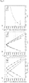
- Figure 2 shows the results of the parametric study for the gasification of coal (CH 0.6 O 0.02 ) for different temperatures (from 800 K to 1800 K).
- Figure 2a shows the molar amount of synthesis gas in dependency of the addition of oxygen.
- Figure 2b shows the synthesis gas ratio in dependency of the amount of oxygen.
- Figures 2c) and 2d show the molar amount of synthesis gas and the synthesis gas ratio respectively for different amounts of water as gasification agent.
- figures 2e) and 2f the influence of the addition of hydrogen is shown for the molar amount of synthesis gas and the synthesis gas ratio are shown.
- Figure 3 shows the results of the parametric study for the gasification of lignin (CH 1.1 O 0.4 ) for different temperatures (from 800 K to 1800 K).
- Figure 3a shows the molar amount of synthesis gas in dependency of the addition of oxygen.
- Figure 3b shows the synthesis gas ratio in dependency of the amount of oxygen.
- Figures 3c) and 3d show the molar amount of synthesis gas and the synthesis gas ratio for different amounts of water as gasification agent respectively.
- figures 3e) and 3f the influence of the addition of hydrogen is shown for the molar amount of synthesis gas and the synthesis gas ratio are shown.
- Figure 4 shows the results of the parametric study for the gasification of cellulose (CH 1.65 O 0.8 ) for different temperatures (from 800 K to 1800 K).
- Figure 4a shows the molar amount of synthesis gas in dependency of the addition of oxygen.
- Figure 4b shows the synthesis gas ratio in dependency of the amount of oxygen.
- Figures 4c) and 4d show the molar amount of synthesis gas and the synthesis gas ratio for different amounts of water as gasification agent respectively.
- figures 4e) and 4f the influence of the addition of hydrogen is shown for the molar amount of synthesis gas and the synthesis gas ratio are shown.
- Figures 5 show the molar amount of synthesis gas for gasification of coal (CH 0.6 O 0.02 ), lignin (CH 1.1 O 0.4 ) and cellulose (CH 1.65 O 0.8 ) at 1400 K.
- Figure 5a shows the molar amount of synthesis gas in dependency of the added oxygen amount.
- Figure 5b represents the synthesis gas amount versus the O:C-ratio of the operational composition.
- figure 5c the molar amount of synthesis gas is shown for different H:C-ratios at a constant O:C-ratio of 1.8. It is demonstrated that desired process criteria, i.e. the molar amount of synthesis gas, can be illustrated independent from the carbon-containing material (feedstock) using the plots in relation of O:C and H:C ratios.
- Figure 6 illustrates the determination of the borderlines in the O:C / H:C plot based on the process criteria and utilizing the non-stoichiometric equilibrium model.
- Figure 6a shows the borderlines resulting for molar amount of synthesis gas (>0.94; >0.80 and >0.70, corresponding to >94 %,>80 %; >70 %).
- Figure 6b shows the borderlines resulting for synthesis gas ratio (4.0, 3.0, 2.0 and 1.0).
- Figure 6c shows the borderlines resulting for solid carbon content ( ⁇ 0.1, ⁇ 0.01; ⁇ 0.001; corresponding to ⁇ 10 %, ⁇ 1 %; ⁇ 0.1 %).
- Figure 7 illustrates the determination of the operational window in the O:C / H:C plot based on the process criteria: molar amount of synthesis gas, synthesis gas ratio, and solid carbon content in synthesis gas.
- the process criteria applied are molar amount of synthesis gas of at least 70 % (>0.70), synthesis gas ratio from 1 to 2, and solid carbon content of equal or less than 1 % ( ⁇ 0.01).
- the operational window is the area denoted with +.
- Figure 8 illustrates the addition of water/steam (H2O), oxygen (O2) or carbon dioxide (CO2) starting from ash free (af) lignin in order to reach the operational window.
- H2O water/steam
- O2 oxygen
- CO2 carbon dioxide
- Figure 9 shows the results of the validation of the inventive method for conventional gasification.
- the results for the composition of the synthesis gas product (raw synthesis gas after gasification) described in literature (x-axis "Experiment") were compared with the results obtained via the non-stoichiometric equilibrium model for gasification (y-axis "Simulation”).
- the amounts of CO ( ⁇ ), CO 2 ( ⁇ ), H 2 ( ⁇ ) and CH 4 ( ) (given in vol.-% based on dry gases) in the raw synthesis gas are indicated.
- Figure 10 shows the results of the validation of the inventive method for plasma gasification.
- the results for the composition of the synthesis gas product (raw synthesis gas after gasification described in literature (x-axis "Experiment") were compared with the results obtained via the non-stoichiometric equilibrium model for gasification (y-axis "Simulation”).
- the amounts of CO( ⁇ ), CO 2 ( ⁇ ), H 2 ( ⁇ ) and N 2 ( ⁇ ) (given in vol.-% based on dry gases) in the raw synthesis gas product are indicated.
- the gasification agent was defined as being a oxygen, steam and/or carbon dioxide.
- k, I, p, x, y and m The definition of k, I, p, x, y and m was given as follows: Symbol Unit Addition in gasification agent O 2 k mol(O 2 )/mol(feedstock) H 2 O l mol(H 2 O)/mol(feedstock) CO 2 p mol(CO 2 )/mol(feedstock) Addition in feedstock C mol/mol(C in feedstock) H x mol(H)/mol(C in feedstock) O y mol(O)/mol(C in feedstock) Feedstock moisture H 2 O m mol(H 2 O)/mol(feedstock)
- thermodynamic data of the NIST-JANAF database was approximated by polynomial functions.
- thermodynamic data for water, carbon monoxide and carbon dioxide as given in tables S1 and S2 were used in the equilibrium model. The Gibbs free energy of formation for the elements was zero at all temperatures of interest. The pressure for all data was 0.1 MP.
- Table S1 Thermodynamic data for water, carbon monoxide and carbon dioxide ⁇ G°f [kJ/ mol] T [K] 800 1000 1200 1400 1600 1800 H 2 O -203.496 -192.59 -181.425 -170.089 -158.639 -147.111 CO -182.497 -200.275 -217.819 -235.149 -252.284 -269.242 CO2 -395.586 -395.886 -396.098 -396.24 -396.323 -396.353 a b c d e R 2 H2O 6.1907E-14 -9.1034E-10 4.9466E-06 0.047100 -243.570000 0.9999963 CO2 6.0815E-15 -7.
- Table S2 Coefficients for fit of the thermodynamic data shown in table S1.
- Figure 5a compares the obtainable molar amount of syngas for the three carbon-containing materials (feedstocks), i.e. coal, lignin, cellulose, and different amounts of oxygen added as gasification agent. For all feedstocks a maximum was observed, which shifted for the more functionalized feeds towards lower oxygen addition. This was caused by the different oxygen amount required to reach a stoichiometric O:C-ratio.
- the plot (see Figure 5b ) of the molar amount of synthesis gas versus the oxygen to carbon ratio of the operational composition (feedstock plus the gasification agent) provided a better comparison. It was found that the maximum was always at an O:C-ratio of one while the resulting curves showed similar characteristics.
- the inventive method provides a way to visualize an operational window of the gasification process. Therefore, desired process criteria set for the amount of synthesis gas (see figure 6a ), synthesis gas ratio (see figure 6b ), and as well as the solid carbon content (see figure 6c ), were added as borderlines to the van Krevelen plot based on the equilibrium calculation.
- the O:C- and H:C-ratio of the operational composition needed to be within this area.
- the proper use of gasification agents, drying or pre-wetting to achieve this operational composition can also be identified within the van Krevelen plot. It was demonstrated that the method provides the possibility to react on changes in feedstock composition and to tune the product gas composition through the flexible use of gasification agent.
- the process criteria were set as follows: molar amount of synthesis gas of at least 70 % (see borderlines in Figure 6a ), synthesis gas ratio from 1 to 2 (see borderlines in figure 6b ), and solid carbon content of equal or less than 1 % (see borderlines in figure 6c ).
- Figure 7 which can be regarded as a combination of figures 6a-6c , illustrates the determination of the operational window in the O:C / H:C plot based on the process criteria: molar amount of synthesis gas, synthesis gas ratio, and solid carbon content in synthesis gas.
- the three target variables (process criteria), molar amount of synthesis gas, synthesis gas ratio, and solid carbon content are illustrated as lines in the O:C / H:C plot in dependency of the operational composition.
- the operational window is denoted with +. It is revealed by requirements of a synthesis gas ratio greater than 1, a molar amount of synthesis gas of at least 70 % (indicated with lines > 0.70 in Figure and less than 1 % solid carbon.
- Figure 8 illustrates the addition of water/steam (H2O), oxygen (O2) or carbon dioxide (CO2) starting from ash free (af) lignin in order to reach the operational window. It is shown that it is possible to shift an operational composition (lignin, af) into the operational window in order to meet the defined requirements.
- the requirements reflected by the operational window are synthesis gas ratio greater than 1, a molar amount of synthesis gas of at least 70 % and a solid carbon content lower than 1 %.
- Lignin (af) is the moist, ash-free feedstock composition.
- the arrows represent possible shifts by adding the labelled gasification agent.
- a synthesis gas sum of at least 80 % and a carbon content of less than 1 % exclude a synthesis gas ratio of 2 and above as shown in Figure 7 .
Landscapes
- Chemical & Material Sciences (AREA)
- Engineering & Computer Science (AREA)
- Combustion & Propulsion (AREA)
- Oil, Petroleum & Natural Gas (AREA)
- Organic Chemistry (AREA)
- Organic Low-Molecular-Weight Compounds And Preparation Thereof (AREA)
Abstract
The present invention is directed to a method for determining process conditions for a process for synthesis gas production by gasification, in particular allothermic gasification, such as plasma gasification, of carbon-containing material using a gasification agent, wherein the composition of the gasification agent is determined based on the atomic ratios O:C and H:C of at least one operational composition, which is a mixture of the carbon-containing material and the gasification agent, and Furthermore, the invention is directed to the use of said method for process control, process monitoring, quality control, or process engineering of a process for synthesis gas production by gasification.
Description
- The present invention is directed to a method for determining process conditions for a process for synthesis gas production by gasification, in particular allothermic gasification, such as plasma gasification, of carbon-containing material using a gasification agent, wherein the composition of the gasification agent is determined based on the atomic ratios O:C and H:C of at least one operational composition, which is a mixture of the carbon-containing material and the gasification agent, and wherein the method utilizes a non-stoichiometric equilibrium model for gasification, in particular the non-stoichiometric equilibrium model is used for determining the synthesis gas product composition. Furthermore, the invention is directed to the use of said method for process control, process monitoring, quality control, or process engineering of a process for synthesis gas production by gasification.
- Gasification is commonly defined as thermochemical conversion of solid or liquid carbon-containing materials into a gaseous product, known as synthesis gas, which mainly consists of hydrogen (H2) and carbon monoxide (CO). The conversion takes place at high temperatures with the use of a gasification agent in an oxygen starving environment. Most commonly, air, pure oxygen, steam and combinations thereof are used as gasification agents in known gasification processes. Generally, the use of air introduces nitrogen (N2) in the product gases, thus considerably reducing the caloric value of the synthesis gas due to the dilution. Typically, the gasification process produces a gas phase and a solid residue (also referred to as char or ashes).
- Commonly known gasification reactor types are for example fixed-bed gasifiers (e.g. Lurgi gasifier), fluidized-bed gasifiers (e.g. Winkler generator) and entrained-flow gasifiers (e.g. entrained-flow gasifier of Koppers und Totzek).
- Gasification processes are typically differentiated in direct (or autothermic) and indirect (or allothermic) processes, wherein the energy required for the endothermic gasification process can be supplied directly in an autothermic process or indirectly in an allothermic process.
- Typically, in autothermic (direct) gasification a part of the carbon-containing raw material is combusted, e.g. in the same reaction chamber of the gasifier, in order to provide the necessary energy. Hence, directly operated gasifiers rely on the addition of oxygen or air and normally cannot work with pure carbon dioxide as gasification agent. Established direct gasification technologies, such as air or oxygen blown fixed bed, fluidized bed or entrained flow gasifiers, are typically operated in a range of about 800°C to 1400°C and use a gasification agent for conversion. Generally, the operation at high temperatures requires a burner, fuel, pipes and other installations. Required preheating of common gasifiers result in significant start-up times and are therefore only efficient when operated constantly over long-term period.
- Allothermic (indirect) gasification means that the energy required for the gasification process is supplied indirectly, for example via a heat exchanger or a circulating heat carrier. Another possibility is the gasification by means of plasma, such as microwave plasma or arc torch plasmas, which may be generated by an external power source. Plasma, as highly ionized gas, contains a significant number of electrically charged particles and is classified as the fourth state of matter. As plasma contains an equal number of free positive and negative charges, it is electrically neutral. Plasma processes may be largely classified into thermal and non-thermal hot plasma processes.
- Plasma gasification of carbon-containing feedstock material using thermal plasma and arc torch plasmas are for example described in
WO 2012/39751 A2 US 2010/0199557 A1 . Further, the use of microwave plasma in biomass gasification is described inWO 2018/187741 . - Furthermore, so called power-to-X concepts (or also referred to as power-to-value), e.g. power-to-synthesis gas, allows the use of renewably generated electricity and safe energy supply. Further, waste-to-energy (WtE) concepts utilize the thermal energy of waste materials, e.g. by conversion as heat or convert the combustibles to electricity in a power plant. So called waste to-X (WtX) (also referred to as waste-to-value) concepts allow the use of waste materials as raw material for the production of chemicals, e.g. synthesis gas.
- Common gasification technologies convert fossil raw materials, such as coal, to synthesis gas. However, with regard to the global changing raw material situation, the interest in utilization of alternatives to fossil materials is increasing, such as biomass, as CO2-neutral energy and raw material, as well as waste materials. For example typical carbon-containing raw materials used as feedstock for gasification, for both power generation or production of chemicals, are coal, biomass, and waste materials. Typically, known gasification technologies are dedicated to specific raw material and narrow particle size distribution as well as low moisture content, increasing pretreatment costs and complexity.
- Typically, the synthesis gas product of gasification processes is used for generating power or for producing chemicals wherein the latter requires the production of chemical grade synthesis gas. For example downstream processes for producing chemicals are catalytic synthesis reactions, such as methanol synthesis, mixed alcohol synthesis, Fischer-Tropsch synthesis, oxo-synthesis or methanation. As a rule, synthesis gas for use in downstream catalytic synthesis reactions (also referred to as chemical grade synthesis gas) requires a high ratio of H2 to CO of about 2:1. Therefore, normally the ratio of H2 to CO is adjusted via so called water-gas shift reaction downstream the gasification reaction. In the water-gas shift reaction the synthesis gas is brought in contact with steam, wherein the carbon monoxide reacts with steam according to CO + H2O → CO2 + H2 (water-gas shift reaction, WGSR).
- Often the synthesis gas product contains impurities besides carbon monoxide (CO) and hydrogen (H2), such as tars, volatile or semi-volatile organic compounds, sulfur compounds, ammonia, nitrogen oxides, sulfur oxides, hydrogen chloride and ashes. Typically, the production of chemical grade synthesis gas for use in downstream catalytic synthesis reactions requires the removal of such impurities and purification steps. High levels of impurities require cost-intense synthesis gas clean-up for further processing.
- Most of the gasification processes described in the state of the art, such as gasification processes for power generation as well as for the production of chemicals, are operated directly and as a consequence require the addition of pure oxygen or air.
- A process for using biomass or waste to produce conversion products, such as synthesis gas for value-added products, is still challenging because of the above mentioned draw-backs of gasification technologies and the variations in bio-based raw material quality. Typically, the processes and plants are designed for a specific raw material.
- Thus, there is a need to provide suitable or optimized process conditions for integrated synthesis gas production, such as power-to-value or waste-to-value processes, that allows high process feedstock flexibility, so that the process can be easily adapted in view of different carbon-containing starting materials. In particular high process feedstock flexibility means that the process is efficient and flexible towards change in feedstock composition, feedstock quality, feedstock quantity, particle size and moisture content. In particular the inventive method should allow determination of process conditions for a gasification process that should allow the flexible allothermic conversion of waste materials into synthesis gas.
- In summary there is a need for simulation studies working also in the temperature regime relevant for plasma gasification. Furthermore, in light of the waste-to-value concept it is of interest to study the resulting synthesis gas composition, despite the caloric value. Here, minimal separation effort especially for tar and oil fractions as also a synthesis gas ratio (H2/CO ratio) close to later applications (e.g. about 2 for Methanol and Fischer-Tropsch-Synthesis) are aimed for. Furthermore, in view of process tolerance, it is of interest how feedstock pre-treatment and gasification agent can be applied to react to feed composition changes.
- One object of the present invention is to provide a method for determining suitable or preferably optimized process conditions for gasification, in particular for plasma gasification, that meet the above mentioned need and overcomes the drawbacks of the state of the art. In particular one object of the invention is to provide a gasification process, that is easy to implement and that uses readily available apparatus.
- It has been surprisingly found that the object as described above can be solved by the inventive method. Particularly, it has been found that a thermodynamic equilibrium model can advantageously be used to study the capability of plasma gasification, in particular in waste-to-value concepts and to optimize the achievable total amount of synthesis gas and the synthesis gas ratio. It was found that optimal process conditions, such as temperature and gasification agent composition, can be found based on thermodynamic equilibrium modelling, wherein it is possible to react on changes in feedstock composition and to tune the product gas composition through the flexible use of gasification agent. Furthermore, a way to visualize an operational window of the gasification process is presented. Therefore, constraints set for the synthesis gas ratio and amount as well as the solid carbon content are added based on the equilibrium calculation as borderlines to the O:C / H:C plot. Such O:C / H:C plots are commonly known and also referred to as van Krevelen plot (van Krevelen, D.W., 1957. Coal science: aspects of coal constitution. Elsevier Publishing Company, Amsterdam).
- In particular it has been found that desired process criteria can be reliably and easily adjusted for different carbon-containing feedstock materials via the adjustment of the composition of the gasification agent, wherein the gasification agent is preferably selected from carbon dioxide, steam, oxygen, hydrogen, methane, air and mixtures thereof.
- The present invention is directed to a method for determining process conditions, in particular suitable or optimized process conditions, for a process for synthesis gas production by gasification, in particular plasma gasification, of carbon-containing material using a gasification agent, which comprises at least one gas selected from carbon dioxide, steam, oxygen, hydrogen, methane and air, wherein the composition of the gasification agent is determined based on the atomic ratios O:C and H:C of at least one operational composition, which is a mixture of the carbon-containing material and the gasification agent, and wherein the method utilizes a non-stoichiometric equilibrium model for gasification.
- Generally, the inventive method allows easily adjusting relevant process parameters according to the given feedstock material and depending on arbitrary desired process criteria, for example specifications in view of the yield of synthesis gas, water content in synthesis gas, solid carbon content in the synthesis gas, etc.
- In particular, the inventive method allows the use of different carbon-containing material, wherein the desired synthesis gas ratio and synthesis gas yield can be obtained by the adjustment of the composition of the gasification agent. Thus, the process conditions for indirect (allothermic) gasification process can flexibly be used for different carbon-containing raw materials without the need of changes in the technical equipment. Further different operating conditions, such as the omission of oxygen, can be utilized in the gasification process.
- Further, the inventive method allows to evaluate the suitability of a given carbon-containing feedstock material for a gasification process, in particular a plasma gasification process, having defined process criteria.
- Further, the inventive method allows controlling a process for the indirect (allothermic) gasification of a carbon-containing feedstock material based on given process criteria.
- In terms of the present invention synthesis gas means a gas mixture comprising (or preferably essentially consisting of) hydrogen and carbon monoxide. In particular synthesis gas exhibits a molar ratio of hydrogen to carbon monoxide in the range of 1:1 to 2.5:1. In term of the present invention the molar ratio of hydrogen to carbon monoxide (H2/CO) is referred to as synthesis gas ratio.
- In terms of the present invention an allothermic processes, in particular an allothermic gasification (or also indirect gasification), means that the required energy for the endothermic gasification process is at least partly supplied indirectly as external energy. In particular at least 10 % of the required energy is supplied via external energy.
- In terms of the present invention steam means water in the gaseous state.
- In particular the inventive method encompasses the definition of the composition of at least carbon-containing material composition or a group of such compositions (also referred to as an starting window) defined by atomic O:C and H:C ratios within the O:C / H:C plot (also known as van-Krevelen-plot).
- In particular determining the composition of the gasification agent is carried out by the following step:
- defining the suitable combinations of carbon-containing material compositions within the starting window and operational compositions within the operational window, wherein the operational compositions are reached starting from the carbon-containing material compositions by the addition of at least one gas selected from carbon dioxide, steam, oxygen, hydrogen, methane, and air, within the O:C / H:C plot.
- Optionally, preferred combinations as defined above may be selected based on the non-stoichiometric equilibrium model for gasification.
- In a preferred embodiment the method for determining process conditions for a process for synthesis gas production comprises the following steps:
- i) defining the composition of at least one carbon-containing material or a group of such compositions (starting window) within the O:C / H:C plot;
- ii) defining at least one operational composition or group of operational compositions (operational window) within the O:C / H:C plot based on the non-stoichiometric equilibrium model for gasification, and preferably based on at least one process criterion, selected from molar amount of synthesis gas, synthesis gas ratio, solid carbon content in the synthesis gas, carbon dioxide emission, and water content in the synthesis gas product;
- iii) defining at least one suitable combination of carbon-containing material composition (within the starting window) and operational composition (within the operational window), wherein the operational composition is reached within the O:C / H:C plot starting from the carbon-containing material compositions by the addition of at least one gas selected from carbon dioxide, steam, oxygen, hydrogen, methane, and air;
- iv) determining at least one suitable composition of the gasification agent based on the suitable combination(s) obtained in step iii).
- In a preferred embodiment the gasification is an allothermic gasification, wherein external energy obtained from electric power, preferably from electric power generated by renewable energy, is supplied in the gasification step. More preferably, the gasification is an arc-plasma gasification.
- Preferably, the gasification includes supplying external energy obtained from electric power, wherein the external energy causes the gasification reaction of the carbon-containing material, in the presence of the gasification agent.
- The present invention is directed to a method for determining process conditions, e.g. optimal process conditions, for a process for synthesis gas production by gasification, wherein the composition of the gasification agent is determined based on the atomic ratios O:C and H:C of at least one operational composition. In particular process conditions are understood as being process parameters that are set using the inventive method in order to obtain optimal or desired process results, such as one or more of the process criteria as described below. According to the present invention the composition of the gasification agent is determined as one process condition.
- Furthermore, it is possible to determining additional process conditions, in particular optimized process conditions, for the synthesis gas production process via the inventive method, such as gasification temperature and water content of the carbon-containing material.
- Typically, the composition of the gasification agent is given by the molar fraction (given in mol%) for at least one gas selected from carbon dioxide, steam, oxygen, hydrogen, methane and air, or ranges thereof.
- It has been found that above 1400 K the temperature has only a minor influence on relevant process criteria and a temperature invariant product composition can be achieved for a given feedstock. This allows for a stable and tolerant operation regime, in which particular suitable synthesis gas ratios and low solid carbon contents can be obtained within the ratio of O:C and H:C of the chosen operational window. Preferably, the method for determining process conditions is directed to a process for synthesis gas production via plasma gasification which is carried out at a temperature above 1400 K, preferably in range of 1,400 to 1,800 K, in the gasification step.
- Typically, the synthesis gas (also referred to as syngas) produced via the gasification process comprises hydrogen and carbon monoxide, wherein the sum of hydrogen and carbon monoxide in the produced synthesis gas is from 80 to 100 mol%, typically 80 to 95 mol%, based on the total synthesis gas, and calculated without inert gases, such as nitrogen.
- Often the synthesis gas produced in the gasification of carbon-containing material may comprise further components besides hydrogen and carbon monoxide, such as common impurities and/or inert components. Typically, such further components may be present up to 1000 ppm. In particular the synthesis gas may comprise one or more further components besides hydrogen (H2) and carbon monoxide (CO) selected from carbon dioxide (CO2), methane (CH4), steam, nitrogen (N2), noble gases (e.g. argon), other nitrogen compounds, such as nitrogen oxides (NOx), ammonia (NH3), and hydrogen cyanide (HCN); sulfur compounds, e.g. hydrogen sulfide (H2S), sulfur dioxide (SO2), carbonyl sulfide (COS), carbon disulfide (CS2), methane thiol (CH3SH), thiophene, benzothiophene and/or halogen compounds, such as hydrogen chloride (HCI). Typically, such gaseous impurities in the synthesis gas may be selected from nitrogen (N2), ammonia (NH3), hydrogen cyanide (HCN), and hydrogen chloride (HCl).
- Preferably, the content of solid carbon in the synthesis gas product is less than 1 % (mol%), preferably from 0.1 to 0.8 % (mol%).
- In a preferred embodiment the method is directed to the production of chemical grade synthesis gas. In particular chemical grade synthesis gas exhibits a composition and content of impurities in such way that it can be used for typical downstream processes, such as methanol synthesis, mixed alcohol synthesis, Fischer-Tropsch synthesis, oxo-synthesis (also referred to as hydroformylation), and methanation.
- Preferably, the synthesis gas has a synthesis gas ratio in the range of 1:1 to 2.5:1, preferably in the range of 1.5:1 to 2.1:1. Preferably, the composition of the synthesis gas, e.g. the hydrogen to carbon monoxide ratio, may be varied in view of the requirements of the specific downstream process. In particular the synthesis gas is used in a methanol synthesis process and has synthesis gas ratio in the range of 2.0 : 1 to 2.5 : 1. In particular the synthesis gas is used in a Fischer-Tropsch process and has synthesis gas ratio in the range 1.5 : 1 to 2.5 : 1, preferably 2.0 : 1 to 2.5 : 1.
- In particular the inventive method encompasses the definition of the composition of least one carbon-containing material or a group of such compositions (also referred to as an starting window) defined by atomic O:C and H:C ratios within the O:C / H:C plot (also known as van-Krevelen plot or Krevelen plot).
- In particular the process for synthesis gas production by gasification comprises feeding a feedstock, comprising at least one carbon-containing material, and a gasification agent into a gasifier. Typically, the feedstock (or also referred to as feedstock material) consists of the one or more carbon-containing material(s) as described in the following.
- In a preferred embodiment the carbon-containing material is a mixture of different carbon-containing materials as described in the following, for example a mixture of different waste materials. In particular the composition of the carbon-containing material based on the atomic ratios O:C and H:C, e.g. within the range of CH0.0-2.2O0.0-1.3, can be adjusted via mixing of different carbon-containing materials. In particular the starting window within the O:C / H:C plot can be defined via the mixture of different carbon-containing materials.
- Furthermore, it is possible to use an unknown carbon-containing material, wherein the composition of said unknown carbon-containing material based on the atomic ratios O:C and H:C is determined via ultimate analysis and said composition (e.g. ratios O:C and H:C) is used in the inventive method.
- Furthermore, it is possible to use an unknown carbon-containing material, wherein the carbon-containing material, e.g. a plastic waste material, is characterized by a known analysis method, e.g. ultimate analysis, infrared spectroscopy, and the composition of said unknown carbon-containing material is defined based on the results of the said analysis method and the atomic ratios O:C and H:C commonly known and/or described in literature.
- In particular the carbon-containing material used in the inventive method for determining process conditions for a process for synthesis gas production are selected from materials comprising carbon, hydrocarbons or mixtures thereof.
- In a preferred embodiment the carbon-containing material is selected from coal, biomass (e.g. wood or straw), cellulose-containing materials, lignin-containing materials, hydrocarbons, organic matter, waste material, such as municipal waste (e.g. municipal solid waste MSW), plastic solid waste materials (PSW), non-recyclable waste materials (e.g. thermographic paper), waste materials from chemical industry processes (e.g. solvents or residues) (referred to as chemical process waste materials), sludges, rubbers, and mixtures thereof.
- In a preferred embodiment the carbon-containing material is selected from coal, cellulose-containing materials, and lignin-containing materials, more preferably from coal, lignin and cellulose.
- In particular the carbon-containing material has a composition in the range defined by CH0.0-2.2O0.0-1.3.
- Preferably, the carbon-containing material used in the inventive method for determining process conditions is selected from coal, preferably having a composition CH0.0-0.9O0.0-01; lignin, preferably having a composition CH0.6-1.6O0.0-0.9; and cellulose, preferably having a composition CH1.0-2.2O0.3-1.3. More preferably the carbon-containing material can be selected from coal, having a composition CH0.6O0.02; lignin having a composition CH1.1O0.4; and cellulose, having a composition CH1.65O0.8.
- Preferably, the inventive method is directed to a process for synthesis gas production which is utilized as waste-to-value (WtV) process, wherein the value is for example synthesis gas or a downstream product, e.g. methanol, Fischer-Tropsch waxes, Fischer-Tropsch fuels, alcohols (from mixed alcohol synthesis), aldehydes (from hydroformylation) or methane (from methanation). Thus, in a preferred embodiment the carbon-containing material is selected from waste materials comprising hydrocarbons, in particular selected from agricultural waste, industrial organic waste, industrial biogenic waste, and municipal waste.
- In a preferred embodiment, the carbon-containing material is selected from one or more plastic solid waste (PSW) materials. Preferably, the carbon-containing material is selected from non-recyclable waste materials (e.g. thermographic paper).
- In particular the inventive method is directed to a process of the allothermic gasification of plastic solid waste (PSW). In particular the composition of the gasification agent can be adjusted in view of the used plastic solid waste material and/or the desired synthesis gas ratio in the produced synthesis gas.
- Plastic solid waste (PSW) is for example selected from automotive shredder residue (ASR), post-consumer plastic waste, household plastic waste, commercial plastic waste.
- Often plastic solid waste is a mixture of commonly used plastic materials. Preferably the plastic solid waste comprises one or more plastic materials selected from styrene polymers (e.g. GPPS, HIPS), styrene copolymers (e.g. ABS, ASA), polyesters (e.g. PBT, PET), polyvinylchloride (PVC), polyolefins (e.g. PE, PP, HDPE, LDPE, LLDPE), polyether ether ketone (PEEK), polyvinylacetate (PVA), polyurethane (PU), polyamides (e.g. PA6), acrylate polymers (e.g. PMMA), polyvinyl chloride (PVC), polyvinylidene fluoride (PVDF), polycarbonate (PC), polyoxomethylene (POM).
- Preferably the plastic solid waste (PSW) comprises (preferably consists of) one or more plastic materials selected from polystyrene (PS), general purpose polystyrene (GPPS), high impact polystyrene (HIPS), polybutylene terephthalate (PBT), polyethylene terephthalate (PET), polyethylene (PE), polypropylene (PP), polyether ether ketone (PEEK), and polyvinyl acetate (PVA). More preferably the plastic solid waste (PSW) comprises (preferably consists of) one or more plastic materials selected from polyethylene (PE), polypropylene (PP), polystyrene (PS) and polyether ether ketone (PEEK).
- In a preferred embodiment the carbon-containing material comprises only one of the above mentioned plastic materials (single-sort recycled PSW). In another preferred embodiment the carbon-containing material comprises two or more of the above mentioned plastic materials (mixed-sort recycled PSW).
- In a preferred embodiment the carbon-containing material, in particular PSW, exhibits an atomic ratio of O:C (oxygen to carbon) in the range of 0.0 to 0.7; preferably in the range of 0.0 to 0.1; and/or an atomic ratio H:C (hydrogen to carbon) in the range of 0.4 to 2.2; preferably in the range of 1.8 to 2.2. Preferably, the carbon-containing material has a composition CH0.4-2.2O0.0-0.7; more preferably a composition CH1.8-22O0.0-01. More preferably, the carbon-containing material is at least one plastic solid waste having a composition in the range defined by CH0.4-2.2O0.0-0.7; more preferably CH1.8-2.2O0.0-01.
- Typically, the carbon-containing material may be pretreated before fed into the gasifier. For example the feedstock comprising at least one carbon-containing material is dried before feeding into the gasifier. For example the feedstock comprising at least one carbon-containing material may be reduced to small particles, e.g. by cutting, crushing, grinding. Further, the pretreatment may encompasses separating and sorting of the feedstock material.
- Typically, the carbon-containing material has a water content of up to 50 % by weight, preferably up to 30 % by weight, preferably in the range of 0 to 50 % by weight, preferably 0.001 to 40 % by weight. Preferably, the carbon-containing material is selected from plastic solid waste material and has a water content of up to 5 % by weight, preferably up to 1 % by weight, more preferably in the range of about 0 to 1 % by weight.
- According to the inventive method, the gasification agent comprises at least one gas selected from carbon dioxide, steam, oxygen, hydrogen, methane, and air, preferably selected from carbon dioxide, steam, oxygen, hydrogen and methane; more preferably selected from carbon dioxide, steam, hydrogen, and methane, also preferably from oxygen, carbon dioxide, and steam. Often the gasification agent is a mixture of two or more of the gases mentioned before.
- In a preferred embodiment the gasification agent comprises (preferably consists of):
- 0 to 98 mol%, preferably 5 to 80 mol%, more preferably 10 to 60 mol%, of carbon dioxide;
- 1 to 98 mol%, preferably 5 to 80 mol%, more preferably 10 to 60 mol%, of steam;
- 1 to 98 mol%; preferably 5 to 80 mol%, more preferably 10 to 60 mol%, of oxygen;
- 0 to 97 mol%, preferably 0 to 85 mol%, more preferably 0 to 70 mol%, of hydrogen;
- 0 to 97 mol%, preferably 0 to 85 mol%, more preferably 0 to 70 mol%, of methane; and
- 0 to 5 mol%, preferably 0 to 2 mol%, more preferably 0 to 1 mol%, of further components, preferably further gaseous components, e.g. selected from carbon monoxide and gaseous impurities, e.g. impurities comprising sulfur compounds and/or nitrogen compounds.
- Typically, the gasification agent may comprise impurities, in particular gaseous impurities, in the ppb or ppm range, for example in the amount of 0.001 ppm to 100 ppm. Typically, such impurities are selected from sulfur compounds, nitrogen compounds and halogen compounds as mentioned above in connection with the synthesis gas impurities.
- Further, the gasification agent may comprise carbon monoxide in an amount of from 0 to 30 mol%, preferably of from 0.0001 to 10 mol%.
- In an embodiment the gasification agent comprises less than 1 mol%, preferably less than 0.1 mol%, of nitrogen.
- Preferably, the gasification agent may comprise methane obtained from bio gas production.
- Typically, the inventive method encompasses the definition of at least one operational composition, which is a mixture of the carbon-containing material and the gasification agent, based on the atomic ratios O:C and H:C within the O:C / H:C plot (also known as van-Krevelen-plot). Preferably, the inventive method encompasses the definition of a group of operational compositions (also referred to as an operational window) defined by atomic O:C and H:C ratios, preferably represented as a box within the O:C / H:C plot.
- In a preferred embodiment the operational composition or operational window is defined based on criteria set for relevant process parameter (also referred to as process criteria in the following). Said process criteria described in the following are for example synthesis gas ratio, yield of synthesis gas, carbon efficiency, and solid carbon content in the synthesis gas.
- Preferably, the operational composition or operational window is defined using the non-stoichiometric equilibrium model for gasification. It is also possible to use a simulation based on said non-stoichiometric equilibrium model for gasification. In particular, the operational composition or operational window is defined based on said non-stoichiometric equilibrium model for gasification, wherein one or more process parameters as described below are set as constraints on the synthesis gas composition (product gas composition) calculated by the non-stoichiometric equilibrium model for gasification.
- Preferably, the at least one operational composition, or preferably the operational window, is defined based on the non-stoichiometric equilibrium model for gasification and is defined based on at least one process criterion, selected from molar fraction of synthesis gas (yield of synthesis gas), synthesis gas ratio, solid carbon content in the synthesis gas, carbon efficiency (yield of carbon monoxide), carbon dioxide emission, and water content in the synthesis gas product.
- In a preferred embodiment the operational composition is at least one composition selected from compositions having an atomic ratio of O:C in the range of 1.0 to 1.7; preferably in the range of 1.2 to 1.5; and/or an atomic ratio H:C in the range of 2.0 to 4.0; preferably in the range of 3.0 to 3.4. Preferably, the operational composition is at least one composition selected from the range defined by CH2.0-4.0O1.0-1.7; more preferably CH2.7-3.7O1.1-1.6, also preferably CH3.0-3.4O1.2-1.5, most preferably the operational composition is CH3.2O1.4. Also preferably, the operational window has an atomic ratio of O:C in the range of 1.0 to 1.7; preferably in the range of 1.2 to 1.5; and/or an atomic ratio H:C in the range of 2.0 to 4.0; preferably in the range of 3.0 to 3.4. Preferably, the operational window is CH2.0-4.0O1.0-1.7; more preferably CH2.7-3.7O1.1-1.6, also preferably CH3.0-3.4O1.2-1.5.
- In another preferred embodiment the operational composition is at least one composition selected from compositions having an atomic ratio of O:C in the range of 1.1 to 1.4 and/or an atomic ratio H:C in the range of 2.0 to 4.0. Preferably, the operational composition is at least one composition selected from CH2.0-4.0O1.1-1.4. Also preferably the operational window has an atomic ratio of O:C in the range of 1.1 to 1.4 and/or an atomic ratio H:C in the range of 2.0 to 4.0. Preferably, the operational composition is at least one composition selected from CH2.0-4.0O1.1-1.4.
- It has been found that these preferred operational compositions or operational windows can advantageously be used in a gasification process (preferably plasma gasification process). Further, it has been found that these preferred operational compositions or operational windows can advantageously be used in a gasification process (preferably plasma gasification process) at a gasification temperature of above 1400 K.
- The process criteria as described in the following may be used to define at least one suitable operational composition or preferably an operational window (i.e. the group of suitable or preferred operational compositions) within the O:C / H:C plot based on the non-stoichiometric equilibrium model for gasification.
- Preferably, the process criterion used in the inventive method is one or more selected from molar amount of synthesis gas (yield of synthesis gas), synthesis gas ratio, solid carbon content in the synthesis gas product, carbon efficiency (yield of carbon monoxide), carbon dioxide emission, and water content in the synthesis gas product; more preferably selected from molar fraction of synthesis gas (yield of synthesis gas) and synthesis gas ratio. Typically, two or more, preferably 2-5, more preferably 2-3 process criteria are used in the inventive method in order to define the operational composition(s) or the operational window.
- In particular the molar fraction of synthesis gas (Y(syngas)) in % is given by:

- Typically, the molar amounts are given as molar flow in a continuous process. Preferably, the inventive method is based on maximum molar amount of synthesis gas as relevant process criteria. Preferably, a molar amount of synthesis gas of at least 70 %, preferably at least 80 %, preferably in the range of 70 to 100 %, more preferably 80 to 95 %, is used as process criterion in the inventive method.
- In particular the synthesis gas ratio (r(syngas)) is given by:

- Typically, the molar amounts are given as molar flow in a continuous process. Preferably, a synthesis gas ratio in the range of 1:1 to 2.5:1, preferably 1.1:1 to 2.5:1, more preferably 1.5:1 to 2.5:1, more preferably 2:1 to 2.1:1, also preferably 1:1 to 2:1, most preferably 2:1, is used as process criterion in the inventive method.
- In particular the solid carbon content (SCC) in the synthesis gas is given in % by:

- Typically, the molar amounts are given as molar flow in a continuous process. Preferably, the inventive method is based on minimum solid carbon content in the synthesis gas as one relevant process criteria. Preferably, solid carbon content (SCC) of below 1 %, preferably in the range of 0 to 0.9 %, more preferably 0.1 to 0.8 %, is used as process criterion in the inventive method.
- In particular the carbon efficiency (yield of carbon monoxide, Y(CO)) in % is given by:

- Typically, the molar amounts are given as molar flow in a continuous process. Preferably, the inventive method is based on maximum carbon efficiency as relevant process criteria. Preferably, a carbon efficiency of at least 60 %, preferably at least 80 %, preferably in the range of 60 to 100 %, more preferably 80 to 95 %, is used as process criterion in the inventive method.
- The invention method for determining process conditions for synthesis gas production by gasification utilizes a non-stoichiometric equilibrium model for gasification. In particular the non-stoichiometric equilibrium model is utilized for determining the synthesis gas product composition.
- Typically, the utilization of the non-stoichiometric equilibrium model includes the solution of a system of equations as described below, resulting from minimization of the total Gibbs free energy. In particular the non-stoichiometric equilibrium model for gasification may be implemented in the inventive method via generally known computer programs including the possibility for solving systems of nonlinear algebraic equations, e.g. Matlab, Mathematica and Microsoft Excel Solver add-in.
- Further, the inventive method can for example be based on a simulation which is based on said non-stoichiometric equilibrium model for gasification. Typically, suitable simulation methods are known in the art and are carried out using commonly known computer programs, for example Aspen One® simulation software (from Aspen Technology, Inc., US).
- Generally, in the non-stoichiometric equilibrium model employed in the inventive method, the equilibrium composition of a system, comprising (preferably consisting of) the desired product species, is calculated by minimization of the total Gibbs free energy of the system Gs, wherein the total Gibbs free energy of the system Gs is defined as:

- ni
- is the amount of substance of considered product species i;
- N
- is the number of considered product species; and
- µi
- is the chemical potential of considered product species i.
- Preferably, the chemical potential µi of species i, which are considered as ideal gases, is given by:

- ΔG°f,i
- is the standard Gibbs free energy of formation of the species i;
- R
- is the ideal gas constant;
- T
- is the temperature of the species or of the system;
- ni
- is the amount of substance of product species i; and
- ntotal
- is the total amount of substance of all N product species considered.
- Preferably, two or more, preferably all, product species, selected from solid carbon (C (s)), gaseous carbon monoxide (CO (g)), gaseous carbon dioxide (CO2(g)), gaseous methane (CH4 (g)), gaseous hydrogen (H2 (g)), and gaseous water (steam, H2O (g)) are considered.
- Preferably, the non-stoichiometric equilibrium model of the inventive method includes the calculation of the equilibrium composition of a system, comprising the considered product species, by minimization of the total Gibbs free energy of the system Gs, wherein the objective function of the minimization problem (minimization of Gs) is given by formula (3):

- Preferably, the inventive method may include the calculation of the equilibrium composition as described for different temperatures T within a given range, more preferably for a temperature range of from 800 to 1,800 K.
- Preferably, the is the standard Gibbs free energies of formation of the considered species (ΔG°f,i) and their temperature dependence are determined based on standard databases, e.g. NIST-JANAF database. Typically, the standard Gibbs free energies of formation of the considered species (ΔG°f,i) at the given temperature can be approximated by polynomial functions given in said standard data bases.
- Preferably, said minimization problem, preferably the minimization problem given by formula (3), is solved using the constraint represented by the mass balance of each element (in particular C, H, O) according to formula (4):

wherein - Aj
- is the total number of atoms of the j-th element (in particular C, H, O), present in the reaction mixture,
- ai,j
- is the number of atoms of element j in product species i;
- ni
- is the amount of substance of product species i, and
- N
- is the number of considered product species.
- Preferably, the mass balances according to formula (4) of the elements C (carbon), H (hydrogen) and O (oxygen) are considered as constraints for the calculation of the synthesis gas product composition by the non-stoichiometric equilibrium model.
- Typically, the input species needs to be specified in order to determine available atoms Aj for the non-stoichiometric equilibrium model. In particular, the input of feedstock (carbon-containing material), feedstock moisture and gasification agents are considered in the model, e.g. in the mass balances of formula (4).
- Typically, the gasification agents considered in the non-stoichiometric equilibrium model for gasification are as described above. In particular at least oxygen, steam and carbon dioxide are considered.
- Typically, the feedstock (carbon-containing material) is given in form of a carbon-normalized composition CHxOy . For example such normalized composition CHxOy is calculated according to the following formulas (5) and (6):


- Wdry
- is the weight fractions on dry basis; and
- M
- is the molar mass.
- Typically, the production of synthesis gas by gasification encompasses process steps including the gasification reaction carried out in a gasifier, and typically additional pretreatment steps and/or subsequent steps of purification or the so called water gas shift.
- Preferably, the method for determining process conditions is directed to a process for synthesis gas production by gasification comprising the steps:
- a) feeding a feedstock, comprising at least one carbon-containing material, and a gasification agent, comprising at least one gas, selected from carbon dioxide, steam, oxygen, hydrogen, methane and air, as feed stream into a gasifier, wherein a product stream comprising raw synthesis gas is generated;
- b) removing the raw synthesis gas as product stream from the gasifier and optionally cooling the product stream;
- c) separating the solid ingredients from the gaseous ingredients in the raw synthesis gas product stream;
- d) feeding the product stream obtained in step c) into a water-gas shift reactor, wherein a part of the carbon monoxide of the synthesis gas is transformed together with steam into hydrogen and carbon dioxide and wherein a modified synthesis gas product stream is obtained;
- e) optionally removing sulfur compounds from the modified product stream in a desulfurizing step;
- f) removing and separating carbon dioxide at least partially from the modified product stream obtained in step d) or e), wherein an exhaust gas comprising carbon dioxide and a separated synthesis gas product stream are obtained;
- g) optionally further purification of the separated synthesis gas product stream obtained in step f).
- For example, the synthesis gas product stream obtained in step f) or g) can be used in a downstream synthesis process, wherein at least one downstream synthesis product and an exhaust gas comprising carbon dioxide is obtained.
- Typically, the at least one carbon-containing material used as feedstock may be in solid and/or liquid form. In a preferred embodiment the carbon-containing material used as feedstock in the gasification process of the inventive method is in solid form.
- In a preferred embodiment the gasification is carried out as an allothermic gasification, wherein external energy is supplied in the gasification step a), preferably external energy obtained from electric power, more preferably external energy obtained from electric power generated by renewable energy. For example the renewable energy for generating the electric power is based on biomass, hydroelectricity, wind power, geothermal energy, or solar energy (e.g. photovoltaic electricity, solar thermal power, concentrated solar power).
- In a preferred embodiment the external energy is supplied in the gasifier in step a) in form of a plasma, preferably an arc plasma. In this preferred embodiment the inventive method is directed to the production of synthesis gas by plasma gasification of carbon-containing material. The utilization of plasma as external power source can be advantageous due to higher flexibility as the external power source can be adapted depending on the carbon containing raw material and the process conditions.
- Generally, a plasma is defined as an ionized gas, which contains a significant number of electrically charged particles (ions and electrons) and is classified as the fourth state of matter. Typically, a plasma is electrically conductive and it is electrically neutral, as plasma contains an equal number of free positive and negative charges. The degree of ionization can typically be less than 1 % or up to 100 %. Typically, a plasma can be generated by suppling external energy, e.g. in form of thermal energy, strong electro-magnetic fields, into a gas in the ground state.
- Generally, the plasma used in gasification step a) may be a non-thermal plasma or a thermal plasma. Typically, a non-thermal plasma or also referred to as non-equilibrium plasma is a plasma that is not in a thermodynamic equilibrium due to the different temperature of the different particle species (electrons and heavy species, i.e. neutrals, ions). Generally, a thermal plasma or also referred to as equilibrium plasma is a plasma that is in a thermodynamic equilibrium due to the same temperature of the different particle species.
- More preferably the gasification is carried out in step a) using a plasma as external energy and at a temperature in the range of 1,400 K to 1,800 K.
- Preferably, the plasma used the gasification of the inventive method may be generated by using various commonly known methods, such as by using an arc plasma torch, gliding arc discharge, a plasma pencil, a plasma needle, a plasma jet, a dielectric barrier discharge, a resistive barrier discharge, a piezoelectric direct discharge, a glow discharge or a microwave plasma generation.
- In a preferred embodiment the external energy is supplied in form of an arc plasma in the gasification step a). Arc plasma (electrical arc plasma) is defined as a plasma generated in an electrical arc, via electrical discharge and ionization of a gas.
- In a preferred embodiment the external energy is supplied in form of an arc plasma in the gasification step a). Arc plasma (electrical arc plasma) is defined as a plasma generated in an electrical arc, via electrical discharge and ionization of a gas. Generally, plasma torches for arc plasma generation are commonly known by a skilled person (e.g. from Westinghouse Plasma Corporation). For example the external energy is supplied in the gasifier in step a) in form of plasma, preferably an arc plasma generated by a plasma torch operated in the power range of 80 to 4000 kW, preferably 300 to 3000 kW.
- Preferably the gasification in step a) is carried out at a temperature in the range of 500 K to 2,000 K, preferably from 500 to 1,800 K, more preferably from 700 to 1,600 K (operational temperature).
- In a preferred embodiment the gasification is carried out at a temperature in the range of 1,200 K to 2,000 K, preferably of 1,300 K to 1,800 K, wherein the external energy is supplied in the gasifier in step a) in form of a plasma, preferably an arc plasma. It has been found that the plasma gasification process is less temperature sensitive at a gasification temperature at 1400 K or above, resulting in improved process tolerance. In a preferred embodiment the gasification is carried out at a temperature above 1,400 K, preferably in the range of 1,400 to 1,800 K, wherein the external energy is supplied in the gasifier in step a) in form of a plasma, preferably an arc plasma.
- The temperature given above for the gasification in step a) is directed to the gas temperature of the product stream leaving the gasifier in step a) said temperature can also be referred to as operational temperature in gasification step a). Typically, the core temperature of the plasma can be more than 2,000 K, for example the core temperature of the plasma can be in the range of 5,000 to 50,000 K in an arc plasma.
- For example the gasification reaction in step a) can be carried out using commonly known types of gasifiers, for examples fluidized-bed gasifiers, fixed-bed gasifiers or entrained-flow gasifiers or combinations thereof.
- In a preferred embodiment the raw synthesis gas obtained in the gasification step a) exhibits a synthesis gas ratio (molar H2/CO) in the range of 1 : 1 to 2.1 : 1, preferably 1 : 1 to 1.5 : 1.
- Suitable subsequent steps are commonly known and described in the state of the art, such as separation of the solid ingredients in the raw synthesis gas product stream which is removed from the gasifier from the gaseous ingredients, e.g. by means of cyclones, filters (e.g. moving bed filters, ceramic filter candles), electrostatic filters (ESP), and (solvent) scrubbers.
- Typically, raw synthesis gas obtained in the gasification step is fed into a water-gas shift reactor, optionally together with steam, wherein a part of the carbon monoxide of the synthesis gas is transformed together with steam into hydrogen and carbon dioxide according to the water-gas shift reaction according to CO + H2O → CO2 + H2, and wherein a modified synthesis gas product stream is obtained.
- Generally, the process of water-gas shift reaction and apparatus therefore are commonly known and described in the state of the art, e.g. Ullmann's Encyclopedia of Industrial Chemistry, Wiley-VCH, 2011, Vol. 16, p. 483-493, Gas Production, 3. Gas Treating, Boll et al.
- Typically, sulfur compounds, such as hydrogen sulfide (H2S) and/or carbonyl sulfide (COS), are removed at least partially from the modified synthesis gas product stream. Typically, other impurities, such as HCI and CO2, may be removed at least partially in such desulfurizing step as well. Typically, such desulfurizing step can be carried out using known wet and/or dry processes as known in the state of the art.
- Generally, such adsorption and adsorption processes are known by a skilled person and described in the state of the art, e.g. Ullmann's Encyclopedia of Industrial Chemistry, Wiley-VCH, 2011, Vol. 16, p. 498-535, Gas Production, 3. Gas Treating, Boll et al.
- Typically, the gasification process encompasses removing and separating the carbon dioxide at least partially from the modified synthesis gas product stream, wherein an exhaust gas comprising carbon dioxide may be obtained. Typically, carbon dioxide can be removed from the synthesis gas product stream by chemical and physical absorption with at least one liquid solvent or by adsorption with at least one solid adsorbent. Suitable processes are described in the state of the art, such as Thermal Swing Adsorption (TSA) or Pressure Swing Adsorption (PSA).
- Often, further purification of the synthesis gas product stream may be necessary to fulfill the requirements for chemical grade synthesis gas that can be used in a downstream synthesis reaction, in particular a catalytic downstream synthesis reaction. Typically, such further purification includes the removal or reduction of contaminants, such as chlorine compounds (e.g. hydrogen chloride HCI), nitrogen compounds (e.g. NH3, HCN), sulfur compounds (e.g. H2S, COS, SOx), water, alkali and earth alkali compounds. For example such purification may be carried out by wet scrubbing or by dry adsorption processes, e.g. by adsorption to a solid adsorbent, in particular zinc oxide (ZnO) or iron oxid (FeO).
- Typically, the synthesis gas can be used as an intermediate product in a downstream synthesis process for the production of downstream products (i.e. secondary products of synthesis gas), such as methanol, Fischer-Tropsch waxes, Fischer-Tropsch fuels, alcohols (from mixed alcohol synthesis), aldehydes (from hydroformylation) or methane (from methanation), preferably methanol.
- Generally, such downstream synthesis process using synthesis gas are commonly known and described in the state of the art, such as the relevant chapters in Ullmann's Encyclopedia of Industrial Chemistry (for example Ullmann's Encyclopedia of Industrial Chemistry, Wiley VCH, 2011, Vol. 6 Bierhals, Carbon Monoxide, p. 679-693, e.g. p. 689, https://doi.org/10.1002/14356007.a05_203). In particular the synthesis of methanol by using synthesis gas is for example described in Ullmann's Encyclopedia of Industrial Chemistry, Wiley VCH, 2012, Ott et al., Methanol, p. 1-27, https://doi.org/10.1002/14356007.a16_465.pub3). For example the synthesis of carbon hydrogens via Fischer-Tropsch synthesis is described in Ullmann's Encyclopedia of Industrial Chemistry, Wiley VCH, 2011, Chapter 4, de Klerk, Fischer-Tropsch Synthesis, https://doi.org/10.1002/9783527635603.ch4). For example the production of aldehydes from alkenes using synthesis gas via oxo synthesis (also known as oxo process or hydroformylation) is described in Ullmann's Encyclopedia of Industrial Chemistry, Wiley VCH, 2013, Bahrmann et al., Oxo Synthesis, p. 1-8, https://doi.org/10.1002/14356007.a18_321.pub2).
- Furthermore, the invention is directed to the use of the method for determining process condition as described above for process control for synthesis gas production by gasification, process monitoring of a process for synthesis gas production by gasification, quality control of a process for synthesis gas production by gasification, evaluation of carbon-containing material for a process for synthesis gas production by gasification, adaption of process conditions for a process for synthesis gas production by gasification depending on variation of carbon-containing material (feedstock material), process engineering for a process for synthesis gas production by gasification.
- Generally, the inventive method can be used for adjusting the composition of the gasification agent, based on a given feedstock material (carbon-containing material). Further, inventive method can be used for adjusting the composition of the gasification agent depending on arbitrary desired process criteria, for example specifications in view of the yield of synthesis gas, water content in synthesis gas, solid carbon content in the synthesis gas, etc. The use of the inventive method can for example be directed to process monitoring, quality control of the synthesis gas product, and process engineering.
- In particular, the inventive method allows to evaluate the suitability of a given carbon-containing feedstock material for a gasification process (in particular a plasma gasification process), for example based on defined process criteria.
- The inventive method can also be used for unknown carbon-containing material based on results of ultimate analysis or for mixtures of different carbon containing materials.
- Preferably, the inventive method allows controlling and/or engineering a process for the indirect (allothermic) gasification of a carbon-containing feedstock material based on given process criteria.
-
Figure 1 shows the O:C / H:C plot including compositions of suitable carbon-containing feedstock materials and illustrates the change by addition of gasification agent, i.e. CH4, H2O, O2, CO2. The carbon-containing feedstock materials are dry-ash-free coal ("Coal, daf"); dry-ash-free lignin ("Lignin, daf"); dry-ash-free cellulose ("Cellulose, daf"); and ash-free lignin ("Lignin, af"). Typically, said plot shows the variety of feedstock compositions and illustrates the shift in the O:C / H:C plot by adding different gasification agent. -
Figure 2 shows the results of the parametric study for the gasification of coal (CH0.6O0.02) for different temperatures (from 800 K to 1800 K).Figure 2a ) shows the molar amount of synthesis gas in dependency of the addition of oxygen.Figure 2b ) shows the synthesis gas ratio in dependency of the amount of oxygen.Figures 2c) and 2d ) show the molar amount of synthesis gas and the synthesis gas ratio respectively for different amounts of water as gasification agent. Infigures 2e) and 2f ) the influence of the addition of hydrogen is shown for the molar amount of synthesis gas and the synthesis gas ratio are shown. -
Figure 3 shows the results of the parametric study for the gasification of lignin (CH1.1O0.4) for different temperatures (from 800 K to 1800 K).Figure 3a ) shows the molar amount of synthesis gas in dependency of the addition of oxygen.Figure 3b ) shows the synthesis gas ratio in dependency of the amount of oxygen.Figures 3c) and 3d ) show the molar amount of synthesis gas and the synthesis gas ratio for different amounts of water as gasification agent respectively. Infigures 3e) and 3f ) the influence of the addition of hydrogen is shown for the molar amount of synthesis gas and the synthesis gas ratio are shown. -
Figure 4 shows the results of the parametric study for the gasification of cellulose (CH1.65O0.8) for different temperatures (from 800 K to 1800 K).Figure 4a ) shows the molar amount of synthesis gas in dependency of the addition of oxygen.Figure 4b ) shows the synthesis gas ratio in dependency of the amount of oxygen.Figures 4c) and 4d ) show the molar amount of synthesis gas and the synthesis gas ratio for different amounts of water as gasification agent respectively. Infigures 4e) and 4f ) the influence of the addition of hydrogen is shown for the molar amount of synthesis gas and the synthesis gas ratio are shown. -
Figures 5 show the molar amount of synthesis gas for gasification of coal (CH0.6O0.02), lignin (CH1.1O0.4) and cellulose (CH1.65O0.8) at 1400 K.Figure 5a ) shows the molar amount of synthesis gas in dependency of the added oxygen amount.Figure 5b ) represents the synthesis gas amount versus the O:C-ratio of the operational composition. Infigure 5c ) the molar amount of synthesis gas is shown for different H:C-ratios at a constant O:C-ratio of 1.8. It is demonstrated that desired process criteria, i.e. the molar amount of synthesis gas, can be illustrated independent from the carbon-containing material (feedstock) using the plots in relation of O:C and H:C ratios. -
Figure 6 illustrates the determination of the borderlines in the O:C / H:C plot based on the process criteria and utilizing the non-stoichiometric equilibrium model.Figure 6a shows the borderlines resulting for molar amount of synthesis gas (>0.94; >0.80 and >0.70, corresponding to >94 %,>80 %; >70 %).Figure 6b shows the borderlines resulting for synthesis gas ratio (4.0, 3.0, 2.0 and 1.0).Figure 6c shows the borderlines resulting for solid carbon content (<0.1, <0.01; <0.001; corresponding to <10 %, <1 %; <0.1 %). -
Figure 7 illustrates the determination of the operational window in the O:C / H:C plot based on the process criteria: molar amount of synthesis gas, synthesis gas ratio, and solid carbon content in synthesis gas. The process criteria applied are molar amount of synthesis gas of at least 70 % (>0.70), synthesis gas ratio from 1 to 2, and solid carbon content of equal or less than 1 % (<0.01). The operational window is the area denoted with +. -
Figure 8 illustrates the addition of water/steam (H2O), oxygen (O2) or carbon dioxide (CO2) starting from ash free (af) lignin in order to reach the operational window. -
Figure 9 shows the results of the validation of the inventive method for conventional gasification. The results for the composition of the synthesis gas product (raw synthesis gas after gasification) described in literature (x-axis "Experiment") were compared with the results obtained via the non-stoichiometric equilibrium model for gasification (y-axis "Simulation"). The amounts of CO (■), CO2(●), H2(▲) and CH4() (given in vol.-% based on dry gases) in the raw synthesis gas are indicated.
-
Figure 10 shows the results of the validation of the inventive method for plasma gasification. The results for the composition of the synthesis gas product (raw synthesis gas after gasification described in literature (x-axis "Experiment") were compared with the results obtained via the non-stoichiometric equilibrium model for gasification (y-axis "Simulation"). The amounts of CO(■), CO2(●), H2(▲) and N2(★) (given in vol.-% based on dry gases) in the raw synthesis gas product are indicated. - The following examples are intended to illustrate the subject matter of the invention without restricting it thereto.
- The following carbon containing materials were used in order to set the range of atomic ratio H:C and O:C:
- coal represented by the model composition CH0.6O0.02
- lignin represented by the model composition of CH1.1O0.4
- cellulose represented by the model composition of CH1.65O0.8
- The gasification agent was defined as being a oxygen, steam and/or carbon dioxide.
- The following compounds were considered in the non-stoichiometric equilibrium model for gasification as product species obtained in the gasification step (main products and by-products):
- Carbon, C(s)
- Carbon monoxide, CO (g)
- Carbon dioxide, CO2 (g)
- Methane, CH4 (g)
- Hydrogen, H2 (g)
- Steam, H2O (g)
- The following process criteria were used as constrains for defining the operational window:
- molar amount of synthesis gas of at least 70 %
- synthesis gas ratio in the range of 1:1 to 2:1
- solid carbon content (SCC) in the synthesis gas below 1 %
- Combining the constrains resulting from all these three process criteria in one single O:C / H:C plot (see
Figure 3 ) revealed an operational window, where all of these requisites are fulfilled, as roughly defined as: - H:C-ratio from 2 to 4 and O:C-ratio from 1.2 to 1.5
- Several process conditions, such as composition of gasification agent and gasification temperature were evaluated based on the O:C / H:C plot and the non-stoichiometric equilibrium model for gasification as described in the following.
- The defined minimization problem consisting of the objective function (3)


- The definition of k, I, p, x, y and m was given as follows:
Symbol Unit Addition in gasification agent O2 k mol(O2)/mol(feedstock) H2O l mol(H2O)/mol(feedstock) CO2 p mol(CO2)/mol(feedstock) Addition in feedstock C mol/mol(C in feedstock) H x mol(H)/mol(C in feedstock) O y mol(O)/mol(C in feedstock) Feedstock moisture H2O m mol(H2O)/mol(feedstock) - The symbols of formulas (1), and (7) to (9) have the following meaning:
- A:
- Total number of atoms of one element, e.g. Ac is the total number of carbon atoms
- Gs:
- Total Gibbs free energy of the system in J
- ΔG°f,i:
- Standard Gibbs free Energy of formation of the i-th molecule in J/mol
- n:
- Amount of substance in mol
- R:
- Ideal gas constant in J/(mol·K)
- T:
- Temperature in Kelvin
- The values of the standard Gibbs free energy of formation of product species and their temperature dependence were taken from the NIST-JANAF database. The pressure was constant at 0.1 MPa in all simulations. For the calculation of ΔG°f,i at a desired temperature T, the thermodynamic data of the NIST-JANAF database was approximated by polynomial functions.
- The following thermodynamic data for water, carbon monoxide and carbon dioxide as given in tables S1 and S2 were used in the equilibrium model. The Gibbs free energy of formation for the elements was zero at all temperatures of interest. The pressure for all data was 0.1 MP.
Table S1: Thermodynamic data for water, carbon monoxide and carbon dioxide ΔG°f [kJ/ mol] T [K] 800 1000 1200 1400 1600 1800 H2O -203.496 -192.59 -181.425 -170.089 -158.639 -147.111 CO -182.497 -200.275 -217.819 -235.149 -252.284 -269.242 CO2 -395.586 -395.886 -396.098 -396.24 -396.323 -396.353 a b c d e R2 H2O 6.1907E-14 -9.1034E-10 4.9466E-06 0.047100 -243.570000 0.9999963 CO2 6.0815E-15 -7.6509E-11 -1.0401E-06 -0.003221 -393.570000 0.9999277 CO 1.3312E-14 -2.6969E-10 3.2782E-06 -0.093932 -109.340000 0.9999999 - Table S2: Coefficients for fit of the thermodynamic data shown in table S1. The used equation is

- The influence of temperature, O2 addition, H2O addition and H2 addition in the gasification of coal, lignin and cellulose (as described under Ia.) in view of molar amount of synthesis gas, synthesis gas ratio, and solid carbon content were determined based on the non-stoichiometric equilibrium model for gasification as described above.
- The results are represented in the
figures 2 ,3 and4 . The influences on the molar amount of synthesis gas and on the synthesis gas ratio are shown for different gasification temperatures. - It was found, that above 1,400 K the temperature has only a minor influence and a temperature invariant product composition can be achieved for a given feedstock. Thus, a gasification process above 1,400 K allows for a stable and tolerant operation regime and gives rise to high process tolerance. Within this regime suitable process criteria, such as synthesis gas ratio and low solid carbon contents, can be combined if the proper ratio of O:C and H:C is chosen. The stable regime at high temperatures corroborated the possible advantage of plasma gasification, where higher temperatures, above 1,400 K, were accessible.
-
Figure 5a compares the obtainable molar amount of syngas for the three carbon-containing materials (feedstocks), i.e. coal, lignin, cellulose, and different amounts of oxygen added as gasification agent. For all feedstocks a maximum was observed, which shifted for the more functionalized feeds towards lower oxygen addition. This was caused by the different oxygen amount required to reach a stoichiometric O:C-ratio. The plot (seeFigure 5b ) of the molar amount of synthesis gas versus the oxygen to carbon ratio of the operational composition (feedstock plus the gasification agent) provided a better comparison. It was found that the maximum was always at an O:C-ratio of one while the resulting curves showed similar characteristics. The observed slight differences at lower and higher O:C-ratios seemed to be caused due to the different hydrogen to carbon ratio of the different feedstocks, as illustrated inFigure 5c . A further addition of hydrogen as gasification agent could fully compensate the H:C feedstock difference. In total, this demonstrated how a similar product spectrum can result through the flexible use of gasification agents, despite employing different feedstock compositions. Thus, it was possible to determine the process tolerance towards feed variations. - The inventive method provides a way to visualize an operational window of the gasification process. Therefore, desired process criteria set for the amount of synthesis gas (see
figure 6a ), synthesis gas ratio (seefigure 6b ), and as well as the solid carbon content (seefigure 6c ), were added as borderlines to the van Krevelen plot based on the equilibrium calculation. The area defined by all overlaying borderlines, defined the operational windows of the process (seefigure 7 ). The O:C- and H:C-ratio of the operational composition needed to be within this area. Depending on the O:C- and H:C-ratio of the feedstock the proper use of gasification agents, drying or pre-wetting to achieve this operational composition can also be identified within the van Krevelen plot. It was demonstrated that the method provides the possibility to react on changes in feedstock composition and to tune the product gas composition through the flexible use of gasification agent. - The process criteria were set as follows: molar amount of synthesis gas of at least 70 % (see borderlines in
Figure 6a ), synthesis gas ratio from 1 to 2 (see borderlines infigure 6b ), and solid carbon content of equal or less than 1 % (see borderlines infigure 6c ). -
Figure 7 , which can be regarded as a combination offigures 6a-6c , illustrates the determination of the operational window in the O:C / H:C plot based on the process criteria: molar amount of synthesis gas, synthesis gas ratio, and solid carbon content in synthesis gas. The three target variables (process criteria), molar amount of synthesis gas, synthesis gas ratio, and solid carbon content are illustrated as lines in the O:C / H:C plot in dependency of the operational composition. The operational window is denoted with +. It is revealed by requirements of a synthesis gas ratio greater than 1, a molar amount of synthesis gas of at least 70 % (indicated with lines > 0.70 in Figure and less than 1 % solid carbon. -
Figure 8 illustrates the addition of water/steam (H2O), oxygen (O2) or carbon dioxide (CO2) starting from ash free (af) lignin in order to reach the operational window. It is shown that it is possible to shift an operational composition (lignin, af) into the operational window in order to meet the defined requirements. The requirements reflected by the operational window are synthesis gas ratio greater than 1, a molar amount of synthesis gas of at least 70 % and a solid carbon content lower than 1 %. Lignin (af) is the moist, ash-free feedstock composition. The arrows represent possible shifts by adding the labelled gasification agent. - This approach of plotting borderlines for the process criteria within the van Krevelen diagram allows identifing excluding combinations very fast. For instance, a synthesis gas sum of at least 80 % and a carbon content of less than 1 % exclude a synthesis gas ratio of 2 and above as shown in
Figure 7 . - The results of the inventive method for determining process conditions for different carbon-containing materials were compared with experimental results obtained from literature:
- The results for the composition of the synthesis gas product described in literature for conventional gasification ("Experiment") were compared with the results obtained via the non-stoichiometric equilibrium model for gasification ("Simulation"). The amounts of CO, CO2, H2 and CH4 (given in vol.-% based on dry gases) in the raw synthesis gas product stream were compared.
Figure 9 shows the results of the validation of the inventive method for conventional gasification. - The results for the composition of the synthesis gas product described in literature for plasma gasification ("Experiment") were compared with the results obtained via the non-stoichiometric equilibrium model for gasification ("Simulation"). The amounts of CO, CO2, H2 and N2 (given in vol.-% based on dry gases) in the raw synthesis gas product stream were compared.
Figure 10 shows the results of the validation of the inventive method for plasma gasification. Most of the values are within the deviation of ± 20 % from the line y=x.
Claims (15)
- Method for determining process conditions for a process for synthesis gas production by gasification of carbon-containing material using a gasification agent, which comprises at least one gas selected from carbon dioxide, steam, oxygen, hydrogen, methane and air, wherein the composition of the gasification agent is determined based on the atomic ratios O:C and H:C of at least one operational composition, which is a mixture of the carbon-containing material and the gasification agent, and wherein the method utilizes a non-stoichiometric equilibrium model for gasification.
- Method for determining process conditions according to claim 1, wherein the method comprises the following steps:i) defining the composition of at least one carbon-containing material or a group of such compositions (starting window) within the O:C / H:C plot;ii) defining at least one operational composition or group of operational compositions (operational window) within the O:C / H:C plot based on the non-stoichiometric equilibrium model for gasification;iii) defining at least one suitable combination of carbon-containing material composition and operational composition, wherein the operational composition is reached within the O:C / H:C plot starting from the carbon-containing material composition by the addition of at least one gas selected from carbon dioxide, steam, oxygen, hydrogen, methane, and air;iv) determining at least one suitable composition of the gasification agent based on the suitable combination(s) obtained in step iii).
- Method for determining process conditions according to claim 1 or 2, wherein the at least one operational composition is defined based on the non-stoichiometric equilibrium model for gasification and is defined based on at least one process criterion, selected from molar fraction of synthesis gas, synthesis gas ratio, solid carbon content in the synthesis gas, carbon efficiency, carbon dioxide emission, and water content in the synthesis gas product.
- Method for determining process conditions according to claim 3, wherein a molar amount of synthesis gas of at least 70 % is used as process criterion.
- Method for determining process conditions according to claim 3 or 4, wherein a synthesis gas ratio in the range of 1.1:1 to 2.5:1 is used as process criterion.
- Method for determining process conditions according to any of claims 1 to 5, wherein the gasification is an allothermic gasification, wherein external energy obtained from electric power is supplied in the gasification step.
- Method for determining process conditions according to any of claims 1 to 6, wherein the gasification is an arc-plasma gasification.
- Method for determining process conditions according to any of claims 1 to 7, wherein the carbon-containing material has a composition in the range defined by CH0.0-2.2O0.0-1.3.
- Method for determining process conditions according to any of claims 1 to 8, wherein the carbon-containing material is at least one plastic solid waste having a composition in the range defined by CH0.4-2.2O0.0-0.7.
- Method for determining process conditions according to any of claims 1 to 9, wherein the composition of the carbon-containing material based on the atomic ratios O:C and H:C is adjusted via mixing of different carbon-containing materials.
- Method for determining process conditions according to any of claims 1 to 10, wherein the operational composition is at least one composition selected from the range defined by CH2.0-4.0O1.0-1.7.
- Method for determining process conditions according to any of claims 1 to 11, wherein the method is directed to a process for synthesis gas production via plasma gasification, which is carried out at a temperature above 1400 K in the gasification step.
- Method for determining process conditions according to any of claims 1 to 12, wherein the gasification agent comprises at least one gas selected from carbon dioxide steam, hydrogen and methane.
- Method for determining process conditions according to any of claims 1 to 13, wherein the non-stoichiometric equilibrium model of the inventive method includes the calculation of the equilibrium composition of a system, comprising the considered product species, by minimization of the total Gibbs free energy of the system Gs, wherein the objective function of the minimization problem is given by formula (3):
 ΔG°f,i is the standard Gibbs free energy of formation of the species i;R is the ideal gas constant;T is the temperature of the system;ni is amount of substance of product species i; andntotal is the total amount of substance of moles of all N product species considered.
 - Use of a method for determining process condition according to any of claim 1 to 14 for process control for synthesis gas production by gasification, process monitoring of a process for synthesis gas production by gasification, quality control of a process for synthesis gas production by gasification, evaluation of carbon-containing material for a process for synthesis gas production by gasification, adaption of process conditions for a process for synthesis gas production by gasification depending on variation of carbon-containing material, process engineering for a process for synthesis gas production by gasification.
Priority Applications (2)
| Application Number | Priority Date | Filing Date | Title |
|---|---|---|---|
| EP20163007.6A EP3878927A1 (en) | 2020-03-13 | 2020-03-13 | Method for determining optimal process conditions for a process for synthesis gas production by gasification |
| PCT/EP2021/054725 WO2021180483A1 (en) | 2020-03-13 | 2021-02-25 | Method for determining optimized process conditions for a process for synthesis gas production by gasification |
Applications Claiming Priority (1)
| Application Number | Priority Date | Filing Date | Title |
|---|---|---|---|
| EP20163007.6A EP3878927A1 (en) | 2020-03-13 | 2020-03-13 | Method for determining optimal process conditions for a process for synthesis gas production by gasification |
Publications (1)
| Publication Number | Publication Date |
|---|---|
| EP3878927A1 true EP3878927A1 (en) | 2021-09-15 |
Family
ID=69844491
Family Applications (1)
| Application Number | Title | Priority Date | Filing Date |
|---|---|---|---|
| EP20163007.6A Withdrawn EP3878927A1 (en) | 2020-03-13 | 2020-03-13 | Method for determining optimal process conditions for a process for synthesis gas production by gasification |
Country Status (1)
| Country | Link |
|---|---|
| EP (1) | EP3878927A1 (en) |
Cited By (1)
| Publication number | Priority date | Publication date | Assignee | Title |
|---|---|---|---|---|
| CN119989934A (en) * | 2025-04-11 | 2025-05-13 | 山西盛德汇嘉工程技术有限公司 | A control method and system for energy engineering digital intelligence platform based on multi-source data fusion |
Citations (3)
| Publication number | Priority date | Publication date | Assignee | Title |
|---|---|---|---|---|
| US20100199557A1 (en) | 2009-02-11 | 2010-08-12 | Dighe Shyam V | Plasma gasification reactor |
| WO2012039751A2 (en) | 2010-09-24 | 2012-03-29 | James Charles Juranitch | Renewable combined cycle low turbine boost |
| WO2018187741A1 (en) | 2017-04-07 | 2018-10-11 | Sundrop Fuels, Inc. | Multi-purpose application of the second stage of a 2-stage bio-reforming reactor system for reforming bio-syngas natural gas and process recycle streams |
-
2020
- 2020-03-13 EP EP20163007.6A patent/EP3878927A1/en not_active Withdrawn
Patent Citations (3)
| Publication number | Priority date | Publication date | Assignee | Title |
|---|---|---|---|---|
| US20100199557A1 (en) | 2009-02-11 | 2010-08-12 | Dighe Shyam V | Plasma gasification reactor |
| WO2012039751A2 (en) | 2010-09-24 | 2012-03-29 | James Charles Juranitch | Renewable combined cycle low turbine boost |
| WO2018187741A1 (en) | 2017-04-07 | 2018-10-11 | Sundrop Fuels, Inc. | Multi-purpose application of the second stage of a 2-stage bio-reforming reactor system for reforming bio-syngas natural gas and process recycle streams |
Non-Patent Citations (6)
| Title |
|---|
| BAHRMANN ET AL.: "Ullmann's Encyclopedia of Industrial Chemistry", vol. 16, 2013, WILEY VCH, article "Gas Production, 3. Gas Treating", pages: 679 - 693 |
| CHANGQING DONG ET AL: "Exergy evaluation of the biomass gasification system for varied fuel type", SUSTAINABLE POWER GENERATION AND SUPPLY, 2009. SUPERGEN '09. INTERNATIONAL CONFERENCE ON, IEEE, PISCATAWAY, NJ, USA, 6 April 2009 (2009-04-06), pages 1 - 6, XP031608550, ISBN: 978-1-4244-4934-7, DOI: 10.1109/SUPERGEN.2009.5348067 * |
| NGUBEVANA L ET AL: "Introducing novel graphical techniques to assess gasification", ENERGY CONVERSION AND MANAGEMENT, ELSEVIER SCIENCE PUBLISHERS, OXFORD, GB, vol. 52, no. 1, 1 January 2011 (2011-01-01), pages 547 - 563, XP027443521, ISSN: 0196-8904, [retrieved on 20101023], DOI: 10.1016/J.ENCONMAN.2010.07.030 * |
| P. PRABIR: "BIOMASS GASIFICATION AND PYROLYSIS: PRACTICAL DESIGN", BIOMASS GASIFICATION AND PYROLYSIS: PRACTICAL DESIGN, 31 December 2010 (2010-12-31), pages 119 - 120, XP055190610 * |
| PRIYO ADI SESOTYO ET AL: "Plasma gasification modeling of municipal solid waste from Jatibarang Landfill in Semarang, Indonesia: analyzing its performance parameters for energy potential", E3S WEB OF CONFERENCES, vol. 125, 1 January 2019 (2019-01-01), pages 14009, XP055733234, DOI: 10.1051/e3sconf/201912514009 * |
| VAN KREVELEN, D.W.: "Coal science: aspects of coal constitution", 1957, ELSEVIER PUBLISHING COMPANY |
Cited By (1)
| Publication number | Priority date | Publication date | Assignee | Title |
|---|---|---|---|---|
| CN119989934A (en) * | 2025-04-11 | 2025-05-13 | 山西盛德汇嘉工程技术有限公司 | A control method and system for energy engineering digital intelligence platform based on multi-source data fusion |
Similar Documents
| Publication | Publication Date | Title |
|---|---|---|
| Tungalag et al. | Yield prediction of MSW gasification including minor species through ASPEN plus simulation | |
| Tavares et al. | A theoretical study on municipal solid waste plasma gasification | |
| Yoon et al. | Hydrogen-rich syngas production through coal and charcoal gasification using microwave steam and air plasma torch | |
| Materazzi et al. | Performance analysis of RDF gasification in a two stage fluidized bed–plasma process | |
| US12129439B2 (en) | Process for the manufacture of a useful product from waste materials and/or biomass | |
| Striūgas et al. | Investigation of sewage sludge treatment using air plasma assisted gasification | |
| Pan et al. | Fluidized-bed co-gasification of residual biomass/poor coal blends for fuel gas production | |
| Okati et al. | Parametric studies over a plasma co-gasification process of biomass and coal through a restricted model in Aspen plus | |
| WO2021180482A1 (en) | Process for the production of synthesis gas by gasification with controlled carbon dioxide reduction | |
| US20140196368A1 (en) | Gasifier having at least one charge transfer electrode and methods of use thereof | |
| Straka et al. | Hydrogen-rich gas as a product of two-stage co-gasification of lignite/waste plastics mixtures | |
| Serrano et al. | Waste tyres valorisation through gasification in a bubbling fluidised bed: An exhaustive gas composition analysis | |
| EP2915869A1 (en) | Entrained bed gasifier with integrated medium temperature plasma | |
| Bosmans et al. | Waste-to-clean syngas: avoiding tar problems | |
| Cvetinović et al. | Thermal plasma gasification of sewage sludge: Optimisation of operating parameters and economic evaluation | |
| WO2021180483A1 (en) | Method for determining optimized process conditions for a process for synthesis gas production by gasification | |
| Yang et al. | Gasification applicability study of polyurethane solid refuse fuel fabricated from electric waste by measuring syngas and nitrogenous pollutant gases | |
| Acar et al. | Simulation of biomass gasification process using aspen plus | |
| Yousef et al. | Steam‑oxygen Gasification of Surgical Mask Waste in an Updraft Fixed Bed Gasifier System and Its Life-cycle Assessment | |
| Harouna et al. | Experimental study of the co‐gasification of wood and polyethylene in a two‐stage gasifier | |
| Zhao et al. | Experimental and simulated analysis for nitrogen migration behavior during coal rapid pyrolysis under Ar/CO2 atmospheres using a free-fall reactor | |
| Khumalo et al. | Synergistic Effects of Biomass-polyethylene Co-gasification: A Simulation Approach | |
| Ismail et al. | Empty fruit bunch (EFB) gasification in an entrained flow gasification system | |
| Čespiva et al. | Evaluation of the suitability of defined SRF in mixture with wood and as a standalone fuel for the pilot-scale gasification processes | |
| Kombe | Thermodynamic modelling and optimization of biomass gasification system for fischer-tropsch synthesis |
Legal Events
| Date | Code | Title | Description |
|---|---|---|---|
| PUAI | Public reference made under article 153(3) epc to a published international application that has entered the european phase |
Free format text: ORIGINAL CODE: 0009012 |
|
| STAA | Information on the status of an ep patent application or granted ep patent |
Free format text: STATUS: THE APPLICATION HAS BEEN PUBLISHED |
|
| AK | Designated contracting states |
Kind code of ref document: A1 Designated state(s): AL AT BE BG CH CY CZ DE DK EE ES FI FR GB GR HR HU IE IS IT LI LT LU LV MC MK MT NL NO PL PT RO RS SE SI SK SM TR |
|
| STAA | Information on the status of an ep patent application or granted ep patent |
Free format text: STATUS: THE APPLICATION IS DEEMED TO BE WITHDRAWN |
|
| 18D | Application deemed to be withdrawn |
Effective date: 20220316 |