EP3878739A1 - Bidirectional aircraft rotor - Google Patents
Bidirectional aircraft rotor Download PDFInfo
- Publication number
- EP3878739A1 EP3878739A1 EP21167220.9A EP21167220A EP3878739A1 EP 3878739 A1 EP3878739 A1 EP 3878739A1 EP 21167220 A EP21167220 A EP 21167220A EP 3878739 A1 EP3878739 A1 EP 3878739A1
- Authority
- EP
- European Patent Office
- Prior art keywords
- tail rotor
- tail
- rotor blade
- bidirectional
- rotor system
- Prior art date
- Legal status (The legal status is an assumption and is not a legal conclusion. Google has not performed a legal analysis and makes no representation as to the accuracy of the status listed.)
- Granted
Links
Images


Classifications
-
- B—PERFORMING OPERATIONS; TRANSPORTING
- B64—AIRCRAFT; AVIATION; COSMONAUTICS
- B64C—AEROPLANES; HELICOPTERS
- B64C27/00—Rotorcraft; Rotors peculiar thereto
- B64C27/82—Rotorcraft; Rotors peculiar thereto characterised by the provision of an auxiliary rotor or fluid-jet device for counter-balancing lifting rotor torque or changing direction of rotorcraft
-
- B—PERFORMING OPERATIONS; TRANSPORTING
- B64—AIRCRAFT; AVIATION; COSMONAUTICS
- B64C—AEROPLANES; HELICOPTERS
- B64C27/00—Rotorcraft; Rotors peculiar thereto
- B64C27/32—Rotors
- B64C27/46—Blades
-
- B—PERFORMING OPERATIONS; TRANSPORTING
- B64—AIRCRAFT; AVIATION; COSMONAUTICS
- B64C—AEROPLANES; HELICOPTERS
- B64C27/00—Rotorcraft; Rotors peculiar thereto
- B64C27/32—Rotors
- B64C27/46—Blades
- B64C27/467—Aerodynamic features
-
- B—PERFORMING OPERATIONS; TRANSPORTING
- B64—AIRCRAFT; AVIATION; COSMONAUTICS
- B64C—AEROPLANES; HELICOPTERS
- B64C27/00—Rotorcraft; Rotors peculiar thereto
- B64C27/82—Rotorcraft; Rotors peculiar thereto characterised by the provision of an auxiliary rotor or fluid-jet device for counter-balancing lifting rotor torque or changing direction of rotorcraft
- B64C2027/8209—Electrically driven tail rotors
-
- B—PERFORMING OPERATIONS; TRANSPORTING
- B64—AIRCRAFT; AVIATION; COSMONAUTICS
- B64C—AEROPLANES; HELICOPTERS
- B64C27/00—Rotorcraft; Rotors peculiar thereto
- B64C27/82—Rotorcraft; Rotors peculiar thereto characterised by the provision of an auxiliary rotor or fluid-jet device for counter-balancing lifting rotor torque or changing direction of rotorcraft
- B64C2027/8227—Rotorcraft; Rotors peculiar thereto characterised by the provision of an auxiliary rotor or fluid-jet device for counter-balancing lifting rotor torque or changing direction of rotorcraft comprising more than one rotor
-
- B—PERFORMING OPERATIONS; TRANSPORTING
- B64—AIRCRAFT; AVIATION; COSMONAUTICS
- B64C—AEROPLANES; HELICOPTERS
- B64C27/00—Rotorcraft; Rotors peculiar thereto
- B64C27/82—Rotorcraft; Rotors peculiar thereto characterised by the provision of an auxiliary rotor or fluid-jet device for counter-balancing lifting rotor torque or changing direction of rotorcraft
- B64C2027/8254—Shrouded tail rotors, e.g. "Fenestron" fans
-
- G—PHYSICS
- G05—CONTROLLING; REGULATING
- G05D—SYSTEMS FOR CONTROLLING OR REGULATING NON-ELECTRIC VARIABLES
- G05D1/00—Control of position, course, altitude or attitude of land, water, air or space vehicles, e.g. using automatic pilots
- G05D1/08—Control of attitude, i.e. control of roll, pitch, or yaw
- G05D1/0808—Control of attitude, i.e. control of roll, pitch, or yaw specially adapted for aircraft
Definitions
- Conventional rotorcraft feature rotor systems that spin in a single direction.
- Rotor systems that rotate a single direction utilize rotor blades, or airfoils, specifically configured for a chordwise airstream passing over the rotor blades in a single direction.
- Conventional rotor blades typically feature a maximum thickness offset closer to a leading edge than the trailing edge, such as between a leading edge of the blade and about one-third of a chord length of the blade nearest the leading edge.
- the offset maximum thickness and/or camber of conventional airfoils is optimized to generate lift as the airfoil is rotated in a single "normal" direction.
- Conventional rotors typically operate at a relatively constant RPM and are pitch controlled, wherein their blades are rotated about a spanwise pitch axis to vary the amount of lift generated by the blades.
- This disclosure describes a rotorcraft having rotors that can change a direction of their rotation and are utilized on rotor systems that vary RPM of the rotor. Changing the direction of a rotor's rotation requires rotor blades that are configured for relatively efficient operation in both directions.
- the bidirectional rotor blades feature a leading edge along with a trailing edge that are mirrors of each other along a median of the rotor blade.
- a profile of the leading edge of the rotor blade is identical to a profile of the trailing edge of the rotor blade.
- a bidirectional rotor system will have to provide thrust when operated in both the forward direction, with a leading edge leading, and the negative direction, with the trailing edge leading, and an airfoil with a relatively sharp leading edge and a rounded trailing edge will provide lesser flow separation in both rotational directions.
- Bidirectional rotor systems also present a challenge in requiring the rotor to stop and change directions, but RPM-controlled rotors are typically designed to have reduced chord length and inertia.
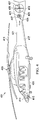
- FIG. 1 illustrates a rotorcraft 101 equipped with a bidirectional rotor blade 103 according to this disclosure.
- Rotorcraft 101 comprises a main rotor system 105 carried by a fuselage 107 and a tail rotor system 109 carried by the fuselage 107.
- One or more main-rotor blades 111 operably associated with main rotor system 105 provide lift for rotorcraft 101 and are controlled with a plurality of control sticks within the fuselage 107.
- a pilot can manipulate cyclic stick 113 to cyclically change the pitch angle of main rotor blades 111, thus providing lateral and longitudinal flight direction, and/or manipulate pedals 115 for controlling yaw direction with varied RPM and rotational direction of the tail rotor system.
- the pilot can adjust the collective stick 117 to collectively change the pitch angles of all the main-rotor blades 111.
- Tail rotor system 109 utilizes a bidirectional aircraft rotor blade 103 having a fixed pitch and configured for producing a yaw moment of a selected magnitude and a selective direction. Because the bidirectional aircraft rotor blade 103 is fixed in pitch, the RPM and the direction of rotation are varied by manipulation of the pedals 115 to vary the magnitude and direction of the yaw moment.
- Rotorcraft 101 features a torque source, such as an engine or electric motor, driving the main rotor system 105 along with the tail rotor system 109.
- Tail rotor system 109 can be rotationally coupled to a transmission comprising a clutch that enables the tail rotor system 109 to both vary the RPM and the rotational direction of the tail rotor system 109.
- the tail rotor system 109 is driven by a dedicated bidirectional electric motor. In either case, the bidirectional aircraft rotor blade 103 is affixed to a hub 121.
- the bidirectional aircraft rotor blade 103 is comprised of a leading edge that is identical to a trailing edge, both having identical rounded edge profiles. Furthermore, the bidirectional aircraft rotor blade 103 is comprised of an upper surface having a greater upper camber as compared to a lower camber of the lower surface. The combination of the camber and fixed pitch make the bidirectional rotor blade 103 efficient in a forward direction 123, but results in the bidirectional aircraft rotor blade 103 being less efficient in a reverse direction 125.
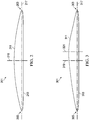
- FIG. 2 illustrates a bidirectional aircraft rotor blade 201 for a rotorcraft.
- Rotor blade 201 is comprised of a leading edge 203, a trailing edge 205, an upper surface 211, and a lower surface 213.
- Chord axis 217 connects the leading edge 203 and the trailing edge 205.
- the median axis 219 is located midway along the chord axis between the leading edge 203 and the trailing edge 205.
- the upper surface 211 connects the leading edge 203 to the trailing edge 205, and the lower surface 213 connects the leading edge 203 to the trailing edge 205.
- a thickness of the rotor blade 201 is at its maximum at the median axis 219. Furthermore, the leading edge 203 and the trailing edge 205 are identical in profile shape, and the rotor blade 201 is mirrored about the median axis. Placing the maximum thickness position at 50% of the chord length makes the rotor blade symmetric about the median axis 219, which provides reverse direction performance. In a preferred embodiment, the lower camber is at or below 2% to help reverse direction performance.
- FIG. 3 illustrates a bidirectional aircraft rotor blade 301 for a rotorcraft.
- Rotor blade 301 is comprised of a leading edge 303, a trailing edge 305, an upper surface 311, and a lower surface 313.
- Chord axis 317 connects the leading edge 303 and the trailing edge 305.
- a median axis 319 is located midway between the leading edge 303 and the trailing edge 305.
- the upper surface 311 connects the leading edge 303 to the trailing edge 305, and the lower surface 313 connects the leading edge 303 to the trailing edge 305.
- a maximum thickness axis 321 is located where a thickness of the rotor blade 301 is at a maximum, and the axis 321 is located a distance away from the median axis 319, resulting in the rotor blade 301 being non-symmetric about the median axis 319.
- the leading edge 303 and the trailing edge 305 are identical in profile shape.
- FIG. 4 illustrates a rotorcraft 401 equipped with two bidirectional rotor systems according to this disclosure.
- Rotorcraft 401 comprises a main rotor system 403 carried by a fuselage 405, a first tail rotor system 407, and a second tail rotor system 409.
- One or more main-rotor blades 411 operably associated with main rotor system 403 provide lift for rotorcraft 401 and are controlled with a flight control computer 413 having a tail rotor controller 415.
- a pilot can manipulate a cyclic stick to cyclically change the pitch angle of main rotor blades 411, thus providing lateral and longitudinal flight direction, and/or manipulate pedals for controlling yaw direction by varying the RPM and reversing the direction of the first and second tail rotor systems 407, 409.
- the pilot can adjust a collective stick to collectively change the pitch angles of all of the main rotor blades 411.
- the flight control computer 413 and the tail rotor controller 415 are wired 417 to the first tail rotor system 407 and wired to the second tail rotor system 409. Both the first tail rotor system 407 the second tail rotor system 409 are in the tail rotor assembly 419.
- the tail rotor assembly 419 of rotorcraft 401 is attached to the fuselage 405 of the rotorcraft 401 by tail boom 421.
- the first tail rotor system 407 is comprised of a first tail rotor blade 423 and a second tail rotor blade 425.
- the second tail rotor system 409 is comprised of a third tail rotor blade 427 and a fourth tail rotor blade 429.
- the flight control computer 413 can selectively adjust the RPM of each tail rotor system and the direction of rotation of each tail rotor system to produce a yaw moment of a selected magnitude and direction for varying the yaw attitude of the rotorcraft 401.
- the first tail rotor system 407 is driven by a first electric motor.
- a pitch of the first tail rotor blade 423 and the second tail rotor blade 425 is fixed.
- the RPM and/or a direction of rotation of the first electric motor is varied to vary a yaw moment of the first tail rotor system 407.
- the second tail rotor system 409 is driven by a second electric motor.
- a pitch of the third tail rotor blade 427 and the fourth tail rotor blade 429 is fixed.
- the RPM and/or a direction of rotation of the first electric motor is varied to vary a yaw moment of the first tail rotor system 409.
- first tail rotor system 407 has a smaller diameter than the second tail rotor system 409.
- each tail rotor system is equal in diameter or first tail rotor system 407 has a larger diameter than the second tail rotor system 409.
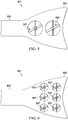
- FIG. 5 illustrates a rotorcraft's tail boom equipped with two tail rotors having bidirectional aircraft rotor blades according to this disclosure.
- Combined tail rotor system 501 is in a vertical stabilizer 503 attached to tail boom 505.
- Combined tail rotor system 501 is comprised of a first tail rotor system 507 and second tail rotor system 509 of equal diameter.
- Each tail rotor system in the combined tail rotor system 501 is fixed in pitch and features bidirectional aircraft rotor blades like those of the bidirectional aircraft rotor 301.
- Second tail rotor system 509 is comprised of a single blade that spans an entire length of the tail rotor system.
- the first tail rotor system 507 is controlled concurrently with the second tail rotor system 509.
- the first tail rotor system 507 is controlled independently of the second tail rotor system 509.
- FIG. 6 illustrates a rotorcraft's tail boom equipped with an array of tail rotors having bidirectional aircraft rotor blades according to this disclosure.
- Combined tail rotor system 601 is in a vertical stabilizer 603 attached to tail boom 605.
- Combined tail rotor system 601 is comprised of a plurality of tail rotor systems 607 having equal diameters.
- Each tail rotor system in the combined tail rotor system 601 is fixed in pitch and features bidirectional aircraft rotor blades like those of the bidirectional aircraft rotor 301.
- FIG. 7 illustrates a rotorcraft's tail boom equipped with several tail rotors having bidirectional aircraft rotor blades according to this disclosure.
- Combined tail rotor system 701 is in a vertical stabilizer 703 attached to tail boom 705.
- Combined tail rotor system 701 is comprised of a plurality of larger tail rotor systems 707 and smaller tail rotor systems 709.
- Each tail rotor system 707, 709 in the combined tail rotor system 701 is fixed in pitch and features bidirectional aircraft rotor blades such as the bidirectional aircraft rotor 301. It should be apparent that tail rotor systems 707, 709 while shown as providing yaw control could be mounted horizontally to provide lift to rotorcraft.
- the bidirectional aircraft rotor provides thrust while moving in both forward and reverse directions.
- the bidirectional aircraft rotor provides rotorcraft with quicker and more efficient control of yaw during flight, thereby enabling the rotorcraft to be more responsive to the pilot and the flight control system.
- R Ri +k ⁇ (R u -R 1 ), wherein k is a variable ranging from 1 percent to 100 percent with a 1 percent increment, i.e., k is 1 percent, 2 percent, 3 percent, 4 percent, 5 percent,... 50 percent, 51 percent, 52 percent,..., 95 percent, 96 percent, 95 percent, 98 percent, 99 percent, or 100 percent.
- any numerical range defined by two R numbers as defined in the above is also specifically disclosed.
Landscapes
- Engineering & Computer Science (AREA)
- Aviation & Aerospace Engineering (AREA)
- Mechanical Engineering (AREA)
- Physics & Mathematics (AREA)
- Fluid Mechanics (AREA)
- Turbine Rotor Nozzle Sealing (AREA)
- Toys (AREA)
- Radar, Positioning & Navigation (AREA)
- Remote Sensing (AREA)
- General Physics & Mathematics (AREA)
- Automation & Control Theory (AREA)
- Nozzles For Electric Vacuum Cleaners (AREA)
Abstract
Description
- Not applicable.
- Not applicable.
- Conventional rotorcraft feature rotor systems that spin in a single direction. Rotor systems that rotate a single direction utilize rotor blades, or airfoils, specifically configured for a chordwise airstream passing over the rotor blades in a single direction. Conventional rotor blades typically feature a maximum thickness offset closer to a leading edge than the trailing edge, such as between a leading edge of the blade and about one-third of a chord length of the blade nearest the leading edge. The offset maximum thickness and/or camber of conventional airfoils is optimized to generate lift as the airfoil is rotated in a single "normal" direction. Conventional rotors typically operate at a relatively constant RPM and are pitch controlled, wherein their blades are rotated about a spanwise pitch axis to vary the amount of lift generated by the blades.
-
-
Figure 1 is a side view of a rotorcraft according to this disclosure. -
Figure 2 is an end view of a bidirectional rotor blade according to this disclosure. -
Figure 3 is an end view of another bidirectional rotor blade according to this disclosure. -
Figure 4 is a side view of another rotorcraft according to this disclosure. -
Figure 5 is a partial side view of a tail boom comprising rotors according to this disclosure. -
Figure 6 is a partial side view of another tail boom comprising rotors according to this disclosure. -
Figure 7 is a partial side view of another tail boom comprising rotors according to this disclosure. - In this disclosure, reference may be made to the spatial relationships between various components and to the spatial orientation of various aspects of components as the devices are depicted in the attached drawings. However, as will be recognized by those skilled in the art after a complete reading of this disclosure, the devices, members, apparatuses, etc. described herein may be positioned in any desired orientation. Thus, the use of terms such as "above," "below," "upper," "lower," or other like terms to describe a spatial relationship between various components or to describe the spatial orientation of aspects of such components should be understood to describe a relative relationship between the components or a spatial orientation of aspects of such components, respectively, as the device described herein may be oriented in any desired direction.
- This disclosure describes a rotorcraft having rotors that can change a direction of their rotation and are utilized on rotor systems that vary RPM of the rotor. Changing the direction of a rotor's rotation requires rotor blades that are configured for relatively efficient operation in both directions. The bidirectional rotor blades feature a leading edge along with a trailing edge that are mirrors of each other along a median of the rotor blade. A profile of the leading edge of the rotor blade is identical to a profile of the trailing edge of the rotor blade.
- A bidirectional rotor system will have to provide thrust when operated in both the forward direction, with a leading edge leading, and the negative direction, with the trailing edge leading, and an airfoil with a relatively sharp leading edge and a rounded trailing edge will provide lesser flow separation in both rotational directions. Bidirectional rotor systems also present a challenge in requiring the rotor to stop and change directions, but RPM-controlled rotors are typically designed to have reduced chord length and inertia.
-
Figure 1 illustrates arotorcraft 101 equipped with abidirectional rotor blade 103 according to this disclosure. Rotorcraft 101 comprises amain rotor system 105 carried by afuselage 107 and atail rotor system 109 carried by thefuselage 107. One or more main-rotor blades 111 operably associated withmain rotor system 105 provide lift forrotorcraft 101 and are controlled with a plurality of control sticks within thefuselage 107. For example, during flight a pilot can manipulatecyclic stick 113 to cyclically change the pitch angle ofmain rotor blades 111, thus providing lateral and longitudinal flight direction, and/or manipulatepedals 115 for controlling yaw direction with varied RPM and rotational direction of the tail rotor system. Furthermore, the pilot can adjust the collective stick 117 to collectively change the pitch angles of all the main-rotor blades 111. -
Tail rotor system 109 utilizes a bidirectionalaircraft rotor blade 103 having a fixed pitch and configured for producing a yaw moment of a selected magnitude and a selective direction. Because the bidirectionalaircraft rotor blade 103 is fixed in pitch, the RPM and the direction of rotation are varied by manipulation of thepedals 115 to vary the magnitude and direction of the yaw moment. Rotorcraft 101 features a torque source, such as an engine or electric motor, driving themain rotor system 105 along with thetail rotor system 109.Tail rotor system 109 can be rotationally coupled to a transmission comprising a clutch that enables thetail rotor system 109 to both vary the RPM and the rotational direction of thetail rotor system 109. Alternatively, thetail rotor system 109 is driven by a dedicated bidirectional electric motor. In either case, the bidirectionalaircraft rotor blade 103 is affixed to ahub 121. - The bidirectional
aircraft rotor blade 103 is comprised of a leading edge that is identical to a trailing edge, both having identical rounded edge profiles. Furthermore, the bidirectionalaircraft rotor blade 103 is comprised of an upper surface having a greater upper camber as compared to a lower camber of the lower surface. The combination of the camber and fixed pitch make thebidirectional rotor blade 103 efficient in a forward direction 123, but results in the bidirectionalaircraft rotor blade 103 being less efficient in areverse direction 125. -
Figure 2 illustrates a bidirectionalaircraft rotor blade 201 for a rotorcraft.Rotor blade 201 is comprised of a leadingedge 203, atrailing edge 205, anupper surface 211, and alower surface 213.Chord axis 217 connects the leadingedge 203 and thetrailing edge 205. Themedian axis 219 is located midway along the chord axis between the leadingedge 203 and thetrailing edge 205. Theupper surface 211 connects the leadingedge 203 to thetrailing edge 205, and thelower surface 213 connects the leadingedge 203 to thetrailing edge 205. - A thickness of the
rotor blade 201 is at its maximum at themedian axis 219. Furthermore, the leadingedge 203 and thetrailing edge 205 are identical in profile shape, and therotor blade 201 is mirrored about the median axis. Placing the maximum thickness position at 50% of the chord length makes the rotor blade symmetric about themedian axis 219, which provides reverse direction performance. In a preferred embodiment, the lower camber is at or below 2% to help reverse direction performance. -
Figure 3 illustrates a bidirectionalaircraft rotor blade 301 for a rotorcraft.Rotor blade 301 is comprised of a leadingedge 303, atrailing edge 305, anupper surface 311, and alower surface 313. Chord axis 317 connects the leadingedge 303 and thetrailing edge 305. Amedian axis 319 is located midway between the leadingedge 303 and thetrailing edge 305. Theupper surface 311 connects the leadingedge 303 to thetrailing edge 305, and thelower surface 313 connects the leadingedge 303 to thetrailing edge 305. - A
maximum thickness axis 321 is located where a thickness of therotor blade 301 is at a maximum, and theaxis 321 is located a distance away from themedian axis 319, resulting in therotor blade 301 being non-symmetric about themedian axis 319. The leadingedge 303 and thetrailing edge 305 are identical in profile shape. -
Figure 4 illustrates arotorcraft 401 equipped with two bidirectional rotor systems according to this disclosure. Rotorcraft 401 comprises amain rotor system 403 carried by afuselage 405, a firsttail rotor system 407, and a secondtail rotor system 409. One or more main-rotor blades 411 operably associated withmain rotor system 403 provide lift forrotorcraft 401 and are controlled with aflight control computer 413 having atail rotor controller 415. For example, during flight a pilot can manipulate a cyclic stick to cyclically change the pitch angle ofmain rotor blades 411, thus providing lateral and longitudinal flight direction, and/or manipulate pedals for controlling yaw direction by varying the RPM and reversing the direction of the first and secondtail rotor systems main rotor blades 411. - The
flight control computer 413 and thetail rotor controller 415 are wired 417 to the firsttail rotor system 407 and wired to the secondtail rotor system 409. Both the firsttail rotor system 407 the secondtail rotor system 409 are in thetail rotor assembly 419. Thetail rotor assembly 419 ofrotorcraft 401 is attached to thefuselage 405 of therotorcraft 401 bytail boom 421. The firsttail rotor system 407 is comprised of a firsttail rotor blade 423 and a secondtail rotor blade 425. The secondtail rotor system 409 is comprised of a thirdtail rotor blade 427 and a fourthtail rotor blade 429. Theflight control computer 413 can selectively adjust the RPM of each tail rotor system and the direction of rotation of each tail rotor system to produce a yaw moment of a selected magnitude and direction for varying the yaw attitude of therotorcraft 401. - The first
tail rotor system 407 is driven by a first electric motor. A pitch of the firsttail rotor blade 423 and the secondtail rotor blade 425 is fixed. The RPM and/or a direction of rotation of the first electric motor is varied to vary a yaw moment of the firsttail rotor system 407. - The second
tail rotor system 409 is driven by a second electric motor. A pitch of the thirdtail rotor blade 427 and the fourthtail rotor blade 429 is fixed. The RPM and/or a direction of rotation of the first electric motor is varied to vary a yaw moment of the firsttail rotor system 409. - Combining the yaw moment of the first
tail rotor system 407 with the yaw moment of the secondtail rotor system 409 allows the pilot to quickly and efficiently yaw the aircraft. In the preferred embodiment the firsttail rotor system 407 has a smaller diameter than the secondtail rotor system 409. In alternative embodiments, each tail rotor system is equal in diameter or firsttail rotor system 407 has a larger diameter than the secondtail rotor system 409. -
Figure 5 illustrates a rotorcraft's tail boom equipped with two tail rotors having bidirectional aircraft rotor blades according to this disclosure. Combinedtail rotor system 501 is in avertical stabilizer 503 attached totail boom 505. Combinedtail rotor system 501 is comprised of a firsttail rotor system 507 and secondtail rotor system 509 of equal diameter. Each tail rotor system in the combinedtail rotor system 501 is fixed in pitch and features bidirectional aircraft rotor blades like those of thebidirectional aircraft rotor 301. Secondtail rotor system 509 is comprised of a single blade that spans an entire length of the tail rotor system. In the preferred embodiment, the firsttail rotor system 507 is controlled concurrently with the secondtail rotor system 509. Alternatively, the firsttail rotor system 507 is controlled independently of the secondtail rotor system 509. -
Figure 6 illustrates a rotorcraft's tail boom equipped with an array of tail rotors having bidirectional aircraft rotor blades according to this disclosure. Combinedtail rotor system 601 is in avertical stabilizer 603 attached totail boom 605. Combinedtail rotor system 601 is comprised of a plurality oftail rotor systems 607 having equal diameters. Each tail rotor system in the combinedtail rotor system 601 is fixed in pitch and features bidirectional aircraft rotor blades like those of thebidirectional aircraft rotor 301. -
Figure 7 illustrates a rotorcraft's tail boom equipped with several tail rotors having bidirectional aircraft rotor blades according to this disclosure. Combinedtail rotor system 701 is in avertical stabilizer 703 attached totail boom 705. Combinedtail rotor system 701 is comprised of a plurality of largertail rotor systems 707 and smallertail rotor systems 709. Eachtail rotor system tail rotor system 701 is fixed in pitch and features bidirectional aircraft rotor blades such as thebidirectional aircraft rotor 301. It should be apparent thattail rotor systems - It should be noted that the bidirectional aircraft rotor provides thrust while moving in both forward and reverse directions. The bidirectional aircraft rotor provides rotorcraft with quicker and more efficient control of yaw during flight, thereby enabling the rotorcraft to be more responsive to the pilot and the flight control system.
- At least one embodiment is disclosed, and variations, combinations, and/or modifications of the embodiment(s) and/or features of the embodiment(s) made by a person having ordinary skill in the art are within the scope of this disclosure. Alternative embodiments that result from combining, integrating, and/or omitting features of the embodiment(s) are also within the scope of this disclosure. Where numerical ranges or limitations are expressly stated, such express ranges or limitations should be understood to include iterative ranges or limitations of like magnitude falling within the expressly stated ranges or limitations (e.g., from about 1 to about 10 includes, 2, 3, 4, etc.; greater than 0.10 includes 0.11, 0.12, 0.13, etc.). For example, whenever a numerical range with a lower limit, R1, and an upper limit, Ru, is disclosed, any number falling within the range is specifically disclosed. In particular, the following numbers within the range are specifically disclosed: R=Ri +k ∗ (Ru-R1), wherein k is a variable ranging from 1 percent to 100 percent with a 1 percent increment, i.e., k is 1 percent, 2 percent, 3 percent, 4 percent, 5 percent,... 50 percent, 51 percent, 52 percent,..., 95 percent, 96 percent, 95 percent, 98 percent, 99 percent, or 100 percent. Moreover, any numerical range defined by two R numbers as defined in the above is also specifically disclosed. Use of the term "optionally" with respect to any element of a claim means that the element is required, or alternatively, the element is not required, both alternatives being within the scope of the claim. Use of broader terms such as comprises, includes, and having should be understood to provide support for narrower terms such as consisting of, consisting essentially of, and comprised substantially of. Accordingly, the scope of protection is not limited by the description set out above but is defined by the claims that follow, that scope including all equivalents of the subject matter of the claims. Each and every claim is incorporated as further disclosure into the specification and the claims are embodiments) of the present invention. Also, the phrases "at least one of A, B, and C" and "A and/or B and/or C" should each be interpreted to include only A, only B, only C, or any combination of A, B, and C.
- The following clauses (not claims) are statements defining aspects of the invention.
- 1. A tail rotor for a rotorcraft, comprising:
- a hub driven by a torque source; and
- a first tail rotor blade affixed to the hub;
- wherein a pitch of the first tail rotor blade is fixed; and
- wherein a profile of a leading edge of the first tail rotor blade is identical to a profile of a trailing edge of the first tail rotor blade.
- 2. The tail rotor of clause 1, further comprising:
a second tail rotor blade affixed to the hub. - 3. The tail rotor of clause 1, wherein a maximum thickness of the first tail rotor blade is midway between the leading edge and the trailing edge.
- 4. The tail rotor of clause 3, wherein an upper camber is greater than a lower camber.
- 5. The tail rotor of clause 4, wherein the lower camber is less than or equal to 2 percent.
- 6. The tail rotor of clause 4, wherein a maximum of the upper camber is located where the maximum thickness is located.
- 7. The tail rotor of clause 1, wherein the torque source is an electric motor.
- 8. The tail rotor of clause 1, wherein the torque source is an engine.
- 9. A rotorcraft having a main rotor system, comprising:
- a first tail rotor system having;
- bidirectional rotor blades with a fixed pitch; and
- a first torque source configured to rotate the first tail rotor system;
- wherein an RPM of the first torque source is variable; and
- wherein a direction of rotation of the first tail rotor system is reversible in flight.
- a first tail rotor system having;
- 10. The rotorcraft of clause 9, wherein the torque source is an electric motor.
- 11. The rotorcraft of clause 9, further comprising:
- a second tail rotor system having;
- bidirectional rotor blades with a fixed pitch; and
- a second torque source configured to rotate the second tail rotor system;
- wherein an RPM of the second torque source is variable; and
- wherein a direction of rotation of the second tail rotor system is reversible in flight.
- a second tail rotor system having;
- 12. The rotorcraft of clause 11, wherein a diameter of the first tail rotor system is unequal to a diameter of the second tail rotor system.
- 13. The rotorcraft of clause 11, wherein a diameter of the first tail rotor system is equal to a diameter of the second tail rotor system.
- 14. The rotorcraft of clause 9, further comprising:
- a third tail rotor system having;
- bidirectional rotor blades with a fixed pitch; and
- a third torque source configured to rotate the third tail rotor system;
- wherein the third tail rotor system is fixed in pitch;
- wherein an RPM of the third tail rotor system is variable; and
- wherein a direction of rotation of the third tail rotor system is reversible in flight.
- a third tail rotor system having;
- 15. A method of controlling a yaw moment of a tail rotor system of a rotorcraft, comprising:
- providing a first tail rotor system having;
- a first hub; and
- a first tail rotor blade affixed to the first hub with a fixed pitch;
- wherein a profile of a leading edge of the first tail rotor blade is identical to a profile of a trailing edge of the first tail rotor blade; and
- varying an RPM of the first tail rotor system.
- providing a first tail rotor system having;
- 16. The method of clause 15, further comprising reversing a direction of rotation of the first tail rotor system.
- 17. The method of clause 15, further comprising:
- providing a second tail rotor system having;
- a second hub; and
- a second tail rotor blade affixed to the second hub with a fixed pitch;
- wherein a profile of a leading edge of the second tail rotor blade is identical to a profile of a trailing edge of the second tail rotor blade; and
- varying an RPM of the second tail rotor system.
- providing a second tail rotor system having;
- 18. The method of clause 17, further comprising reversing a direction of rotation of the second tail rotor system.
- 19. The method of clause 17, wherein the first tail rotor system is controlled concurrently with the second tail rotor system.
- 20. The method of clause 17, wherein the first tail rotor system is controlled independently of the second tail rotor system.
Claims (7)
- A tail rotor for a rotorcraft, comprising:a hub driven by a torque source; anda first tail rotor blade affixed to the hub;wherein a pitch of the first tail rotor blade is fixed; andwherein a profile of a leading edge of the first tail rotor blade is identical to a profile of a trailing edge of the first tail rotor blade.
- The tail rotor of claim 1, further comprising:
a second tail rotor blade affixed to the hub. - The tail rotor of claim 1 or of claim 2, wherein a maximum thickness of the first tail rotor blade is midway between the leading edge and the trailing edge.
- The tail rotor of claim 3, wherein an upper camber is greater than a lower camber.
- The tail rotor of claim 4, wherein: -(i) the lower camber is less than or equal to 2 percent; and/or(ii) a maximum of the upper camber is located where the maximum thickness is located.
- The tail rotor of claim 1 or of any of claims 2 to 5, wherein the torque source is an electric motor; or wherein the torque source is an engine.
- The tail rotor of any preceding claim, wherein the first tail rotor blade is a bidirectional tail rotor blade that is symmetric about a median axis of the bidirectional tail rotor blade, wherein the median axis is located midway along a chord axis between a leading edge of the bidirectional tail rotor blade and a trailing edge of the bidirectional tail rotor blade, and wherein a maximum thickness of the bidirectional tail rotor blade is midway between the leading edge and the trailing edge.
Applications Claiming Priority (2)
| Application Number | Priority Date | Filing Date | Title |
|---|---|---|---|
| US16/178,349 US20200140077A1 (en) | 2018-11-01 | 2018-11-01 | Bidirectional aircraft rotor |
| EP18212490.9A EP3647191B1 (en) | 2018-11-01 | 2018-12-13 | Bidirectional aircraft rotor |
Related Parent Applications (1)
| Application Number | Title | Priority Date | Filing Date |
|---|---|---|---|
| EP18212490.9A Division EP3647191B1 (en) | 2018-11-01 | 2018-12-13 | Bidirectional aircraft rotor |
Publications (2)
| Publication Number | Publication Date |
|---|---|
| EP3878739A1 true EP3878739A1 (en) | 2021-09-15 |
| EP3878739B1 EP3878739B1 (en) | 2023-04-12 |
Family
ID=64665504
Family Applications (2)
| Application Number | Title | Priority Date | Filing Date |
|---|---|---|---|
| EP21167220.9A Active EP3878739B1 (en) | 2018-11-01 | 2018-12-13 | Bidirectional aircraft rotor |
| EP18212490.9A Active EP3647191B1 (en) | 2018-11-01 | 2018-12-13 | Bidirectional aircraft rotor |
Family Applications After (1)
| Application Number | Title | Priority Date | Filing Date |
|---|---|---|---|
| EP18212490.9A Active EP3647191B1 (en) | 2018-11-01 | 2018-12-13 | Bidirectional aircraft rotor |
Country Status (2)
| Country | Link |
|---|---|
| US (1) | US20200140077A1 (en) |
| EP (2) | EP3878739B1 (en) |
Families Citing this family (3)
| Publication number | Priority date | Publication date | Assignee | Title |
|---|---|---|---|---|
| FR3110893B1 (en) * | 2020-05-29 | 2022-07-01 | Airbus Helicopters | Method of construction of a rotor blade for a rotorcraft, blades and rotorcraft |
| US11772785B2 (en) * | 2020-12-01 | 2023-10-03 | Textron Innovations Inc. | Tail rotor configurations for rotorcraft yaw control systems |
| US11745886B2 (en) * | 2021-06-29 | 2023-09-05 | Beta Air, Llc | Electric aircraft for generating a yaw force |
Citations (9)
| Publication number | Priority date | Publication date | Assignee | Title |
|---|---|---|---|---|
| FR411538A (en) * | 1910-01-13 | 1910-06-18 | Alexandre Fougeron | Propeller for air navigation |
| GB296717A (en) * | 1927-06-02 | 1928-09-03 | Stone J & Co Ltd | Improvements in screw propellers |
| US2027647A (en) * | 1931-10-17 | 1936-01-14 | Jeffrey Mfg Co | Ventilator |
| US2408788A (en) * | 1939-06-16 | 1946-10-08 | Ludington Charles Townsend | Airfoil |
| US2609055A (en) * | 1949-11-08 | 1952-09-02 | Hartzell Propeller Fan Company | Reversible propeller blade |
| US4966526A (en) * | 1989-07-13 | 1990-10-30 | United Technologies Corporation | Mechanically actuated slot for circulation control rotor |
| WO1993024360A1 (en) * | 1992-05-29 | 1993-12-09 | Gori Af 1902 As | A propeller having optimum efficiency in forward and rearward navigation |
| US20070231148A1 (en) * | 2006-04-03 | 2007-10-04 | Lehoczky Kalman N | Reversing free flow propeller turbine |
| EP3254962A1 (en) * | 2016-06-03 | 2017-12-13 | Bell Helicopter Textron Inc. | Electric distributed propulsion anti-torque redundant power and control system |
-
2018
- 2018-11-01 US US16/178,349 patent/US20200140077A1/en not_active Abandoned
- 2018-12-13 EP EP21167220.9A patent/EP3878739B1/en active Active
- 2018-12-13 EP EP18212490.9A patent/EP3647191B1/en active Active
Patent Citations (10)
| Publication number | Priority date | Publication date | Assignee | Title |
|---|---|---|---|---|
| FR411538A (en) * | 1910-01-13 | 1910-06-18 | Alexandre Fougeron | Propeller for air navigation |
| GB296717A (en) * | 1927-06-02 | 1928-09-03 | Stone J & Co Ltd | Improvements in screw propellers |
| US2027647A (en) * | 1931-10-17 | 1936-01-14 | Jeffrey Mfg Co | Ventilator |
| US2408788A (en) * | 1939-06-16 | 1946-10-08 | Ludington Charles Townsend | Airfoil |
| US2609055A (en) * | 1949-11-08 | 1952-09-02 | Hartzell Propeller Fan Company | Reversible propeller blade |
| US4966526A (en) * | 1989-07-13 | 1990-10-30 | United Technologies Corporation | Mechanically actuated slot for circulation control rotor |
| WO1993024360A1 (en) * | 1992-05-29 | 1993-12-09 | Gori Af 1902 As | A propeller having optimum efficiency in forward and rearward navigation |
| EP0642437B1 (en) * | 1992-05-29 | 1997-03-26 | Gori Marine As | A propeller having optimum efficiency in forward and rearward navigation |
| US20070231148A1 (en) * | 2006-04-03 | 2007-10-04 | Lehoczky Kalman N | Reversing free flow propeller turbine |
| EP3254962A1 (en) * | 2016-06-03 | 2017-12-13 | Bell Helicopter Textron Inc. | Electric distributed propulsion anti-torque redundant power and control system |
Also Published As
| Publication number | Publication date |
|---|---|
| EP3647191B1 (en) | 2021-04-14 |
| EP3878739B1 (en) | 2023-04-12 |
| US20200140077A1 (en) | 2020-05-07 |
| EP3647191A1 (en) | 2020-05-06 |
Similar Documents
| Publication | Publication Date | Title |
|---|---|---|
| US11713113B2 (en) | Compound rotorcraft with propeller | |
| EP3483065B1 (en) | Multirotor aircraft with collective for autorotation | |
| EP3000722B1 (en) | Aircraft | |
| EP2511177B1 (en) | Helicopter with cycloidal rotor system | |
| JP5676824B2 (en) | Private aircraft | |
| US20130134264A1 (en) | Electric Motor Powered Rotor Drive for Slowed Rotor Winged Aircraft | |
| US8113460B2 (en) | Fast hybrid helicopter with long range and an optimized lift rotor | |
| US20130134253A1 (en) | Power Rotor Drive for Slowed Rotor Winged Aircraft | |
| US20210107665A1 (en) | Redundant drive train for pylon mounted rotors | |
| IL273314B2 (en) | A wing tilt actuation system for electric vertical take-off and landing (VTOL) aircraft | |
| WO2018064209A1 (en) | Tilt-wing aircraft | |
| CN107458597A (en) | Method for the reaction torque component and system and operation helicopter of helicopter | |
| US10407163B2 (en) | Aircraft control system and method | |
| CN104470800A (en) | Wing adjusting mechanism | |
| EP3728028B1 (en) | Wing and rotor vectoring system for aircraft | |
| CN109018342B (en) | Trochoidal fan wing device, tilting cycloidal fan wing aircraft and control method | |
| EP3647191A1 (en) | Bidirectional aircraft rotor | |
| US20240278909A1 (en) | Rotor position control system | |
| CN104973241A (en) | Unmanned aerial vehicle with main and auxiliary multi-rotor structure | |
| US20100258671A1 (en) | Aircraft having helicopter rotor and front mounted propeller | |
| WO2013155402A1 (en) | Electric motor powered rotor drive for slowed rotor winged aircraft | |
| CN111348183A (en) | aircraft | |
| EP3931086B1 (en) | A coaxial rotorcraft system and a method for controlling the same | |
| US20020005455A1 (en) | Rotor control with negative collective in high speed auto-rotation | |
| RU2569233C1 (en) | Control over helicopter rotor jet drive and device to this end |
Legal Events
| Date | Code | Title | Description |
|---|---|---|---|
| PUAI | Public reference made under article 153(3) epc to a published international application that has entered the european phase |
Free format text: ORIGINAL CODE: 0009012 |
|
| STAA | Information on the status of an ep patent application or granted ep patent |
Free format text: STATUS: EXAMINATION IS IN PROGRESS |
|
| 17P | Request for examination filed |
Effective date: 20210407 |
|
| AC | Divisional application: reference to earlier application |
Ref document number: 3647191 Country of ref document: EP Kind code of ref document: P |
|
| AK | Designated contracting states |
Kind code of ref document: A1 Designated state(s): AL AT BE BG CH CY CZ DE DK EE ES FI FR GB GR HR HU IE IS IT LI LT LU LV MC MK MT NL NO PL PT RO RS SE SI SK SM TR |
|
| GRAP | Despatch of communication of intention to grant a patent |
Free format text: ORIGINAL CODE: EPIDOSNIGR1 |
|
| STAA | Information on the status of an ep patent application or granted ep patent |
Free format text: STATUS: GRANT OF PATENT IS INTENDED |
|
| INTG | Intention to grant announced |
Effective date: 20221107 |
|
| GRAS | Grant fee paid |
Free format text: ORIGINAL CODE: EPIDOSNIGR3 |
|
| GRAA | (expected) grant |
Free format text: ORIGINAL CODE: 0009210 |
|
| STAA | Information on the status of an ep patent application or granted ep patent |
Free format text: STATUS: THE PATENT HAS BEEN GRANTED |
|
| RAP1 | Party data changed (applicant data changed or rights of an application transferred) |
Owner name: TEXTRON INNOVATIONS INC. |
|
| AC | Divisional application: reference to earlier application |
Ref document number: 3647191 Country of ref document: EP Kind code of ref document: P |
|
| AK | Designated contracting states |
Kind code of ref document: B1 Designated state(s): AL AT BE BG CH CY CZ DE DK EE ES FI FR GB GR HR HU IE IS IT LI LT LU LV MC MK MT NL NO PL PT RO RS SE SI SK SM TR |
|
| REG | Reference to a national code |
Ref country code: GB Ref legal event code: FG4D |
|
| REG | Reference to a national code |
Ref country code: CH Ref legal event code: EP |
|
| REG | Reference to a national code |
Ref country code: DE Ref legal event code: R096 Ref document number: 602018048470 Country of ref document: DE |
|
| REG | Reference to a national code |
Ref country code: IE Ref legal event code: FG4D |
|
| REG | Reference to a national code |
Ref country code: AT Ref legal event code: REF Ref document number: 1559644 Country of ref document: AT Kind code of ref document: T Effective date: 20230515 |
|
| P01 | Opt-out of the competence of the unified patent court (upc) registered |
Effective date: 20230602 |
|
| REG | Reference to a national code |
Ref country code: LT Ref legal event code: MG9D |
|
| REG | Reference to a national code |
Ref country code: NL Ref legal event code: MP Effective date: 20230412 |
|
| REG | Reference to a national code |
Ref country code: AT Ref legal event code: MK05 Ref document number: 1559644 Country of ref document: AT Kind code of ref document: T Effective date: 20230412 |
|
| PG25 | Lapsed in a contracting state [announced via postgrant information from national office to epo] |
Ref country code: NL Free format text: LAPSE BECAUSE OF FAILURE TO SUBMIT A TRANSLATION OF THE DESCRIPTION OR TO PAY THE FEE WITHIN THE PRESCRIBED TIME-LIMIT Effective date: 20230412 |
|
| PG25 | Lapsed in a contracting state [announced via postgrant information from national office to epo] |
Ref country code: SE Free format text: LAPSE BECAUSE OF FAILURE TO SUBMIT A TRANSLATION OF THE DESCRIPTION OR TO PAY THE FEE WITHIN THE PRESCRIBED TIME-LIMIT Effective date: 20230412 Ref country code: PT Free format text: LAPSE BECAUSE OF FAILURE TO SUBMIT A TRANSLATION OF THE DESCRIPTION OR TO PAY THE FEE WITHIN THE PRESCRIBED TIME-LIMIT Effective date: 20230814 Ref country code: NO Free format text: LAPSE BECAUSE OF FAILURE TO SUBMIT A TRANSLATION OF THE DESCRIPTION OR TO PAY THE FEE WITHIN THE PRESCRIBED TIME-LIMIT Effective date: 20230712 Ref country code: ES Free format text: LAPSE BECAUSE OF FAILURE TO SUBMIT A TRANSLATION OF THE DESCRIPTION OR TO PAY THE FEE WITHIN THE PRESCRIBED TIME-LIMIT Effective date: 20230412 Ref country code: AT Free format text: LAPSE BECAUSE OF FAILURE TO SUBMIT A TRANSLATION OF THE DESCRIPTION OR TO PAY THE FEE WITHIN THE PRESCRIBED TIME-LIMIT Effective date: 20230412 |
|
| PG25 | Lapsed in a contracting state [announced via postgrant information from national office to epo] |
Ref country code: RS Free format text: LAPSE BECAUSE OF FAILURE TO SUBMIT A TRANSLATION OF THE DESCRIPTION OR TO PAY THE FEE WITHIN THE PRESCRIBED TIME-LIMIT Effective date: 20230412 Ref country code: PL Free format text: LAPSE BECAUSE OF FAILURE TO SUBMIT A TRANSLATION OF THE DESCRIPTION OR TO PAY THE FEE WITHIN THE PRESCRIBED TIME-LIMIT Effective date: 20230412 Ref country code: LV Free format text: LAPSE BECAUSE OF FAILURE TO SUBMIT A TRANSLATION OF THE DESCRIPTION OR TO PAY THE FEE WITHIN THE PRESCRIBED TIME-LIMIT Effective date: 20230412 Ref country code: LT Free format text: LAPSE BECAUSE OF FAILURE TO SUBMIT A TRANSLATION OF THE DESCRIPTION OR TO PAY THE FEE WITHIN THE PRESCRIBED TIME-LIMIT Effective date: 20230412 Ref country code: IS Free format text: LAPSE BECAUSE OF FAILURE TO SUBMIT A TRANSLATION OF THE DESCRIPTION OR TO PAY THE FEE WITHIN THE PRESCRIBED TIME-LIMIT Effective date: 20230812 Ref country code: HR Free format text: LAPSE BECAUSE OF FAILURE TO SUBMIT A TRANSLATION OF THE DESCRIPTION OR TO PAY THE FEE WITHIN THE PRESCRIBED TIME-LIMIT Effective date: 20230412 Ref country code: GR Free format text: LAPSE BECAUSE OF FAILURE TO SUBMIT A TRANSLATION OF THE DESCRIPTION OR TO PAY THE FEE WITHIN THE PRESCRIBED TIME-LIMIT Effective date: 20230713 Ref country code: AL Free format text: LAPSE BECAUSE OF FAILURE TO SUBMIT A TRANSLATION OF THE DESCRIPTION OR TO PAY THE FEE WITHIN THE PRESCRIBED TIME-LIMIT Effective date: 20230412 |
|
| PG25 | Lapsed in a contracting state [announced via postgrant information from national office to epo] |
Ref country code: FI Free format text: LAPSE BECAUSE OF FAILURE TO SUBMIT A TRANSLATION OF THE DESCRIPTION OR TO PAY THE FEE WITHIN THE PRESCRIBED TIME-LIMIT Effective date: 20230412 |
|
| REG | Reference to a national code |
Ref country code: DE Ref legal event code: R097 Ref document number: 602018048470 Country of ref document: DE |
|
| PG25 | Lapsed in a contracting state [announced via postgrant information from national office to epo] |
Ref country code: SK Free format text: LAPSE BECAUSE OF FAILURE TO SUBMIT A TRANSLATION OF THE DESCRIPTION OR TO PAY THE FEE WITHIN THE PRESCRIBED TIME-LIMIT Effective date: 20230412 |
|
| PG25 | Lapsed in a contracting state [announced via postgrant information from national office to epo] |
Ref country code: SM Free format text: LAPSE BECAUSE OF FAILURE TO SUBMIT A TRANSLATION OF THE DESCRIPTION OR TO PAY THE FEE WITHIN THE PRESCRIBED TIME-LIMIT Effective date: 20230412 Ref country code: SK Free format text: LAPSE BECAUSE OF FAILURE TO SUBMIT A TRANSLATION OF THE DESCRIPTION OR TO PAY THE FEE WITHIN THE PRESCRIBED TIME-LIMIT Effective date: 20230412 Ref country code: RO Free format text: LAPSE BECAUSE OF FAILURE TO SUBMIT A TRANSLATION OF THE DESCRIPTION OR TO PAY THE FEE WITHIN THE PRESCRIBED TIME-LIMIT Effective date: 20230412 Ref country code: EE Free format text: LAPSE BECAUSE OF FAILURE TO SUBMIT A TRANSLATION OF THE DESCRIPTION OR TO PAY THE FEE WITHIN THE PRESCRIBED TIME-LIMIT Effective date: 20230412 Ref country code: DK Free format text: LAPSE BECAUSE OF FAILURE TO SUBMIT A TRANSLATION OF THE DESCRIPTION OR TO PAY THE FEE WITHIN THE PRESCRIBED TIME-LIMIT Effective date: 20230412 Ref country code: CZ Free format text: LAPSE BECAUSE OF FAILURE TO SUBMIT A TRANSLATION OF THE DESCRIPTION OR TO PAY THE FEE WITHIN THE PRESCRIBED TIME-LIMIT Effective date: 20230412 |
|
| PLBE | No opposition filed within time limit |
Free format text: ORIGINAL CODE: 0009261 |
|
| STAA | Information on the status of an ep patent application or granted ep patent |
Free format text: STATUS: NO OPPOSITION FILED WITHIN TIME LIMIT |
|
| 26N | No opposition filed |
Effective date: 20240115 |
|
| PG25 | Lapsed in a contracting state [announced via postgrant information from national office to epo] |
Ref country code: SI Free format text: LAPSE BECAUSE OF FAILURE TO SUBMIT A TRANSLATION OF THE DESCRIPTION OR TO PAY THE FEE WITHIN THE PRESCRIBED TIME-LIMIT Effective date: 20230412 |
|
| PG25 | Lapsed in a contracting state [announced via postgrant information from national office to epo] |
Ref country code: SI Free format text: LAPSE BECAUSE OF FAILURE TO SUBMIT A TRANSLATION OF THE DESCRIPTION OR TO PAY THE FEE WITHIN THE PRESCRIBED TIME-LIMIT Effective date: 20230412 |
|
| REG | Reference to a national code |
Ref country code: CH Ref legal event code: PL |
|
| PG25 | Lapsed in a contracting state [announced via postgrant information from national office to epo] |
Ref country code: LU Free format text: LAPSE BECAUSE OF NON-PAYMENT OF DUE FEES Effective date: 20231213 |
|
| PG25 | Lapsed in a contracting state [announced via postgrant information from national office to epo] |
Ref country code: MC Free format text: LAPSE BECAUSE OF FAILURE TO SUBMIT A TRANSLATION OF THE DESCRIPTION OR TO PAY THE FEE WITHIN THE PRESCRIBED TIME-LIMIT Effective date: 20230412 |
|
| REG | Reference to a national code |
Ref country code: BE Ref legal event code: MM Effective date: 20231231 |
|
| PG25 | Lapsed in a contracting state [announced via postgrant information from national office to epo] |
Ref country code: MC Free format text: LAPSE BECAUSE OF FAILURE TO SUBMIT A TRANSLATION OF THE DESCRIPTION OR TO PAY THE FEE WITHIN THE PRESCRIBED TIME-LIMIT Effective date: 20230412 Ref country code: LU Free format text: LAPSE BECAUSE OF NON-PAYMENT OF DUE FEES Effective date: 20231213 |
|
| REG | Reference to a national code |
Ref country code: IE Ref legal event code: MM4A |
|
| PG25 | Lapsed in a contracting state [announced via postgrant information from national office to epo] |
Ref country code: IE Free format text: LAPSE BECAUSE OF NON-PAYMENT OF DUE FEES Effective date: 20231213 |
|
| PG25 | Lapsed in a contracting state [announced via postgrant information from national office to epo] |
Ref country code: BE Free format text: LAPSE BECAUSE OF NON-PAYMENT OF DUE FEES Effective date: 20231231 |
|
| PG25 | Lapsed in a contracting state [announced via postgrant information from national office to epo] |
Ref country code: CH Free format text: LAPSE BECAUSE OF NON-PAYMENT OF DUE FEES Effective date: 20231231 |
|
| PG25 | Lapsed in a contracting state [announced via postgrant information from national office to epo] |
Ref country code: IE Free format text: LAPSE BECAUSE OF NON-PAYMENT OF DUE FEES Effective date: 20231213 Ref country code: CH Free format text: LAPSE BECAUSE OF NON-PAYMENT OF DUE FEES Effective date: 20231231 Ref country code: BE Free format text: LAPSE BECAUSE OF NON-PAYMENT OF DUE FEES Effective date: 20231231 |
|
| PG25 | Lapsed in a contracting state [announced via postgrant information from national office to epo] |
Ref country code: BG Free format text: LAPSE BECAUSE OF FAILURE TO SUBMIT A TRANSLATION OF THE DESCRIPTION OR TO PAY THE FEE WITHIN THE PRESCRIBED TIME-LIMIT Effective date: 20230412 |
|
| PG25 | Lapsed in a contracting state [announced via postgrant information from national office to epo] |
Ref country code: BG Free format text: LAPSE BECAUSE OF FAILURE TO SUBMIT A TRANSLATION OF THE DESCRIPTION OR TO PAY THE FEE WITHIN THE PRESCRIBED TIME-LIMIT Effective date: 20230412 |
|
| PG25 | Lapsed in a contracting state [announced via postgrant information from national office to epo] |
Ref country code: CY Free format text: LAPSE BECAUSE OF FAILURE TO SUBMIT A TRANSLATION OF THE DESCRIPTION OR TO PAY THE FEE WITHIN THE PRESCRIBED TIME-LIMIT; INVALID AB INITIO Effective date: 20181213 |
|
| PG25 | Lapsed in a contracting state [announced via postgrant information from national office to epo] |
Ref country code: HU Free format text: LAPSE BECAUSE OF FAILURE TO SUBMIT A TRANSLATION OF THE DESCRIPTION OR TO PAY THE FEE WITHIN THE PRESCRIBED TIME-LIMIT; INVALID AB INITIO Effective date: 20181213 |
|
| PG25 | Lapsed in a contracting state [announced via postgrant information from national office to epo] |
Ref country code: TR Free format text: LAPSE BECAUSE OF FAILURE TO SUBMIT A TRANSLATION OF THE DESCRIPTION OR TO PAY THE FEE WITHIN THE PRESCRIBED TIME-LIMIT Effective date: 20230412 |
|
| PGFP | Annual fee paid to national office [announced via postgrant information from national office to epo] |
Ref country code: GB Payment date: 20251229 Year of fee payment: 8 |
|
| PGFP | Annual fee paid to national office [announced via postgrant information from national office to epo] |
Ref country code: IT Payment date: 20251219 Year of fee payment: 8 |
|
| PGFP | Annual fee paid to national office [announced via postgrant information from national office to epo] |
Ref country code: FR Payment date: 20251226 Year of fee payment: 8 |
|
| PGFP | Annual fee paid to national office [announced via postgrant information from national office to epo] |
Ref country code: DE Payment date: 20251229 Year of fee payment: 8 |