EP3878720A1 - Improved wheel weight structure for a work vehicle - Google Patents
Improved wheel weight structure for a work vehicle Download PDFInfo
- Publication number
- EP3878720A1 EP3878720A1 EP20305244.4A EP20305244A EP3878720A1 EP 3878720 A1 EP3878720 A1 EP 3878720A1 EP 20305244 A EP20305244 A EP 20305244A EP 3878720 A1 EP3878720 A1 EP 3878720A1
- Authority
- EP
- European Patent Office
- Prior art keywords
- wheel
- vehicle
- weight
- support part
- wheel weight
- Prior art date
- Legal status (The legal status is an assumption and is not a legal conclusion. Google has not performed a legal analysis and makes no representation as to the accuracy of the status listed.)
- Granted
Links
Images
Classifications
-
- B—PERFORMING OPERATIONS; TRANSPORTING
- B62—LAND VEHICLES FOR TRAVELLING OTHERWISE THAN ON RAILS
- B62D—MOTOR VEHICLES; TRAILERS
- B62D49/00—Tractors
- B62D49/06—Tractors adapted for multi-purpose use
- B62D49/0621—Tractors adapted for multi-purpose use comprising traction increasing arrangements, e.g. all-wheel traction devices, multiple-axle traction arrangements, auxiliary traction increasing devices
- B62D49/0628—Tractors adapted for multi-purpose use comprising traction increasing arrangements, e.g. all-wheel traction devices, multiple-axle traction arrangements, auxiliary traction increasing devices using detachable weights
Definitions
- the present disclosure related to the field of wheel weights for work vehicles, for instance such as tractors.
- wheel for work vehicles requires the design of appropriate wheel weight to ensure a proper balance of the vehicle during various operations.
- the present disclosure aims at addressing at least partially these issues.
- the present disclosure is related to a vehicle wheel structure, comprising a vehicle axle extending from a vehicle frame, said vehicle axle comprising a fixed portion which is fixed with respect to the vehicle frame, and a mobile portion which is mobile with respect to the vehicle frame, wherein the fixed portion defines a wheel axis, and the mobile portion is configured to rotate around said wheel axis, the mobile portion comprising a shaft transmission part on which is arranged a wheel rim, said shaft transmission part being rotatable around the wheel axis, the fixed part comprising a support part, which extends beyond the shaft transmission part along the wheel axis, said support part comprising a wheel weight receiving portion which supports a wheel weight, such that the wheel weight is arranged on the wheel axis and is static with respect to the vehicle frame, and the wheel rim is arranged between the wheel weight and the vehicle frame.
- the wheel weight is configured to fit within an inner volume of the wheel rim.
- the wheel weight presents a through hole
- the support part is arranged within said through hole
- the wheel weight is fixed in position by a plate arranged at a free end of the support part, said plate being screwed to the support part.
- the support part can comprise an abutment, so that the wheel weight is arranged between said abutment on one hand, and the plate on the other hand, so that the wheel weight is fixed in translation along the wheel axis.
- the support part can present a shape that is not a revolution shape around the wheel axis, and wherein said through hole presents a shape identical to that of the support part.
- the vehicle wheel structure as per the present disclosure can be applied to a work vehicle, for instance to a tractor.
- the present disclosure therefore also related to a work vehicle, for instance a tractor, that comprises such a vehicle wheel structure.
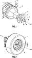
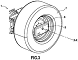
- Figures 1, 2 and 3 present different views of a vehicle wheel structure according to an aspect of the present disclosure.
- FIGS represent different views that show the structure of the components of an example embodiment of the present disclosure. Components are progressively added from figure 1 to figure 3 to illustrate the structure.
- the figures represent a wheel structure for a vehicle, comprising a vehicle frame 1 from which the wheel structure extends.
- the vehicle wheel structure comprises a vehicle axle 2 that extends from the vehicle frame 1.
- the vehicle axle 2 comprises a fixed portion 3 and a mobile portion 4.
- the fixed portion 3 defines a wheel axis X-X, is fixed to the vehicle frame 1 and is immobile with respect to the vehicle frame 1.
- the mobile portion 4 is configured to rotate around the wheel axis X-X with respect to the vehicle frame 1.
- Different components of the structure are part of the fixed portion 3 or of the mobile portion 4.
- the wheel structure includes a wheel engine for instance such as a hydraulic engine
- a fixed part of the wheel engine is part of the fixed portion 3
- a mobile part of the hydraulic engine is part of the mobile portion 4.
- the mobile portion 4 comprises a shaft transmission part 5, which defines a support for a wheel rim 6.
- the wheel rim 6 is assembled to the shaft transmission part 5, for instance with bolts, which ensure that the wheel rim 6 can rotate around the wheel axis X-X.
- the wheel rim 6 supports a tire 7.
- the shaft transmission part 5 can for instance be coupled to a shaft that provides a torque to rotate the wheel in case of a drive wheel, or coupled to the fixed portion 3 by rotating means such as a bearing in case of a free wheel.
- the fixed portion 3 further comprises a support part 34, which extends beyond the shaft transmission part 5 along the wheel axis X-X, so as to protrude on an outside side of the transmission part 5, which means on a side of the transmission part 5 that is on the opposite side from the vehicle frame 1.
- This support part 34 extends along the wheel axis X-X, and is fixed with respect to the frame.
- the support part 34 defines a weight receiving portion adapted to support a wheel weight.
- the wheel weight 8 is assembled on the support part 34, so as to be located at an outer end of the vehicle axle.
- the wheel weight 8 is therefore arranged along the wheel axis X-X, and is fixed with respect to the vehicle frame 1.
- the wheel weight 8 is therefore not a mobile part of the vehicle when the vehicle moves. This addresses the issues related to the rotation of the wheel weight that are present in the common wheel weight structures. Indeed, having a wheel weight which is fixed with respect to the vehicle frame prevents the risks associated with the rotation of the wheel weight in the case where the vehicle moves at a relatively high speed.
- having the wheel weight 8 located at a free end of the vehicle axle provides an easy access to the wheel weight 8 for maintenance operations, or when a user wishes to remove or change the wheel weight 8.
- the installation or the removal of the wheel weight can be done either manually or with a handling tool, depending for instance on the weight of the wheel weight.
- the support part 34 typically presents a shape that is not a shape of revolution around the wheel axis X-X. In the illustrated embodiment, the support part 34 presents a square section.
- the wheel weight 8 presents a through hole whose shape corresponds to that of the support part 34, so that the support part 34 can be inserted within said through hole of the wheel weight 8.
- the support part 34 typically comprises an abutment 35, adapted to restrain the displacement of the wheel weight 8 along the wheel axis X-X along a first direction.
- the displacement of the wheel weight 8 along the wheel axis X-X a second direction opposite to the first direction can for instance be made by using a plate that is assembled at the free end of the support part 34, for instance with a bolt that is inserted in a screw hole 36 arranged at a free end of the support part 34.
- the wheel weight 8 is typically arranged within an inner volume of the wheel rim 6.
- the shape and size of the wheel weight 8 can be modified as long as it fits within the inner diameter of the wheel rim 6.
- the present disclosure also presents the following benefits. Having the wheel weight 8 fixed with respect to the vehicle frame 1 causes no kinetic energy to be generated by the rotation of the wheel weight.
- the balancing process of wheels can be simplified, which therefore significantly simplifies the design of the work vehicle, and has a positive effect on the design costs.
- the replacement of the wheel weight is drastically simplified.
Landscapes
- Engineering & Computer Science (AREA)
- Chemical & Material Sciences (AREA)
- Combustion & Propulsion (AREA)
- Transportation (AREA)
- Mechanical Engineering (AREA)
- Body Structure For Vehicles (AREA)
Abstract
Description
- The present disclosure related to the field of wheel weights for work vehicles, for instance such as tractors.
- The design of wheel for work vehicles requires the design of appropriate wheel weight to ensure a proper balance of the vehicle during various operations.
- To ensure a proper assembly of the wheel weights, they are usually either integrated within the wheel rims, or fixed to specific portions of the wheel rims.
- However, the design of such wheel weight is complex. In addition, new regulations tend to increase the speed that work vehicles such as tractors can reach on the road, for instance up to 50 Km/h or up to 65 Km/h depending on the areas. This increase in the speed limit now leads to new issues in relation to the wheel weights, which are usually designed for lower displacement speeds.
- The present disclosure aims at addressing at least partially these issues.
- The present disclosure is related to a vehicle wheel structure, comprising a vehicle axle extending from a vehicle frame, said vehicle axle comprising a fixed portion which is fixed with respect to the vehicle frame, and a mobile portion which is mobile with respect to the vehicle frame, wherein the fixed portion defines a wheel axis, and the mobile portion is configured to rotate around said wheel axis, the mobile portion comprising a shaft transmission part on which is arranged a wheel rim, said shaft transmission part being rotatable around the wheel axis, the fixed part comprising a support part, which extends beyond the shaft transmission part along the wheel axis, said support part comprising a wheel weight receiving portion which supports a wheel weight, such that the wheel weight is arranged on the wheel axis and is static with respect to the vehicle frame, and the wheel rim is arranged between the wheel weight and the vehicle frame.
- According to an example embodiment, the wheel weight is configured to fit within an inner volume of the wheel rim.
- According to an example embodiment, the wheel weight presents a through hole, the support part is arranged within said through hole, and the wheel weight is fixed in position by a plate arranged at a free end of the support part, said plate being screwed to the support part.
- The support part can comprise an abutment, so that the wheel weight is arranged between said abutment on one hand, and the plate on the other hand, so that the wheel weight is fixed in translation along the wheel axis.
- The support part can present a shape that is not a revolution shape around the wheel axis, and wherein said through hole presents a shape identical to that of the support part.
- The vehicle wheel structure as per the present disclosure can be applied to a work vehicle, for instance to a tractor. The present disclosure therefore also related to a work vehicle, for instance a tractor, that comprises such a vehicle wheel structure.
- Other features, aims and advantages of the invention will be detailed in the following description, which is purely illustrative and should not be interpreted in a limiting way, and which should be read in view of the enclosed drawings, wherein:
-
Figures 1, 2 and3 present a vehicle wheel structure according to an aspect of the present disclosure. - In the various drawings, elements in common are designated by identical numeral references.
-
Figures 1, 2 and3 present different views of a vehicle wheel structure according to an aspect of the present disclosure. - These figures represent different views that show the structure of the components of an example embodiment of the present disclosure. Components are progressively added from
figure 1 to figure 3 to illustrate the structure. - The figures represent a wheel structure for a vehicle, comprising a
vehicle frame 1 from which the wheel structure extends. - The vehicle wheel structure comprises a
vehicle axle 2 that extends from thevehicle frame 1. Thevehicle axle 2 comprises afixed portion 3 and amobile portion 4. - The
fixed portion 3 defines a wheel axis X-X, is fixed to thevehicle frame 1 and is immobile with respect to thevehicle frame 1. - The
mobile portion 4 is configured to rotate around the wheel axis X-X with respect to thevehicle frame 1. - Different components of the structure are part of the fixed
portion 3 or of themobile portion 4. For instance, if the wheel structure includes a wheel engine for instance such as a hydraulic engine, then a fixed part of the wheel engine is part of thefixed portion 3, while a mobile part of the hydraulic engine is part of themobile portion 4. - The
mobile portion 4 comprises ashaft transmission part 5, which defines a support for awheel rim 6. Thewheel rim 6 is assembled to theshaft transmission part 5, for instance with bolts, which ensure that thewheel rim 6 can rotate around the wheel axis X-X. Thewheel rim 6 supports a tire 7. Theshaft transmission part 5 can for instance be coupled to a shaft that provides a torque to rotate the wheel in case of a drive wheel, or coupled to the fixedportion 3 by rotating means such as a bearing in case of a free wheel. - The
fixed portion 3 further comprises asupport part 34, which extends beyond theshaft transmission part 5 along the wheel axis X-X, so as to protrude on an outside side of thetransmission part 5, which means on a side of thetransmission part 5 that is on the opposite side from thevehicle frame 1. Thissupport part 34 extends along the wheel axis X-X, and is fixed with respect to the frame. Thesupport part 34 defines a weight receiving portion adapted to support a wheel weight. 8. - The
wheel weight 8 is assembled on thesupport part 34, so as to be located at an outer end of the vehicle axle. Thewheel weight 8 is therefore arranged along the wheel axis X-X, and is fixed with respect to thevehicle frame 1. - The
wheel weight 8 is therefore not a mobile part of the vehicle when the vehicle moves. This addresses the issues related to the rotation of the wheel weight that are present in the common wheel weight structures. Indeed, having a wheel weight which is fixed with respect to the vehicle frame prevents the risks associated with the rotation of the wheel weight in the case where the vehicle moves at a relatively high speed. - In addition, having the
wheel weight 8 located at a free end of the vehicle axle provides an easy access to thewheel weight 8 for maintenance operations, or when a user wishes to remove or change thewheel weight 8. The installation or the removal of the wheel weight can be done either manually or with a handling tool, depending for instance on the weight of the wheel weight. - The
support part 34 typically presents a shape that is not a shape of revolution around the wheel axis X-X. In the illustrated embodiment, thesupport part 34 presents a square section. Thewheel weight 8 presents a through hole whose shape corresponds to that of thesupport part 34, so that thesupport part 34 can be inserted within said through hole of thewheel weight 8. - The
support part 34 typically comprises anabutment 35, adapted to restrain the displacement of thewheel weight 8 along the wheel axis X-X along a first direction. The displacement of thewheel weight 8 along the wheel axis X-X a second direction opposite to the first direction can for instance be made by using a plate that is assembled at the free end of thesupport part 34, for instance with a bolt that is inserted in ascrew hole 36 arranged at a free end of thesupport part 34. - The
wheel weight 8 is typically arranged within an inner volume of thewheel rim 6. - The shape and size of the
wheel weight 8 can be modified as long as it fits within the inner diameter of thewheel rim 6. - In addition to the advantages already described, the present disclosure also presents the following benefits. Having the
wheel weight 8 fixed with respect to thevehicle frame 1 causes no kinetic energy to be generated by the rotation of the wheel weight. - This therefore negates all the disadvantages associated to such kinetic energy, such as a negative impact on the durability of the work vehicle, and also the risks associated with a potential failure of the link of the wheel weight which would turn the wheel weight into a projectile with a high kinetic energy. The present disclosure prevents such risks.
- Furthermore, by using a static wheel weight instead of a rotating wheel weight, the balancing process of wheels can be simplified, which therefore significantly simplifies the design of the work vehicle, and has a positive effect on the design costs. In addition, due to the non-requirement of a balancing process, the replacement of the wheel weight is drastically simplified.
Claims (6)
- A vehicle wheel structure, comprising a vehicle axle (2) extending from a vehicle frame (1), said vehicle axle (2) comprising a fixed portion (3) which is fixed with respect to the vehicle frame (1), and a mobile portion (4) which is mobile with respect to the vehicle frame (1), wherein the fixed portion (3) defines a wheel axis (X-X), and the mobile portion (4) is configured to rotate around said wheel axis (X-X),
the mobile portion (4) comprising a shaft transmission part (5) on which is arranged a wheel rim (6), said shaft transmission part (5) being rotatable around the wheel axis (X-X),
the fixed part (3) comprising a support part (34), which extends beyond the shaft transmission part (5) along the wheel axis (X-X), said support part (34) comprising a wheel weight receiving portion which supports a wheel weight (8), such that the wheel weight (8) is arranged on the wheel axis (X-X) and is static with respect to the vehicle frame (1), and the wheel rim (6) is arranged between the wheel weight (8) and the vehicle frame (1). - The vehicle wheel structure according to claim 1, wherein the wheel weight (8) is configured to fit within an inner volume of the wheel rim (6).
- The vehicle wheel structure according to claim 1 or claim 2, wherein the wheel weight (8) presents a through hole, the support part (34) is arranged within said through hole, and the wheel weight (8) is fixed in position by a plate arranged at a free end of the support part (34), said plate being screwed to the support part (34).
- The vehicle wheel structure according to claim 3, wherein the support part (34) comprises an abutment (35), so that the wheel weight (8) is arranged between said abutment (35) on one hand, and the plate on the other hand, so that the wheel weight (8) is fixed in translation along the wheel axis (X-X).
- The vehicle wheel structure according to any one of claims 3 or 4, wherein the support part (34) presents a shape that is not a revolution shape around the wheel axis (X-X), and wherein said through hole presents a shape identical to that of the support part (34).
- A tractor comprising a vehicle wheel structure according to any one of claims 1 to 5.
Priority Applications (1)
| Application Number | Priority Date | Filing Date | Title |
|---|---|---|---|
| EP20305244.4A EP3878720B1 (en) | 2020-03-09 | 2020-03-09 | Improved wheel weight structure for a work vehicle |
Applications Claiming Priority (1)
| Application Number | Priority Date | Filing Date | Title |
|---|---|---|---|
| EP20305244.4A EP3878720B1 (en) | 2020-03-09 | 2020-03-09 | Improved wheel weight structure for a work vehicle |
Publications (2)
| Publication Number | Publication Date |
|---|---|
| EP3878720A1 true EP3878720A1 (en) | 2021-09-15 |
| EP3878720B1 EP3878720B1 (en) | 2022-05-11 |
Family
ID=69960586
Family Applications (1)
| Application Number | Title | Priority Date | Filing Date |
|---|---|---|---|
| EP20305244.4A Active EP3878720B1 (en) | 2020-03-09 | 2020-03-09 | Improved wheel weight structure for a work vehicle |
Country Status (1)
| Country | Link |
|---|---|
| EP (1) | EP3878720B1 (en) |
Families Citing this family (1)
| Publication number | Priority date | Publication date | Assignee | Title |
|---|---|---|---|---|
| GB202311948D0 (en) * | 2023-08-03 | 2023-09-20 | Agco Int Gmbh | Weighting a vehicle |
Citations (3)
| Publication number | Priority date | Publication date | Assignee | Title |
|---|---|---|---|---|
| DE102014202074A1 (en) * | 2014-02-05 | 2015-08-06 | Deere & Company | Radzusatzgewicht |
| KR20170084728A (en) * | 2016-01-12 | 2017-07-21 | 전주대학교 산학협력단 | The tractor for wheel pick-up equipment |
| EP3409502A1 (en) * | 2017-06-01 | 2018-12-05 | Deere & Company | Additional wheel weight for commercial vehicle |
-
2020
- 2020-03-09 EP EP20305244.4A patent/EP3878720B1/en active Active
Patent Citations (3)
| Publication number | Priority date | Publication date | Assignee | Title |
|---|---|---|---|---|
| DE102014202074A1 (en) * | 2014-02-05 | 2015-08-06 | Deere & Company | Radzusatzgewicht |
| KR20170084728A (en) * | 2016-01-12 | 2017-07-21 | 전주대학교 산학협력단 | The tractor for wheel pick-up equipment |
| EP3409502A1 (en) * | 2017-06-01 | 2018-12-05 | Deere & Company | Additional wheel weight for commercial vehicle |
Also Published As
| Publication number | Publication date |
|---|---|
| EP3878720B1 (en) | 2022-05-11 |
Similar Documents
| Publication | Publication Date | Title |
|---|---|---|
| US20180272855A1 (en) | In-wheel motor drive device and connection structure between in-wheel motor drive device and suspension device | |
| US20150210154A1 (en) | Suspension structure for in-wheel motor drive device | |
| US6588538B2 (en) | Wheel and final drive assembly for a ground driven work machine | |
| EP3287306B1 (en) | Vehicle suspension structure | |
| EP3878720B1 (en) | Improved wheel weight structure for a work vehicle | |
| JP2013023202A (en) | Electric wheel | |
| EP1342591B1 (en) | Independently rotating wheels | |
| JP4730078B2 (en) | In-wheel motor | |
| CN103112313A (en) | Wheel rim drive device | |
| CN113335167B (en) | Front wheel assembly and heavy vehicle | |
| US4744588A (en) | Suspension system | |
| JP5616239B2 (en) | Traveling vehicle | |
| US2871965A (en) | Steering drive axle | |
| US10710406B1 (en) | Assembly for a vehicle axle including a differential | |
| CN113232504B (en) | Motor, chassis structure and vehicle | |
| CN211592243U (en) | Heavy-duty large-speed-ratio electric tractor drive axle | |
| CN110861490B (en) | Driving axle of heavy large-speed-ratio electric tractor | |
| EP3789209B1 (en) | Braking system for twin tire axles | |
| US4089383A (en) | Power driven centerline steering safety axle wheel assembly with disc brake | |
| JP2009222171A (en) | Disc brake device of working vehicle | |
| CN207644074U (en) | It is applicable in double transverse arm suspension chassis front axle assy | |
| CN107276303A (en) | A kind of mining self-unloading vehicle wheel reducer and traction electric machine attachment structure | |
| US20250282427A1 (en) | Wheel for a motor vehicle and method for manufacturing a fairing for said wheel | |
| CN221457586U (en) | Vehicle braking structure | |
| CN205651900U (en) | Transaxle is from aligning semi -axis |
Legal Events
| Date | Code | Title | Description |
|---|---|---|---|
| PUAI | Public reference made under article 153(3) epc to a published international application that has entered the european phase |
Free format text: ORIGINAL CODE: 0009012 |
|
| STAA | Information on the status of an ep patent application or granted ep patent |
Free format text: STATUS: THE APPLICATION HAS BEEN PUBLISHED |
|
| AK | Designated contracting states |
Kind code of ref document: A1 Designated state(s): AL AT BE BG CH CY CZ DE DK EE ES FI FR GB GR HR HU IE IS IT LI LT LU LV MC MK MT NL NO PL PT RO RS SE SI SK SM TR |
|
| STAA | Information on the status of an ep patent application or granted ep patent |
Free format text: STATUS: REQUEST FOR EXAMINATION WAS MADE |
|
| 17P | Request for examination filed |
Effective date: 20211014 |
|
| RBV | Designated contracting states (corrected) |
Designated state(s): AL AT BE BG CH CY CZ DE DK EE ES FI FR GB GR HR HU IE IS IT LI LT LU LV MC MK MT NL NO PL PT RO RS SE SI SK SM TR |
|
| GRAP | Despatch of communication of intention to grant a patent |
Free format text: ORIGINAL CODE: EPIDOSNIGR1 |
|
| STAA | Information on the status of an ep patent application or granted ep patent |
Free format text: STATUS: GRANT OF PATENT IS INTENDED |
|
| GRAS | Grant fee paid |
Free format text: ORIGINAL CODE: EPIDOSNIGR3 |
|
| RIC1 | Information provided on ipc code assigned before grant |
Ipc: B62D 49/06 20060101AFI20220215BHEP |
|
| INTG | Intention to grant announced |
Effective date: 20220301 |
|
| GRAA | (expected) grant |
Free format text: ORIGINAL CODE: 0009210 |
|
| STAA | Information on the status of an ep patent application or granted ep patent |
Free format text: STATUS: THE PATENT HAS BEEN GRANTED |
|
| AK | Designated contracting states |
Kind code of ref document: B1 Designated state(s): AL AT BE BG CH CY CZ DE DK EE ES FI FR GB GR HR HU IE IS IT LI LT LU LV MC MK MT NL NO PL PT RO RS SE SI SK SM TR |
|
| REG | Reference to a national code |
Ref country code: GB Ref legal event code: FG4D |
|
| REG | Reference to a national code |
Ref country code: CH Ref legal event code: EP |
|
| REG | Reference to a national code |
Ref country code: AT Ref legal event code: REF Ref document number: 1491205 Country of ref document: AT Kind code of ref document: T Effective date: 20220515 |
|
| REG | Reference to a national code |
Ref country code: DE Ref legal event code: R096 Ref document number: 602020003173 Country of ref document: DE |
|
| REG | Reference to a national code |
Ref country code: IE Ref legal event code: FG4D |
|
| REG | Reference to a national code |
Ref country code: LT Ref legal event code: MG9D |
|
| REG | Reference to a national code |
Ref country code: NL Ref legal event code: MP Effective date: 20220511 |
|
| REG | Reference to a national code |
Ref country code: AT Ref legal event code: MK05 Ref document number: 1491205 Country of ref document: AT Kind code of ref document: T Effective date: 20220511 |
|
| PG25 | Lapsed in a contracting state [announced via postgrant information from national office to epo] |
Ref country code: SE Free format text: LAPSE BECAUSE OF FAILURE TO SUBMIT A TRANSLATION OF THE DESCRIPTION OR TO PAY THE FEE WITHIN THE PRESCRIBED TIME-LIMIT Effective date: 20220511 Ref country code: PT Free format text: LAPSE BECAUSE OF FAILURE TO SUBMIT A TRANSLATION OF THE DESCRIPTION OR TO PAY THE FEE WITHIN THE PRESCRIBED TIME-LIMIT Effective date: 20220912 Ref country code: NO Free format text: LAPSE BECAUSE OF FAILURE TO SUBMIT A TRANSLATION OF THE DESCRIPTION OR TO PAY THE FEE WITHIN THE PRESCRIBED TIME-LIMIT Effective date: 20220811 Ref country code: NL Free format text: LAPSE BECAUSE OF FAILURE TO SUBMIT A TRANSLATION OF THE DESCRIPTION OR TO PAY THE FEE WITHIN THE PRESCRIBED TIME-LIMIT Effective date: 20220511 Ref country code: LT Free format text: LAPSE BECAUSE OF FAILURE TO SUBMIT A TRANSLATION OF THE DESCRIPTION OR TO PAY THE FEE WITHIN THE PRESCRIBED TIME-LIMIT Effective date: 20220511 Ref country code: HR Free format text: LAPSE BECAUSE OF FAILURE TO SUBMIT A TRANSLATION OF THE DESCRIPTION OR TO PAY THE FEE WITHIN THE PRESCRIBED TIME-LIMIT Effective date: 20220511 Ref country code: GR Free format text: LAPSE BECAUSE OF FAILURE TO SUBMIT A TRANSLATION OF THE DESCRIPTION OR TO PAY THE FEE WITHIN THE PRESCRIBED TIME-LIMIT Effective date: 20220812 Ref country code: FI Free format text: LAPSE BECAUSE OF FAILURE TO SUBMIT A TRANSLATION OF THE DESCRIPTION OR TO PAY THE FEE WITHIN THE PRESCRIBED TIME-LIMIT Effective date: 20220511 Ref country code: BG Free format text: LAPSE BECAUSE OF FAILURE TO SUBMIT A TRANSLATION OF THE DESCRIPTION OR TO PAY THE FEE WITHIN THE PRESCRIBED TIME-LIMIT Effective date: 20220811 Ref country code: AT Free format text: LAPSE BECAUSE OF FAILURE TO SUBMIT A TRANSLATION OF THE DESCRIPTION OR TO PAY THE FEE WITHIN THE PRESCRIBED TIME-LIMIT Effective date: 20220511 |
|
| PG25 | Lapsed in a contracting state [announced via postgrant information from national office to epo] |
Ref country code: RS Free format text: LAPSE BECAUSE OF FAILURE TO SUBMIT A TRANSLATION OF THE DESCRIPTION OR TO PAY THE FEE WITHIN THE PRESCRIBED TIME-LIMIT Effective date: 20220511 Ref country code: PL Free format text: LAPSE BECAUSE OF FAILURE TO SUBMIT A TRANSLATION OF THE DESCRIPTION OR TO PAY THE FEE WITHIN THE PRESCRIBED TIME-LIMIT Effective date: 20220511 Ref country code: LV Free format text: LAPSE BECAUSE OF FAILURE TO SUBMIT A TRANSLATION OF THE DESCRIPTION OR TO PAY THE FEE WITHIN THE PRESCRIBED TIME-LIMIT Effective date: 20220511 Ref country code: IS Free format text: LAPSE BECAUSE OF FAILURE TO SUBMIT A TRANSLATION OF THE DESCRIPTION OR TO PAY THE FEE WITHIN THE PRESCRIBED TIME-LIMIT Effective date: 20220911 |
|
| PG25 | Lapsed in a contracting state [announced via postgrant information from national office to epo] |
Ref country code: SM Free format text: LAPSE BECAUSE OF FAILURE TO SUBMIT A TRANSLATION OF THE DESCRIPTION OR TO PAY THE FEE WITHIN THE PRESCRIBED TIME-LIMIT Effective date: 20220511 Ref country code: SK Free format text: LAPSE BECAUSE OF FAILURE TO SUBMIT A TRANSLATION OF THE DESCRIPTION OR TO PAY THE FEE WITHIN THE PRESCRIBED TIME-LIMIT Effective date: 20220511 Ref country code: RO Free format text: LAPSE BECAUSE OF FAILURE TO SUBMIT A TRANSLATION OF THE DESCRIPTION OR TO PAY THE FEE WITHIN THE PRESCRIBED TIME-LIMIT Effective date: 20220511 Ref country code: ES Free format text: LAPSE BECAUSE OF FAILURE TO SUBMIT A TRANSLATION OF THE DESCRIPTION OR TO PAY THE FEE WITHIN THE PRESCRIBED TIME-LIMIT Effective date: 20220511 Ref country code: EE Free format text: LAPSE BECAUSE OF FAILURE TO SUBMIT A TRANSLATION OF THE DESCRIPTION OR TO PAY THE FEE WITHIN THE PRESCRIBED TIME-LIMIT Effective date: 20220511 Ref country code: DK Free format text: LAPSE BECAUSE OF FAILURE TO SUBMIT A TRANSLATION OF THE DESCRIPTION OR TO PAY THE FEE WITHIN THE PRESCRIBED TIME-LIMIT Effective date: 20220511 Ref country code: CZ Free format text: LAPSE BECAUSE OF FAILURE TO SUBMIT A TRANSLATION OF THE DESCRIPTION OR TO PAY THE FEE WITHIN THE PRESCRIBED TIME-LIMIT Effective date: 20220511 |
|
| REG | Reference to a national code |
Ref country code: DE Ref legal event code: R097 Ref document number: 602020003173 Country of ref document: DE |
|
| REG | Reference to a national code |
Ref country code: DE Ref legal event code: R082 Ref document number: 602020003173 Country of ref document: DE Representative=s name: CBDL PATENTANWAELTE GBR, DE Ref country code: DE Ref legal event code: R082 Ref document number: 602020003173 Country of ref document: DE Representative=s name: CBDL PATENTANWAELTE EGBR, DE |
|
| PLBE | No opposition filed within time limit |
Free format text: ORIGINAL CODE: 0009261 |
|
| STAA | Information on the status of an ep patent application or granted ep patent |
Free format text: STATUS: NO OPPOSITION FILED WITHIN TIME LIMIT |
|
| PG25 | Lapsed in a contracting state [announced via postgrant information from national office to epo] |
Ref country code: AL Free format text: LAPSE BECAUSE OF FAILURE TO SUBMIT A TRANSLATION OF THE DESCRIPTION OR TO PAY THE FEE WITHIN THE PRESCRIBED TIME-LIMIT Effective date: 20220511 |
|
| 26N | No opposition filed |
Effective date: 20230214 |
|
| PG25 | Lapsed in a contracting state [announced via postgrant information from national office to epo] |
Ref country code: MC Free format text: LAPSE BECAUSE OF FAILURE TO SUBMIT A TRANSLATION OF THE DESCRIPTION OR TO PAY THE FEE WITHIN THE PRESCRIBED TIME-LIMIT Effective date: 20220511 |
|
| REG | Reference to a national code |
Ref country code: CH Ref legal event code: PL |
|
| REG | Reference to a national code |
Ref country code: BE Ref legal event code: MM Effective date: 20230331 |
|
| PG25 | Lapsed in a contracting state [announced via postgrant information from national office to epo] |
Ref country code: LU Free format text: LAPSE BECAUSE OF NON-PAYMENT OF DUE FEES Effective date: 20230309 |
|
| REG | Reference to a national code |
Ref country code: IE Ref legal event code: MM4A |
|
| PG25 | Lapsed in a contracting state [announced via postgrant information from national office to epo] |
Ref country code: LI Free format text: LAPSE BECAUSE OF NON-PAYMENT OF DUE FEES Effective date: 20230331 Ref country code: IT Free format text: LAPSE BECAUSE OF FAILURE TO SUBMIT A TRANSLATION OF THE DESCRIPTION OR TO PAY THE FEE WITHIN THE PRESCRIBED TIME-LIMIT Effective date: 20220511 Ref country code: IE Free format text: LAPSE BECAUSE OF NON-PAYMENT OF DUE FEES Effective date: 20230309 Ref country code: CH Free format text: LAPSE BECAUSE OF NON-PAYMENT OF DUE FEES Effective date: 20230331 |
|
| PG25 | Lapsed in a contracting state [announced via postgrant information from national office to epo] |
Ref country code: BE Free format text: LAPSE BECAUSE OF NON-PAYMENT OF DUE FEES Effective date: 20230331 |
|
| PG25 | Lapsed in a contracting state [announced via postgrant information from national office to epo] |
Ref country code: BG Free format text: LAPSE BECAUSE OF FAILURE TO SUBMIT A TRANSLATION OF THE DESCRIPTION OR TO PAY THE FEE WITHIN THE PRESCRIBED TIME-LIMIT Effective date: 20220511 |
|
| GBPC | Gb: european patent ceased through non-payment of renewal fee |
Effective date: 20240309 |
|
| PG25 | Lapsed in a contracting state [announced via postgrant information from national office to epo] |
Ref country code: BG Free format text: LAPSE BECAUSE OF FAILURE TO SUBMIT A TRANSLATION OF THE DESCRIPTION OR TO PAY THE FEE WITHIN THE PRESCRIBED TIME-LIMIT Effective date: 20220511 |
|
| PG25 | Lapsed in a contracting state [announced via postgrant information from national office to epo] |
Ref country code: GB Free format text: LAPSE BECAUSE OF NON-PAYMENT OF DUE FEES Effective date: 20240309 |
|
| PG25 | Lapsed in a contracting state [announced via postgrant information from national office to epo] |
Ref country code: GB Free format text: LAPSE BECAUSE OF NON-PAYMENT OF DUE FEES Effective date: 20240309 |
|
| PG25 | Lapsed in a contracting state [announced via postgrant information from national office to epo] |
Ref country code: CY Free format text: LAPSE BECAUSE OF FAILURE TO SUBMIT A TRANSLATION OF THE DESCRIPTION OR TO PAY THE FEE WITHIN THE PRESCRIBED TIME-LIMIT; INVALID AB INITIO Effective date: 20200309 |
|
| PG25 | Lapsed in a contracting state [announced via postgrant information from national office to epo] |
Ref country code: HU Free format text: LAPSE BECAUSE OF FAILURE TO SUBMIT A TRANSLATION OF THE DESCRIPTION OR TO PAY THE FEE WITHIN THE PRESCRIBED TIME-LIMIT; INVALID AB INITIO Effective date: 20200309 |
|
| PG25 | Lapsed in a contracting state [announced via postgrant information from national office to epo] |
Ref country code: TR Free format text: LAPSE BECAUSE OF FAILURE TO SUBMIT A TRANSLATION OF THE DESCRIPTION OR TO PAY THE FEE WITHIN THE PRESCRIBED TIME-LIMIT Effective date: 20220511 |
|
| PG25 | Lapsed in a contracting state [announced via postgrant information from national office to epo] |
Ref country code: SI Free format text: LAPSE BECAUSE OF FAILURE TO SUBMIT A TRANSLATION OF THE DESCRIPTION OR TO PAY THE FEE WITHIN THE PRESCRIBED TIME-LIMIT Effective date: 20220511 |
|
| PGFP | Annual fee paid to national office [announced via postgrant information from national office to epo] |
Ref country code: DE Payment date: 20260128 Year of fee payment: 7 |
|
| PGFP | Annual fee paid to national office [announced via postgrant information from national office to epo] |
Ref country code: FR Payment date: 20260209 Year of fee payment: 7 |