EP3878556A1 - System for automated permeation of a biological material and method of using same - Google Patents
System for automated permeation of a biological material and method of using same Download PDFInfo
- Publication number
- EP3878556A1 EP3878556A1 EP21157723.4A EP21157723A EP3878556A1 EP 3878556 A1 EP3878556 A1 EP 3878556A1 EP 21157723 A EP21157723 A EP 21157723A EP 3878556 A1 EP3878556 A1 EP 3878556A1
- Authority
- EP
- European Patent Office
- Prior art keywords
- reservoir
- lower portion
- upper portion
- groove
- coupled
- Prior art date
- Legal status (The legal status is an assumption and is not a legal conclusion. Google has not performed a legal analysis and makes no representation as to the accuracy of the status listed.)
- Pending
Links
Images


Classifications
-
- B—PERFORMING OPERATIONS; TRANSPORTING
- B01—PHYSICAL OR CHEMICAL PROCESSES OR APPARATUS IN GENERAL
- B01L—CHEMICAL OR PHYSICAL LABORATORY APPARATUS FOR GENERAL USE
- B01L3/00—Containers or dishes for laboratory use, e.g. laboratory glassware; Droppers
- B01L3/50—Containers for the purpose of retaining a material to be analysed, e.g. test tubes
- B01L3/502—Containers for the purpose of retaining a material to be analysed, e.g. test tubes with fluid transport, e.g. in multi-compartment structures
- B01L3/5027—Containers for the purpose of retaining a material to be analysed, e.g. test tubes with fluid transport, e.g. in multi-compartment structures by integrated microfluidic structures, i.e. dimensions of channels and chambers are such that surface tension forces are important, e.g. lab-on-a-chip
- B01L3/502761—Containers for the purpose of retaining a material to be analysed, e.g. test tubes with fluid transport, e.g. in multi-compartment structures by integrated microfluidic structures, i.e. dimensions of channels and chambers are such that surface tension forces are important, e.g. lab-on-a-chip specially adapted for handling suspended solids or molecules independently from the bulk fluid flow, e.g. for trapping or sorting beads or physically stretching molecules
-
- A—HUMAN NECESSITIES
- A01—AGRICULTURE; FORESTRY; ANIMAL HUSBANDRY; HUNTING; TRAPPING; FISHING
- A01N—PRESERVATION OF BODIES OF HUMANS OR ANIMALS OR PLANTS OR PARTS THEREOF; BIOCIDES, e.g. AS DISINFECTANTS, AS PESTICIDES OR AS HERBICIDES; PEST REPELLANTS OR ATTRACTANTS; PLANT GROWTH REGULATORS
- A01N1/00—Preservation of bodies of humans or animals, or parts thereof
- A01N1/10—Preservation of living parts
- A01N1/14—Mechanical aspects of preservation; Apparatus or containers therefor
- A01N1/146—Non-refrigerated containers specially adapted for transporting or storing living parts whilst preserving
- A01N1/147—Carriers for immersion in cryogenic fluid for slow freezing or vitrification
-
- A—HUMAN NECESSITIES
- A01—AGRICULTURE; FORESTRY; ANIMAL HUSBANDRY; HUNTING; TRAPPING; FISHING
- A01N—PRESERVATION OF BODIES OF HUMANS OR ANIMALS OR PLANTS OR PARTS THEREOF; BIOCIDES, e.g. AS DISINFECTANTS, AS PESTICIDES OR AS HERBICIDES; PEST REPELLANTS OR ATTRACTANTS; PLANT GROWTH REGULATORS
- A01N1/00—Preservation of bodies of humans or animals, or parts thereof
- A01N1/10—Preservation of living parts
- A01N1/12—Chemical aspects of preservation
- A01N1/122—Preservation or perfusion media
- A01N1/125—Freeze protecting agents, e.g. cryoprotectants or osmolarity regulators
-
- A—HUMAN NECESSITIES
- A01—AGRICULTURE; FORESTRY; ANIMAL HUSBANDRY; HUNTING; TRAPPING; FISHING
- A01N—PRESERVATION OF BODIES OF HUMANS OR ANIMALS OR PLANTS OR PARTS THEREOF; BIOCIDES, e.g. AS DISINFECTANTS, AS PESTICIDES OR AS HERBICIDES; PEST REPELLANTS OR ATTRACTANTS; PLANT GROWTH REGULATORS
- A01N1/00—Preservation of bodies of humans or animals, or parts thereof
- A01N1/10—Preservation of living parts
- A01N1/14—Mechanical aspects of preservation; Apparatus or containers therefor
- A01N1/142—Apparatus
-
- B—PERFORMING OPERATIONS; TRANSPORTING
- B01—PHYSICAL OR CHEMICAL PROCESSES OR APPARATUS IN GENERAL
- B01L—CHEMICAL OR PHYSICAL LABORATORY APPARATUS FOR GENERAL USE
- B01L3/00—Containers or dishes for laboratory use, e.g. laboratory glassware; Droppers
- B01L3/50—Containers for the purpose of retaining a material to be analysed, e.g. test tubes
- B01L3/502—Containers for the purpose of retaining a material to be analysed, e.g. test tubes with fluid transport, e.g. in multi-compartment structures
-
- B—PERFORMING OPERATIONS; TRANSPORTING
- B01—PHYSICAL OR CHEMICAL PROCESSES OR APPARATUS IN GENERAL
- B01L—CHEMICAL OR PHYSICAL LABORATORY APPARATUS FOR GENERAL USE
- B01L2200/00—Solutions for specific problems relating to chemical or physical laboratory apparatus
- B01L2200/06—Fluid handling related problems
- B01L2200/0647—Handling flowable solids, e.g. microscopic beads, cells, particles
- B01L2200/0668—Trapping microscopic beads
-
- B—PERFORMING OPERATIONS; TRANSPORTING
- B01—PHYSICAL OR CHEMICAL PROCESSES OR APPARATUS IN GENERAL
- B01L—CHEMICAL OR PHYSICAL LABORATORY APPARATUS FOR GENERAL USE
- B01L2200/00—Solutions for specific problems relating to chemical or physical laboratory apparatus
- B01L2200/16—Reagents, handling or storing thereof
-
- B—PERFORMING OPERATIONS; TRANSPORTING
- B01—PHYSICAL OR CHEMICAL PROCESSES OR APPARATUS IN GENERAL
- B01L—CHEMICAL OR PHYSICAL LABORATORY APPARATUS FOR GENERAL USE
- B01L2300/00—Additional constructional details
- B01L2300/04—Closures and closing means
- B01L2300/041—Connecting closures to device or container
- B01L2300/043—Hinged closures
-
- B—PERFORMING OPERATIONS; TRANSPORTING
- B01—PHYSICAL OR CHEMICAL PROCESSES OR APPARATUS IN GENERAL
- B01L—CHEMICAL OR PHYSICAL LABORATORY APPARATUS FOR GENERAL USE
- B01L2400/00—Moving or stopping fluids
- B01L2400/04—Moving fluids with specific forces or mechanical means
- B01L2400/0475—Moving fluids with specific forces or mechanical means specific mechanical means and fluid pressure
- B01L2400/0487—Moving fluids with specific forces or mechanical means specific mechanical means and fluid pressure fluid pressure, pneumatics
Definitions
- the cells In order to cryopreserve cells through vitrification, the cells must be permeated into vitrification solutions, consisting on media buffer with a high concentration of cryoprotectant agents that help the cell survive the vitrification process.
- the current procedure involves a highly skilled user manually aspirating and injecting the cells into various solutions of media, with increasing concentrations of cryoprotectant agents until the final concentration is reached. This procedure requires a significant amount of time by the user.
- the cells of interest can range in size from 50 to 200 microns, creating the need for the procedure to be performed under a microscope using micromanipulation pipettes operated by hand. Successful permeation of cells in the vitrification solutions requires careful timing and precision handling of micropipettes
- One general aspect of the present disclosure includes a device for permeation of a biological material, including: a lower portion; and an upper portion configured to be releasably coupled to the lower portion, where the lower portion includes a groove configured to receivingly support a biological material, where the lower portion and the upper portion are coupled such that a first reservoir and a second reservoir are formed collectively by the lower portion and the upper portion, and where the first reservoir, the second reservoir, and the groove are in fluid communication with each other.
- kits for permeation of a biological material including: a first device including a lower portion and an upper portion configured to be releasably coupled to the lower portion; and a second device configured for receivingly support the first device, where the second device includes a cavity and at least one arm movable between an open position and a closed position, and where when the at least one arm is in the closed position, the first device is secured within the cavity with the upper portion of the first device sealingly engaging the lower portion of the first device.
- Another general aspect of the present disclosure includes a method of permeating a biological material using a device including a lower portion and an upper portion configured to be releasably coupled to the lower portion to collectively form a first reservoir, a second reservoir, and a channel, the lower portion including a groove in fluid communication with the first and second reservoirs and the channel, including: placing a biological material in the groove of the lower portion; coupling the upper portion to the lower portion; placing a first liquid into the first reservoir; and applying a first suction to the second reservoir such that the first liquid flows along the channel into the groove.
- the system 10 may include a lower portion 12 and an upper portion 14 configured to be releasably coupled to the lower portion 12.
- the lower portion 12 may include a top surface 16, a bottom surface 18, and a groove 20 extending from the top surface 16 towards the bottom surface 18.
- the groove 20 may be configured to receivingly support a biological material 22 (e.g., as shown in FIGS. 1-2 ).
- the biological material 22 may be various kinds of biological materials, such as an embryo or an oocyte.
- the groove 20 may be configured to accommodate the various kinds of biological materials, such that the biological material 22 may be placed therein to be permeated with desired liquids, as discussed in greater detail below.
- the groove 20 may be varied, as desired and/or needed, without departing from the scope of the present invention.
- the groove 20 may include a first section 24 and a second section 26, where the first section 24 may extend from the top surface 16 of the lower portion 12 to an intermediate surface 28 of the lower portion 12 and the second section 26 may extend from the intermediate surface 28 of the lower portion 12 towards the bottom surface 18 of the lower portion 12.
- This embodiment increases the depth of the groove 20 and creates another channel over the biological material 22, which may be advantageous for slowing down the permeation rate of a solution into the biological material 22, as discussed in greater detail below.
- a vitrification stick when the system 10 is used to prepare the biological material 22 for vitrification (e.g., cryopreservation of the biological material 22 by permeating the biological material 22 with cryoprotectant solutions), a vitrification stick, as shown in FIG. 6 , may be used as the lower portion 12 of the system 10, which may allow the user to permeate the biological material 22 directly on the vitrification stick, such that when the permeation process is completed, the vitrification stick supporting the biological material 22 may be directly placed into a vitrification solution, such as liquid nitrogen, for vitrification of the biological material 22 without additional transfer of the biological material 22.
- a vitrification solution such as liquid nitrogen
- the upper portion 14 may include an upper surface 30 and a lower surface 32, where the lower surface 32 may include a first opening 34 and a second opening 36.
- the upper portion 14 may also include a first protrusion 38 extending outwardly from the upper surface 30 of the upper portion 14 and in fluid communication with the first opening 34 and a second protrusion 40 extending outwardly from the upper surface 30 of the upper portion 14 and in fluid communication with the second opening 36. As shown in FIGS.
- the lower portion 12 and the upper portion 14 are configured such that when they are coupled together (e.g., placing the upper portion 14 upon the lower portion 12), the first protrusion 38 and the top surface 16 of the lower portion 12 may collectively form a first reservoir 42 and the second protrusion 40 and the top surface 16 of the lower portion 12 may collectively form a second reservoir 44.
- the first reservoir 42, the second reservoir 44, and the groove 20 may be in fluid communication with each other, and the first and second reservoirs 42 and 44 may be configured such that liquids may be directed into and out of the system 10 (collectively formed by the lower and upper portions 12 and 14) via the first and second reservoirs 42 and 44.
- the groove 20 may be disposed between the first and second reservoirs 42 and 44, and liquids may be directed into or out of the groove 20 through the first reservoir 42 or the second reservoir 44, as discussed in greater detail below.
- the lower surface 32 of the upper portion 14 may include a slot 46 disposed between and in fluid communication with the first and second openings 34 and 36.
- the slot 46 may extend from the lower surface 32 of the upper portion 14 towards the upper surface 30 of the upper portion 14.
- the slot 46 may be configured such that when the upper portion 14 is coupled to (e.g., placed upon) the lower portion 12, the slot 46 and the top surface 16 of the lower portion 12 may collectively form a channel 48, as shown in FIG. 1 , where the channel 48 is in fluid communication with the groove 20 and the first and second reservoirs 42 and 44.
- the groove 20 may be disposed in registry with the channel 48.
- the lower and upper portions 12 and 14 may be configured such that when the upper portion 14 is coupled to (e.g., placed upon) the lower portion 12, the top surface 16 of the lower portion 12 sealingly engages the lower surface 32 of the upper portion 14, thereby sealing the channel 48, such that liquids introduced into the system 10, through one of the first and second reservoirs 42 and 44, may flow along the channel 48 and past the groove 20, as discussed in greater detail below.
- the lower and upper portions 12 and 14 may remain coupled (closed) by using mechanical clips, magnets, or any other closing mechanism that would create a seal (pressure seal) in the fluid, generically represented in FIG.
- connection means 47a/47b/47c/47d which can include any connection-enhancers referenced herein, alone or in combination with each other (including, without limit, one or more of magnets, clips, flexible seals, adhesive material/structure, and hinges) (e.g., only one clip may be needed when the lower and upper portions 12 and 14 are hinged together).
- the lower and upper portions 12 and 14 may be magnetized and create a seal based on this.
- the upper portion 14 may have a non-toxic rubber or silicone liner configured to facilitate sealing the channel 48. In some embodiments, as shown in FIGS.
- the upper portion 14 may include at least one leg 50 (e.g., a plurality of legs; when the upper portion 14 and the lower portion 12 are hinged together, only one leg 50 may be needed) extending outwardly from the lower surface 32 of the upper portion 14,
- the lower portion 12 may include at least one aperture 52 (e.g., a plurality of apertures) configured for receiving the at least one leg 50 (e.g., a plurality of apertures are configured for receiving a plurality of legs, respectively) when the upper portion 14 is coupled to the lower portion 12.
- This embodiment is advantageous for facilitating aligning the lower and upper portions 12 and 14 (e.g., when the lower and upper portions 12 and 14 are not hinged together) before closing, thereby creating a desired sealing of the channel 48.
- the biological material 22 may be placed in the groove before the upper portion 14 is coupled to (e.g., placed upon) the lower portion 12.
- liquids may be introduced into the system 10 through one of the first and second reservoirs 42 and 44 (e.g., liquids are introduced into the first reservoir 42).
- the other reservoir (e.g., the reservoir that was not used for introducing liquids into the system 10; the second reservoir 44) may be configured to be coupled to a suction device such that suction applied to the other reservoir (e.g., the second reservoir 44) may cause the liquids to flow along/in the channel 48 and into the groove 20, and may further cause the liquids to flow past the groove 20, along/in the channel 48, and towards/into the other reservoir (e.g., the second reservoir 44).
- the reservoir that was used for introducing liquids into the system 10 may be configured to be coupled to a positive pressure device such that positive pressure applied to the reservoir that was used for introducing liquids into the system 10 (e.g., the first reservoir 42) may cause the liquids to flow along/in the channel 48 and into the groove 20, and may further cause the liquids to flow past the groove 20, along/in the channel 48, and towards/into the other reservoir (e.g., the second reservoir 44).
- the first reservoir 42 may be configured to allow liquids to be introduced into the system through the first reservoir 42.
- the first reservoir 42 may be configured to be coupled to a positive pressure device and/or the second reservoir 44 may be configured to be coupled to a suction device such that positive pressure applied to the first reservoir 42 and/or suction applied to the second reservoir 44 may cause liquids introduced into the system 10 through the first reservoir 42 to flow along the channel 48, and into the groove 20, and may further cause the liquids to flow past the groove 20, along the channel 48, and into the second reservoir 44, such that the biological material 22 disposed in the groove 20 may be permeated with the liquids passing through the biological material 22, as discussed in greater detail below.
- the second reservoir 44 may also be used as a petri dish in the event that the biological material 22 flows out of the groove 20 and into the second reservoir 44.
- the system 10 may also include a lid 54 configured to be removably coupled to the second reservoir 44, such that a user may remove the lid 54 and get access to the second reservoir 44 to retrieve the biological material 22 that flows into the second reservoir 44, when needed. It will be appreciated that the system 10 would be configured (e.g., by controlling a predetermined suction (and/or positive pressure) force and rate) to prevent the biological material 22 from washing away, but the removable lid 54 is a precautionary design feature.
- another system may be provided to facilitate sealingly closing the system 10 (e.g., sealingly coupling the upper portion 14 and the lower portion 12).
- a kit 56 for automated permeation of a biological material is shown.
- the kit 56 may include the system 10 and a device 58, where the device 58 may be configured for receivingly support the system 10.
- the device 58 may include a cavity 60 and at least one arm for closing the system 10 (e.g., only one arm may be needed when the lower and upper portions 12 and 14 are hinged together).
- the at least one arm is movable (e.g., rotatable) between an open position and a closed position.
- the at least one arm may engage an upper surface 30 of the upper portion 14 of the system 10, such that the system 10 is secured within the cavity 60 with the upper portion 14 of the system 10 sealingly engaging the lower portion 12 of the system 10.
- the device 58 includes two arms 62 and 64 configured to be movable between an open position and a closed position.
- the two arms 62 and 64 When the two arms 62 and 64 are in the open position (e.g., as shown in FIG. 7 ), the upper portion 14 of the system 10 may be free to be placed onto and removed from the lower portion 12 of the system 10.
- the two arms 62 and 64 When the two arms 62 and 64 are in the closed position (e.g., as shown in FIG. 8 ), the system 10 may be secured within the cavity 60 with the upper portion 14 of the system 10 sealingly engaging the lower portion 12 of the system 10.
- the two arms 62 and 64 may be rotatable between the open position (e.g., as shown in FIG. 7 ) and the closed position (e.g., as shown in FIG. 8 ), and when the two arms 62 and 64 are in the closed position (e.g., as shown in FIG. 8 ), the two arms 62 and 64 may engage an upper surface 30 of the upper portion 14 of the system 10 placed in the cavity 60 of the device 58.
- the device 58 may be part of an equipment that provides suction to the second reservoir 44 of the system 10 and/or provides positive pressure to the first reservoir 42 of the system 10.
- the system 10 may be manufactured out of clear plastic that do not react to the liquids to be used with the system 10 for permeation of the biological material 22 (e.g., cryoprotectant agents in the vitrification solution, discussed below).
- Potential materials may include acrylics, polycarbonate, cyclic olefin copolymers, or styrene-butadiene-methacrylic co-polymers. Using clear plastic materials is advantageous for allowing a user to monitor the biological material 22 during the permeation process.
- the system 10 may be manufactured of an opaque or translucent material optionally with a clear window (generically represented in FIG.
- the system 10 may include a total length 72 (e.g., as shown in FIG. 1 ) between about 3 cm and about 10 cm, with the first and second reservoirs 42 and 44 each having a diameter (e.g., as shown in FIGS. 3 and 4 , where the first and second reservoirs 42 and 44 each have a generally circular cross-section) similar to standard laboratory well-plates, between about 1 cm and about 2 cm in diameter and between about 1 cm and about 2 cm in height.
- a total length 72 e.g., as shown in FIG. 1
- the first and second reservoirs 42 and 44 each having a diameter (e.g., as shown in FIGS. 3 and 4 , where the first and second reservoirs 42 and 44 each have a generally circular cross-section) similar to standard laboratory well-plates, between about 1 cm and about 2 cm in diameter and between about 1 cm and about 2 cm in height.
- the loading reservoir (the reservoir used for introducing liquids into the system 10, e.g., the first reservoir 42) may be configured for a volume between about 0.5 ml and about 5 ml.
- the waste reservoir (the reservoir not used for introducing liquids into the system 10, e.g., the second reservoir 44) may have the capacity to hold up to three times the volume of the loading reservoir (e.g., the first reservoir 42).
- the width 74 (e.g., as shown in FIGS. 7 and 8 ) of the system 10 may be between about 2 cm to about 5 cm.
- the channel 48 may have a generally square cross-section between about 0.5 mm and about 5 mm wide.
- the groove 20 for the biological material 22 may range from about 0.5x0.5x0.5 mm to about 3x3x3 mm.
- the term "about” is specifically defined herein to include the specific value referenced as well as a dimension that is within 5% of the dimension both above and below the dimension.
- a method of permeating a biological material 22 using the system 10 will be described below.
- a user may place a biological material 22 in the groove 20 of the lower portion 12 of the system 10. Then the user may couple the upper portion 14 of the system 10 to the lower portion 12 of the system 10 (e.g., by placing the upper portion 14 upon the lower portion 12). Then the user may place a first liquid into the first reservoir 42 and apply a first suction to the second reservoir 44 (and/or apply a first positive pressure to the first reservoir 42) such that the first liquid flows along the channel 48 into the groove 20 and permeate the biological material 22, and may further flow past the groove 20 towards the second reservoir 44.
- the permeation process e.g., rate, degree, and duration of the permeation
- the user may apply the first suction (and/or the first positive pressure) at a predetermined force, rate, and duration such that the biological material 22 is permeated with the first liquid in a predetermined manner.
- one or more liquids may be sequentially introduced into the system 10 and one or more suctions (e.g., a second suction) may be correspondingly applied to the second reservoir 44 (and/or one or more positive pressures (e.g., a second positive pressure) may be correspondingly applied to the first reservoir 42), such that the one or more liquids may sequentially flow along the channel 48 into the groove 20, and the biological material 22 may be permeated with the one or more liquids, as desired and/or needed.
- suctions e.g., a second suction
- positive pressures e.g., a second positive pressure
- the permeation process may be automated by presetting the type and order of the one or more liquids to be introduced into the system 10, the suctions to be applied to the second reservoir 44, and/or positive pressures to be applied to the first reservoir 42 (e.g., presetting the force, rate, and duration of each suction (and/or positive pressure), and the time interval between the suctions (and/or positive pressures) if more than one suction (and/or positive pressure) is applied).
- the system 10 may be used with cryoprotectant solutions for cryopreservation of a biological material such that the biological material is ready for vitrification. While a system 10 for permeation of an embryo for cryopreservation of the embryo is specifically described below, the system 10 may be successfully implemented for use with other types of liquids and/or other types of biological materials (e.g., oocytes or another cell type) for other medical and/or experimental uses.
- cryoprotectant solutions for cryopreservation of a biological material such that the biological material is ready for vitrification.
- the system 10 may be provided with cryoprotectant solutions with different concentrations.
- increasing concentration of cryoprotectant solutions may be sequentially introduced into the system 10 via the first reservoir 42, and corresponding suctions may be applied to the second reservoir 44 (and/or corresponding positive pressures may be applied to the first reservoir 42), such that the embryo 22 disposed in the groove 20 may be permeated with increasing cryoprotectant concentrations in a desired manner, and such that when the permeation process is completed, the embryo 22 is ready for vitrification.
- the method of using the system 10 for cryopreservation of the embryo 22 using three liquids will be described below. A person of ordinary skill in the art will understand how to use the system 10 for cryopreservation of the embryo 22 with a greater/smaller number of liquids.
- a first liquid with a first cryoprotectant concentration may be introduced into the system 10 via the first reservoir 42.
- a first suction may be applied to the second reservoir 44 (and/or a first positive pressure may be applied to the first reservoir 42), which causes the first liquid to flow along the channel 48 into the groove 20 and permeate the embryo 22.
- a second liquid with a second cryoprotectant concentration greater than the first cryoprotectant concentration, may be introduced into the system 10 via the first reservoir 42.
- a second suction may be applied to the second reservoir 44 (and/or a second positive pressure may be applied to the first reservoir 42), which causes the second liquid to flow along the channel 48 into the groove 20.
- the force, rate, and duration of the second suction (and/or the second positive pressure) may be preset and may determine how gradually the second liquid mixes with the first liquid in the groove 20 and forms a first mixed liquid with a first mixed cryoprotectant concentration, and how gradually the embryo 22 is permeated with the first mixed liquid.
- a third liquid with a third cryoprotectant concentration, greater than the second cryoprotectant concentration may be introduced into the system 10 via the first reservoir 42.
- a third suction may be applied to the second reservoir 44 (and/or a third positive pressure may be applied to the first reservoir 42), which causes the third liquid to flow along the channel 48 into the groove 20.
- the force, rate, and duration of the third suction (and/or the third positive pressure) may be preset and may determine how gradually the third liquid mixes with the first mixed liquid in the groove 20 and forms a second mixed liquid with a second mixed cryoprotectant concentration, and how gradually the embryo 22 is permeated with the second mixed liquid.
- the permeation process may be completed and the system 10 may automatically stop working.
- the first, second, and third predetermined times may be selected and preset such that when the permeation process is completed, the embryo 22 is ready for vitrification.
- a user may open the system 10 and extract the embryo 22 from the groove 20 of the lower portion 12 of the system 10 and place the embryo 22 in a device for vitrification.
- the increasing pattern of the cryoprotectant concentrations in the groove 20 may be varied, as desired and/or needed, by varying the configuration of the system 10 (e.g., the volume of the first reservoir 42, the length, width, and height of the channel 48, the length, width, and depth of the groove 20, and the distance between the first reservoir 42 and the groove 20) and/or the suction (and/or positive pressure) force, rate, and duration, such that desired and/or needed mixing rates of the first, second, and third liquids may be achieved.
- the increasing pattern of the cryoprotectant concentrations in the groove 20 may determine how gradually the embryo 22 experiences and uptakes the changes in cryoprotectant concentration.
- the system 10 may be configured and the first, second, and third suctions (and/or the first, second, and third positive pressures) may be designed, such that the achieved greatest cryoprotectant concentrations of the first liquid, the first mixed liquid, and the second mixed liquid may be 0%, 17%, and 55% by volume, respectively. As shown in FIG.
- the system 10 may allow the embryo 22 to be exposed gradually to the final cryoprotectant concentration (e.g., as shown as the curve 68, when the user places a fully-concentrated vitrification solution on the loading reservoir (e.g., the first reservoir 42), or as shown as the curve 70, when the user adds increasing concentrations to slow down the permeation process even further).
- the final cryoprotectant concentration e.g., as shown as the curve 68, when the user places a fully-concentrated vitrification solution on the loading reservoir (e.g., the first reservoir 42), or as shown as the curve 70, when the user adds increasing concentrations to slow down the permeation process even further).
- a system for permeation of a biological material comprising: a lower portion; and an upper portion configured to be releasably coupled to the lower portion, wherein the lower portion includes a groove for holding a biological material, wherein the lower portion and the upper portion are operable to be coupled such that a first reservoir and a second reservoir are formed collectively by the lower portion and the upper portion, and wherein the first reservoir, the second reservoir, and the groove are in fluid communication with each other.
- the groove may be disposed between the first reservoir and the second reservoir.
- the system may be made of a clear plastic, or an opaque or translucent material optionally with a clear window above and/or below a location where, in use, a biological material is to be disposed in the system for visualization.
- the lower portion and the upper portion may be connected by a hinge, a mechanical clip, magnets, flexible seals, or any combination thereof.
- the second reservoir may be configured to be coupled to a suction device and/or the first reservoir is configured to be coupled to a positive pressure device.
- the lower portion and the upper portion may be configured such that a liquid placed in the first reservoir can flow past the groove towards the second reservoir in response to suction applied to the second reservoir and/or through a positive pressure applied to the first reservoir.
- the lower portion may include a top surface and a bottom surface, and wherein the groove extends from the top surface of the lower portion towards the bottom surface of the lower portion.
- the groove may include a first section and a second section, and wherein the first section extends from the top surface of the lower portion to an intermediate surface of the lower portion and the second section extends from the intermediate surface of the lower portion towards the bottom surface of the lower portion.
- the upper portion may include an upper surface and a lower surface, wherein the lower surface of the upper portion includes a first opening, a second opening, and a slot disposed between and in fluid communication with the first and second openings, and wherein the slot extends from the lower surface of the upper portion towards the upper surface of the upper portion.
- the upper portion may be coupled to the lower portion, the slot and the top surface of the lower portion collectively form a channel in fluid communication with the first and second reservoirs, and the groove is in registry with the channel.
- the upper portion and/or the lower portion may be arranged so that the upper portion is operable to couple to the lower portion, such that the top surface of the lower portion sealingly engages the lower surface of the upper portion such that a liquid introduced into the first reservoir flows, in the channel, towards the second reservoir when a suction is applied to the second reservoir and/or when a positive pressure is applied to the first reservoir.
- these and other pressures referred to herein may comprise relative pressures - e.g. defined relative to a common reference pressure such as ambient pressure.
- the upper portion may include a first protrusion extending outwardly from the upper surface of the upper portion and in fluid communication with the first opening.
- the upper portion may also include a second protrusion extending outwardly from the upper surface of the upper portion and in fluid communication with the second opening.
- the system (e.g. the upper portion and/or the lower portion) may be arranged so that when the upper portion is coupled to the lower portion, the first protrusion and the top surface of the lower portion collectively form the first reservoir, and the second protrusion and the top surface of the lower portion collectively form the second reservoir.
- the upper portion may include at least one leg extending outwardly from the lower surface of the upper portion, and wherein the lower portion includes at least one aperture configured for receiving the at least one leg when the upper portion is coupled to the lower portion.
- the system may be further configured to be receivingly supported by a device, wherein the device includes a cavity and at least one arm movable between an open position and a closed position, and wherein when the system is placed in the cavity and the at least one arm is in the closed position, the system is secured within the cavity with the upper portion of the system sealingly engaging the lower portion of the system.
Landscapes
- Health & Medical Sciences (AREA)
- Life Sciences & Earth Sciences (AREA)
- Chemical & Material Sciences (AREA)
- General Health & Medical Sciences (AREA)
- Engineering & Computer Science (AREA)
- Dentistry (AREA)
- Wood Science & Technology (AREA)
- Zoology (AREA)
- Environmental Sciences (AREA)
- Analytical Chemistry (AREA)
- Hematology (AREA)
- Clinical Laboratory Science (AREA)
- Chemical Kinetics & Catalysis (AREA)
- Physics & Mathematics (AREA)
- Fluid Mechanics (AREA)
- Dispersion Chemistry (AREA)
- Apparatus Associated With Microorganisms And Enzymes (AREA)
- Thermal Sciences (AREA)
Abstract
Description
- This patent application claims priority from United States Provisional Application No.
62/977,597, filed February 17, 2020 - In order to cryopreserve cells through vitrification, the cells must be permeated into vitrification solutions, consisting on media buffer with a high concentration of cryoprotectant agents that help the cell survive the vitrification process. The current procedure involves a highly skilled user manually aspirating and injecting the cells into various solutions of media, with increasing concentrations of cryoprotectant agents until the final concentration is reached. This procedure requires a significant amount of time by the user. The cells of interest can range in size from 50 to 200 microns, creating the need for the procedure to be performed under a microscope using micromanipulation pipettes operated by hand. Successful permeation of cells in the vitrification solutions requires careful timing and precision handling of micropipettes
- Accordingly, it is desirable to provide devices and methods that will automate the cell permeation process. In particular, it is desirable to provide devices and methods that will allow a user to monitor the cell during the automated permeation process, that will provide improved control of the permeation rate, and/or that will reduce the procedure time, labor, and cost.
- One general aspect of the present disclosure includes a device for permeation of a biological material, including: a lower portion; and an upper portion configured to be releasably coupled to the lower portion, where the lower portion includes a groove configured to receivingly support a biological material, where the lower portion and the upper portion are coupled such that a first reservoir and a second reservoir are formed collectively by the lower portion and the upper portion, and where the first reservoir, the second reservoir, and the groove are in fluid communication with each other.
- Another general aspect of the present disclosure includes a kit for permeation of a biological material, including: a first device including a lower portion and an upper portion configured to be releasably coupled to the lower portion; and a second device configured for receivingly support the first device, where the second device includes a cavity and at least one arm movable between an open position and a closed position, and where when the at least one arm is in the closed position, the first device is secured within the cavity with the upper portion of the first device sealingly engaging the lower portion of the first device.
- Another general aspect of the present disclosure includes a method of permeating a biological material using a device including a lower portion and an upper portion configured to be releasably coupled to the lower portion to collectively form a first reservoir, a second reservoir, and a channel, the lower portion including a groove in fluid communication with the first and second reservoirs and the channel, including: placing a biological material in the groove of the lower portion; coupling the upper portion to the lower portion; placing a first liquid into the first reservoir; and applying a first suction to the second reservoir such that the first liquid flows along the channel into the groove.
- Other systems, methods, features and advantages of the presently disclosed embodiments will be, or will become, apparent to one with skill in the art upon examination of the following figures and detailed description. It is intended that all such additional systems, methods, features, and advantages be within the scope of the invention.
- The present disclosure can be better understood with reference to the following drawings and description. The components in the figures are not necessarily to scale, emphasis instead being placed upon illustrating the principles of the present disclosure, although certain figures may be illustrated to scale and relied upon as such. Moreover, in the figures, like-referenced numerals designate corresponding parts throughout the different views.
-
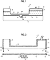
FIG. 1 is an illustration showing a diagrammatic side view of an embodiment of a system for automated permeation of a biological material in accordance with certain aspects of the present disclosure. -
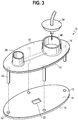
FIG. 2 is an illustration showing a diagrammatic cut-away view of the embodiment of the system ofFIG. 1 in accordance with certain aspects of the present disclosure. -
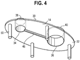
FIG. 3 is an illustration showing a diagrammatic perspective view of another embodiment of a system for automated permeation of a biological material in accordance with certain aspects of the present disclosure. -
FIG. 4 is an illustration showing a diagrammatic perspective view of an upper portion of the embodiment of the system ofFIG. 3 in accordance with certain aspects of the present disclosure. -
FIG. 5 is an illustration showing a diagrammatic cut-away view of a lower portion of another embodiment of a system for automated permeation of a biological material in accordance with certain aspects of the present disclosure. -
FIG. 6 is an illustration showing a diagrammatic perspective view of a lower portion of another embodiment of a system for automated permeation of a biological material in accordance with certain aspects of the present disclosure. -
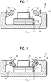
FIG. 7 is an illustration showing a diagrammatic side view of an embodiment of a kit for automated permeation of a biological material, in accordance with certain aspects of the present disclosure, including a closing device in its open position. -
FIG. 8 is an illustration showing another diagrammatic side view of the embodiment of the kit ofFIG. 7 , in accordance with certain aspects of the present disclosure, including the closing device in its closed position. -
FIG. 9 is an illustration showing the changing process of the concentration of liquids in a biological material during permeation processes in accordance with certain aspects of the present disclosure. - Various aspects are described below with reference to the drawings in which like elements generally are identified by like numerals. The relationship and functioning of the various elements of the aspects may better be understood by reference to the following detailed description. However, aspects are not limited to those illustrated in the drawings or explicitly described below. It also should be understood that the drawings are not necessarily to scale (although certain drawings may be drawn to scale and relied upon as such), and in certain instances details may have been omitted that are not necessary for an understanding of aspects disclosed herein, such as conventional material, construction, and assembly.
- For purposes of promoting an understanding of the presently disclosed embodiments, reference will now be made to the embodiments illustrated in the drawings, and specific language will be used to describe the same. It should nevertheless be understood that no limitation of the scope of the invention is thereby intended, such alterations and further modifications in the illustrated device, and such further applications of the principles of the invention as illustrated therein being contemplated as would normally occur to one skilled in the art to which the invention relates. The term "configured to" is used to describe structural limitations in a particular manner that requires specific construction to accomplish a stated function and/or to interface or interact with another component(s), and is not used to describe mere intended or theoretical uses. Relative terminology and broader terms such as "generally," "about," "substantially," and the like will be understood by those of skill in the art as providing clear and definite scope of disclosure and/or claiming. For example, the term "generally square" will be understood as not requiring exactly square, but rather including that and functional equivalents.
- Referring to
FIGS. 1-8 , embodiments of asystem 10 for automated permeation of a biological material are shown. Thesystem 10 may include alower portion 12 and anupper portion 14 configured to be releasably coupled to thelower portion 12. Thelower portion 12 may include atop surface 16, abottom surface 18, and agroove 20 extending from thetop surface 16 towards thebottom surface 18. Thegroove 20 may be configured to receivingly support a biological material 22 (e.g., as shown inFIGS. 1-2 ). Thebiological material 22 may be various kinds of biological materials, such as an embryo or an oocyte. Thegroove 20 may be configured to accommodate the various kinds of biological materials, such that thebiological material 22 may be placed therein to be permeated with desired liquids, as discussed in greater detail below. - The configuration of the
groove 20 may be varied, as desired and/or needed, without departing from the scope of the present invention. For example, in some embodiments, as shown inFIG. 5 , thegroove 20 may include afirst section 24 and asecond section 26, where thefirst section 24 may extend from thetop surface 16 of thelower portion 12 to anintermediate surface 28 of thelower portion 12 and thesecond section 26 may extend from theintermediate surface 28 of thelower portion 12 towards thebottom surface 18 of thelower portion 12. This embodiment increases the depth of thegroove 20 and creates another channel over thebiological material 22, which may be advantageous for slowing down the permeation rate of a solution into thebiological material 22, as discussed in greater detail below. - In some embodiments, when the
system 10 is used to prepare thebiological material 22 for vitrification (e.g., cryopreservation of thebiological material 22 by permeating thebiological material 22 with cryoprotectant solutions), a vitrification stick, as shown inFIG. 6 , may be used as thelower portion 12 of thesystem 10, which may allow the user to permeate thebiological material 22 directly on the vitrification stick, such that when the permeation process is completed, the vitrification stick supporting thebiological material 22 may be directly placed into a vitrification solution, such as liquid nitrogen, for vitrification of thebiological material 22 without additional transfer of thebiological material 22. - Referring to
FIGS. 1-4 , theupper portion 14 may include anupper surface 30 and alower surface 32, where thelower surface 32 may include afirst opening 34 and asecond opening 36. Theupper portion 14 may also include afirst protrusion 38 extending outwardly from theupper surface 30 of theupper portion 14 and in fluid communication with thefirst opening 34 and asecond protrusion 40 extending outwardly from theupper surface 30 of theupper portion 14 and in fluid communication with thesecond opening 36. As shown inFIGS. 1-2 , thelower portion 12 and theupper portion 14 are configured such that when they are coupled together (e.g., placing theupper portion 14 upon the lower portion 12), thefirst protrusion 38 and thetop surface 16 of thelower portion 12 may collectively form afirst reservoir 42 and thesecond protrusion 40 and thetop surface 16 of thelower portion 12 may collectively form asecond reservoir 44. - In some embodiments, as shown in
FIG. 1 , thefirst reservoir 42, thesecond reservoir 44, and thegroove 20 may be in fluid communication with each other, and the first andsecond reservoirs upper portions 12 and 14) via the first andsecond reservoirs groove 20 may be disposed between the first andsecond reservoirs groove 20 through thefirst reservoir 42 or thesecond reservoir 44, as discussed in greater detail below. - In some embodiments, as shown in
FIG. 4 , thelower surface 32 of theupper portion 14 may include aslot 46 disposed between and in fluid communication with the first andsecond openings slot 46 may extend from thelower surface 32 of theupper portion 14 towards theupper surface 30 of theupper portion 14. In some embodiments, theslot 46 may be configured such that when theupper portion 14 is coupled to (e.g., placed upon) thelower portion 12, theslot 46 and thetop surface 16 of thelower portion 12 may collectively form achannel 48, as shown inFIG. 1 , where thechannel 48 is in fluid communication with thegroove 20 and the first andsecond reservoirs FIG. 1 , thegroove 20 may be disposed in registry with thechannel 48. - In some embodiments, the lower and
upper portions upper portion 14 is coupled to (e.g., placed upon) thelower portion 12, thetop surface 16 of thelower portion 12 sealingly engages thelower surface 32 of theupper portion 14, thereby sealing thechannel 48, such that liquids introduced into thesystem 10, through one of the first andsecond reservoirs channel 48 and past thegroove 20, as discussed in greater detail below. In some embodiments, the lower andupper portions FIG. 2 by diagrammatic connection means 47a/47b/47c/47d, which can include any connection-enhancers referenced herein, alone or in combination with each other (including, without limit, one or more of magnets, clips, flexible seals, adhesive material/structure, and hinges) (e.g., only one clip may be needed when the lower andupper portions upper portions upper portion 14 may have a non-toxic rubber or silicone liner configured to facilitate sealing thechannel 48. In some embodiments, as shown inFIGS. 3 and4 , theupper portion 14 may include at least one leg 50 (e.g., a plurality of legs; when theupper portion 14 and thelower portion 12 are hinged together, only oneleg 50 may be needed) extending outwardly from thelower surface 32 of theupper portion 14, thelower portion 12 may include at least one aperture 52 (e.g., a plurality of apertures) configured for receiving the at least one leg 50 (e.g., a plurality of apertures are configured for receiving a plurality of legs, respectively) when theupper portion 14 is coupled to thelower portion 12. This embodiment is advantageous for facilitating aligning the lower andupper portions 12 and 14 (e.g., when the lower andupper portions channel 48. - When the
system 10 is used for permeating abiological material 22, thebiological material 22 may be placed in the groove before theupper portion 14 is coupled to (e.g., placed upon) thelower portion 12. After thesystem 10 is closed (e.g., theupper portion 14 is disposed upon thelower portion 12 and sealingly engages the lower portion 12), liquids may be introduced into thesystem 10 through one of the first andsecond reservoirs 42 and 44 (e.g., liquids are introduced into the first reservoir 42). The other reservoir (e.g., the reservoir that was not used for introducing liquids into thesystem 10; the second reservoir 44) may be configured to be coupled to a suction device such that suction applied to the other reservoir (e.g., the second reservoir 44) may cause the liquids to flow along/in thechannel 48 and into thegroove 20, and may further cause the liquids to flow past thegroove 20, along/in thechannel 48, and towards/into the other reservoir (e.g., the second reservoir 44). In some embodiments, additionally or alternatively, the reservoir that was used for introducing liquids into the system 10 (e.g., the first reservoir 42) may be configured to be coupled to a positive pressure device such that positive pressure applied to the reservoir that was used for introducing liquids into the system 10 (e.g., the first reservoir 42) may cause the liquids to flow along/in thechannel 48 and into thegroove 20, and may further cause the liquids to flow past thegroove 20, along/in thechannel 48, and towards/into the other reservoir (e.g., the second reservoir 44). - As one example, in some embodiments, as shown in
FIGS. 1-3 , thefirst reservoir 42 may be configured to allow liquids to be introduced into the system through thefirst reservoir 42. Thefirst reservoir 42 may be configured to be coupled to a positive pressure device and/or thesecond reservoir 44 may be configured to be coupled to a suction device such that positive pressure applied to thefirst reservoir 42 and/or suction applied to thesecond reservoir 44 may cause liquids introduced into thesystem 10 through thefirst reservoir 42 to flow along thechannel 48, and into thegroove 20, and may further cause the liquids to flow past thegroove 20, along thechannel 48, and into thesecond reservoir 44, such that thebiological material 22 disposed in thegroove 20 may be permeated with the liquids passing through thebiological material 22, as discussed in greater detail below. In this embodiment, thesecond reservoir 44 may also be used as a petri dish in the event that thebiological material 22 flows out of thegroove 20 and into thesecond reservoir 44. In some embodiments, as shown inFIG. 3 , thesystem 10 may also include alid 54 configured to be removably coupled to thesecond reservoir 44, such that a user may remove thelid 54 and get access to thesecond reservoir 44 to retrieve thebiological material 22 that flows into thesecond reservoir 44, when needed. It will be appreciated that thesystem 10 would be configured (e.g., by controlling a predetermined suction (and/or positive pressure) force and rate) to prevent thebiological material 22 from washing away, but theremovable lid 54 is a precautionary design feature. - In some embodiments, another system may be provided to facilitate sealingly closing the system 10 (e.g., sealingly coupling the
upper portion 14 and the lower portion 12). As one example, in some embodiments, as shown inFIGS. 7-8 , akit 56 for automated permeation of a biological material is shown. Thekit 56 may include thesystem 10 and adevice 58, where thedevice 58 may be configured for receivingly support thesystem 10. Thedevice 58 may include acavity 60 and at least one arm for closing the system 10 (e.g., only one arm may be needed when the lower andupper portions system 10 is placed in thecavity 60 and the at least one arm is in the closed position, the at least one arm may engage anupper surface 30 of theupper portion 14 of thesystem 10, such that thesystem 10 is secured within thecavity 60 with theupper portion 14 of thesystem 10 sealingly engaging thelower portion 12 of thesystem 10. - In some embodiments, as shown in
FIGS. 7-8 , thedevice 58 includes twoarms arms FIG. 7 ), theupper portion 14 of thesystem 10 may be free to be placed onto and removed from thelower portion 12 of thesystem 10. When the twoarms FIG. 8 ), thesystem 10 may be secured within thecavity 60 with theupper portion 14 of thesystem 10 sealingly engaging thelower portion 12 of thesystem 10. In some embodiments, as shown inFIGS. 7-8 , the twoarms FIG. 7 ) and the closed position (e.g., as shown inFIG. 8 ), and when the twoarms FIG. 8 ), the twoarms upper surface 30 of theupper portion 14 of thesystem 10 placed in thecavity 60 of thedevice 58. In some embodiments, thedevice 58 may be part of an equipment that provides suction to thesecond reservoir 44 of thesystem 10 and/or provides positive pressure to thefirst reservoir 42 of thesystem 10. - In some embodiments, the
system 10 may be manufactured out of clear plastic that do not react to the liquids to be used with thesystem 10 for permeation of the biological material 22 (e.g., cryoprotectant agents in the vitrification solution, discussed below). Potential materials may include acrylics, polycarbonate, cyclic olefin copolymers, or styrene-butadiene-methacrylic co-polymers. Using clear plastic materials is advantageous for allowing a user to monitor thebiological material 22 during the permeation process. In some embodiments, thesystem 10 may be manufactured of an opaque or translucent material optionally with a clear window (generically represented inFIG. 1 bydiagrammatic windows biological material 22 disposed in thesystem 10 for visualization. In some embodiments, thesystem 10 may include a total length 72 (e.g., as shown inFIG. 1 ) between about 3 cm and about 10 cm, with the first andsecond reservoirs FIGS. 3 and4 , where the first andsecond reservoirs system 10, e.g., the first reservoir 42) may be configured for a volume between about 0.5 ml and about 5 ml. The waste reservoir (the reservoir not used for introducing liquids into thesystem 10, e.g., the second reservoir 44) may have the capacity to hold up to three times the volume of the loading reservoir (e.g., the first reservoir 42). The width 74 (e.g., as shown inFIGS. 7 and 8 ) of thesystem 10 may be between about 2 cm to about 5 cm. Thechannel 48 may have a generally square cross-section between about 0.5 mm and about 5 mm wide. Thegroove 20 for thebiological material 22 may range from about 0.5x0.5x0.5 mm to about 3x3x3 mm. The term "about" is specifically defined herein to include the specific value referenced as well as a dimension that is within 5% of the dimension both above and below the dimension. - A method of permeating a
biological material 22 using thesystem 10 will be described below. A user may place abiological material 22 in thegroove 20 of thelower portion 12 of thesystem 10. Then the user may couple theupper portion 14 of thesystem 10 to thelower portion 12 of the system 10 (e.g., by placing theupper portion 14 upon the lower portion 12). Then the user may place a first liquid into thefirst reservoir 42 and apply a first suction to the second reservoir 44 (and/or apply a first positive pressure to the first reservoir 42) such that the first liquid flows along thechannel 48 into thegroove 20 and permeate thebiological material 22, and may further flow past thegroove 20 towards thesecond reservoir 44. It will be appreciated by varying the suction (and/or positive pressure) force, rate and/or duration, the permeation process (e.g., rate, degree, and duration of the permeation) will be varied as desired and/or needed. That is, the user may apply the first suction (and/or the first positive pressure) at a predetermined force, rate, and duration such that thebiological material 22 is permeated with the first liquid in a predetermined manner. It will be appreciated that one or more liquids (e.g., a second liquid) may be sequentially introduced into thesystem 10 and one or more suctions (e.g., a second suction) may be correspondingly applied to the second reservoir 44 (and/or one or more positive pressures (e.g., a second positive pressure) may be correspondingly applied to the first reservoir 42), such that the one or more liquids may sequentially flow along thechannel 48 into thegroove 20, and thebiological material 22 may be permeated with the one or more liquids, as desired and/or needed. It will be appreciated that the permeation process may be automated by presetting the type and order of the one or more liquids to be introduced into thesystem 10, the suctions to be applied to thesecond reservoir 44, and/or positive pressures to be applied to the first reservoir 42 (e.g., presetting the force, rate, and duration of each suction (and/or positive pressure), and the time interval between the suctions (and/or positive pressures) if more than one suction (and/or positive pressure) is applied). - In some embodiments, the
system 10 may be used with cryoprotectant solutions for cryopreservation of a biological material such that the biological material is ready for vitrification. While asystem 10 for permeation of an embryo for cryopreservation of the embryo is specifically described below, thesystem 10 may be successfully implemented for use with other types of liquids and/or other types of biological materials (e.g., oocytes or another cell type) for other medical and/or experimental uses. For the sake of brevity, a system disclosed below is described and depicted as a system for cryopreservation of an embryo, one of ordinary skill in the art, with a thorough review of the subject specification and figures, would readily comprehend how the system may be implemented for automated permeation of other types of biological materials with the same or other types of liquids for the same or other medical and/or experimental uses, and would comprehend which other types of biological materials, liquids, and uses might be suitable without undue experimentation. - When the
system 10 is used for cryopreservation of anembryo 22, thesystem 10 may be provided with cryoprotectant solutions with different concentrations. In some embodiments, increasing concentration of cryoprotectant solutions may be sequentially introduced into thesystem 10 via thefirst reservoir 42, and corresponding suctions may be applied to the second reservoir 44 (and/or corresponding positive pressures may be applied to the first reservoir 42), such that theembryo 22 disposed in thegroove 20 may be permeated with increasing cryoprotectant concentrations in a desired manner, and such that when the permeation process is completed, theembryo 22 is ready for vitrification. For the sake of brevity, the method of using thesystem 10 for cryopreservation of theembryo 22 using three liquids will be described below. A person of ordinary skill in the art will understand how to use thesystem 10 for cryopreservation of theembryo 22 with a greater/smaller number of liquids. - For example, after the
system 10 is closed with theembryo 22 disposed in thegroove 20, a first liquid with a first cryoprotectant concentration may be introduced into thesystem 10 via thefirst reservoir 42. Then a first suction may be applied to the second reservoir 44 (and/or a first positive pressure may be applied to the first reservoir 42), which causes the first liquid to flow along thechannel 48 into thegroove 20 and permeate theembryo 22. After allowing theembryo 22 to be permeated with the first liquid for a first predetermined time, a second liquid with a second cryoprotectant concentration, greater than the first cryoprotectant concentration, may be introduced into thesystem 10 via thefirst reservoir 42. Then a second suction may be applied to the second reservoir 44 (and/or a second positive pressure may be applied to the first reservoir 42), which causes the second liquid to flow along thechannel 48 into thegroove 20. The force, rate, and duration of the second suction (and/or the second positive pressure) may be preset and may determine how gradually the second liquid mixes with the first liquid in thegroove 20 and forms a first mixed liquid with a first mixed cryoprotectant concentration, and how gradually theembryo 22 is permeated with the first mixed liquid. - After allowing the
embryo 22 to be permeated with the first mixed liquid for a second predetermined time, a third liquid with a third cryoprotectant concentration, greater than the second cryoprotectant concentration, may be introduced into thesystem 10 via thefirst reservoir 42. Then a third suction may be applied to the second reservoir 44 (and/or a third positive pressure may be applied to the first reservoir 42), which causes the third liquid to flow along thechannel 48 into thegroove 20. The force, rate, and duration of the third suction (and/or the third positive pressure) may be preset and may determine how gradually the third liquid mixes with the first mixed liquid in thegroove 20 and forms a second mixed liquid with a second mixed cryoprotectant concentration, and how gradually theembryo 22 is permeated with the second mixed liquid. After allowing theembryo 22 to be permeated with the second mixed liquid for a third predetermined time, the permeation process may be completed and thesystem 10 may automatically stop working. The first, second, and third predetermined times may be selected and preset such that when the permeation process is completed, theembryo 22 is ready for vitrification. After the permeation process is completed, a user may open thesystem 10 and extract theembryo 22 from thegroove 20 of thelower portion 12 of thesystem 10 and place theembryo 22 in a device for vitrification. - It will be appreciated that applying suction to the second reservoir 44 (and/or applying positive pressure to the first reservoir 42) to cause the liquids to flow past the
embryo 22 is advantageous for allowing the cryoprotectant concentrations in thegroove 20 to increase gradually and allowing theembryo 22 to be permeated with the increasing cryoprotectant concentrations gradually, thereby providing an improved control of the permeation rate. The increasing pattern of the cryoprotectant concentrations in thegroove 20 may be varied, as desired and/or needed, by varying the configuration of the system 10 (e.g., the volume of thefirst reservoir 42, the length, width, and height of thechannel 48, the length, width, and depth of thegroove 20, and the distance between thefirst reservoir 42 and the groove 20) and/or the suction (and/or positive pressure) force, rate, and duration, such that desired and/or needed mixing rates of the first, second, and third liquids may be achieved. The increasing pattern of the cryoprotectant concentrations in thegroove 20 may determine how gradually theembryo 22 experiences and uptakes the changes in cryoprotectant concentration. - In some embodiments, the
system 10 may be configured and the first, second, and third suctions (and/or the first, second, and third positive pressures) may be designed, such that the achieved greatest cryoprotectant concentrations of the first liquid, the first mixed liquid, and the second mixed liquid may be 0%, 17%, and 55% by volume, respectively. As shown inFIG. 9 , unlike conventional devices that expose theembryo 22 to increasing concentrations in steps (e.g., as shown as thecurve 66, where theembryo 22 experiences two fast increases in cryoprotectant concentration), thesystem 10 may allow theembryo 22 to be exposed gradually to the final cryoprotectant concentration (e.g., as shown as thecurve 68, when the user places a fully-concentrated vitrification solution on the loading reservoir (e.g., the first reservoir 42), or as shown as thecurve 70, when the user adds increasing concentrations to slow down the permeation process even further). - While various embodiments of the present disclosure have been described, the present disclosure is not to be restricted except in light of the attached claims and their equivalents.
- In an aspect there is provided a system for permeation of a biological material, comprising: a lower portion; and an upper portion configured to be releasably coupled to the lower portion, wherein the lower portion includes a groove for holding a biological material, wherein the lower portion and the upper portion are operable to be coupled such that a first reservoir and a second reservoir are formed collectively by the lower portion and the upper portion, and wherein the first reservoir, the second reservoir, and the groove are in fluid communication with each other.
- The groove may be disposed between the first reservoir and the second reservoir.
- The system may be made of a clear plastic, or an opaque or translucent material optionally with a clear window above and/or below a location where, in use, a biological material is to be disposed in the system for visualization.
- The lower portion and the upper portion may be connected by a hinge, a mechanical clip, magnets, flexible seals, or any combination thereof.
- The second reservoir may be configured to be coupled to a suction device and/or the first reservoir is configured to be coupled to a positive pressure device.
- The lower portion and the upper portion may be configured such that a liquid placed in the first reservoir can flow past the groove towards the second reservoir in response to suction applied to the second reservoir and/or through a positive pressure applied to the first reservoir.
- The lower portion may include a top surface and a bottom surface, and wherein the groove extends from the top surface of the lower portion towards the bottom surface of the lower portion.
- The groove may include a first section and a second section, and wherein the first section extends from the top surface of the lower portion to an intermediate surface of the lower portion and the second section extends from the intermediate surface of the lower portion towards the bottom surface of the lower portion.
- The upper portion may include an upper surface and a lower surface, wherein the lower surface of the upper portion includes a first opening, a second opening, and a slot disposed between and in fluid communication with the first and second openings, and wherein the slot extends from the lower surface of the upper portion towards the upper surface of the upper portion.
- The upper portion may be coupled to the lower portion, the slot and the top surface of the lower portion collectively form a channel in fluid communication with the first and second reservoirs, and the groove is in registry with the channel.
- The upper portion and/or the lower portion may be arranged so that the upper portion is operable to couple to the lower portion, such that the top surface of the lower portion sealingly engages the lower surface of the upper portion such that a liquid introduced into the first reservoir flows, in the channel, towards the second reservoir when a suction is applied to the second reservoir and/or when a positive pressure is applied to the first reservoir. It will be appreciated in the context of the present disclosure that these and other pressures referred to herein may comprise relative pressures - e.g. defined relative to a common reference pressure such as ambient pressure.
- The upper portion may include a first protrusion extending outwardly from the upper surface of the upper portion and in fluid communication with the first opening. The upper portion may also include a second protrusion extending outwardly from the upper surface of the upper portion and in fluid communication with the second opening.
- The system (e.g. the upper portion and/or the lower portion) may be arranged so that when the upper portion is coupled to the lower portion, the first protrusion and the top surface of the lower portion collectively form the first reservoir, and the second protrusion and the top surface of the lower portion collectively form the second reservoir.
- The upper portion may include at least one leg extending outwardly from the lower surface of the upper portion, and wherein the lower portion includes at least one aperture configured for receiving the at least one leg when the upper portion is coupled to the lower portion.
- The system may be further configured to be receivingly supported by a device, wherein the device includes a cavity and at least one arm movable between an open position and a closed position, and wherein when the system is placed in the cavity and the at least one arm is in the closed position, the system is secured within the cavity with the upper portion of the system sealingly engaging the lower portion of the system.
- One skilled in the relevant art will recognize that numerous variations and modifications may be made to the embodiments described above without departing from the scope of the present invention, as defined by the appended claims. Moreover, the advantages described herein are not necessarily the only advantages of the present disclosure and it is not necessarily expected that every embodiment of the present disclosure will achieve all of the advantages described.
Claims (15)
- A system for permeation of a biological material, comprising:a lower portion; andan upper portion configured to be releasably coupled to the lower portion,wherein the lower portion includes a groove configured to receivingly support a biological material,wherein the lower portion and the upper portion are coupled such that a first reservoir and a second reservoir are formed collectively by the lower portion and the upper portion, andwherein the first reservoir, the second reservoir, and the groove are in fluid communication with each other.
- The system of claim 1, wherein the groove is disposed between the first reservoir and the second reservoir.
- The system of claim 1 or 2,wherein the system is made of clear plastic, orwherein the system is made of an opaque or translucent material optionally with a clear window above and/or below a biological material disposed in the system for visualization.
- The system of any preceding claim, wherein the lower portion and the upper portion are connected by a hinge, a mechanical clip, magnets, flexible seals, or any combination thereof.
- The system of any preceding claim, wherein the second reservoir is configured to be coupled to a suction device and/or the first reservoir is configured to be coupled to a positive pressure device.
- The system of any preceding claim, wherein the lower portion and the upper portion are configured such that a liquid placed in the first reservoir can flow past the groove towards the second reservoir through a suction applied to the second reservoir and/or through a positive pressure applied to the first reservoir.
- The system of any preceding claim, wherein the lower portion includes a top surface and a bottom surface, and wherein the groove extends from the top surface of the lower portion towards the bottom surface of the lower portion.
- The system of any preceding claim, wherein the groove includes a first section and a second section, and wherein the first section extends from the top surface of the lower portion to an intermediate surface of the lower portion and the second section extends from the intermediate surface of the lower portion towards the bottom surface of the lower portion.
- The system of any preceding claim, wherein the upper portion includes an upper surface and a lower surface, wherein the lower surface of the upper portion includes a first opening, a second opening, and a slot disposed between and in fluid communication with the first and second openings, and wherein the slot extends from the lower surface of the upper portion towards the upper surface of the upper portion.
- The system of any preceding claim, wherein when the upper portion is coupled to the lower portion, the slot and the top surface of the lower portion collectively form a channel in fluid communication with the first and second reservoirs, and the groove is in registry with the channel.
- The system of any preceding claim, wherein when the upper portion is coupled to the lower portion, the top surface of the lower portion sealingly engages the lower surface of the upper portion such that a liquid introduced into the first reservoir flows, in the channel, towards the second reservoir when a suction is applied to the second reservoir and/or when a positive pressure is applied to the first reservoir.
- The system of any preceding claim, wherein the upper portion includes a first protrusion extending outwardly from the upper surface of the upper portion and in fluid communication with the first opening, and wherein the upper portion includes a second protrusion extending outwardly from the upper surface of the upper portion and in fluid communication with the second opening.
- The system of any preceding claim, wherein when the upper portion is coupled to the lower portion, the first protrusion and the top surface of the lower portion collectively form the first reservoir, and the second protrusion and the top surface of the lower portion collectively form the second reservoir.
- The system of any preceding claim, wherein the upper portion includes at least one leg extending outwardly from the lower surface of the upper portion, and wherein the lower portion includes at least one aperture configured for receiving the at least one leg when the upper portion is coupled to the lower portion.
- The system of any preceding claim, wherein the system is further configured to be receivingly supported by a device, wherein the device includes a cavity and at least one arm movable between an open position and a closed position, and wherein when the system is placed in the cavity and the at least one arm is in the closed position, the system is secured within the cavity with the upper portion of the system sealingly engaging the lower portion of the system.
Applications Claiming Priority (1)
| Application Number | Priority Date | Filing Date | Title |
|---|---|---|---|
| US202062977597P | 2020-02-17 | 2020-02-17 |
Publications (1)
| Publication Number | Publication Date |
|---|---|
| EP3878556A1 true EP3878556A1 (en) | 2021-09-15 |
Family
ID=74666649
Family Applications (1)
| Application Number | Title | Priority Date | Filing Date |
|---|---|---|---|
| EP21157723.4A Pending EP3878556A1 (en) | 2020-02-17 | 2021-02-17 | System for automated permeation of a biological material and method of using same |
Country Status (2)
| Country | Link |
|---|---|
| US (1) | US11856947B2 (en) |
| EP (1) | EP3878556A1 (en) |
Citations (4)
| Publication number | Priority date | Publication date | Assignee | Title |
|---|---|---|---|---|
| US20070264705A1 (en) * | 2003-09-10 | 2007-11-15 | John Dodgson | Apparatus and Method for Handling Cells, Embryos or Oocytes |
| US20130204076A1 (en) * | 2010-06-25 | 2013-08-08 | Tsinghua University | Integrated microfluidic device for single oocyte trapping |
| US20130230912A1 (en) * | 2010-09-30 | 2013-09-05 | The University Of Tokyo | Base body and method for manufacturing base body |
| US20150093815A1 (en) * | 2013-09-30 | 2015-04-02 | Gnubio, Inc. | Microfluidic cartridge devices and methods of use and assembly |
Family Cites Families (32)
| Publication number | Priority date | Publication date | Assignee | Title |
|---|---|---|---|---|
| US5723282A (en) | 1991-07-08 | 1998-03-03 | The American National Red Cross | Method of preparing organs for vitrification |
| US5728351A (en) | 1993-01-21 | 1998-03-17 | Cdc Technologies, Inc. | Apparatus for making a plurality of reagent mixtures and analyzing particle distributions of the reagent mixtures |
| US5823954A (en) | 1994-09-22 | 1998-10-20 | Chaffringeon; Bernard | Single-use device for detecting or analyzing a body fluid |
| CA2320296A1 (en) | 1998-05-18 | 1999-11-25 | University Of Washington | Liquid analysis cartridge |
| AU2707100A (en) | 1998-11-30 | 2000-06-19 | Ivf Sciences Colorado, Inc. | System and sequential culture media for in vitro fertilization |
| GB0115103D0 (en) | 2001-06-20 | 2001-08-15 | Abed Farhang | Apparatus for and methods of preparing sperm |
| US7223371B2 (en) | 2002-03-14 | 2007-05-29 | Micronics, Inc. | Microfluidic channel network device |
| EP1654066B1 (en) | 2003-07-31 | 2014-11-12 | Handylab, Inc. | Processing particle-containing samples |
| US7682009B1 (en) | 2004-06-01 | 2010-03-23 | Sliwa Jr John W | Cooling, condensation and freezing of atmospheric water or of a microfluidic working-material in or on microfluidic devices |
| US8143070B2 (en) | 2007-06-05 | 2012-03-27 | Ecolab Usa Inc. | Optical cell |
| CN101835886A (en) | 2007-08-24 | 2010-09-15 | 智能生物系统有限公司 | Mesoscale bioreactor platform for perfusion |
| EP2214828A1 (en) | 2007-11-07 | 2010-08-11 | Bellbrook Labs, Llc | Microfluidic device having stable static gradient for analyzing chemotaxis |
| EP2224800B1 (en) | 2007-11-20 | 2013-01-09 | Max-Planck-Gesellschaft zur Förderung der Wissenschaften e.V. | Ultra-rapid freezing device and method |
| US7943293B2 (en) | 2008-05-28 | 2011-05-17 | Genx International, Inc. | Media solutions and methods for cryopreservation and thawing of in vitro fertilization specimens |
| US7976789B2 (en) | 2008-07-22 | 2011-07-12 | The Board Of Trustees Of The University Of Illinois | Microfluidic device for preparing mixtures |
| EP2156735A1 (en) | 2008-08-13 | 2010-02-24 | Dr. H. Zech GmbH | Method and instrument for vitrification and storing of biological specimen |
| AU2009285530A1 (en) | 2008-08-29 | 2010-03-04 | The Curators Of The University Of Missouri | High-throughput and non-invasive method to vitrify porcine embryos |
| US20110250690A1 (en) | 2008-11-11 | 2011-10-13 | Craig H Randall | Microfluidic Embryo and Gamete Culture Systems |
| GB2479112B (en) | 2009-02-24 | 2013-05-01 | Schlumberger Holdings | Micro-valve and micro-fluidic device using such |
| US9169460B2 (en) | 2009-05-19 | 2015-10-27 | Lifeglobal Group Llc | Flooding dish and method for changing media in the dish in the preparation of mammalian specimen culture and for cryo-preservation, freezing, vitrification and the thawing and warming of such specimens |
| DE102009023430B4 (en) | 2009-05-29 | 2013-07-25 | Siemens Aktiengesellschaft | Apparatus and method for controlling fluid flows in lab-on-a-chip systems and method of manufacturing the apparatus |
| AU2010258716B2 (en) | 2009-06-12 | 2015-11-12 | Revvity Health Sciences, Inc. | Compositions and methods for dehydrated storage of on-board reagents in microfluidic devices |
| AU2011257909B2 (en) | 2010-05-28 | 2015-06-18 | Genea Ip Holdings Pty Limited | Improved micromanipulation and storage apparatus and methods |
| JP2012118039A (en) * | 2010-11-12 | 2012-06-21 | Sony Corp | Microchip |
| US20120251999A1 (en) | 2011-02-01 | 2012-10-04 | The Brigham And Women's Hospital, Inc. | Vitrification systems and methods |
| WO2013020032A2 (en) | 2011-08-04 | 2013-02-07 | University Of Kansas | Automated vitrification device |
| GB2509440B (en) * | 2011-10-25 | 2015-06-03 | Ibm | Microfluidic device with interconnects |
| US20150313211A1 (en) | 2012-12-05 | 2015-11-05 | Neobios Pte. Ltd. | A Method of Vitrification |
| US9597685B2 (en) * | 2013-01-31 | 2017-03-21 | Luminex Corporation | Fluid retention plates and analysis cartridges |
| WO2015057641A1 (en) | 2013-10-15 | 2015-04-23 | The Regents Of The University Of Michigan | Vitrification of biological material |
| WO2016001933A1 (en) | 2014-07-03 | 2016-01-07 | Fertilesafe Ltd | Device for preparing a biological sample for vitrification, and a method for utilizing it |
| EP3990181A1 (en) | 2019-06-27 | 2022-05-04 | Cook Medical Technologies LLC | System for passive permeation of a biological material and method of using same |
-
2021
- 2021-02-12 US US17/174,638 patent/US11856947B2/en active Active
- 2021-02-17 EP EP21157723.4A patent/EP3878556A1/en active Pending
Patent Citations (4)
| Publication number | Priority date | Publication date | Assignee | Title |
|---|---|---|---|---|
| US20070264705A1 (en) * | 2003-09-10 | 2007-11-15 | John Dodgson | Apparatus and Method for Handling Cells, Embryos or Oocytes |
| US20130204076A1 (en) * | 2010-06-25 | 2013-08-08 | Tsinghua University | Integrated microfluidic device for single oocyte trapping |
| US20130230912A1 (en) * | 2010-09-30 | 2013-09-05 | The University Of Tokyo | Base body and method for manufacturing base body |
| US20150093815A1 (en) * | 2013-09-30 | 2015-04-02 | Gnubio, Inc. | Microfluidic cartridge devices and methods of use and assembly |
Also Published As
| Publication number | Publication date |
|---|---|
| US11856947B2 (en) | 2024-01-02 |
| US20210251216A1 (en) | 2021-08-19 |
Similar Documents
| Publication | Publication Date | Title |
|---|---|---|
| JP7208210B2 (en) | Ultramicroscopic sample management device for biological fluids | |
| US8282896B2 (en) | Devices and methods for holding microfluidic devices | |
| US20140302552A1 (en) | Multi-Chambered Tissue Containment System for Molecular and Histology Diagnostics | |
| JP6533223B2 (en) | System and method for cell culture device interconnects and fluidic device interconnects | |
| EP2532424B1 (en) | Fluid displacement tissue container for molecular and histology diagnostics | |
| US20190126266A1 (en) | Pinch to open sample collection device | |
| US20190381499A1 (en) | Blood metering device with desiccant and support for storage media and inlay with flange | |
| ES3060038T3 (en) | Filtration assembly and method for microbiological testing | |
| US10634590B2 (en) | IHC, tissue slide fluid exchange disposable and system | |
| US9186670B2 (en) | Functionalized microfluidic device and method | |
| ES3060060T3 (en) | Filtration assembly and method for microbiological testing | |
| US20020142470A1 (en) | Directional acceleration vector-driven displacement of fluids (DAVD-DOF) | |
| WO2001014065A1 (en) | Holder for specimen examination | |
| US11856947B2 (en) | System for automated permeation of a biological material and method of using same | |
| US6531061B1 (en) | Disposable dialysis cassette | |
| JPH0867B2 (en) | Inoculator and assembly | |
| JPWO2020003504A1 (en) | Perfusion culture system | |
| EP0669855A1 (en) | DEVICE FOR COLLECTING AND PROCESSING BIOLOGICAL SAMPLES. | |
| Mansouri et al. | Transforming static barrier tissue models into dynamic microphysiological systems | |
| JP2021522888A (en) | Biofluid microsample management device | |
| JP2022044563A (en) | Test equipment, press-fitting method and microchannel device | |
| WO2020263891A1 (en) | System for passive permeation of a biological material and method of using same | |
| NL2034141B1 (en) | Improvements to biopsy devices | |
| JP2014098595A (en) | Sample liquid injection tool and sample liquid heat treatment apparatus | |
| WO2021259497A1 (en) | Microfluidic chip and pumping device |
Legal Events
| Date | Code | Title | Description |
|---|---|---|---|
| PUAI | Public reference made under article 153(3) epc to a published international application that has entered the european phase |
Free format text: ORIGINAL CODE: 0009012 |
|
| STAA | Information on the status of an ep patent application or granted ep patent |
Free format text: STATUS: THE APPLICATION HAS BEEN PUBLISHED |
|
| AK | Designated contracting states |
Kind code of ref document: A1 Designated state(s): AL AT BE BG CH CY CZ DE DK EE ES FI FR GB GR HR HU IE IS IT LI LT LU LV MC MK MT NL NO PL PT RO RS SE SI SK SM TR |
|
| STAA | Information on the status of an ep patent application or granted ep patent |
Free format text: STATUS: REQUEST FOR EXAMINATION WAS MADE |
|
| 17P | Request for examination filed |
Effective date: 20220119 |
|
| RBV | Designated contracting states (corrected) |
Designated state(s): AL AT BE BG CH CY CZ DE DK EE ES FI FR GB GR HR HU IE IS IT LI LT LU LV MC MK MT NL NO PL PT RO RS SE SI SK SM TR |
|
| STAA | Information on the status of an ep patent application or granted ep patent |
Free format text: STATUS: EXAMINATION IS IN PROGRESS |
|
| 17Q | First examination report despatched |
Effective date: 20230426 |
|
| RAP1 | Party data changed (applicant data changed or rights of an application transferred) |
Owner name: NEW US OPCO INC. |
|
| RAP3 | Party data changed (applicant data changed or rights of an application transferred) |
Owner name: NEXPRING US OPCO INC. |