EP3878262A1 - Agricultural apparatus - Google Patents
Agricultural apparatus Download PDFInfo
- Publication number
- EP3878262A1 EP3878262A1 EP21160896.3A EP21160896A EP3878262A1 EP 3878262 A1 EP3878262 A1 EP 3878262A1 EP 21160896 A EP21160896 A EP 21160896A EP 3878262 A1 EP3878262 A1 EP 3878262A1
- Authority
- EP
- European Patent Office
- Prior art keywords
- height
- control unit
- work units
- crop
- agricultural vehicle
- Prior art date
- Legal status (The legal status is an assumption and is not a legal conclusion. Google has not performed a legal analysis and makes no representation as to the accuracy of the status listed.)
- Withdrawn
Links
Images


Classifications
-
- A—HUMAN NECESSITIES
- A01—AGRICULTURE; FORESTRY; ANIMAL HUSBANDRY; HUNTING; TRAPPING; FISHING
- A01D—HARVESTING; MOWING
- A01D34/00—Mowers; Mowing apparatus of harvesters
- A01D34/006—Control or measuring arrangements
-
- A—HUMAN NECESSITIES
- A01—AGRICULTURE; FORESTRY; ANIMAL HUSBANDRY; HUNTING; TRAPPING; FISHING
- A01D—HARVESTING; MOWING
- A01D34/00—Mowers; Mowing apparatus of harvesters
- A01D34/006—Control or measuring arrangements
- A01D34/008—Control or measuring arrangements for automated or remotely controlled operation
-
- A—HUMAN NECESSITIES
- A01—AGRICULTURE; FORESTRY; ANIMAL HUSBANDRY; HUNTING; TRAPPING; FISHING
- A01D—HARVESTING; MOWING
- A01D34/00—Mowers; Mowing apparatus of harvesters
- A01D34/01—Mowers; Mowing apparatus of harvesters characterised by features relating to the type of cutting apparatus
- A01D34/412—Mowers; Mowing apparatus of harvesters characterised by features relating to the type of cutting apparatus having rotating cutters
- A01D34/42—Mowers; Mowing apparatus of harvesters characterised by features relating to the type of cutting apparatus having rotating cutters having cutters rotating about a horizontal axis, e.g. cutting-cylinders
- A01D34/54—Cutting-height adjustment
-
- A—HUMAN NECESSITIES
- A01—AGRICULTURE; FORESTRY; ANIMAL HUSBANDRY; HUNTING; TRAPPING; FISHING
- A01D—HARVESTING; MOWING
- A01D34/00—Mowers; Mowing apparatus of harvesters
- A01D34/01—Mowers; Mowing apparatus of harvesters characterised by features relating to the type of cutting apparatus
- A01D34/412—Mowers; Mowing apparatus of harvesters characterised by features relating to the type of cutting apparatus having rotating cutters
- A01D34/63—Mowers; Mowing apparatus of harvesters characterised by features relating to the type of cutting apparatus having rotating cutters having cutters rotating about a vertical axis
- A01D34/74—Cutting-height adjustment
-
- A—HUMAN NECESSITIES
- A01—AGRICULTURE; FORESTRY; ANIMAL HUSBANDRY; HUNTING; TRAPPING; FISHING
- A01D—HARVESTING; MOWING
- A01D57/00—Delivering mechanisms for harvesters or mowers
- A01D57/20—Delivering mechanisms for harvesters or mowers with conveyor belts
-
- A—HUMAN NECESSITIES
- A01—AGRICULTURE; FORESTRY; ANIMAL HUSBANDRY; HUNTING; TRAPPING; FISHING
- A01D—HARVESTING; MOWING
- A01D75/00—Accessories for harvesters or mowers
- A01D75/30—Arrangements for trailing two or more mowers
- A01D75/303—Arrangements for trailing two or more mowers for mowers positioned one behind the other or side by side
Definitions
- the present invention relates to an agricultural apparatus comprising an agricultural vehicle and a number of work units suitable for generating swathes of cut crop, and in particular to a mowing apparatus for cutting a standing crop such as hay.
- a mower combination in which a first mower unit is located ahead of an agricultural vehicle such as a tractor with two further mower units trailing the agricultural vehicle.
- the rear mower units may be provided with conveyors for depositing cut crop into a swath or swathes behind the agricultural vehicle.
- When turning the mower units are raised from a working position to a raised headland position.
- the intent is that the mower units are raised above the swath or swathes such that the mower units do not disturb the cut crop as the mower units are moved over the swath or swathes.
- the swath or swathes of cut crop produced may be so high that overrunning of the swath or swathes with the mower units in the headland position is no longer possible without causing damage to the swath or swathes of cut crop.
- an agricultural apparatus comprises an agricultural vehicle together with a front work unit and two lateral work units located behind and to the sides of the front work unit, the front work unit having a connection to a front of the agricultural vehicle and the lateral work units sharing a connection to a rear of the agricultural vehicle, each of the work units depositing a cut crop as a swath, one or more sensors for determining a height of one or more of the deposited swaths, a control unit for controlling a height of the connections above a ground surface, characterised in that if the height of one or more of the deposited swaths is determined to exceed a predetermined value, the control unit causes the height of the rear connection to be raised.
- the agricultural apparatus includes a further sensor to detect the presence of crop ahead of the front work unit and in the event of no crop being detected as present the control unit causes one or more of the work units to move from the working position to the headland position.
- a method of operation of a mower combination comprises the steps of providing a predetermined set of values to the control unit, monitoring the height of the one or more deposited swaths by providing signals representative of the height of the one or more deposited swaths, the control unit comparing the signals representing the height of the one or more deposited swaths against a predetermined set of values and as required signalling at least the rear connection to be displaced based on this comparison.
- the method comprises the additional step of monitoring for the presence of standing crop ahead of the agricultural vehicle, and in the event of no crop being detected as present the control unit causing one or more of the work units to move from the working position to the headland position.
- a computer implemented method comprises the steps of a control unit receiving a plurality of signals, the signals representing the height of at least a first swath deposited by the work units the control unit being configured to receive the plurality of signals and compare the signals for the height of at least the first swath deposited by the work units against a predetermined set of values and as required generate a signal to cause the position of the rear connection to be adjusted based on the comparison.
- the method comprises the additional step of monitoring for the presence of standing crop ahead of the agricultural vehicle, and in the event of no crop being detected as present the control unit causing one or more of the work units to move from the working position to the headland position.
- a computer readable program comprises instructions that causes one or more processors to implement the method of the third aspect of the invention.
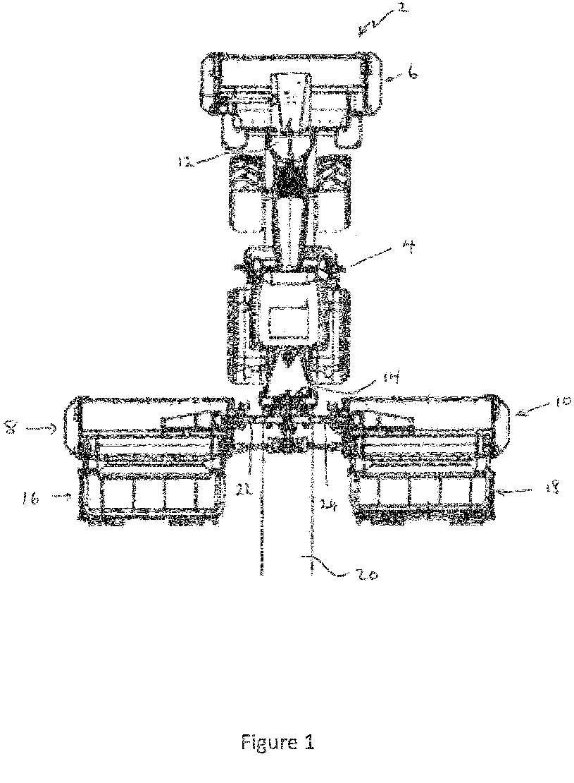
- FIG. 1 a plan view of an agricultural apparatus 2 for use in the present invention is shown.
- An agricultural apparatus 2 comprises an agricultural vehicle 4 such as a tractor and a number of work units 6,8,10 suitable for cutting standing crop, the work units 6,8,10 being connected to the agricultural vehicle.
- the work units include a front work unit 6 located to the front of the agricultural vehicle 4 and two lateral work units 8,10 located behind and to the sides of the front work unit 6, each of the work units 6,8,10 depositing cut crop as a swath.
- the front work unit 6 is conveniently mounted on a front hitch 12 of the agricultural vehicle 4.
- the work units comprise mowing units.
- the lateral mowing units 8,10 are supported from a central chassis by lifting units, for example hydraulic units 22,24.
- Each hydraulic unit 22,24 may be used to move a respective lateral mowing unit 8,10 between a working position and a transport position.
- a headland position may be defined between the working position and the transport position.
- the height of each of the lateral mowing units 8,10 above a ground surface 21 may be further controlled by operation of the hydraulic units 22,24 between minimum and maximum displacement values, that is across a ground adaptation range.
- FIG 1 a swath 20 produced by the front work unit 6 is shown.
- conveyors 16,18 mounted to the rear of the lateral work units 8,10 will direct cut crop inwardly to produce a broader central swath. These swathes are omitted from Figure 1 for clarity.
- a sensor 26 ( Figure 2 ) is provided to determine a displacement or position 50 of the rear hitch 14, that is the relative position of the rear hitch assembly in relation to a reference position on the agricultural vehicle ( Figures 3 to 7 ).
- An operator can control operation of the front and rear work units 6,8,10 from within the agricultural vehicle 4 by use of a suitable user terminal 30.
- the operator can cause each of the work units to move about the central frame a working position to a headland position, can cause each of the lateral work units 8,10 to move between the working position and the transport position.
- the operator can also control the working height of the lateral mowing units 8,10 within the ground adaptation range by use of the hydraulic units 22,24.
- the user terminal 30 communicates with an electronic control unit 32.
- the control unit 32 provides signals to control operation of the front and rear hitches 12,14 of the agricultural vehicle 4 and provides signals to control operation of the mowing units 6,8,10 and the conveyor units 16,18.
- the signals are provided by way of a suitable data communication network 40 such as one compliant with the ISOBUS standard (a network in conformance to ISO 11783).
- the control unit 32 may conveniently comprise a single processor located on the agricultural vehicle or its functions may be split between a processor located on the agricultural vehicle and one or more additional processors located on the mowing units 6,8,10, the additional processor(s) being in electronic communication with the first processor.
- the control unit 32 is also able to access a suitable memory 34.
- the memory 34 may take any suitable form and is in electronic communication with the control unit 32.
- a sensor 28 is provided for providing a signal representative of a height 27 of the deposited swath 20.
- the sensor 28 may be located on the front work unit 6 or on the agricultural vehicle 4 as is convenient.
- the sensor 28 is in electronic communication with the control unit 24.
- the sensor 28 has particular use for determining the height of the deposited swath 20 where the operator is about to execute a headland operation with the agricultural apparatus 2.
- the swath 20 of cut crop produced may be so high that overrunning of the swath 20 in the headland position is no longer possible without causing damage to the swath 20 since the raised height 35 of the lateral work units 8,10 is less than the height 27 of the swath 20.
- the height 27 of the swath is detected (step 100) and a signal sent to the control unit 24.
- the control unit 24 compares this value to a predetermined value (step 102).
- the predetermined value is conveniently stored in the memory 34 in any suitable manner such as a database or look up table.
- the predetermined value corresponds to the normal operating height of the lateral work unit 8,10 when in a headland position. If the value of the height of the swath is less than the predetermined value the control unit 24 takes no further action (step 104).
- control unit 24 causes the rear hitch 14 of the agricultural vehicle to be raised (step 106) thereby raising the lateral work units 8,10 such that the lateral work units 8,10 can no longer damage the swath 20 of cut crop.
- a front sensor 42 is provided to detect the presence or absence of standing crop ahead of the agricultural apparatus 2.
- This front sensor 42 may be mounted on the agricultural vehicle 4 or the front work unit 6. Alternatively an aggregated signal from sensors 42 on both the agricultural vehicle 4 and the front work unit 6 may be used.
- the control unit 24 detects the signal from the front sensor 42 (step 300 Figure 6 ) and determines the presence or absence of standing crop head of the front work unit 6 (step 302).
- control unit 24 takes no action and the work units 6,8,10 continue to operate in the working position (step 304). If no standing crop is detected the control unit 24 causes the work units 6,8,10 to move to the headland positions (step 306). In this way the when the edge of the standing crop to be processed is reached, the agricultural implement is operated to reach the headland position as soon as possible.
- the front work unit 6 may first be moved to a headland position and the lateral work units 8,10 may be subsequently controlled to continue cutting the standing crop until the edge of the standing crop is reached and then the lateral work units 8,10 also are automatically raised to their headland position.
Landscapes
- Life Sciences & Earth Sciences (AREA)
- Environmental Sciences (AREA)
- Harvester Elements (AREA)
- Agricultural Machines (AREA)
- Guiding Agricultural Machines (AREA)
Abstract
Description
- The present invention relates to an agricultural apparatus comprising an agricultural vehicle and a number of work units suitable for generating swathes of cut crop, and in particular to a mowing apparatus for cutting a standing crop such as hay.
- It is known to provide a mower combination in which a first mower unit is located ahead of an agricultural vehicle such as a tractor with two further mower units trailing the agricultural vehicle. The rear mower units may be provided with conveyors for depositing cut crop into a swath or swathes behind the agricultural vehicle. When turning the mower units are raised from a working position to a raised headland position. The intent is that the mower units are raised above the swath or swathes such that the mower units do not disturb the cut crop as the mower units are moved over the swath or swathes. However, in certain case, due to the high mass yields of the cut crop, the swath or swathes of cut crop produced may be so high that overrunning of the swath or swathes with the mower units in the headland position is no longer possible without causing damage to the swath or swathes of cut crop.
- It is an advantage of the present invention that it avoids damage to the swath or swathes of cut crop with the mower units in the headland position in such cases.
- Other advantages of the present invention will become apparent as discussed below.
- According to a first aspect of the present invention, an agricultural apparatus comprises an agricultural vehicle together with a front work unit and two lateral work units located behind and to the sides of the front work unit, the front work unit having a connection to a front of the agricultural vehicle and the lateral work units sharing a connection to a rear of the agricultural vehicle, each of the work units depositing a cut crop as a swath, one or more sensors for determining a height of one or more of the deposited swaths, a control unit for controlling a height of the connections above a ground surface, characterised in that if the height of one or more of the deposited swaths is determined to exceed a predetermined value, the control unit causes the height of the rear connection to be raised.
- Preferably the agricultural apparatus includes a further sensor to detect the presence of crop ahead of the front work unit and in the event of no crop being detected as present the control unit causes one or more of the work units to move from the working position to the headland position.
- According to a second aspect of the invention, a method of operation of a mower combination according to the first aspect of the invention comprises the steps of providing a predetermined set of values to the control unit, monitoring the height of the one or more deposited swaths by providing signals representative of the height of the one or more deposited swaths, the control unit comparing the signals representing the height of the one or more deposited swaths against a predetermined set of values and as required signalling at least the rear connection to be displaced based on this comparison.
- Preferably the method comprises the additional step of monitoring for the presence of standing crop ahead of the agricultural vehicle, and in the event of no crop being detected as present the control unit causing one or more of the work units to move from the working position to the headland position.
- According to a third aspect of the invention, a computer implemented method comprises the steps of a control unit receiving a plurality of signals, the signals representing the height of at least a first swath deposited by the work units the control unit being configured to receive the plurality of signals and compare the signals for the height of at least the first swath deposited by the work units against a predetermined set of values and as required generate a signal to cause the position of the rear connection to be adjusted based on the comparison.
- Preferably the method comprises the additional step of monitoring for the presence of standing crop ahead of the agricultural vehicle, and in the event of no crop being detected as present the control unit causing one or more of the work units to move from the working position to the headland position.
- According to a fourth aspect of the invention, a computer readable program comprises instructions that causes one or more processors to implement the method of the third aspect of the invention.
- The invention will now be described, by way of example only, with reference to the accompanying drawings, in which:
-
Figure 1 shows a plan view of an agricultural apparatus for use in the present invention; -
Figure 2 shows a schematic view of elements of an agricultural apparatus for use in the present invention; -
Figure 3 shows a schematic side view of a portion of an agricultural apparatus provided with lateral work units illustrating a problem with known configurations; -
Figure 4 shows a schematic side view of a portion of an agricultural apparatus provided with lateral work units in accordance with the present invention; -
Figure 5 shows a flow diagram in relation to a first operation of the agricultural apparatus in accordance with the present invention; and -
Figure 6 shows a flow diagram in relation to a further operation of the agricultural apparatus in accordance with the present invention. - The invention will now be described in the following detailed description with reference to the drawings, wherein preferred embodiments are described in detail to enable practice of the invention. Although the invention is described with reference to these specific preferred embodiments, it will be understood that the invention is not limited to these preferred embodiments. But to the contrary, the invention includes numerous alternatives, modifications and equivalents as will become apparent from consideration of the following detailed description.
- Reference to terms such as longitudinal, transverse and vertical are made with respect to a longitudinal vehicle axis which is parallel to a normal forward direction of travel.
- With reference to
Figure 1 , a plan view of an agricultural apparatus 2 for use in the present invention is shown. - An agricultural apparatus 2 comprises an agricultural vehicle 4 such as a tractor and a number of
work units work units front work unit 6 located to the front of the agricultural vehicle 4 and twolateral work units front work unit 6, each of thework units front work unit 6 is conveniently mounted on afront hitch 12 of the agricultural vehicle 4. In a preferred embodiment the work units comprise mowing units. - The
lateral mowing units hydraulic units hydraulic unit lateral mowing unit lateral mowing units ground surface 21 may be further controlled by operation of thehydraulic units - In
Figure 1 , aswath 20 produced by thefront work unit 6 is shown. InFigure 1 conveyors lateral work units Figure 1 for clarity. - A sensor 26 (
Figure 2 ) is provided to determine a displacement orposition 50 of therear hitch 14, that is the relative position of the rear hitch assembly in relation to a reference position on the agricultural vehicle (Figures 3 to 7 ). - An operator can control operation of the front and
rear work units suitable user terminal 30. For example the operator can cause each of the work units to move about the central frame a working position to a headland position, can cause each of thelateral work units lateral mowing units hydraulic units - The
user terminal 30 communicates with anelectronic control unit 32. Thecontrol unit 32 provides signals to control operation of the front andrear hitches mowing units conveyor units data communication network 40 such as one compliant with the ISOBUS standard (a network in conformance to ISO 11783). - The
control unit 32 may conveniently comprise a single processor located on the agricultural vehicle or its functions may be split between a processor located on the agricultural vehicle and one or more additional processors located on themowing units - The
control unit 32 is also able to access asuitable memory 34. Thememory 34 may take any suitable form and is in electronic communication with thecontrol unit 32. - A
sensor 28 is provided for providing a signal representative of aheight 27 of the depositedswath 20. Thesensor 28 may be located on thefront work unit 6 or on the agricultural vehicle 4 as is convenient. Thesensor 28 is in electronic communication with thecontrol unit 24. Thesensor 28 has particular use for determining the height of the depositedswath 20 where the operator is about to execute a headland operation with the agricultural apparatus 2. - By reference to
Figure 3 a known problem with the state of the art is illustrated. At high mass yields of a standing crop, theswath 20 of cut crop produced may be so high that overrunning of theswath 20 in the headland position is no longer possible without causing damage to theswath 20 since the raisedheight 35 of thelateral work units height 27 of theswath 20. - In addressing this this problem reference is made to
Figures 4 and5 . Theheight 27 of the swath is detected (step 100) and a signal sent to thecontrol unit 24. Thecontrol unit 24 compares this value to a predetermined value (step 102). The predetermined value is conveniently stored in thememory 34 in any suitable manner such as a database or look up table. The predetermined value corresponds to the normal operating height of thelateral work unit control unit 24 takes no further action (step 104). If the value of the height of the swath is equal to or greater than the predetermined value thecontrol unit 24 causes therear hitch 14 of the agricultural vehicle to be raised (step 106) thereby raising thelateral work units lateral work units swath 20 of cut crop. - In a further embodiment, a
front sensor 42 is provided to detect the presence or absence of standing crop ahead of the agricultural apparatus 2. Thisfront sensor 42 may be mounted on the agricultural vehicle 4 or thefront work unit 6. Alternatively an aggregated signal fromsensors 42 on both the agricultural vehicle 4 and thefront work unit 6 may be used. Thecontrol unit 24 detects the signal from the front sensor 42 (step 300Figure 6 ) and determines the presence or absence of standing crop head of the front work unit 6 (step 302). - If standing crop is detected, the
control unit 24 takes no action and thework units control unit 24 causes thework units - By monitoring the speed of the agricultural vehicle 4 the
front work unit 6 may first be moved to a headland position and thelateral work units lateral work units - From reading the present disclosure, other modifications will be apparent to persons skilled in the art. Such modifications may involve other features which are already known in the field of mowers and component parts therefore and which may be used instead of or in addition to features already described herein.
Claims (7)
- An agricultural apparatus comprising an agricultural vehicle together with a front work unit and two lateral work units located behind and to the sides of the front work unit, the front work unit having a connection to a front of the agricultural vehicle and the lateral work units sharing a connection to a rear of the agricultural vehicle, each of the work units depositing a cut crop as a swath, one or more sensors for determining a height of one or more of the deposited swaths, a control unit for controlling a height of the connections above a ground surface, characterised in that if the height of one or more of the deposited swaths is determined to exceed a predetermined value, the control unit causes the height of the rear connection to be raised.
- An agricultural apparatus according to claim 1, characterised in that the agricultural apparatus includes a further sensor to detect the presence of crop ahead of the front work unit and in the event of no crop being detected as present the control unit causes one or more of the work units to move from the working position to the headland position.
- A method of operation of a mower combination according to claim 1, is characterised in that it comprises the steps of providing a predetermined set of values to the control unit, monitoring the height of the one or more deposited swaths by providing signals representative of the height of the one or more deposited swaths, the control unit comparing the signals representing the height of the one or more deposited swaths against a predetermined set of values and as required signalling at least the rear connection to be displaced based on this comparison.
- A method according to claim 3, characterised in that the method comprises the additional step of monitoring for the presence of standing crop ahead of the agricultural vehicle, and in the event of no crop being detected as present the control unit causing one or more of the work units to move from the working position to the headland position.
- A computer implemented method comprises the steps of a control unit receiving a plurality of signals, the signals representing the height of at least a first swath deposited by the work units the control unit being configured to receive the plurality of signals and compare the signals for the height of at least the first swath deposited by the work units against a predetermined set of values and as required generate a signal to cause the position of the rear connection to be adjusted based on the comparison.
- A computer implemented method according to claim 5, characterised in that the method comprises the additional step of monitoring for the presence of standing crop ahead of the agricultural vehicle, and in the event of no crop being detected as present the control unit causing one or more of the work units to move from the working position to the headland position.
- A computer readable program comprising instructions that causes one or more processors to implement the method of claim 5 or claim 6.
Applications Claiming Priority (1)
| Application Number | Priority Date | Filing Date | Title |
|---|---|---|---|
| GBGB2003486.4A GB202003486D0 (en) | 2020-03-11 | 2020-03-11 | Agricultural apparatus |
Publications (1)
| Publication Number | Publication Date |
|---|---|
| EP3878262A1 true EP3878262A1 (en) | 2021-09-15 |
Family
ID=70453557
Family Applications (1)
| Application Number | Title | Priority Date | Filing Date |
|---|---|---|---|
| EP21160896.3A Withdrawn EP3878262A1 (en) | 2020-03-11 | 2021-03-05 | Agricultural apparatus |
Country Status (3)
| Country | Link |
|---|---|
| US (1) | US20210282317A1 (en) |
| EP (1) | EP3878262A1 (en) |
| GB (1) | GB202003486D0 (en) |
Families Citing this family (4)
| Publication number | Priority date | Publication date | Assignee | Title |
|---|---|---|---|---|
| US12178154B2 (en) | 2021-01-20 | 2024-12-31 | Venture Products, Inc. | Method and apparatus for mounting a flail mower |
| US12290023B2 (en) * | 2021-01-20 | 2025-05-06 | Venture Products, Inc. | Method and apparatus for mounting a flail mower |
| US12250901B2 (en) * | 2021-01-20 | 2025-03-18 | Venture Products, Inc. | Method and apparatus for mounting a flail mower |
| US12256667B2 (en) * | 2021-01-20 | 2025-03-25 | Venture Products, Inc. | Method and apparatus for mounting a flail mower |
Citations (4)
| Publication number | Priority date | Publication date | Assignee | Title |
|---|---|---|---|---|
| US20040149461A1 (en) * | 2002-10-10 | 2004-08-05 | Daniel Ocsenknecht | Device for controlling the position of a mountable implement relative to an implement carrier element |
| EP1813142A1 (en) * | 2006-01-31 | 2007-08-01 | Alois Pöttinger Maschinenfabrik GmbH | Agricultural machine |
| US20170311541A1 (en) * | 2016-05-02 | 2017-11-02 | Cnh Industrial America Llc | Programmable one-touch raise feature for an agricultural harvester such as a windrower |
| US20190116717A1 (en) * | 2016-06-03 | 2019-04-25 | Kverneland Group Kerteminde As | Method and device for operating an agricultural machine |
Family Cites Families (12)
| Publication number | Priority date | Publication date | Assignee | Title |
|---|---|---|---|---|
| US3177638A (en) * | 1960-09-30 | 1965-04-13 | Arthur L Johnson | Wide swath mower convertible for highway travel |
| NL6716443A (en) * | 1967-12-04 | 1969-06-06 | ||
| US3731469A (en) * | 1972-01-24 | 1973-05-08 | Jacobsen Mfg Co | Convertible gang lawn mower |
| US5069022A (en) * | 1990-09-28 | 1991-12-03 | Befco, Inc. | Gang mower apparatus |
| DE19959484A1 (en) * | 1999-12-10 | 2001-06-13 | Deere & Co | Mower |
| FR2837347B1 (en) * | 2002-03-21 | 2004-07-30 | Kuhn Sa | AGRICULTURAL MOWER COMPRISING A CARRIER VEHICLE AND SEVERAL WORKING UNITS |
| US7869922B2 (en) * | 2004-04-12 | 2011-01-11 | Cnh America Llc | Method and apparatus to put a windrower header in the transport mode under specified conditions |
| US8688331B2 (en) * | 2009-12-18 | 2014-04-01 | Agco Corporation | Method to enhance performance of sensor-based implement height control |
| DE102012004045A1 (en) * | 2011-05-03 | 2012-12-06 | Claas Saulgau Gmbh | "Harvesting machine with at least one cross conveyor" |
| US9585309B2 (en) * | 2015-07-14 | 2017-03-07 | Cnh Industrial America Llc | Header height control system for an agricultural harvester |
| DE102015118767A1 (en) * | 2015-11-03 | 2017-05-04 | Claas Selbstfahrende Erntemaschinen Gmbh | Environment detection device for agricultural machine |
| US10806078B2 (en) * | 2017-05-12 | 2020-10-20 | Deere & Company | Control system for adjusting conditioning rollers of work vehicle |
-
2020
- 2020-03-11 GB GBGB2003486.4A patent/GB202003486D0/en not_active Ceased
-
2021
- 2021-03-05 EP EP21160896.3A patent/EP3878262A1/en not_active Withdrawn
- 2021-03-11 US US17/199,264 patent/US20210282317A1/en not_active Abandoned
Patent Citations (4)
| Publication number | Priority date | Publication date | Assignee | Title |
|---|---|---|---|---|
| US20040149461A1 (en) * | 2002-10-10 | 2004-08-05 | Daniel Ocsenknecht | Device for controlling the position of a mountable implement relative to an implement carrier element |
| EP1813142A1 (en) * | 2006-01-31 | 2007-08-01 | Alois Pöttinger Maschinenfabrik GmbH | Agricultural machine |
| US20170311541A1 (en) * | 2016-05-02 | 2017-11-02 | Cnh Industrial America Llc | Programmable one-touch raise feature for an agricultural harvester such as a windrower |
| US20190116717A1 (en) * | 2016-06-03 | 2019-04-25 | Kverneland Group Kerteminde As | Method and device for operating an agricultural machine |
Also Published As
| Publication number | Publication date |
|---|---|
| GB202003486D0 (en) | 2020-04-29 |
| US20210282317A1 (en) | 2021-09-16 |
Similar Documents
| Publication | Publication Date | Title |
|---|---|---|
| US20210282317A1 (en) | Agricultural apparatus comprising height sensors, and related methods | |
| CN110352697B (en) | System for controlling operating parameters of a harvesting header and agricultural harvester | |
| US9326443B2 (en) | Arrangement and method for the automatic transfer of crops from a harvesting machine to a transport vehicle | |
| CN110582198B (en) | Harvester | |
| WO2014093814A1 (en) | Predictive load estimation through forward vision | |
| US20190116717A1 (en) | Method and device for operating an agricultural machine | |
| EP3878267B1 (en) | Mower combination | |
| JP2019004772A (en) | Harvesting machine | |
| EP3837952B1 (en) | Mower combination | |
| EP3837954B1 (en) | Mower combination | |
| JP7670285B2 (en) | Harvesting Machine | |
| EP3837953B1 (en) | Agricultural apparatus | |
| US11778949B2 (en) | Mower combination with location based conveyor control | |
| EP3878263B1 (en) | Mower combination | |
| EP3878264B1 (en) | Agricultural apparatus | |
| US20240074356A1 (en) | Method and control device for operating an agricultural harvester and agricultural harvester | |
| US12317773B2 (en) | Self-propelled agricultural harvester machine and header assembly control system | |
| US20220192087A1 (en) | Agricultural apparatus | |
| JP2022002479A (en) | Harvester | |
| EP3837956B1 (en) | Mower combination | |
| US20260007099A1 (en) | Agricultural header adjustment for reducing material stagnation | |
| JP2955439B2 (en) | Cutting height control device of reaper and harvester | |
| JPH06319337A (en) | Reaping height controller for reaping harvester |
Legal Events
| Date | Code | Title | Description |
|---|---|---|---|
| PUAI | Public reference made under article 153(3) epc to a published international application that has entered the european phase |
Free format text: ORIGINAL CODE: 0009012 |
|
| STAA | Information on the status of an ep patent application or granted ep patent |
Free format text: STATUS: THE APPLICATION HAS BEEN PUBLISHED |
|
| AK | Designated contracting states |
Kind code of ref document: A1 Designated state(s): AL AT BE BG CH CY CZ DE DK EE ES FI FR GB GR HR HU IE IS IT LI LT LU LV MC MK MT NL NO PL PT RO RS SE SI SK SM TR |
|
| STAA | Information on the status of an ep patent application or granted ep patent |
Free format text: STATUS: REQUEST FOR EXAMINATION WAS MADE |
|
| 17P | Request for examination filed |
Effective date: 20220315 |
|
| RBV | Designated contracting states (corrected) |
Designated state(s): AL AT BE BG CH CY CZ DE DK EE ES FI FR GB GR HR HU IE IS IT LI LT LU LV MC MK MT NL NO PL PT RO RS SE SI SK SM TR |
|
| STAA | Information on the status of an ep patent application or granted ep patent |
Free format text: STATUS: THE APPLICATION IS DEEMED TO BE WITHDRAWN |
|
| 18D | Application deemed to be withdrawn |
Effective date: 20220316 |
|
| P01 | Opt-out of the competence of the unified patent court (upc) registered |
Effective date: 20230518 |