EP3878165B1 - Electronic device including rotatable camera - Google Patents
Electronic device including rotatable camera Download PDFInfo
- Publication number
- EP3878165B1 EP3878165B1 EP20788629.2A EP20788629A EP3878165B1 EP 3878165 B1 EP3878165 B1 EP 3878165B1 EP 20788629 A EP20788629 A EP 20788629A EP 3878165 B1 EP3878165 B1 EP 3878165B1
- Authority
- EP
- European Patent Office
- Prior art keywords
- electronic device
- state
- rack gear
- camera module
- module unit
- Prior art date
- Legal status (The legal status is an assumption and is not a legal conclusion. Google has not performed a legal analysis and makes no representation as to the accuracy of the status listed.)
- Active
Links
Images





Classifications
-
- H—ELECTRICITY
- H04—ELECTRIC COMMUNICATION TECHNIQUE
- H04M—TELEPHONIC COMMUNICATION
- H04M1/00—Substation equipment, e.g. for use by subscribers
- H04M1/02—Constructional features of telephone sets
- H04M1/0202—Portable telephone sets, e.g. cordless phones, mobile phones or bar type handsets
- H04M1/026—Details of the structure or mounting of specific components
- H04M1/0264—Details of the structure or mounting of specific components for a camera module assembly
-
- G—PHYSICS
- G06—COMPUTING OR CALCULATING; COUNTING
- G06F—ELECTRIC DIGITAL DATA PROCESSING
- G06F1/00—Details not covered by groups G06F3/00 - G06F13/00 and G06F21/00
- G06F1/16—Constructional details or arrangements
- G06F1/1601—Constructional details related to the housing of computer displays, e.g. of CRT monitors, of flat displays
- G06F1/1605—Multimedia displays, e.g. with integrated or attached speakers, cameras, microphones
-
- G—PHYSICS
- G06—COMPUTING OR CALCULATING; COUNTING
- G06F—ELECTRIC DIGITAL DATA PROCESSING
- G06F1/00—Details not covered by groups G06F3/00 - G06F13/00 and G06F21/00
- G06F1/16—Constructional details or arrangements
- G06F1/1613—Constructional details or arrangements for portable computers
- G06F1/1633—Constructional details or arrangements of portable computers not specific to the type of enclosures covered by groups G06F1/1615 - G06F1/1626
- G06F1/1656—Details related to functional adaptations of the enclosure, e.g. to provide protection against EMI, shock, water, or to host detachable peripherals like a mouse or removable expansions units like PCMCIA cards, or to provide access to internal components for maintenance or to removable storage supports like CDs or DVDs, or to mechanically mount accessories
- G06F1/1658—Details related to functional adaptations of the enclosure, e.g. to provide protection against EMI, shock, water, or to host detachable peripherals like a mouse or removable expansions units like PCMCIA cards, or to provide access to internal components for maintenance or to removable storage supports like CDs or DVDs, or to mechanically mount accessories related to the mounting of internal components, e.g. disc drive or any other functional module
-
- G—PHYSICS
- G06—COMPUTING OR CALCULATING; COUNTING
- G06F—ELECTRIC DIGITAL DATA PROCESSING
- G06F1/00—Details not covered by groups G06F3/00 - G06F13/00 and G06F21/00
- G06F1/16—Constructional details or arrangements
- G06F1/1613—Constructional details or arrangements for portable computers
- G06F1/1633—Constructional details or arrangements of portable computers not specific to the type of enclosures covered by groups G06F1/1615 - G06F1/1626
- G06F1/1684—Constructional details or arrangements related to integrated I/O peripherals not covered by groups G06F1/1635 - G06F1/1675
- G06F1/1686—Constructional details or arrangements related to integrated I/O peripherals not covered by groups G06F1/1635 - G06F1/1675 the I/O peripheral being an integrated camera
-
- H—ELECTRICITY
- H04—ELECTRIC COMMUNICATION TECHNIQUE
- H04M—TELEPHONIC COMMUNICATION
- H04M1/00—Substation equipment, e.g. for use by subscribers
- H04M1/02—Constructional features of telephone sets
- H04M1/0202—Portable telephone sets, e.g. cordless phones, mobile phones or bar type handsets
- H04M1/0206—Portable telephones comprising a plurality of mechanically joined movable body parts, e.g. hinged housings
- H04M1/0208—Portable telephones comprising a plurality of mechanically joined movable body parts, e.g. hinged housings characterized by the relative motions of the body parts
- H04M1/0235—Slidable or telescopic telephones, i.e. with a relative translation movement of the body parts; Telephones using a combination of translation and other relative motions of the body parts
- H04M1/0237—Sliding mechanism with one degree of freedom
-
- H—ELECTRICITY
- H04—ELECTRIC COMMUNICATION TECHNIQUE
- H04N—PICTORIAL COMMUNICATION, e.g. TELEVISION
- H04N23/00—Cameras or camera modules comprising electronic image sensors; Control thereof
- H04N23/50—Constructional details
-
- H—ELECTRICITY
- H04—ELECTRIC COMMUNICATION TECHNIQUE
- H04N—PICTORIAL COMMUNICATION, e.g. TELEVISION
- H04N23/00—Cameras or camera modules comprising electronic image sensors; Control thereof
- H04N23/57—Mechanical or electrical details of cameras or camera modules specially adapted for being embedded in other devices
-
- H—ELECTRICITY
- H04—ELECTRIC COMMUNICATION TECHNIQUE
- H04M—TELEPHONIC COMMUNICATION
- H04M2250/00—Details of telephonic subscriber devices
- H04M2250/20—Details of telephonic subscriber devices including a rotatable camera
-
- H—ELECTRICITY
- H04—ELECTRIC COMMUNICATION TECHNIQUE
- H04N—PICTORIAL COMMUNICATION, e.g. TELEVISION
- H04N23/00—Cameras or camera modules comprising electronic image sensors; Control thereof
- H04N23/50—Constructional details
- H04N23/51—Housings
Definitions
- the present disclosure relates generally to an electronic device, and more particularly to an electronic device including a rotatable camera.
- EP 3651 446 A1 discusses an electronic device which includes a pop-up and rotational camera.
- US 2007/013555 A1 discusses a mobile communication terminal that includes a terminal body and a camera assembly mounted in the terminal body.
- US 2005/049019 A1 discusses a sliding-type mobile communication terminal having a camera module interlocking with a sliding motion.
- an electronic device may maximize the display of the electronic device.
- the locking hook and the locking guide limit a movement of the slide portion by a physical locking structure, and in a process of switching to the front camera and the rear camera, even when an unexpected external force is applied, the slide portion may be fixed and the module unit may rotate without interfering with a peripheral structure.
- FIG. 1 illustrates an electronic device in a network environment according to an embodiment.
- an electronic device 101 in a network environment 100 may communicate with an electronic device 102 via a first network 198 (e.g., a short-range wireless communication network), or an electronic device 104 or a server 108 via a second network 199 (e.g., a long-range wireless communication network).
- the electronic device 101 may communicate with the electronic device 104 via the server 108.
- the electronic device 101 includes a processor 120, memory 130, an input device 150, an audio output device 155, a display device 160, an audio module 170, a sensor module 176, an interface 177, a haptic module 179, a camera module 180, a power management module 188, a battery 189, a communication module 190, a subscriber identification module (SIM) 196, and an antenna module 197.
- a processor 120 memory 130, an input device 150, an audio output device 155, a display device 160, an audio module 170, a sensor module 176, an interface 177, a haptic module 179, a camera module 180, a power management module 188, a battery 189, a communication module 190, a subscriber identification module (SIM) 196, and an antenna module 197.
- SIM subscriber identification module
- At least one of the components may be omitted from the electronic device 101, or one or more other components may be added in the electronic device 101.
- Some of the components may
- the processor 120 may execute a program 140 to control at least one other hardware or software component of the electronic device 101 coupled with the processor 120, and may perform various data processing or computation. As at least part of the data processing or computation, the processor 120 may load a command or data received from another component in volatile memory 132, process the command or the data stored in the volatile memory 132, and store resulting data in non-volatile memory 134.
- the processor 120 may include a main processor 121 (e.g., a central processing unit (CPU) or an application processor (AP)), and an auxiliary processor 123 (e.g., a graphics processing unit (GPU), an image signal processor (ISP), a sensor hub processor, or a communication processor (CP)) that is operable independently from, or in conjunction with, the main processor 121. Additionally or alternatively, the auxiliary processor 123 may be adapted to consume less power than the main processor 121, or to be specific to a specified function. The auxiliary processor 123 may be implemented as separate from, or as part of the main processor 121.
- a main processor 121 e.g., a central processing unit (CPU) or an application processor (AP)
- auxiliary processor 123 e.g., a graphics processing unit (GPU), an image signal processor (ISP), a sensor hub processor, or a communication processor (CP)
- the auxiliary processor 123 may be adapted to consume less power than the main processor 121, or
- the auxiliary processor 123 may control at least some of functions or states related to at least one component among the components of the electronic device 101, instead of the main processor 121 while the main processor 121 is in an inactive (e.g., sleep) state, or together with the main processor 121 while the main processor 121 is in an active state.
- the auxiliary processor 123 e.g., an ISP or a CP
- the memory 130 may store various data used by at least one component of the electronic device 101, such as the program 140 and input data or output data for a command related thereto.
- the memory 130 may include the volatile memory 132 or the non-volatile memory 134.
- the program 140 may be stored in the memory 130 as software and may include an operating system (OS) 142, middleware 144, and applications 146.
- OS operating system
- middleware middleware
- applications applications
- the input device 150 may receive a command or data to be used by the processor 120 of the electronic device 101, from the outside (e.g., a user) of the electronic device 101.
- the input device 150 may include a microphone, a mouse, a keyboard, or a digital pen.
- the audio output device 155 may output sound signals to the outside of the electronic device 101 and may include a speaker or a receiver.
- the speaker may be used for general purposes, such as playing multimedia or playing record, and the receiver may be used for receiving incoming calls.
- the receiver may be implemented as separate from, or as part of the speaker.
- the display device 160 may visually provide information to the outside (e.g., a user) of the electronic device 101.
- the display device 160 may include a display, a hologram device, or a projector and control circuitry to control a corresponding one of the display, hologram device, and projector.
- the display device 160 may include touch circuitry adapted to detect a touch, or sensor circuitry (e.g., a pressure sensor) adapted to measure the intensity of force incurred by the touch.
- the audio module 170 may convert a sound into an electrical signal and vice versa.
- the audio module 170 may obtain the sound via the input device 150, or output the sound via the audio output device 155 or a headphone of an external electronic device (e.g., an electronic device 102) directly (e.g., wiredly) or wirelessly coupled with the electronic device 101.
- an external electronic device e.g., an electronic device 102
- directly e.g., wiredly
- wirelessly e.g., wirelessly
- the sensor module 176 may detect an operational state (e.g., power or temperature) of the electronic device 101 or an environmental state (e.g., a state of a user) external to the electronic device 101, and then generate an electrical signal or data value corresponding to the detected state.
- the sensor module 176 may include a gesture sensor, a gyro sensor, an atmospheric pressure sensor, a magnetic sensor, an acceleration sensor, a grip sensor, a proximity sensor, a color sensor, an infrared (IR) sensor, a biometric sensor, a temperature sensor, a humidity sensor, and an illuminance sensor.
- the interface 177 may support one or more specified protocols to be used for the electronic device 101 to be coupled with the external electronic device 102 directly (e.g., wiredly) or wirelessly.
- the interface 177 may include a high definition multimedia interface (HDMI), a universal serial bus (USB) interface, a secure digital (SD) card interface, or an audio interface.
- HDMI high definition multimedia interface
- USB universal serial bus
- SD secure digital
- a connection terminal 178 may include a connector via which the electronic device 101 may be physically connected with the external electronic device 102.
- the connection terminal 178 may include an HDMI connector, a USB connector, an SD card connector, or an audio connector.
- the haptic module 179 may convert an electrical signal into a mechanical stimulus (e.g., a vibration or a movement) or electrical stimulus which may be recognized by a user via his tactile sensation or kinesthetic sensation.
- the haptic module 179 may include a motor, a piezoelectric element, or an electric stimulator.
- the camera module 180 may capture a still image or moving images.
- the camera module 180 may include one or more lenses, image sensors, ISPs, or flashes.
- the power management module 188 may manage power supplied to the electronic device 101.
- the power management module 188 may be implemented as at least part of a power management integrated circuit (PMIC).
- PMIC power management integrated circuit
- the battery 189 may supply power to at least one component of the electronic device 101 and may include a primary cell which is not rechargeable, a secondary cell which is rechargeable, or a fuel cell.
- the communication module 190 may support establishing a direct communication channel or a wireless communication channel between the electronic device 101 and the external electronic device and performing communication via the established communication channel.
- the communication module 190 may include one or more CPs that are operable independently from the processor 120 (e.g., the AP) and supports a direct communication or a wireless communication.
- the communication module 190 may include a wireless communication module 192 (e.g., a cellular communication module, a short-range wireless communication module, or a global navigation satellite system (GNSS) communication module) or a wired communication module 194 (e.g., a local area network (LAN) communication module or a power line communication (PLC) module).
- GNSS global navigation satellite system
- a corresponding one of these communication modules may communicate with the external electronic device via the first network 198 (e.g., a short-range communication network, such as Bluetooth TM , Wi-Fi direct, or infrared data association (IrDA)) or the second network 199 (e.g., a long-range communication network, such as a cellular network, the Internet, or a computer network (e.g., LAN or wide area network (WAN)).
- a short-range communication network such as Bluetooth TM , Wi-Fi direct, or infrared data association (IrDA)
- the second network 199 e.g., a long-range communication network, such as a cellular network, the Internet, or a computer network (e.g., LAN or wide area network (WAN)
- a short-range communication network such as Bluetooth TM , Wi-Fi direct, or infrared data association (IrDA)
- the second network 199 e.g., a long-range communication network, such as
- the wireless communication module 192 may identify and authenticate the electronic device 101 in a communication network, such as the first network 198 or the second network 199, using subscriber information (e.g., an international mobile subscriber identity (IMSI)) stored in the SIM 196.
- subscriber information e.g., an international mobile subscriber identity (IMSI)
- the antenna module 197 may transmit or receive a signal or power to or from the external electronic device.
- the antenna module 197 may include an antenna including a radiating element composed of a conductive material or a conductive pattern formed in or on a substrate (e.g., a printed circuit board (PCB)).
- the antenna module 197 may include a plurality of antennas. In such a case, at least one antenna appropriate for a communication scheme used in the communication network, such as the first network 198 or the second network 199, may be selected by the communication module 190 from the plurality of antennas. The signal or the power may then be transmitted or received between the communication module 190 and the external electronic device via the selected at least one antenna.
- Another component e.g., a radio frequency integrated circuit (RFIC)
- RFIC radio frequency integrated circuit
- inter-peripheral communication scheme e.g., a bus, general purpose input and output (GPIO), serial peripheral interface (SPI), or mobile industry processor interface (MIPI)
- GPIO general purpose input and output
- SPI serial peripheral interface
- MIPI mobile industry processor interface
- Commands or data may be transmitted or received between the electronic device 101 and the external electronic device 104 via the server 108 coupled with the second network 199.
- Each of the electronic devices 102 and 104 may be a same type as, or a different type, from the electronic device 101. All or some of operations to be executed at the electronic device 101 may be executed at one or more of the external electronic devices 102, 104, or 108. For example, if the electronic device 101 should perform a function or a service automatically, or in response to a request from a user or another device, the electronic device 101, instead of, or in addition to, executing the function or the service, may request the one or more external electronic devices to perform at least part of the function or the service.
- the one or more external electronic devices receiving the request may perform the at least part of the function or the service requested, or an additional function or an additional service related to the request, and transfer an outcome of the performing to the electronic device 101.
- the electronic device 101 may provide the outcome, with or without further processing of the outcome, as at least part of a reply to the request.
- a cloud, distributed, or client-server computing technology may be used, for example.
- An electronic device may be one of various types of electronic devices, including, but not limited to a portable communication device (e.g., a smart phone), a computer device, a portable multimedia device, a portable medical device, a camera, a wearable device, or a home appliance.
- a portable communication device e.g., a smart phone
- a computer device e.g., a laptop, a desktop, a tablet, or a portable multimedia device
- portable medical device e.g., a portable medical device
- camera e.g., a camera
- a wearable device e.g., a smart watch
- a home appliance e.g., a smart watch
- a singular form of a noun corresponding to an item may include one or more of the things, unless the relevant context clearly indicates otherwise.
- each of such phrases as “A or B”, “at least one of A and B”, “at least one of A or B”, “A, B, or C”, “at least one of A, B, and C”, and “at least one of A, B, or C” may include any one of, or all possible combinations of the items enumerated together in a corresponding one of the phrases.
- module may include a unit implemented in hardware, software, or firmware, and may interchangeably be used with other terms, for example, “logic”, “logic block”, “part”, or “circuitry”.
- a module may be a single integral component, or a minimum unit or part thereof, adapted to perform one or more functions.
- the module may be implemented in a form of an application-specific integrated circuit (ASIC).
- ASIC application-specific integrated circuit
- FIG. 2A is a diagram of an electronic device including a rotatable camera, according to an embodiment.
- FIG. 2B is a diagram of an electronic device including a rotatable camera at different angles, according to an embodiment.
- FIGS. 3A and 3B are diagrams of a sliding motion controller of FIGS. 2A and 2B , according to an embodiment.
- a first direction may refer to a -y direction
- a second direction may refer to a y direction.
- the first direction is a direction (e.g., -y direction) toward the upper end of the electronic device 200
- the upper end of the electronic device 200 may refer to the upper left end of the electronic device 200 based on the illustrated state of FIG. 2A
- the second direction is a direction (e.g., y direction) toward the lower end of the electronic device 200, and the lower end of the electronic device 200 may refer to the lower right end based on the illustrated state of FIG. 2A .
- a third direction is a z direction or a direction toward a rear surface of the electronic device 200 and may refer to a direction toward the upper side based on the illustrated state of FIG. 2A
- a fourth direction is a -z direction or a direction toward a front surface of the electronic device 200 and may refer to a direction toward the lower side based on the illustrated state of FIG. 2A
- a lateral direction is a left and right direction (e.g., x-axis direction) of the electronic device 200 and may refer to a lower left direction or an upper right direction based on the illustrated state of FIG. 2A .
- the electronic device 200 may include a camera module unit 210, a sliding motion controller 220, a slide portion 230, a slide driver, a screen unit 240, and a rear cover 250. Further, the electronic device 200 may include one or more other components.
- the electronic device 200 may include a housing 250 including a camera module unit 210, a sliding motion controller 220, a slide portion 230, a slide driver (not illustrated), a screen unit 240, and a rear cover 250.
- the housing may refer to a structure for protecting various electronic components forming an external shape of the electronic device 200 and mounted in the electronic device 200.
- the housing may include an internal structure of the electronic device 200.
- the camera module unit 210 may include at least one camera device 216, a flash 217, or a sensor module 218.
- the camera module unit 210 may include the camera module 180 of FIG. 1 .
- At least one camera device 216 may include one or a plurality of lenses, an image sensor, and/or an ISP.
- the flash 217 may include a light emitting diode or a xenon lamp.
- the sensor module 218 may generate an electrical signal or a data value corresponding to an operating state inside the electronic device 200 or an external environment state thereof.
- the sensor module 218 may include a proximity sensor, an illuminance sensor, and a heart rate monitoring (HRM) sensor.
- HRM heart rate monitoring
- the electronic device 200 may further include at least one of a sensor module (not illustrated), such as a gesture sensor, gyro sensor, atmospheric pressure sensor, magnetic sensor, acceleration sensor, grip sensor, color sensor, infrared (IR) sensor, biometric sensor, temperature sensor, humidity sensor, or fingerprint sensor.
- a sensor module such as a gesture sensor, gyro sensor, atmospheric pressure sensor, magnetic sensor, acceleration sensor, grip sensor, color sensor, infrared (IR) sensor, biometric sensor, temperature sensor, humidity sensor, or fingerprint sensor.
- the camera module unit 210 may include a camera housing 211 including at least one camera device 216, a flash 217, or a sensor module 218.
- the camera housing 211 may include a pinion gear 213 in at least one side surface thereof.
- the pinion gear 213 may be symmetrically disposed at both sides of the camera housing 211.
- An extension portion 215 may be disposed between the camera housing 211 and the pinion gear 213.
- the extension portion 215 and the pinion gear 213 may be integrally formed with the camera housing 211.
- the slide motion controller 220 may include a sliding plate 221, a rack gear rail 222, a locking hook 226, a locking guide 243, a hook cover 227, and/or a push rod 228.
- the rack gear rail 222, the locking hook 226, the locking guide 243, the hook cover 227, and/or the push rod 228 may be disposed symmetrically at both sides based on the camera module unit 210.
- the sliding plate 221 may be coupled to the slide portion 230 to slide together and provide a space in which the rack gear rail 222 and the push rod 228 are disposed.
- the push rod 228 may be disposed, and at the end of the second direction thereof, a first guide slit 224 may be disposed.
- the push rod 228 may transport a force to the camera module unit 210 in a sliding process of the slide portion 230.
- a first guide slit 224 may include a first section 224a (see FIG. 3A ) and a second section 224b (see FIG. 3A ).
- the first section 224a may be formed to be diagonal to a width direction (e.g., the lateral direction of the electronic device, the x direction) of the rack gear rail 222 and to recede from the locking guide 243, and the second section 224b may be connected to the first section 224a and be extended in a longitudinal direction (e.g., y-axis direction) of the rack gear rail 222.
- the first guide slit 224 may guide a moving direction of a first protrusion 226a of the locking hook 226 to be described later to release a contact state between the locking hook 226 and the locking guide 243.
- the rack gear rail 222 may be disposed in a direction (e.g., -y direction or first direction) in which the slide portion 230 slides. At one end (e.g., first direction or -y direction) of the rack gear rail 222, a gear 223 may be formed, and at the other end (e.g., second direction or y direction) of the rack gear rail 222, a second guide slit 225 may be formed.
- the gear 223 of the rack gear rail 222 may engage with the pinion gear 213 of the camera module unit 210 to convert a force received through the push rod 228 to a rotational force, thereby rotating the camera module unit 210.
- An angle at which the camera module unit 210 rotates may be adjusted according to a length of the rack gear rail 222 or the number of gears.
- the second guide slit 225 is formed in a width direction (e.g., the lateral direction of the electronic device and the x-axis direction) of the rack gear rail 222; thus, the second guide slit 225 may guide the locking hook 226 protruded in the -x direction to return in the x direction.
- the locking hook 226 may be disposed at the other end of the rack gear rail 222.
- the locking hook 226 may be disposed to protrude in a direction crossing a direction (e.g., y-axis direction) in which the rack gear rail 222 slides.
- the locking hook 226 may be disposed on the same plane (e.g., xy plane) as that of the locking guide 243.
- the locking hook 226 When the locking hook 226 is protruding, the locking hook 226 may be coupled to the locking guide 243 to prevent the rack gear rail 222 from moving in the second direction.
- the coupling of the locking hook 226 and the locking guide 243 is not limited to coupling using physical coupling by fitting or latching or an attractive force by an electromagnetic force.
- the coupling of the locking hook 226 and the locking guide 243 may refer to a state in which a movement of the rack gear rail 222 is blocked by interference between the locking hook 226 and the locking guide 243 as the locking guide 243 is positioned on a movement path of the rack gear rail 222 including the locking hook 226.
- the hook cover 227 may cover the locking hook 226 and be coupled to the other end of the rack gear rail 222.
- a third cover slit 227a may be formed in the same direction to correspond to a position of the second guide slit 225.
- the hook cover 227 may guide the locking hook 226 to protrude and return smoothly while preventing the locking hook 226 from being separated from the rack gear rail 222.
- the locking guide 243 may be disposed on the same plane (e.g., xy plane) as that of the locking hook 226. At a portion in contact with the locking hook 226, an inclined surface may be formed and a first inclined surface 243a in the y direction may be formed more smoothly than a second inclined surface 243b in the -y direction.
- first direction e.g., -y direction
- second direction e.g., y direction
- the rack gear rail 222 may contact the second inclined surface 243b (see FIG.
- the rack gear rail 222 may move in the second direction only when a contact state between the locking hook 226 and the locking guide 243 is released first. In a process in which the rack gear rail 222 slides in the second direction, a method of releasing the locking hook 226 and the locking guide 243 will be described later with reference to FIG. 8 .
- the slide portion 230 may include an opening 231. At an end portion of the slide portion 230 in the first direction (e.g., ?y direction), the opening 231 may be formed in a z-axis direction. The opening 231 may be formed to correspond to a size of the camera module unit 210, but it may be formed with a predetermined gap so as to minimize any friction during a rotation of the camera module unit 210.
- the camera module unit 210 may be disposed in the opening 231.
- the camera module unit 210 according to an embodiment may rotate in the opening 231 using the pinion gear 213 as an axis thereof.
- the slide driving unit may provide a necessary driving force when the slide portion 230 and the sliding motion controller 220 move in a first direction (e.g., -y direction) or a second direction (e.g., y direction).
- the slide driving unit may use a motor, a worm, and a worm gear and use an actuator that performs a linear motion; and any power source capable of providing a driving force for driving the slide portion 230 may be freely applied to the slide driving unit.
- the screen unit 240 may include a display 241 (e.g., the display device 160 of FIG. 1 ).
- the display 241 may be coupled to or be disposed adjacent to a touch detection circuit, a pressure sensor capable of measuring intensity (pressure) of a touch, and/or a digitizer for detecting a magnetic field stylus pen. Because no camera is disposed at the screen unit 240, the display 241 may be implemented in a maximum area at a front surface of the electronic device 200.
- the rear cover 250 may cover a portion of the slide portion 230.
- the opening 231 may be formed at the upper end in the -y direction of the slide portion 230 that is not covered by the rear cover 250.
- the slide portion 230 may perform a slide motion between the screen unit 240 and the rear cover 250.
- the rear cover 250 may be formed by coated or colored glass, ceramic, polymer, metal (e.g., aluminum, stainless steel (STS), or magnesium), or a combination of at least two of the above materials.
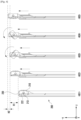
- FIG. 4 is a diagram of an upward operation of a camera module unit, according to an embodiment.
- the camera module unit 210 may perform an upward motion and/or a rotation motion based on a user input (e.g., front photographing converting input or front photographing app execution). As the camera module unit 210 rotates, at least one camera included in the camera module unit 210 may be used as a front camera (e.g., self-camera).
- a front camera e.g., self-camera
- the camera included in the camera module unit 210 may face a rear surface (e.g., third direction, first state) of the electronic device 200.
- the camera included in the camera module unit 210 may be used as a rear camera.
- This state may be referred to as a first state.
- the camera module unit 210, the rack gear rail 222, and the slide portion 230 may perform an upward movement based on the user input.
- the camera module unit 210, the rack gear rail 222, and the slide portion 230 may move by a first length H1.
- the rack gear rail 222 may be fixed by the locking hook 226 and the locking guide 243. This state may be referred to as a second state.
- the camera module unit 210 may perform an upward movement and a rotation movement.
- the rack gear rail 222 may be fixed by the locking hook 226 and the locking guide 243, and only the camera module unit 210 and the slide portion 230 may move upward.
- the camera module unit 210 and the slide portion 230 may move upward by a second length H2.
- the pinion gear 213 may rotate in engagement with the rack gear rail 222. Therefore, the camera module unit 210 may move in rotation.
- a camera included in the camera module unit 210 may face a front surface (e.g., fourth direction and third state) of the electronic device 200. In this case, the camera included in the camera module unit 210 may be used as a front camera. This state may be referred to as a third state.
- FIG. 5 is a diagram of a downward operation of a camera module unit, according to an embodiment.
- the camera module unit 210 may perform a downward operation or a rotation operation based on a user input (e.g., rear photographing switching input or photographing ending input). As the camera module unit 210 rotates, at least one camera included in the camera module unit 210 may be used as a rear camera.
- a user input e.g., rear photographing switching input or photographing ending input.
- the camera included in the camera module unit 210 may face a front surface (e.g., fourth direction and third state) of the electronic device 200.
- the camera included in the camera module unit 210 may face a front surface of the electronic device 200 by a previously input user input (e.g., front photographing switching input or front photographing app execution).
- the camera module unit 210 may perform a downward movement and/or a rotational movement.
- a state may be maintained in which the rack gear rail 222 is fixed by the locking hook 226 and the locking guide 243, and only the camera module unit 210 and the slide portion 230 may move downward.
- the camera module unit 210 and the slide portion 230 may move downward by the second length H2.
- the pinion gear 213 may rotate in engagement with the rack gear rail 222. Therefore, the camera module unit 210 may move in rotation.
- an unexpected external force may be applied to the slide portion 230, and this force may be transferred to the rack gear rail 222; thus, when the rack gear rail 222 moves downward, the camera module unit 210 may be damaged while interfering with the screen unit 240 during a rotation thereof.
- a movement of the locking guide 243 is physically limited in a second direction according to interference, and in the states 501, 502 and 503, the rack gear rail 222 may be prevented from moving downward.
- the slide portion 230 may move downward.
- the camera included in the camera module unit 210 may face a rear surface (e.g., third direction and second state) of the electronic device 200.
- the camera module unit 210, the rack gear rail 222, and the slide portion 230 may perform a downward movement together. In this case, a contact state between the locking hook 226 and the locking guide 243 may be released.
- the camera module unit 210, the rack gear rail 222, and the slide portion 230 may move by the first length H1.
- the camera module unit 210 may return to an original position (e.g., the state 401).
- FIG. 6 is a diagram of a locking guide, according to an embodiment.
- FIG. 7 is a diagram of a locking hook, according to an embodiment.
- the locking hook 226 and the locking guide 243 may protrude toward each other on the same plane (e.g., xy plane) to be disposed to face each other.
- a first inclined plane 243a may be formed based on the illustrated state of FIG. 6 or 7
- a second inclined plane 243b may be formed.
- the first inclined surface 243a may be formed more smoothly than the second inclined surface 243b.
- FIG. 7 illustrates a state (state 402 of FIG. 4 ) in which the rack gear rail 222 moves by a first length H1 (see FIG.
- an inclined surface 226c may be formed at an end portion in the y direction of the locking hook 226, at an end portion in the y direction of the locking hook 226, an inclined surface 226c may be formed.
- a process may be performed smoothly in which the locking hook 226 slides together with the rack gear rail 222 and contacts the first inclined surface 243a or the second inclined surface 243b of the locking guide 243 to couple to or release from the first inclined surface 243a or the second inclined surface 243b.
- a first protrusion 226a and a second protrusion 226b may be formed.
- the first protrusion 226a may protrude toward a front surface (e.g., ?z direction) of the electronic device 200 and be inserted into the first guide slit 224 (see FIG. 8 ) and the second guide slit 225 (see FIG. 8 ) to guide protrusion and return of the locking hook 226.
- the first protrusion 226a may move in the y-axis direction along the second section 224b of the first guide slit 224, and move in the x-axis direction along the second guide slit 225 and the first section 224a of the first guide slit 224.
- the second protrusion 226b may protrude toward the rear surface (e.g., z direction) of the electronic device 200, which is a direction opposite to that of the first protrusion 226a, and be inserted into a third guide slit 227a (see FIG. 8 ) to guide smooth protrusion and return of the locking hook 226.
- a third protrusion 226d may protrude in the same direction as that of the second protrusion 226b and be inserted into a fourth guide slit 227b (see FIG. 3A ) formed in parallel with the third guide slit 227a.
- the locking hook 226 may be prevented from rotating about the second protrusion 226b in a process of protruding and returning.
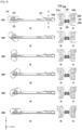
- FIG. 8 is a diagram of an operation of releasing a locking hook and a locking guide in a downward operation of a camera module unit, according to an embodiment. States 801 to 806 are illustrated by subdividing a movement of the locking hook 226 and the locking guide 243 in the states 501 to 504 of FIG. 5 .
- 801-b is a diagram illustrating 801-a viewed in a direction A
- 801-c is a diagram illustrating 801-a viewed in a direction B.
- the up and down direction based on an illustrated state of 801-a may be a direction (e.g., -z direction) in which the lower side faces the front surface of the electronic device in the z-axis direction
- the left and right direction based on an illustrated state of 801-b and 801-c may indicate the x-axis direction
- the up and down direction may indicate the y-axis direction.
- the first guide slit 224 may include a first section 224a and a second section 224b.
- the first section 224a may be formed to be diagonal to a width direction (e.g., x-axis direction) of the rack gear rail 222 and to recede from the locking guide 243.
- the second section 224b may be connected to the first section 224a and be extended in a longitudinal direction (e.g., y-axis direction) of the rack gear rail 222. Coupling and release of the locking hook 226 and the locking guide 243 may be implemented by the first section 224a of the first guide slit 224.
- a length of the first guide slit 224 in the y-axis direction may correspond to a second length H2.
- the first protrusion 226a of the locking hook 226 moves only in the second section 224b of the first guide slit 224.
- a state may be maintained in which the locking hook 226 and the locking guide 243 are coupled to each other.
- the first protrusion 226a of the locking hook 226 moves (e.g., the locking hook 226 may return toward the rack gear rail 222 and move in the x direction) in a direction of receding the locking hook 226 from the guide slit while the first protrusion 226a moves in the first section 224a of the first guide slit 224.
- release of a contact state between the locking hook 226 and the locking guide 243 may be started.
- a movement of the first protrusion 226a of the locking hook 226 is completed within the first section 224a of the first guide slit 224, and a contact state of the locking hook 226 and the locking guide 243 may be released completely. Accordingly, the slide portion 230 may move freely as much as the first length H1 from the state 504 to the state 505 of FIG. 5 .
- FIG. 9 is a diagram of a torsion spring for releasing a locking hook and a locking guide, according to an embodiment.
- FIG. 8 a contact state between the locking hook 226 and the locking guide 243 is gradually released through the first section 224a of the first guide slit 224 formed diagonally.
- FIG. 9 is different in that a contact state of the locking hook 226 and the locking guide 243 is instantaneously released by an elastic force of the torsion spring 229.
- the locking hook 226 and the locking guide 243 may be released. Thereby, the slide portion 230 may be fixed until immediately before a rotation of the camera module unit 210 is completed.
- an electronic device includes a housing, a display positioned in the housing and exposed through a portion of the housing, a slide portion comprising an opening exposed to an outside of the electronic device and configured to slide with respect to the housing, a camera module unit disposed at the opening, configured to rotate within the opening, and to rotate in association with an operation of the slide portion, and a sliding motion controller configured to implement a slide operation of the slide portion and a rotation operation of the camera module unit.
- the sliding motion controller includes a sliding plate coupled to the slide portion to slide together with the slide portion, a rack gear rail disposed in a sliding direction of the slide portion and configured to move together with the slide portion by a first length and having a gear formed at a first end thereof, a locking hook protruding from a second end of the rack gear rail so as to intersect a sliding direction of the rack gear rail, and a locking guide formed to correspond to a position of the locking hook and coupled to the locking hook.
- the slide portion includes a first state in which the camera module unit is positioned to overlap with the display, a second state from movement by a first length in a first direction toward an arbitrary edge of the display in the first state, and a third state from movement by a second length in the first direction in the second state.
- the sliding plate, the rack gear rail, and the locking hook of the sliding motion controller move together, and the locking hook and the locking guide may be coupled to each other to fix the rack gear rail.
- the sliding plate of the sliding motion controller moves may and the camera module rotates.
- the camera module unit may face a third direction in the first state and the second state, face a fourth direction in the third state, and rotate toward a fourth direction different from the third direction when switching from the second state to the third state.
- the third direction and the fourth direction may be opposite to each other.
- a first guide slit including a first section formed diagonally in a width direction of the rack gear rail and a second section formed in a longitudinal direction of the rack gear rail is formed, at the other end of the rack gear rail, a second guide slit are formed in a width direction of the rack gear rail, and in the locking hook, a first protrusion inserted into the first guide slit and the second guide slit to move is be formed.
- a second protrusion of the locking hook may move along the second section of the second guide slit and release the locking hook from the locking guide.
- the locking guide may have a first inclined surface formed to gradually approach the rack gear rail in the first direction.
- the locking guide may have a second inclined surface formed to gradually recede from the rack gear rail in the second direction and to have a steeper slope than that of an inclined surface of the first direction.
- an inclined surface may be formed to correspond to an inclined surface of the locking guide.
- the electronic device may further include a slide drive unit configured to provide a driving force to an operation of the slide portion.
- the camera module unit may include a camera housing including at least one camera device and a pinion gear formed along a rotation axis of the camera housing and configured to engage with a gear of the rack gear rail.
- the sliding motion controller may further include a push rod having one side fixed to the sliding plate and the other side connected to the camera module unit, where the camera module unit may further include an extension portion protruding from the camera housing and formed in a shaft between the pinion gears and configured to receive a force in contact with the push rod to rotate in a rotation hole of the slide portion, and where the push rod may push the camera module unit by a second length in a process of moving from the second state to the third state.
- the pinion gear may rotate on the gear of the rack gear rail to rotate the camera module unit.
- an electronic device may include a housing including a first surface facing in a first direction and a second surface facing in a second direction opposite of the first direction, where the first surface includes a first side having a substantially quadrangular shape and extending in a third direction and having a first length and a second side extending in a fourth direction substantially perpendicular to the third direction and having a second length, and the second surface includes a third side having a quadrangular shape having an area smaller than that of the quadrangular shape of the first side and parallel to the first side and having the first length and a fourth side parallel to the second side and having a third length smaller than the second length.
- the electronic device includes a display disposed inside the housing and visible through the first surface and a camera structure slidable in the fourth direction between a first position and a second position, where the camera structure includes a third surface forming a surface substantially extended to the second surface, the third surface including a fifth side substantially aligned with or adjacent to the first side, and a sixth side substantially in contact with or adjacent to the third side when viewed from above the second surface at the first position.
- the electronic device also includes at least one image sensor facing in the second direction at the first position and rotatable to face in the first direction at the second position, where the first side is positioned between the third side and the fifth side at the second position when viewed from above the second surface.
- the electronic device also includes a drive structure disposed inside the housing and configured to move the camera structure in the fourth direction, a first pinion gear coupled to the camera structure while being rotatable along a first path in the fourth direction, a first rack gear engaged with the first pinion gear while being extended along the first path, a first shaft coupled to or integrally formed with the first rack gear and extending in the fourth direction, and a first hook member connected to the first shaft while being movable in the third direction with respect to the first shaft, where the first hook member includes a first structure protruding from an area of the first shaft in the third direction and a second structure protruding in the first direction or the second direction when viewed from the second surface, and a first rail structure coupled to the camera structure and configured to slidably receive the first shaft, where the first rail structure includes a first guide structure configured to guide the second structure such that the first hook member first moves in the fourth direction and then moves in the third direction while the camera structure moves from the second position to the first position.
- the screen unit may be a concept of collectively referring to both the first surface and the display.
- the third surface is a portion corresponding to an area difference between the slide portion and the rear cover and may correspond to the opening area.
- the rack gear rail may be a concept including both the first rack gear and the first shaft.
- the electronic device may further include a first stopper in contact with the first structure at the second position, and while the camera structure moves from the second position to the first position, the first structure may be first stopped by the first stopper while the first rail structure moves in the y-axis direction, and the first structure may move in the x-axis direction while the first rail structure further moves in the y-axis direction.
- the first hook member may further include a third structure protruding in an opposite direction from the second structure, and while the camera structure further moves from the second position to the first position, the first shaft may contact the first stopper and thus may include a second guide structure for guiding the third structure so that the first hook member moves in the x-axis direction with respect to the first shaft.
- the first guide structure may include first openings and including a first portion extending in the y-axis direction and a second portion extending in a direction forming an acute angle with the y-axis direction, and the second structure may move within the first openings.
- the second guide structure may include a second opening extending in the x-axis direction, and the third structure may move in the second opening.
- the second length may be longer than the first length.
Landscapes
- Engineering & Computer Science (AREA)
- Signal Processing (AREA)
- Theoretical Computer Science (AREA)
- Computer Hardware Design (AREA)
- General Engineering & Computer Science (AREA)
- Multimedia (AREA)
- Human Computer Interaction (AREA)
- Physics & Mathematics (AREA)
- General Physics & Mathematics (AREA)
- Studio Devices (AREA)
Description
- The present disclosure relates generally to an electronic device, and more particularly to an electronic device including a rotatable camera.
- Recently developed electronic devices perform not only a communication function but also a function as an image photographing device. With the rapid development of hardware performance, the performance of a camera module received in the electronic device is also rapidly developing, and the camera module may take a high-resolution image or video as is taken by a professional image photographing device.
-
EP 3651 446 A1 discusses an electronic device which includes a pop-up and rotational camera.US 2007/013555 A1 discusses a mobile communication terminal that includes a terminal body and a camera assembly mounted in the terminal body.US 2005/049019 A1 discusses a sliding-type mobile communication terminal having a camera module interlocking with a sliding motion. - As electronic devices become thinner and areas occupied by displays increase, various studies for an effective space disposition of components (e.g., camera modules) of electronic devices are being actively conducted.
- The present disclosure has been made to address at least the disadvantages described above and to provide at least the advantages described below.
- The invention is set out in the appended set of claims.
- By allowing one camera module to perform a function of a front camera and a rear camera, an electronic device may maximize the display of the electronic device.
- The locking hook and the locking guide limit a movement of the slide portion by a physical locking structure, and in a process of switching to the front camera and the rear camera, even when an unexpected external force is applied, the slide portion may be fixed and the module unit may rotate without interfering with a peripheral structure.
- The above and other aspects, features and advantages of certain embodiments of the disclosure will be more apparent from the following detailed description taken in conjunction with the accompanying drawings, in which:
-
FIG. 1 is a diagram illustrating a configuration of an electronic device in a network environment, according to an embodiment; -
FIG. 2A is an exploded perspective view illustrating an electronic device including a rotatable camera, according to an embodiment; -
FIG. 2B is an exploded perspective view illustrating an electronic device including a rotatable camera at different angles, according to an embodiment; -
FIGS. 3A and3B are views illustrating a sliding motion controller ofFIGS. 2A and2B , according to an embodiment; -
FIG. 4 is a side view illustrating an upward operation of a camera module unit, according to an embodiment disclosure; -
FIG. 5 is a side view illustrating a downward operation of a camera module unit, according to an embodiment; -
FIG. 6 is a diagram illustrating a locking guide, according to an embodiment; -
FIG. 7 is a diagram illustrating a locking hook, according to an embodiment; -
FIG. 8 is a diagram illustrating an operation of releasing a locking hook and a locking guide in a downward operation of a camera module unit, according to an embodiment; and -
FIG. 9 is a diagram illustrating a torsion spring for releasing a locking hook and a locking guide, according to an embodiment. -
FIG. 1 illustrates an electronic device in a network environment according to an embodiment. - Referring to
FIG. 1 , anelectronic device 101 in anetwork environment 100 may communicate with anelectronic device 102 via a first network 198 (e.g., a short-range wireless communication network), or anelectronic device 104 or aserver 108 via a second network 199 (e.g., a long-range wireless communication network). Theelectronic device 101 may communicate with theelectronic device 104 via theserver 108. Theelectronic device 101 includes aprocessor 120,memory 130, aninput device 150, anaudio output device 155, adisplay device 160, anaudio module 170, asensor module 176, aninterface 177, ahaptic module 179, acamera module 180, apower management module 188, abattery 189, acommunication module 190, a subscriber identification module (SIM) 196, and anantenna module 197. At least one of the components may be omitted from theelectronic device 101, or one or more other components may be added in theelectronic device 101. Some of the components may be implemented as single integrated circuitry. For example, thesensor module 176 may be implemented as embedded in thedisplay device 160. - The
processor 120 may execute aprogram 140 to control at least one other hardware or software component of theelectronic device 101 coupled with theprocessor 120, and may perform various data processing or computation. As at least part of the data processing or computation, theprocessor 120 may load a command or data received from another component involatile memory 132, process the command or the data stored in thevolatile memory 132, and store resulting data innon-volatile memory 134. Theprocessor 120 may include a main processor 121 (e.g., a central processing unit (CPU) or an application processor (AP)), and an auxiliary processor 123 (e.g., a graphics processing unit (GPU), an image signal processor (ISP), a sensor hub processor, or a communication processor (CP)) that is operable independently from, or in conjunction with, themain processor 121. Additionally or alternatively, theauxiliary processor 123 may be adapted to consume less power than themain processor 121, or to be specific to a specified function. Theauxiliary processor 123 may be implemented as separate from, or as part of themain processor 121. - The
auxiliary processor 123 may control at least some of functions or states related to at least one component among the components of theelectronic device 101, instead of themain processor 121 while themain processor 121 is in an inactive (e.g., sleep) state, or together with themain processor 121 while themain processor 121 is in an active state. The auxiliary processor 123 (e.g., an ISP or a CP) may be implemented as part of another component (e.g., thecamera module 180 or the communication module 190) functionally related to theauxiliary processor 123. - The
memory 130 may store various data used by at least one component of theelectronic device 101, such as theprogram 140 and input data or output data for a command related thereto. Thememory 130 may include thevolatile memory 132 or thenon-volatile memory 134. - The
program 140 may be stored in thememory 130 as software and may include an operating system (OS) 142,middleware 144, andapplications 146. - The
input device 150 may receive a command or data to be used by theprocessor 120 of theelectronic device 101, from the outside (e.g., a user) of theelectronic device 101. Theinput device 150 may include a microphone, a mouse, a keyboard, or a digital pen. - The
audio output device 155 may output sound signals to the outside of theelectronic device 101 and may include a speaker or a receiver. The speaker may be used for general purposes, such as playing multimedia or playing record, and the receiver may be used for receiving incoming calls. The receiver may be implemented as separate from, or as part of the speaker. - The
display device 160 may visually provide information to the outside (e.g., a user) of theelectronic device 101. Thedisplay device 160 may include a display, a hologram device, or a projector and control circuitry to control a corresponding one of the display, hologram device, and projector. Thedisplay device 160 may include touch circuitry adapted to detect a touch, or sensor circuitry (e.g., a pressure sensor) adapted to measure the intensity of force incurred by the touch. - The
audio module 170 may convert a sound into an electrical signal and vice versa. Theaudio module 170 may obtain the sound via theinput device 150, or output the sound via theaudio output device 155 or a headphone of an external electronic device (e.g., an electronic device 102) directly (e.g., wiredly) or wirelessly coupled with theelectronic device 101. - The
sensor module 176 may detect an operational state (e.g., power or temperature) of theelectronic device 101 or an environmental state (e.g., a state of a user) external to theelectronic device 101, and then generate an electrical signal or data value corresponding to the detected state. Thesensor module 176 may include a gesture sensor, a gyro sensor, an atmospheric pressure sensor, a magnetic sensor, an acceleration sensor, a grip sensor, a proximity sensor, a color sensor, an infrared (IR) sensor, a biometric sensor, a temperature sensor, a humidity sensor, and an illuminance sensor. - The
interface 177 may support one or more specified protocols to be used for theelectronic device 101 to be coupled with the externalelectronic device 102 directly (e.g., wiredly) or wirelessly. Theinterface 177 may include a high definition multimedia interface (HDMI), a universal serial bus (USB) interface, a secure digital (SD) card interface, or an audio interface. - A
connection terminal 178 may include a connector via which theelectronic device 101 may be physically connected with the externalelectronic device 102. Theconnection terminal 178 may include an HDMI connector, a USB connector, an SD card connector, or an audio connector. - The
haptic module 179 may convert an electrical signal into a mechanical stimulus (e.g., a vibration or a movement) or electrical stimulus which may be recognized by a user via his tactile sensation or kinesthetic sensation. Thehaptic module 179 may include a motor, a piezoelectric element, or an electric stimulator. - The
camera module 180 may capture a still image or moving images. Thecamera module 180 may include one or more lenses, image sensors, ISPs, or flashes. - The
power management module 188 may manage power supplied to theelectronic device 101. Thepower management module 188 may be implemented as at least part of a power management integrated circuit (PMIC). - The
battery 189 may supply power to at least one component of theelectronic device 101 and may include a primary cell which is not rechargeable, a secondary cell which is rechargeable, or a fuel cell. - The
communication module 190 may support establishing a direct communication channel or a wireless communication channel between theelectronic device 101 and the external electronic device and performing communication via the established communication channel. Thecommunication module 190 may include one or more CPs that are operable independently from the processor 120 (e.g., the AP) and supports a direct communication or a wireless communication. Thecommunication module 190 may include a wireless communication module 192 (e.g., a cellular communication module, a short-range wireless communication module, or a global navigation satellite system (GNSS) communication module) or a wired communication module 194 (e.g., a local area network (LAN) communication module or a power line communication (PLC) module). A corresponding one of these communication modules may communicate with the external electronic device via the first network 198 (e.g., a short-range communication network, such as Bluetooth™, Wi-Fi direct, or infrared data association (IrDA)) or the second network 199 (e.g., a long-range communication network, such as a cellular network, the Internet, or a computer network (e.g., LAN or wide area network (WAN)). - These various types of communication modules may be implemented as a single component (e.g., a single chip), or may be implemented as multi components (e.g., multi chips) separate from each other. The
wireless communication module 192 may identify and authenticate theelectronic device 101 in a communication network, such as thefirst network 198 or thesecond network 199, using subscriber information (e.g., an international mobile subscriber identity (IMSI)) stored in theSIM 196. - The
antenna module 197 may transmit or receive a signal or power to or from the external electronic device. Theantenna module 197 may include an antenna including a radiating element composed of a conductive material or a conductive pattern formed in or on a substrate (e.g., a printed circuit board (PCB)). Theantenna module 197 may include a plurality of antennas. In such a case, at least one antenna appropriate for a communication scheme used in the communication network, such as thefirst network 198 or thesecond network 199, may be selected by thecommunication module 190 from the plurality of antennas. The signal or the power may then be transmitted or received between thecommunication module 190 and the external electronic device via the selected at least one antenna. Another component (e.g., a radio frequency integrated circuit (RFIC)) other than the radiating element may be additionally formed as part of theantenna module 197. - At least some of the above-described components may be coupled mutually and communicate signals therebetween via an inter-peripheral communication scheme (e.g., a bus, general purpose input and output (GPIO), serial peripheral interface (SPI), or mobile industry processor interface (MIPI)).
- Commands or data may be transmitted or received between the
electronic device 101 and the externalelectronic device 104 via theserver 108 coupled with thesecond network 199. Each of theelectronic devices electronic device 101. All or some of operations to be executed at theelectronic device 101 may be executed at one or more of the externalelectronic devices electronic device 101 should perform a function or a service automatically, or in response to a request from a user or another device, theelectronic device 101, instead of, or in addition to, executing the function or the service, may request the one or more external electronic devices to perform at least part of the function or the service. The one or more external electronic devices receiving the request may perform the at least part of the function or the service requested, or an additional function or an additional service related to the request, and transfer an outcome of the performing to theelectronic device 101. Theelectronic device 101 may provide the outcome, with or without further processing of the outcome, as at least part of a reply to the request. To that end, a cloud, distributed, or client-server computing technology may be used, for example. - An electronic device according to an embodiment may be one of various types of electronic devices, including, but not limited to a portable communication device (e.g., a smart phone), a computer device, a portable multimedia device, a portable medical device, a camera, a wearable device, or a home appliance. However, the electronic device is not limited to any of those described above.
- With regard to the description of the drawings, similar reference numerals may be used to refer to similar or related elements.
- A singular form of a noun corresponding to an item may include one or more of the things, unless the relevant context clearly indicates otherwise. As used herein, each of such phrases as "A or B", "at least one of A and B", "at least one of A or B", "A, B, or C", "at least one of A, B, and C", and "at least one of A, B, or C" may include any one of, or all possible combinations of the items enumerated together in a corresponding one of the phrases.
- As used herein, such terms as "1st" and "2nd", or "first" and "second" may be used to simply distinguish a corresponding component from another, and does not limit the components in other aspect (e.g., importance or order). If an element (e.g., a first element) is referred to, with or without the term "operatively" or "communicatively", as "coupled with", "coupled to", "connected with", or "connected to" another element (e.g., a second element), it means that the element may be coupled with the other element directly (e.g., wiredly), wirelessly, or via a third element.
- The term "module" may include a unit implemented in hardware, software, or firmware, and may interchangeably be used with other terms, for example, "logic", "logic block", "part", or "circuitry". A module may be a single integral component, or a minimum unit or part thereof, adapted to perform one or more functions. For example, according to an embodiment, the module may be implemented in a form of an application-specific integrated circuit (ASIC).
-
FIG. 2A is a diagram of an electronic device including a rotatable camera, according to an embodiment.FIG. 2B is a diagram of an electronic device including a rotatable camera at different angles, according to an embodiment.FIGS. 3A and3B are diagrams of a sliding motion controller ofFIGS. 2A and2B , according to an embodiment. - In describing the
electronic device 200, the same or similar reference numerals may be used for the same or similar elements. In describing theelectronic device 200, a first direction may refer to a -y direction, and a second direction may refer to a y direction. In other words, the first direction is a direction (e.g., -y direction) toward the upper end of theelectronic device 200, and the upper end of theelectronic device 200 may refer to the upper left end of theelectronic device 200 based on the illustrated state ofFIG. 2A . The second direction is a direction (e.g., y direction) toward the lower end of theelectronic device 200, and the lower end of theelectronic device 200 may refer to the lower right end based on the illustrated state ofFIG. 2A . A third direction is a z direction or a direction toward a rear surface of theelectronic device 200 and may refer to a direction toward the upper side based on the illustrated state ofFIG. 2A , and a fourth direction is a -z direction or a direction toward a front surface of theelectronic device 200 and may refer to a direction toward the lower side based on the illustrated state ofFIG. 2A . A lateral direction is a left and right direction (e.g., x-axis direction) of theelectronic device 200 and may refer to a lower left direction or an upper right direction based on the illustrated state ofFIG. 2A . - With reference to
FIGS. 2A and3B , theelectronic device 200 may include acamera module unit 210, a slidingmotion controller 220, aslide portion 230, a slide driver, ascreen unit 240, and arear cover 250. Further, theelectronic device 200 may include one or more other components. - The
electronic device 200 may include ahousing 250 including acamera module unit 210, a slidingmotion controller 220, aslide portion 230, a slide driver (not illustrated), ascreen unit 240, and arear cover 250. The housing may refer to a structure for protecting various electronic components forming an external shape of theelectronic device 200 and mounted in theelectronic device 200. Alternatively, the housing may include an internal structure of theelectronic device 200. - The
camera module unit 210 may include at least onecamera device 216, aflash 217, or asensor module 218. Thecamera module unit 210 may include thecamera module 180 ofFIG. 1 . At least onecamera device 216 may include one or a plurality of lenses, an image sensor, and/or an ISP. Theflash 217 may include a light emitting diode or a xenon lamp. Thesensor module 218 may generate an electrical signal or a data value corresponding to an operating state inside theelectronic device 200 or an external environment state thereof. Thesensor module 218 may include a proximity sensor, an illuminance sensor, and a heart rate monitoring (HRM) sensor. - The
electronic device 200 may further include at least one of a sensor module (not illustrated), such as a gesture sensor, gyro sensor, atmospheric pressure sensor, magnetic sensor, acceleration sensor, grip sensor, color sensor, infrared (IR) sensor, biometric sensor, temperature sensor, humidity sensor, or fingerprint sensor. - The
camera module unit 210 may include acamera housing 211 including at least onecamera device 216, aflash 217, or asensor module 218. Thecamera housing 211 may include apinion gear 213 in at least one side surface thereof. Thepinion gear 213 may be symmetrically disposed at both sides of thecamera housing 211. Anextension portion 215 may be disposed between thecamera housing 211 and thepinion gear 213. Theextension portion 215 and thepinion gear 213 may be integrally formed with thecamera housing 211. - The
slide motion controller 220 may include a slidingplate 221, arack gear rail 222, alocking hook 226, a lockingguide 243, ahook cover 227, and/or apush rod 228. Therack gear rail 222, the lockinghook 226, the lockingguide 243, thehook cover 227, and/or thepush rod 228 may be disposed symmetrically at both sides based on thecamera module unit 210. - The sliding
plate 221 may be coupled to theslide portion 230 to slide together and provide a space in which therack gear rail 222 and thepush rod 228 are disposed. At the end of the first direction of the slidingplate 221, thepush rod 228 may be disposed, and at the end of the second direction thereof, a first guide slit 224 may be disposed. Thepush rod 228 may transport a force to thecamera module unit 210 in a sliding process of theslide portion 230. A first guide slit 224 may include afirst section 224a (seeFIG. 3A ) and asecond section 224b (seeFIG. 3A ). Thefirst section 224a may be formed to be diagonal to a width direction (e.g., the lateral direction of the electronic device, the x direction) of therack gear rail 222 and to recede from the lockingguide 243, and thesecond section 224b may be connected to thefirst section 224a and be extended in a longitudinal direction (e.g., y-axis direction) of therack gear rail 222. The first guide slit 224 may guide a moving direction of afirst protrusion 226a of thelocking hook 226 to be described later to release a contact state between the lockinghook 226 and the lockingguide 243. - The
rack gear rail 222 may be disposed in a direction (e.g., -y direction or first direction) in which theslide portion 230 slides. At one end (e.g., first direction or -y direction) of therack gear rail 222, agear 223 may be formed, and at the other end (e.g., second direction or y direction) of therack gear rail 222, a second guide slit 225 may be formed. Thegear 223 of therack gear rail 222 may engage with thepinion gear 213 of thecamera module unit 210 to convert a force received through thepush rod 228 to a rotational force, thereby rotating thecamera module unit 210. An angle at which thecamera module unit 210 rotates may be adjusted according to a length of therack gear rail 222 or the number of gears. The second guide slit 225 is formed in a width direction (e.g., the lateral direction of the electronic device and the x-axis direction) of therack gear rail 222; thus, the second guide slit 225 may guide thelocking hook 226 protruded in the -x direction to return in the x direction. - The
locking hook 226 may be disposed at the other end of therack gear rail 222. Thelocking hook 226 may be disposed to protrude in a direction crossing a direction (e.g., y-axis direction) in which therack gear rail 222 slides. Thelocking hook 226 may be disposed on the same plane (e.g., xy plane) as that of the lockingguide 243. When thelocking hook 226 is protruding, the lockinghook 226 may be coupled to the lockingguide 243 to prevent therack gear rail 222 from moving in the second direction. The coupling of thelocking hook 226 and the lockingguide 243 is not limited to coupling using physical coupling by fitting or latching or an attractive force by an electromagnetic force. The coupling of thelocking hook 226 and the lockingguide 243 may refer to a state in which a movement of therack gear rail 222 is blocked by interference between the lockinghook 226 and the lockingguide 243 as the lockingguide 243 is positioned on a movement path of therack gear rail 222 including thelocking hook 226. - The
hook cover 227 may cover thelocking hook 226 and be coupled to the other end of therack gear rail 222. In thehook cover 227, athird cover slit 227a may be formed in the same direction to correspond to a position of the second guide slit 225. Thehook cover 227 may guide thelocking hook 226 to protrude and return smoothly while preventing thelocking hook 226 from being separated from therack gear rail 222. - The locking
guide 243 may be disposed on the same plane (e.g., xy plane) as that of thelocking hook 226. At a portion in contact with thelocking hook 226, an inclined surface may be formed and a firstinclined surface 243a in the y direction may be formed more smoothly than a secondinclined surface 243b in the -y direction. When therack gear rail 222 slides in the first direction (e.g., -y direction), therack gear rail 222 may contact the firstinclined surface 243a to move without great resistance, but when therack gear rail 222 moves in the second direction (e.g., y direction), therack gear rail 222 may contact the secondinclined surface 243b (seeFIG. 4 ) having a steep slope to receive large resistance to a slide movement of therack gear rail 222. Therefore, therack gear rail 222 may move in the second direction only when a contact state between the lockinghook 226 and the lockingguide 243 is released first. In a process in which therack gear rail 222 slides in the second direction, a method of releasing thelocking hook 226 and the lockingguide 243 will be described later with reference toFIG. 8 . - The
slide portion 230 may include anopening 231. At an end portion of theslide portion 230 in the first direction (e.g., ?y direction), theopening 231 may be formed in a z-axis direction. Theopening 231 may be formed to correspond to a size of thecamera module unit 210, but it may be formed with a predetermined gap so as to minimize any friction during a rotation of thecamera module unit 210. Thecamera module unit 210 may be disposed in theopening 231. Thecamera module unit 210 according to an embodiment may rotate in theopening 231 using thepinion gear 213 as an axis thereof. - The slide driving unit (not illustrated) may provide a necessary driving force when the
slide portion 230 and the slidingmotion controller 220 move in a first direction (e.g., -y direction) or a second direction (e.g., y direction). The slide driving unit may use a motor, a worm, and a worm gear and use an actuator that performs a linear motion; and any power source capable of providing a driving force for driving theslide portion 230 may be freely applied to the slide driving unit. - The
screen unit 240 may include a display 241 (e.g., thedisplay device 160 ofFIG. 1 ). Thedisplay 241 may be coupled to or be disposed adjacent to a touch detection circuit, a pressure sensor capable of measuring intensity (pressure) of a touch, and/or a digitizer for detecting a magnetic field stylus pen. Because no camera is disposed at thescreen unit 240, thedisplay 241 may be implemented in a maximum area at a front surface of theelectronic device 200. - The
rear cover 250 may cover a portion of theslide portion 230. Theopening 231 may be formed at the upper end in the -y direction of theslide portion 230 that is not covered by therear cover 250. Theslide portion 230 may perform a slide motion between thescreen unit 240 and therear cover 250. Therear cover 250 may be formed by coated or colored glass, ceramic, polymer, metal (e.g., aluminum, stainless steel (STS), or magnesium), or a combination of at least two of the above materials. -
FIG. 4 is a diagram of an upward operation of a camera module unit, according to an embodiment. - With reference to
FIG. 4 , thecamera module unit 210 may perform an upward motion and/or a rotation motion based on a user input (e.g., front photographing converting input or front photographing app execution). As thecamera module unit 210 rotates, at least one camera included in thecamera module unit 210 may be used as a front camera (e.g., self-camera). - In a
state 401, the camera included in thecamera module unit 210 may face a rear surface (e.g., third direction, first state) of theelectronic device 200. In this case, the camera included in thecamera module unit 210 may be used as a rear camera. This state may be referred to as a first state. - In a
state 402, thecamera module unit 210, therack gear rail 222, and theslide portion 230 may perform an upward movement based on the user input. Thecamera module unit 210, therack gear rail 222, and theslide portion 230 may move by a first length H1. In thestate 402, therack gear rail 222 may be fixed by the lockinghook 226 and the lockingguide 243. This state may be referred to as a second state. - In states 403, 404 and 405, the
camera module unit 210 may perform an upward movement and a rotation movement. In thestates rack gear rail 222 may be fixed by the lockinghook 226 and the lockingguide 243, and only thecamera module unit 210 and theslide portion 230 may move upward. Thecamera module unit 210 and theslide portion 230 may move upward by a second length H2. Thepinion gear 213 may rotate in engagement with therack gear rail 222. Therefore, thecamera module unit 210 may move in rotation. In astate 405, a camera included in thecamera module unit 210 may face a front surface (e.g., fourth direction and third state) of theelectronic device 200. In this case, the camera included in thecamera module unit 210 may be used as a front camera. This state may be referred to as a third state. -
FIG. 5 is a diagram of a downward operation of a camera module unit, according to an embodiment. - With reference to
FIG. 5 , thecamera module unit 210 may perform a downward operation or a rotation operation based on a user input (e.g., rear photographing switching input or photographing ending input). As thecamera module unit 210 rotates, at least one camera included in thecamera module unit 210 may be used as a rear camera. - In a
state 501, the camera included in thecamera module unit 210 may face a front surface (e.g., fourth direction and third state) of theelectronic device 200. The camera included in thecamera module unit 210 may face a front surface of theelectronic device 200 by a previously input user input (e.g., front photographing switching input or front photographing app execution). - In the
states camera module unit 210 may perform a downward movement and/or a rotational movement. In thestates rack gear rail 222 is fixed by the lockinghook 226 and the lockingguide 243, and only thecamera module unit 210 and theslide portion 230 may move downward. Thecamera module unit 210 and theslide portion 230 may move downward by the second length H2. Thepinion gear 213 may rotate in engagement with therack gear rail 222. Therefore, thecamera module unit 210 may move in rotation. In this process, an unexpected external force may be applied to theslide portion 230, and this force may be transferred to therack gear rail 222; thus, when therack gear rail 222 moves downward, thecamera module unit 210 may be damaged while interfering with thescreen unit 240 during a rotation thereof. As illustrated inFIG. 5 , in thelocking hook 226 and the lockingguide 243, in a state in which thelocking hook 226 is protruding, a movement of the lockingguide 243 is physically limited in a second direction according to interference, and in thestates rack gear rail 222 may be prevented from moving downward. In other words, in astate 504 in which a rotation of thecamera module unit 210 is completed via thestates slide portion 230 may move downward. - In the
state 504, the camera included in thecamera module unit 210 may face a rear surface (e.g., third direction and second state) of theelectronic device 200. In thestate 504, thecamera module unit 210, therack gear rail 222, and theslide portion 230 may perform a downward movement together. In this case, a contact state between the lockinghook 226 and the lockingguide 243 may be released. Thecamera module unit 210, therack gear rail 222, and theslide portion 230 may move by the first length H1. In thestate 505, thecamera module unit 210 may return to an original position (e.g., the state 401). -
FIG. 6 is a diagram of a locking guide, according to an embodiment.FIG. 7 is a diagram of a locking hook, according to an embodiment. - With reference to
FIGS. 6 and7 , the lockinghook 226 and the lockingguide 243 may protrude toward each other on the same plane (e.g., xy plane) to be disposed to face each other. At the right side (e.g., y direction) of the lockingguide 243, a firstinclined plane 243a may be formed based on the illustrated state ofFIG. 6 or7 , and at the left side of the lockingguide 243, a secondinclined plane 243b may be formed. The firstinclined surface 243a may be formed more smoothly than the secondinclined surface 243b.FIG. 7 illustrates a state (state 402 ofFIG. 4 ) in which therack gear rail 222 moves by a first length H1 (seeFIG. 4 ) together with theslide portion 230 to be fixed by the lockinghook 226 and the lockingguide 243 or a state (states 501 to 503 ofFIG. 5 ) in which thecamera module unit 210 rotates before theslide portion 230 returns to an original state. In this state, as illustrated inFIG. 7 , theinclined surface 226c of thelocking hook 226 may come into contact with the secondinclined surface 243b of the rockingguide 243 having a steep slope to provide large resistance to a slide movement of therack gear rail 222. Therefore, when a contact state of thelocking hook 226 and the lockingguide 243 is released first, therack gear rail 222 may slide smoothly in the second direction. - With reference to
FIG. 7 , at an end portion in the y direction of thelocking hook 226, aninclined surface 226c may be formed. In theinclined surface 226c, a process may be performed smoothly in which thelocking hook 226 slides together with therack gear rail 222 and contacts the firstinclined surface 243a or the secondinclined surface 243b of the lockingguide 243 to couple to or release from the firstinclined surface 243a or the secondinclined surface 243b. - In the
locking hook 226, afirst protrusion 226a and asecond protrusion 226b may be formed. Thefirst protrusion 226a may protrude toward a front surface (e.g., ?z direction) of theelectronic device 200 and be inserted into the first guide slit 224 (seeFIG. 8 ) and the second guide slit 225 (seeFIG. 8 ) to guide protrusion and return of thelocking hook 226. In other words, thefirst protrusion 226a may move in the y-axis direction along thesecond section 224b of the first guide slit 224, and move in the x-axis direction along the second guide slit 225 and thefirst section 224a of the first guide slit 224. Thesecond protrusion 226b may protrude toward the rear surface (e.g., z direction) of theelectronic device 200, which is a direction opposite to that of thefirst protrusion 226a, and be inserted into a third guide slit 227a (seeFIG. 8 ) to guide smooth protrusion and return of thelocking hook 226. Athird protrusion 226d may protrude in the same direction as that of thesecond protrusion 226b and be inserted into a fourth guide slit 227b (seeFIG. 3A ) formed in parallel with thethird guide slit 227a. Thelocking hook 226 may be prevented from rotating about thesecond protrusion 226b in a process of protruding and returning. -
FIG. 8 is a diagram of an operation of releasing a locking hook and a locking guide in a downward operation of a camera module unit, according to an embodiment.States 801 to 806 are illustrated by subdividing a movement of thelocking hook 226 and the lockingguide 243 in thestates 501 to 504 ofFIG. 5 . - With reference to the
state 801 ofFIG. 8 , 801-b is a diagram illustrating 801-a viewed in a direction A, and 801-c is a diagram illustrating 801-a viewed in a direction B. The up and down direction based on an illustrated state of 801-a may be a direction (e.g., -z direction) in which the lower side faces the front surface of the electronic device in the z-axis direction, the left and right direction based on an illustrated state of 801-b and 801-c may indicate the x-axis direction, and the up and down direction may indicate the y-axis direction. - With reference to 801-c of the
state 801 ofFIG. 8 , the first guide slit 224 may include afirst section 224a and asecond section 224b. Thefirst section 224a may be formed to be diagonal to a width direction (e.g., x-axis direction) of therack gear rail 222 and to recede from the lockingguide 243. Thesecond section 224b may be connected to thefirst section 224a and be extended in a longitudinal direction (e.g., y-axis direction) of therack gear rail 222. Coupling and release of thelocking hook 226 and the lockingguide 243 may be implemented by thefirst section 224a of the first guide slit 224. A length of the first guide slit 224 in the y-axis direction may correspond to a second length H2. - When the camera module rotates toward a rear surface of the electronic device, in the states 801-a, 801-b, 801-c, 802-a, 802-b, 802-c, 803-a, 803-b and 803-c in which an amount of rotation is much, the
first protrusion 226a of thelocking hook 226 moves only in thesecond section 224b of the first guide slit 224. Thus, a state may be maintained in which thelocking hook 226 and the lockingguide 243 are coupled to each other. - In the state 804-a, 804-b and 804-c, at a time point in which the
first hook 226a of thelocking hook 226 starts to enter thefirst section 224a of the first guide slit 224, release of a contact state of thelocking hook 226 and the lockingguide 243 may be started. - In the state 805-a, 805-b and 805-c, the
first protrusion 226a of thelocking hook 226 moves (e.g., the lockinghook 226 may return toward therack gear rail 222 and move in the x direction) in a direction of receding thelocking hook 226 from the guide slit while thefirst protrusion 226a moves in thefirst section 224a of the first guide slit 224. Thus, release of a contact state between the lockinghook 226 and the lockingguide 243 may be started. - In the state 806-a, 806-b and 806-c, a movement of the
first protrusion 226a of thelocking hook 226 is completed within thefirst section 224a of the first guide slit 224, and a contact state of thelocking hook 226 and the lockingguide 243 may be released completely. Accordingly, theslide portion 230 may move freely as much as the first length H1 from thestate 504 to thestate 505 ofFIG. 5 . -
FIG. 9 is a diagram of a torsion spring for releasing a locking hook and a locking guide, according to an embodiment. - In
FIG. 8 , a contact state between the lockinghook 226 and the lockingguide 243 is gradually released through thefirst section 224a of the first guide slit 224 formed diagonally. However,FIG. 9 is different in that a contact state of thelocking hook 226 and the lockingguide 243 is instantaneously released by an elastic force of thetorsion spring 229. - By approaching a
state 806 in which a rotation of thecamera module unit 210 is almost completed by quickly changing thestates hook 226 and the lockingguide 243 may be released. Thereby, theslide portion 230 may be fixed until immediately before a rotation of thecamera module unit 210 is completed. - According to an embodiment, an electronic device includes a housing, a display positioned in the housing and exposed through a portion of the housing, a slide portion comprising an opening exposed to an outside of the electronic device and configured to slide with respect to the housing, a camera module unit disposed at the opening, configured to rotate within the opening, and to rotate in association with an operation of the slide portion, and a sliding motion controller configured to implement a slide operation of the slide portion and a rotation operation of the camera module unit. The sliding motion controller includes a sliding plate coupled to the slide portion to slide together with the slide portion, a rack gear rail disposed in a sliding direction of the slide portion and configured to move together with the slide portion by a first length and having a gear formed at a first end thereof, a locking hook protruding from a second end of the rack gear rail so as to intersect a sliding direction of the rack gear rail, and a locking guide formed to correspond to a position of the locking hook and coupled to the locking hook.
- The slide portion includes a first state in which the camera module unit is positioned to overlap with the display, a second state from movement by a first length in a first direction toward an arbitrary edge of the display in the first state, and a third state from movement by a second length in the first direction in the second state.
- When the slide portion moves from the first state to the second state, the sliding plate, the rack gear rail, and the locking hook of the sliding motion controller move together, and the locking hook and the locking guide may be coupled to each other to fix the rack gear rail.
- When the slide portion moves from the second state to the third state, the sliding plate of the sliding motion controller moves may and the camera module rotates.
- The camera module unit may face a third direction in the first state and the second state, face a fourth direction in the third state, and rotate toward a fourth direction different from the third direction when switching from the second state to the third state.
- The third direction and the fourth direction may be opposite to each other.
- In the sliding plate, a first guide slit including a first section formed diagonally in a width direction of the rack gear rail and a second section formed in a longitudinal direction of the rack gear rail is formed, at the other end of the rack gear rail, a second guide slit are formed in a width direction of the rack gear rail, and in the locking hook, a first protrusion inserted into the first guide slit and the second guide slit to move is be formed.
- When the slide portion moves from the third state to the second state, a second protrusion of the locking hook may move along the second section of the second guide slit and release the locking hook from the locking guide.
- The locking guide may have a first inclined surface formed to gradually approach the rack gear rail in the first direction.
- The locking guide may have a second inclined surface formed to gradually recede from the rack gear rail in the second direction and to have a steeper slope than that of an inclined surface of the first direction.
- In an end portion of the first direction of the locking hook and an end portion of the second direction opposite to the first direction, an inclined surface may be formed to correspond to an inclined surface of the locking guide.
- The electronic device may further include a slide drive unit configured to provide a driving force to an operation of the slide portion.
- The camera module unit may include a camera housing including at least one camera device and a pinion gear formed along a rotation axis of the camera housing and configured to engage with a gear of the rack gear rail.
- The sliding motion controller may further include a push rod having one side fixed to the sliding plate and the other side connected to the camera module unit, where the camera module unit may further include an extension portion protruding from the camera housing and formed in a shaft between the pinion gears and configured to receive a force in contact with the push rod to rotate in a rotation hole of the slide portion, and where the push rod may push the camera module unit by a second length in a process of moving from the second state to the third state.
- When the push rod exerts a force on the extension portion, the pinion gear may rotate on the gear of the rack gear rail to rotate the camera module unit.
- According to an embodiment, an electronic device may include a housing including a first surface facing in a first direction and a second surface facing in a second direction opposite of the first direction, where the first surface includes a first side having a substantially quadrangular shape and extending in a third direction and having a first length and a second side extending in a fourth direction substantially perpendicular to the third direction and having a second length, and the second surface includes a third side having a quadrangular shape having an area smaller than that of the quadrangular shape of the first side and parallel to the first side and having the first length and a fourth side parallel to the second side and having a third length smaller than the second length. The electronic device includes a display disposed inside the housing and visible through the first surface and a camera structure slidable in the fourth direction between a first position and a second position, where the camera structure includes a third surface forming a surface substantially extended to the second surface, the third surface including a fifth side substantially aligned with or adjacent to the first side, and a sixth side substantially in contact with or adjacent to the third side when viewed from above the second surface at the first position. The electronic device also includes at least one image sensor facing in the second direction at the first position and rotatable to face in the first direction at the second position, where the first side is positioned between the third side and the fifth side at the second position when viewed from above the second surface. The electronic device also includes a drive structure disposed inside the housing and configured to move the camera structure in the fourth direction, a first pinion gear coupled to the camera structure while being rotatable along a first path in the fourth direction, a first rack gear engaged with the first pinion gear while being extended along the first path, a first shaft coupled to or integrally formed with the first rack gear and extending in the fourth direction, and a first hook member connected to the first shaft while being movable in the third direction with respect to the first shaft, where the first hook member includes a first structure protruding from an area of the first shaft in the third direction and a second structure protruding in the first direction or the second direction when viewed from the second surface, and a first rail structure coupled to the camera structure and configured to slidably receive the first shaft, where the first rail structure includes a first guide structure configured to guide the second structure such that the first hook member first moves in the fourth direction and then moves in the third direction while the camera structure moves from the second position to the first position.
- The screen unit may be a concept of collectively referring to both the first surface and the display. The third surface is a portion corresponding to an area difference between the slide portion and the rear cover and may correspond to the opening area. The rack gear rail may be a concept including both the first rack gear and the first shaft.
- The electronic device may further include a first stopper in contact with the first structure at the second position, and while the camera structure moves from the second position to the first position, the first structure may be first stopped by the first stopper while the first rail structure moves in the y-axis direction, and the first structure may move in the x-axis direction while the first rail structure further moves in the y-axis direction.
- The first hook member may further include a third structure protruding in an opposite direction from the second structure, and while the camera structure further moves from the second position to the first position, the first shaft may contact the first stopper and thus may include a second guide structure for guiding the third structure so that the first hook member moves in the x-axis direction with respect to the first shaft.
- The first guide structure may include first openings and including a first portion extending in the y-axis direction and a second portion extending in a direction forming an acute angle with the y-axis direction, and the second structure may move within the first openings.
- The second guide structure may include a second opening extending in the x-axis direction, and the third structure may move in the second opening.
- The second length may be longer than the first length.
Claims (13)
- An electronic device (101, 200), comprising:a housing (250);a display (160, 241) positioned in the housing and exposed through a portion of the housing;a slide portion (230) comprising an opening exposed to an outside of the electronic device and configured to slide with respect to the housing;a camera module unit (210) disposed at the opening, configured to rotate within the opening, and to rotate in association with an operation of the slide portion, the camera module comprising a pinion gear (213) formed along a rotation axis of the camera module unit; anda sliding motion controller (220) configured to implement a slide operation of the slide portion and a rotation operation of the camera module unit,wherein the sliding motion controller comprises:a sliding plate (221) coupled to the slide portion to slide together with the slide portion;a rack gear rail (222) disposed in a sliding direction of the slide portion and configured to move together with the slide portion by a first length and having a gear formed at a first end thereof, the gear of the rack gear rail being configured to engage with the pinion gear;a locking hook (226) protruding from a second end of the rack gear rail so as to intersect a sliding direction of the rack gear rail; anda locking guide (243) formed to correspond to a position of the locking hook and coupled to the locking hook,wherein the slide portion further comprises:a first state in which the camera module unit is positioned to overlap with the display;a second state from movement by a first length in a first direction toward an arbitrary edge of the display in the first state; anda third state from movement by a second length in the first direction in the second state,wherein in the sliding plate, a first guide slit (224) comprising a first section formed diagonally in a width direction of the rack gear rail and a second section formed in a longitudinal direction of the rack gear rail is formed,wherein at the second end of the rack gear rail, a second guide slit (225) is formed in a width direction of the rack gear rail, andwherein in the locking hook, a first protrusion (226a) inserted into the first guide slit and the second guide slit to move is formed.
- The electronic device (101, 200) of claim 1, wherein, when the slide portion (230) moves from the first state to the second state, the sliding plate (221), the rack gear rail (222), and the locking hook (226) of the sliding motion controller (220) move together, and the locking hook and the locking guide (243) are coupled to each other to fix the rack gear rail.
- The electronic device (101, 200) of claim 2, wherein, when the slide portion (230) moves from the second state to the third state, the sliding plate (221) of the sliding motion controller (220) moves and the camera module unit (210) rotates.
- The electronic device (101, 200) of claim 3, wherein the camera module unit (210) faces a third direction in the first state and the second state, faces a fourth direction in the third state, and rotates toward the fourth direction when switching from the second state to the third state.
- The electronic device (101, 200) of claim 4, wherein the third direction and the fourth direction are opposite to each other.
- The electronic device (101, 200) of claim 1, wherein, when the slide portion (230) moves from the third state to the second state, a second protrusion (226b) of the locking hook moves along the second section of the second guide slit (225) and releases the locking hook (226) from the locking guide.
- The electronic device (101, 200) of claim 6, wherein the locking guide (243) has a first inclined surface formed to gradually approach the rack gear rail (222) in the first direction.
- The electronic device (101, 200) of claim 7, wherein the locking guide (243) has a second inclined surface formed to gradually recede from the rack gear rail (222) in the second direction and to have a steeper slope than that of an inclined surface of the first direction.
- The electronic device (101, 200) of claim 7, wherein in an end portion of the first direction of the locking hook (226) and an end portion of the second direction opposite to the first direction, an inclined surface is formed to correspond to an inclined surface of the locking guide (243).
- The electronic device (101, 200) of claim 1, further comprising a slide drive unit configured to provide a driving force to an operation of the slide portion (230).
- The electronic device (101, 200) of claim 10, wherein the camera module unit (210) comprises:
a camera housing (211) comprising at least one camera device (216). - The electronic device (101, 200) of claim 11, wherein the sliding motion controller (220) further comprises a push rod (228) having a first side fixed to the sliding plate (221) and a second side connected to the camera module unit (210),wherein the camera module unit further comprises an extension portion (215) protruding from the camera housing (211) and formed in a shaft between the pinion gear (213) and a further pinion gear and configured to receive a force in contact with the push rod to rotate in a rotation hole of the slide portion, andwherein the push rod pushes the camera module unit by a second length in a process of moving from the second state to the third state.
- The electronic device (101, 200) of claim 12, wherein the pinion gear (213) rotates on the gear of the rack gear rail (222) to rotate the camera module unit when the push rod (228) exerts a force on the extension portion (215).
Applications Claiming Priority (2)
| Application Number | Priority Date | Filing Date | Title |
|---|---|---|---|
| KR1020190041342A KR102648987B1 (en) | 2019-04-09 | 2019-04-09 | Electronic device including rotatable camera |
| PCT/KR2020/002864 WO2020209501A1 (en) | 2019-04-09 | 2020-02-28 | Electronic device including rotatable camera |
Publications (3)
| Publication Number | Publication Date |
|---|---|
| EP3878165A1 EP3878165A1 (en) | 2021-09-15 |
| EP3878165A4 EP3878165A4 (en) | 2021-12-22 |
| EP3878165B1 true EP3878165B1 (en) | 2024-11-13 |
Family
ID=72747476
Family Applications (1)
| Application Number | Title | Priority Date | Filing Date |
|---|---|---|---|
| EP20788629.2A Active EP3878165B1 (en) | 2019-04-09 | 2020-02-28 | Electronic device including rotatable camera |
Country Status (5)
| Country | Link |
|---|---|
| US (1) | US11553069B2 (en) |
| EP (1) | EP3878165B1 (en) |
| KR (1) | KR102648987B1 (en) |
| CN (1) | CN113661697B (en) |
| WO (1) | WO2020209501A1 (en) |
Families Citing this family (9)
| Publication number | Priority date | Publication date | Assignee | Title |
|---|---|---|---|---|
| KR102481292B1 (en) * | 2018-04-13 | 2022-12-26 | 삼성전자주식회사 | Electronic device including flexible display |
| KR102925160B1 (en) * | 2019-03-28 | 2026-02-09 | 삼성디스플레이 주식회사 | Dispcay device |
| KR102631112B1 (en) * | 2019-04-30 | 2024-01-30 | 삼성전자 주식회사 | Electric device including rotating camera |
| KR102736654B1 (en) * | 2019-06-04 | 2024-12-02 | 삼성전자주식회사 | Method for authenticating user using a plurality of sensors and electronic device for supporting the same |
| KR102660800B1 (en) * | 2019-07-02 | 2024-04-26 | 삼성전자주식회사 | Electric device including rotation camera |
| CN111427419B (en) * | 2020-03-18 | 2021-11-23 | 维沃移动通信有限公司 | Overturning functional component and electronic equipment |
| CN112782913B (en) * | 2020-12-30 | 2022-04-22 | 深圳市火乐科技发展有限公司 | Dynamic diffusion sheet assembly, control method, laser speckle-dispersing device and projector |
| US11812127B2 (en) * | 2021-10-27 | 2023-11-07 | Dell Products L.P. | Monitor with integrated camera to achieve optimized vertical dimension |
| CN115671465B (en) * | 2022-10-27 | 2025-09-30 | 中国人民解放军陆军军医大学第二附属医院 | A ventilator |
Family Cites Families (21)
| Publication number | Priority date | Publication date | Assignee | Title |
|---|---|---|---|---|
| KR100551426B1 (en) * | 2003-08-27 | 2006-02-09 | 주식회사 팬택앤큐리텔 | Sliding mobile communication terminal with camera interlock |
| KR100593544B1 (en) * | 2004-01-09 | 2006-06-28 | 주식회사 팬택 | Auto open / close slide type mobile communication terminal |
| KR20060035478A (en) | 2004-10-22 | 2006-04-26 | 엘지전자 주식회사 | Sliding type mobile phone |
| KR100733032B1 (en) * | 2005-07-15 | 2007-06-28 | 엘지전자 주식회사 | Mobile communication terminal with camera assembly and camera |
| CN1941795A (en) * | 2005-09-30 | 2007-04-04 | 乐金电子(中国)研究开发中心有限公司 | Portable terminal with camera |
| KR20070068726A (en) | 2005-12-27 | 2007-07-02 | 주식회사 팬택앤큐리텔 | Mobile communication terminal with rotating and sliding display module |
| KR200414532Y1 (en) * | 2006-02-08 | 2006-04-21 | 엘지전자 주식회사 | Mobile communication terminal |
| KR102055204B1 (en) | 2013-09-09 | 2019-12-12 | 엘지전자 주식회사 | Display device including camera module |
| EP2891942B1 (en) * | 2014-01-02 | 2018-08-22 | LG Electronics Inc. | Wearable terminal |
| US9798359B2 (en) | 2014-02-21 | 2017-10-24 | Samsung Electronics Co., Ltd. | Foldable device |
| KR101727971B1 (en) | 2014-02-21 | 2017-04-18 | 삼성전자주식회사 | Foldable device |
| KR102309411B1 (en) * | 2014-10-27 | 2021-10-06 | 엘지전자 주식회사 | Protable electronic device |
| KR101649664B1 (en) * | 2015-03-20 | 2016-08-22 | 엘지전자 주식회사 | Mobile terminal |
| US10320101B2 (en) * | 2015-06-10 | 2019-06-11 | Fairphone B.V. | Connector for an electronic device |
| US10681193B2 (en) * | 2017-10-13 | 2020-06-09 | Guangdong Oppo Mobile Telecommunications Corp., Ltd | Mobile terminal |
| US10498869B2 (en) * | 2017-10-24 | 2019-12-03 | Guangdong Oppo Mobile Telecommunications Corp., Ltd. | Mobile terminal and electronic device |
| CN107888809A (en) * | 2017-11-07 | 2018-04-06 | 广东欧珀移动通信有限公司 | Camera package assembly and mobile terminal |
| CN207926665U (en) * | 2018-02-09 | 2018-09-28 | 广东欧珀移动通信有限公司 | mobile terminal |
| CN110324447B (en) * | 2018-03-31 | 2021-05-28 | Oppo广东移动通信有限公司 | Electronic device and control method of electronic device |
| KR102471644B1 (en) * | 2018-11-09 | 2022-11-29 | 삼성전자주식회사 | Pop-up and rotation camera and electric device including the same |
| KR102106296B1 (en) * | 2018-11-29 | 2020-05-04 | 삼성전자주식회사 | Electric device including camera and operating method thereof |
-
2019
- 2019-04-09 KR KR1020190041342A patent/KR102648987B1/en active Active
-
2020
- 2020-02-28 WO PCT/KR2020/002864 patent/WO2020209501A1/en not_active Ceased
- 2020-02-28 CN CN202080026486.XA patent/CN113661697B/en active Active
- 2020-02-28 EP EP20788629.2A patent/EP3878165B1/en active Active
- 2020-04-02 US US16/838,457 patent/US11553069B2/en active Active
Also Published As
| Publication number | Publication date |
|---|---|
| KR20200119031A (en) | 2020-10-19 |
| EP3878165A1 (en) | 2021-09-15 |
| KR102648987B1 (en) | 2024-03-19 |
| EP3878165A4 (en) | 2021-12-22 |
| CN113661697A (en) | 2021-11-16 |
| US20200329131A1 (en) | 2020-10-15 |
| WO2020209501A1 (en) | 2020-10-15 |
| US11553069B2 (en) | 2023-01-10 |
| CN113661697B (en) | 2024-09-24 |
Similar Documents
| Publication | Publication Date | Title |
|---|---|---|
| US11553069B2 (en) | Electronic device including rotatable camera | |
| KR102668216B1 (en) | Foldable electronic device including hinge assembly | |
| US10944853B2 (en) | Electronic device including slidable body | |
| US11191195B2 (en) | Electronic device including magnet and magnetic shield | |
| EP4156705B1 (en) | Electronic device including pop-up and rotational camera | |
| KR20200121151A (en) | An foldable electronic device including a sliding module and control method | |
| CN111684388A (en) | Electronic device including display with switch | |
| US11363712B2 (en) | Flexible printed circuit board and electronic device including the same | |
| US11799996B2 (en) | Electronic device including camera pop-up structure | |
| US12498766B2 (en) | Hinge assembly and electronic device including the same | |
| KR102784343B1 (en) | Electronic device including display rolling guide structure | |
| EP3952262A1 (en) | Electronic device comprising rotating camera | |
| KR102514401B1 (en) | The electronic device including the connector for attaching the accessory device | |
| KR102899638B1 (en) | Printed circuit board assembly and electronic device including the same | |
| KR20210022921A (en) | Sliding operated electronic device | |
| EP4174618B1 (en) | Electronic apparatus including rollable or slidable display | |
| CN118541964A (en) | Hinge assembly and electronic device including the same |
Legal Events
| Date | Code | Title | Description |
|---|---|---|---|
| STAA | Information on the status of an ep patent application or granted ep patent |
Free format text: STATUS: THE INTERNATIONAL PUBLICATION HAS BEEN MADE |
|
| PUAI | Public reference made under article 153(3) epc to a published international application that has entered the european phase |
Free format text: ORIGINAL CODE: 0009012 |
|
| STAA | Information on the status of an ep patent application or granted ep patent |
Free format text: STATUS: REQUEST FOR EXAMINATION WAS MADE |
|
| 17P | Request for examination filed |
Effective date: 20210607 |
|
| AK | Designated contracting states |
Kind code of ref document: A1 Designated state(s): AL AT BE BG CH CY CZ DE DK EE ES FI FR GB GR HR HU IE IS IT LI LT LU LV MC MK MT NL NO PL PT RO RS SE SI SK SM TR |
|
| A4 | Supplementary search report drawn up and despatched |
Effective date: 20211118 |
|
| RIC1 | Information provided on ipc code assigned before grant |
Ipc: G06F 1/16 20060101ALI20211112BHEP Ipc: H04N 5/225 20060101ALI20211112BHEP Ipc: H04M 1/02 20060101AFI20211112BHEP |
|
| DAV | Request for validation of the european patent (deleted) | ||
| DAX | Request for extension of the european patent (deleted) | ||
| REG | Reference to a national code |
Ref country code: DE Ref legal event code: R079 Free format text: PREVIOUS MAIN CLASS: H04M0001020000 Ipc: H04N0023500000 Ref country code: DE Ref legal event code: R079 Ref document number: 602020041379 Country of ref document: DE Free format text: PREVIOUS MAIN CLASS: H04M0001020000 Ipc: H04N0023500000 |
|
| RIC1 | Information provided on ipc code assigned before grant |
Ipc: H04N 23/57 20230101ALI20240516BHEP Ipc: G06F 1/16 20060101ALI20240516BHEP Ipc: H04M 1/02 20060101ALI20240516BHEP Ipc: H04N 23/50 20230101AFI20240516BHEP |
|
| GRAP | Despatch of communication of intention to grant a patent |
Free format text: ORIGINAL CODE: EPIDOSNIGR1 |
|
| STAA | Information on the status of an ep patent application or granted ep patent |
Free format text: STATUS: GRANT OF PATENT IS INTENDED |
|
| INTG | Intention to grant announced |
Effective date: 20240624 |
|
| RIN1 | Information on inventor provided before grant (corrected) |
Inventor name: CHUN, HONGMOON Inventor name: CHO, CHAEYANG Inventor name: BAE, CHULHO Inventor name: YOO, CHUNGKEUN Inventor name: HAN, YONGHWA |
|
| GRAS | Grant fee paid |
Free format text: ORIGINAL CODE: EPIDOSNIGR3 |
|
| GRAA | (expected) grant |
Free format text: ORIGINAL CODE: 0009210 |
|
| STAA | Information on the status of an ep patent application or granted ep patent |
Free format text: STATUS: THE PATENT HAS BEEN GRANTED |
|
| AK | Designated contracting states |
Kind code of ref document: B1 Designated state(s): AL AT BE BG CH CY CZ DE DK EE ES FI FR GB GR HR HU IE IS IT LI LT LU LV MC MK MT NL NO PL PT RO RS SE SI SK SM TR |
|
| REG | Reference to a national code |
Ref country code: GB Ref legal event code: FG4D |
|
| REG | Reference to a national code |
Ref country code: CH Ref legal event code: EP |
|
| REG | Reference to a national code |
Ref country code: IE Ref legal event code: FG4D |
|
| REG | Reference to a national code |
Ref country code: DE Ref legal event code: R096 Ref document number: 602020041379 Country of ref document: DE |
|
| REG | Reference to a national code |
Ref country code: LT Ref legal event code: MG9D |
|
| REG | Reference to a national code |
Ref country code: NL Ref legal event code: MP Effective date: 20241113 |
|
| PG25 | Lapsed in a contracting state [announced via postgrant information from national office to epo] |
Ref country code: IS Free format text: LAPSE BECAUSE OF FAILURE TO SUBMIT A TRANSLATION OF THE DESCRIPTION OR TO PAY THE FEE WITHIN THE PRESCRIBED TIME-LIMIT Effective date: 20250313 Ref country code: PT Free format text: LAPSE BECAUSE OF FAILURE TO SUBMIT A TRANSLATION OF THE DESCRIPTION OR TO PAY THE FEE WITHIN THE PRESCRIBED TIME-LIMIT Effective date: 20250313 Ref country code: HR Free format text: LAPSE BECAUSE OF FAILURE TO SUBMIT A TRANSLATION OF THE DESCRIPTION OR TO PAY THE FEE WITHIN THE PRESCRIBED TIME-LIMIT Effective date: 20241113 |
|
| PGFP | Annual fee paid to national office [announced via postgrant information from national office to epo] |
Ref country code: DE Payment date: 20250120 Year of fee payment: 6 |
|
| PG25 | Lapsed in a contracting state [announced via postgrant information from national office to epo] |
Ref country code: FI Free format text: LAPSE BECAUSE OF FAILURE TO SUBMIT A TRANSLATION OF THE DESCRIPTION OR TO PAY THE FEE WITHIN THE PRESCRIBED TIME-LIMIT Effective date: 20241113 Ref country code: NL Free format text: LAPSE BECAUSE OF FAILURE TO SUBMIT A TRANSLATION OF THE DESCRIPTION OR TO PAY THE FEE WITHIN THE PRESCRIBED TIME-LIMIT Effective date: 20241113 |
|
| REG | Reference to a national code |
Ref country code: AT Ref legal event code: MK05 Ref document number: 1742556 Country of ref document: AT Kind code of ref document: T Effective date: 20241113 |
|
| PG25 | Lapsed in a contracting state [announced via postgrant information from national office to epo] |
Ref country code: BG Free format text: LAPSE BECAUSE OF FAILURE TO SUBMIT A TRANSLATION OF THE DESCRIPTION OR TO PAY THE FEE WITHIN THE PRESCRIBED TIME-LIMIT Effective date: 20241113 |
|
| PG25 | Lapsed in a contracting state [announced via postgrant information from national office to epo] |
Ref country code: ES Free format text: LAPSE BECAUSE OF FAILURE TO SUBMIT A TRANSLATION OF THE DESCRIPTION OR TO PAY THE FEE WITHIN THE PRESCRIBED TIME-LIMIT Effective date: 20241113 |
|
| PG25 | Lapsed in a contracting state [announced via postgrant information from national office to epo] |
Ref country code: NO Free format text: LAPSE BECAUSE OF FAILURE TO SUBMIT A TRANSLATION OF THE DESCRIPTION OR TO PAY THE FEE WITHIN THE PRESCRIBED TIME-LIMIT Effective date: 20250213 |
|
| PG25 | Lapsed in a contracting state [announced via postgrant information from national office to epo] |
Ref country code: LV Free format text: LAPSE BECAUSE OF FAILURE TO SUBMIT A TRANSLATION OF THE DESCRIPTION OR TO PAY THE FEE WITHIN THE PRESCRIBED TIME-LIMIT Effective date: 20241113 Ref country code: GR Free format text: LAPSE BECAUSE OF FAILURE TO SUBMIT A TRANSLATION OF THE DESCRIPTION OR TO PAY THE FEE WITHIN THE PRESCRIBED TIME-LIMIT Effective date: 20250214 Ref country code: AT Free format text: LAPSE BECAUSE OF FAILURE TO SUBMIT A TRANSLATION OF THE DESCRIPTION OR TO PAY THE FEE WITHIN THE PRESCRIBED TIME-LIMIT Effective date: 20241113 |
|
| PG25 | Lapsed in a contracting state [announced via postgrant information from national office to epo] |
Ref country code: PL Free format text: LAPSE BECAUSE OF FAILURE TO SUBMIT A TRANSLATION OF THE DESCRIPTION OR TO PAY THE FEE WITHIN THE PRESCRIBED TIME-LIMIT Effective date: 20241113 |
|
| PG25 | Lapsed in a contracting state [announced via postgrant information from national office to epo] |
Ref country code: RS Free format text: LAPSE BECAUSE OF FAILURE TO SUBMIT A TRANSLATION OF THE DESCRIPTION OR TO PAY THE FEE WITHIN THE PRESCRIBED TIME-LIMIT Effective date: 20250213 |
|
| PG25 | Lapsed in a contracting state [announced via postgrant information from national office to epo] |
Ref country code: SM Free format text: LAPSE BECAUSE OF FAILURE TO SUBMIT A TRANSLATION OF THE DESCRIPTION OR TO PAY THE FEE WITHIN THE PRESCRIBED TIME-LIMIT Effective date: 20241113 |
|
| PG25 | Lapsed in a contracting state [announced via postgrant information from national office to epo] |
Ref country code: DK Free format text: LAPSE BECAUSE OF FAILURE TO SUBMIT A TRANSLATION OF THE DESCRIPTION OR TO PAY THE FEE WITHIN THE PRESCRIBED TIME-LIMIT Effective date: 20241113 |
|
| PG25 | Lapsed in a contracting state [announced via postgrant information from national office to epo] |
Ref country code: EE Free format text: LAPSE BECAUSE OF FAILURE TO SUBMIT A TRANSLATION OF THE DESCRIPTION OR TO PAY THE FEE WITHIN THE PRESCRIBED TIME-LIMIT Effective date: 20241113 |
|
| PG25 | Lapsed in a contracting state [announced via postgrant information from national office to epo] |
Ref country code: RO Free format text: LAPSE BECAUSE OF FAILURE TO SUBMIT A TRANSLATION OF THE DESCRIPTION OR TO PAY THE FEE WITHIN THE PRESCRIBED TIME-LIMIT Effective date: 20241113 |
|
| PG25 | Lapsed in a contracting state [announced via postgrant information from national office to epo] |
Ref country code: SK Free format text: LAPSE BECAUSE OF FAILURE TO SUBMIT A TRANSLATION OF THE DESCRIPTION OR TO PAY THE FEE WITHIN THE PRESCRIBED TIME-LIMIT Effective date: 20241113 |
|
| PG25 | Lapsed in a contracting state [announced via postgrant information from national office to epo] |
Ref country code: CZ Free format text: LAPSE BECAUSE OF FAILURE TO SUBMIT A TRANSLATION OF THE DESCRIPTION OR TO PAY THE FEE WITHIN THE PRESCRIBED TIME-LIMIT Effective date: 20241113 |
|
| PG25 | Lapsed in a contracting state [announced via postgrant information from national office to epo] |
Ref country code: IT Free format text: LAPSE BECAUSE OF FAILURE TO SUBMIT A TRANSLATION OF THE DESCRIPTION OR TO PAY THE FEE WITHIN THE PRESCRIBED TIME-LIMIT Effective date: 20241113 |
|
| REG | Reference to a national code |
Ref country code: DE Ref legal event code: R097 Ref document number: 602020041379 Country of ref document: DE |
|
| PG25 | Lapsed in a contracting state [announced via postgrant information from national office to epo] |
Ref country code: SE Free format text: LAPSE BECAUSE OF FAILURE TO SUBMIT A TRANSLATION OF THE DESCRIPTION OR TO PAY THE FEE WITHIN THE PRESCRIBED TIME-LIMIT Effective date: 20241113 |
|
| PG25 | Lapsed in a contracting state [announced via postgrant information from national office to epo] |
Ref country code: MC Free format text: LAPSE BECAUSE OF FAILURE TO SUBMIT A TRANSLATION OF THE DESCRIPTION OR TO PAY THE FEE WITHIN THE PRESCRIBED TIME-LIMIT Effective date: 20241113 |
|
| PLBE | No opposition filed within time limit |
Free format text: ORIGINAL CODE: 0009261 |
|
| STAA | Information on the status of an ep patent application or granted ep patent |
Free format text: STATUS: NO OPPOSITION FILED WITHIN TIME LIMIT |
|
| REG | Reference to a national code |
Ref country code: CH Ref legal event code: PL |
|
| PG25 | Lapsed in a contracting state [announced via postgrant information from national office to epo] |
Ref country code: LU Free format text: LAPSE BECAUSE OF NON-PAYMENT OF DUE FEES Effective date: 20250228 |
|
| PG25 | Lapsed in a contracting state [announced via postgrant information from national office to epo] |
Ref country code: CH Free format text: LAPSE BECAUSE OF NON-PAYMENT OF DUE FEES Effective date: 20250228 |
|
| 26N | No opposition filed |
Effective date: 20250814 |
|
| GBPC | Gb: european patent ceased through non-payment of renewal fee |
Effective date: 20250228 |
|
| REG | Reference to a national code |
Ref country code: BE Ref legal event code: MM Effective date: 20250228 |
|
| PG25 | Lapsed in a contracting state [announced via postgrant information from national office to epo] |
Ref country code: GB Free format text: LAPSE BECAUSE OF NON-PAYMENT OF DUE FEES Effective date: 20250228 |
|
| PG25 | Lapsed in a contracting state [announced via postgrant information from national office to epo] |
Ref country code: FR Free format text: LAPSE BECAUSE OF NON-PAYMENT OF DUE FEES Effective date: 20250228 |
|
| PG25 | Lapsed in a contracting state [announced via postgrant information from national office to epo] |
Ref country code: BE Free format text: LAPSE BECAUSE OF NON-PAYMENT OF DUE FEES Effective date: 20250228 |
|
| PG25 | Lapsed in a contracting state [announced via postgrant information from national office to epo] |
Ref country code: IE Free format text: LAPSE BECAUSE OF NON-PAYMENT OF DUE FEES Effective date: 20250228 |