EP3876598A1 - Extended discontinous reception signaling for connected mode user equipments - Google Patents
Extended discontinous reception signaling for connected mode user equipments Download PDFInfo
- Publication number
- EP3876598A1 EP3876598A1 EP21153484.7A EP21153484A EP3876598A1 EP 3876598 A1 EP3876598 A1 EP 3876598A1 EP 21153484 A EP21153484 A EP 21153484A EP 3876598 A1 EP3876598 A1 EP 3876598A1
- Authority
- EP
- European Patent Office
- Prior art keywords
- drx cycle
- value
- extended
- drx
- offset
- Prior art date
- Legal status (The legal status is an assumption and is not a legal conclusion. Google has not performed a legal analysis and makes no representation as to the accuracy of the status listed.)
- Granted
Links
Images
Classifications
-
- H—ELECTRICITY
- H04—ELECTRIC COMMUNICATION TECHNIQUE
- H04W—WIRELESS COMMUNICATION NETWORKS
- H04W76/00—Connection management
- H04W76/20—Manipulation of established connections
- H04W76/28—Discontinuous transmission [DTX]; Discontinuous reception [DRX]
-
- H—ELECTRICITY
- H04—ELECTRIC COMMUNICATION TECHNIQUE
- H04W—WIRELESS COMMUNICATION NETWORKS
- H04W52/00—Power management, e.g. Transmission Power Control [TPC] or power classes
- H04W52/02—Power saving arrangements
- H04W52/0209—Power saving arrangements in terminal devices
- H04W52/0212—Power saving arrangements in terminal devices managed by the network, e.g. network or access point is leader and terminal is follower
- H04W52/0216—Power saving arrangements in terminal devices managed by the network, e.g. network or access point is leader and terminal is follower using a pre-established activity schedule, e.g. traffic indication frame
-
- H—ELECTRICITY
- H04—ELECTRIC COMMUNICATION TECHNIQUE
- H04W—WIRELESS COMMUNICATION NETWORKS
- H04W28/00—Network traffic management; Network resource management
- H04W28/16—Central resource management; Negotiation of resources or communication parameters, e.g. negotiating bandwidth or QoS [Quality of Service]
- H04W28/18—Negotiating wireless communication parameters
-
- H—ELECTRICITY
- H04—ELECTRIC COMMUNICATION TECHNIQUE
- H04W—WIRELESS COMMUNICATION NETWORKS
- H04W84/00—Network topologies
- H04W84/02—Hierarchically pre-organised networks, e.g. paging networks, cellular networks, WLAN [Wireless Local Area Network] or WLL [Wireless Local Loop]
- H04W84/04—Large scale networks; Deep hierarchical networks
- H04W84/042—Public Land Mobile systems, e.g. cellular systems
-
- Y—GENERAL TAGGING OF NEW TECHNOLOGICAL DEVELOPMENTS; GENERAL TAGGING OF CROSS-SECTIONAL TECHNOLOGIES SPANNING OVER SEVERAL SECTIONS OF THE IPC; TECHNICAL SUBJECTS COVERED BY FORMER USPC CROSS-REFERENCE ART COLLECTIONS [XRACs] AND DIGESTS
- Y02—TECHNOLOGIES OR APPLICATIONS FOR MITIGATION OR ADAPTATION AGAINST CLIMATE CHANGE
- Y02D—CLIMATE CHANGE MITIGATION TECHNOLOGIES IN INFORMATION AND COMMUNICATION TECHNOLOGIES [ICT], I.E. INFORMATION AND COMMUNICATION TECHNOLOGIES AIMING AT THE REDUCTION OF THEIR OWN ENERGY USE
- Y02D30/00—Reducing energy consumption in communication networks
- Y02D30/70—Reducing energy consumption in communication networks in wireless communication networks
Definitions
- the present invention relates to extended discontinuous reception (DRX) signaling for connected mode user equipments (UEs).
- DRX discontinuous reception
- DRX For UE energy saving purpose, DRX has been defined in LTE. If an UE is configured with DRX by higher layer, the UE is not required to monitor PDCCH when it is not in active time as show in Fig. 1.
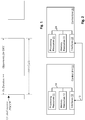
- Fig. 1 illustrates a DRX cycle in which the UE monitors PDCCH during "On Duration" (active time), and does not monitor PDCCH during "Opportunity for DRX".
- longDRX-CycleStartOffset comprises longDRX-Cycle and drxStartOffset.
- the value of longDRX-Cycle is in number of sub-frames.
- Value sf10 corresponds to 10 sub-frames
- sf20 corresponds to 20 sub-frames and so on. If shortDRX-Cycle is configured, the value of longDRX-Cycle should be a multiple of the shortDRX-Cycle value.
- the value of drxStartOffset value is in number of sub-frames.
- onDurationTimer is a timer for DRX. Its value is in number of PDCCH sub-frames. Value psf1 corresponds to 1 PDCCH sub-frame, psf2 corresponds to 2 PDCCH sub-frames and so on.
- the above parameter "drx-InactivityTimer” is a timer for DRX. Its value is in number of PDCCH sub-frames. Value psf1 corresponds to 1 PDCCH sub-frame, psf2 corresponds to 2 PDCCH sub-frames and so on.
- the above parameter "drx-RetransmissionTimer” is a timer for DRX. Its value is in number of PDCCH sub-frames. Value psf1 corresponds to 1 PDCCH sub-frame, psf2 corresponds to 2 PDCCH sub-frames and so on.
- sf2 corresponds to 2 sub-frames
- sf5 corresponds to 5 subframes and so on.
- the above parameter "drxShortCycleTimer” is a timer for DRX. Its value is in multiples of shortDRX-Cycle. A value of 1 corresponds to shortDRX-Cycle, a value of 2 corresponds to 2 * shortDRX-Cycle and so on.
- RAN is considering extending connected mode DRX way beyond the current maximum of 2560ms, e.g. to one hour.
- the number of ms within a cycle is largely superior to the number of UEs that can be supported. For instance, only 65,536 C-RNTI can be allocated (16 bits long), which is to be compared to the 3,600,000 possible offsets in the example of the 1 hour DRX cycle above: ⁇ 100 times more offsets than required.
- extended DRX is introduced with minimized signaling overhead and without compromising flexibility.
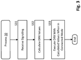
- FIG. 2 for illustrating a simplified block diagram of a control unit 10 and a control unit 20 suitable for use in practicing the exemplary embodiments of this invention.
- the control unit 10 may be part of and/or used by a user equipment.
- the control unit 10 comprises processing resources (e.g. processing circuitry) 11, memory resources (e.g. memory circuitry) 12 which may store a program, and interfaces (e.g. interface circuitry) 13, which are connected via a link 14.
- the interfaces 13 may comprise a suitable radio frequency (RF) transceiver (not shown) coupled to one or more antennas (not shown) for bidirectional wireless communications over one or more wireless links including a signaling link 15 with the control unit 20.
- RF radio frequency
- the control unit 20 may be part of and/or used by an apparatus of the communication network, e.g. an eNB.
- the control unit 20 comprises processing resources (e.g. processing circuitry) 21, memory resources (e.g. memory circuitry) 22 which may store a program, and interfaces (e.g. interface circuitry) 23, which are connected via a link 24.
- the interfaces 23 may comprise a suitable radio frequency (RF) transceiver (not shown) coupled to one or more antennas (not shown) for bidirectional wireless communications over one or more wireless links including the signaling link 15 with the control unit 10.
- RF radio frequency
- connection means any connection or coupling, either direct or indirect, between two or more elements, and may encompass the presence of one or more intermediate elements between two elements that are “connected” or “coupled” together.
- the coupling or connection between the elements can be physical, logical, or a combination thereof.
- two elements may be considered to be “connected” or “coupled” together by the use of one or more wires, cables and printed electrical connections, as well as by the use of electromagnetic energy, such as electromagnetic energy having wavelengths in the radio frequency region, the microwave region and the optical (both visible and invisible) region, as non-limiting examples.
- At least one of the programs stored in the memory resources 11 is assumed to include program instructions that, when executed by the associated processing resources 11, enable the electronic device to operate in accordance with the exemplary embodiments of this invention.
- Inherent in the processing resources 11 is a clock to enable synchronism among the various apparatus for transmissions and receptions within the appropriate time intervals and slots required, as the scheduling grants and the granted resources/subframes are time dependent.
- the transceivers include both transmitter and receiver, and inherent in each is a modulator/demodulator commonly known as a modem.
- the exemplary embodiments of this invention may be implemented by computer software stored in the memory resources 12 and executable by the processing resources 11 of the control unit 10, or by hardware, or by a combination of software and/or firmware and hardware in any or all of the devices shown.
- a UE can include, but are not limited to, mobile stations, cellular telephones, personal digital assistants (PDAs) having wireless communication capabilities, portable computers having wireless communication capabilities, image capture devices such as digital cameras having wireless communication capabilities, gaming devices having wireless communication capabilities, music storage and playback appliances having wireless communication capabilities, Internet appliances permitting wireless Internet access and browsing, as well as portable units or terminals that incorporate combinations of such functions.
- PDAs personal digital assistants
- portable computers having wireless communication capabilities
- image capture devices such as digital cameras having wireless communication capabilities
- gaming devices having wireless communication capabilities
- music storage and playback appliances having wireless communication capabilities
- Internet appliances permitting wireless Internet access and browsing, as well as portable units or terminals that incorporate combinations of such functions.
- the memory resources 12, 22 may be of any type suitable to the local technical environment and may be implemented using any suitable data storage technology, such as semiconductor based memory devices, magnetic memory devices and systems, optical memory devices and systems, fixed memory and removable memory.
- the processing resources 11, 21 may be of any type suitable to the local technical environment, and may include one or more of general purpose computers, special purpose computers, microprocessors, digital signal processors (DSPs) and processors based on a multi core processor architecture, as non-limiting examples.
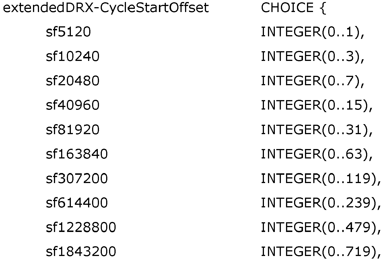
- FIG. 3 illustrating a process 30 according to at least one embodiment of the invention.
- the process 30 is for use in a UE accessing a communication network.
- the UE is configured to use DRX when it is in connected mode with the communication network.
- the extended DRX comprises extended DRX cycles and offsets, which are based on a value of a specific DRX cycle (e.g. 2560ms).
- step S31 signaling from the communication network is received.
- the signaling comprises an extended DRX cycle indication and an offset value.
- step S32 an extended DRX cycle is calculated from the extended DRX cycle indication and an offset is calculated from the offset value, using the value of the specific DRX cycle.
- step S33 DRX is executed when the UE is in the connected mode, with the extended DRX cycle calculated and the offset calculated.
- the value of the specific DRX cycle may be received from the communication network, or may be fixed e.g. to the maximum length of long DRX cycle (e.g. 2560ms).
- the extended DRX cycle indication received in step S31 indicates an extended DRX cycle ("longDRX-Cycle", “eDRX-CycleLength”, as will be explained later on in more detail) and is a first multiplication value of the value of the specific DRX cycle.
- the DRX cycle corresponds to long DRX cycle (e.g. 2560ms).
- the offset value received in step S31 indicates a DRX start offset ("drxStartOffset", as will be explained later on in more detail) and is a second multiplication value of the value of the specific DRX cycle, e.g. long DRX cycle.
- the offset value received in step S31 indicates an extended DRX cycle start offset ("eDRX-CycleStartOffset", as will be explained in more detail later on) and is a second multiplication value of the extended DRX cycle divided by the value of the specific DRX cycle, e.g. long DRX cycle.
- eDRX-CycleStartOffset an extended DRX cycle start offset
- new values are introduced as multiple of the current maximum longDRX-Cycle, i.e. 2560ms. Further, an offset granularity is defined as 2560ms.
- the basis (i.e. value of the specific DRX cycle) for DRX and offset calculation can be signaled instead of being fixed to the 2560ms, as suggested above.
- new values are introduced for extended DRX length as multiple of the current maximum, i.e. 2560ms.
- an offset granularity is defined as the cycle length / 2560 ms, and offset is defined as number of cycle length / 2560 ms.
- the basis i.e. value of specific DRX cycle
- offset calculation can be signaled instead of being fixed to the 2560ms.
- signaling overhead can be minimized without compromising flexibility: enough offset is provided to spread UEs that support extended DRX while legacy UEs can still benefit from 1ms granularity. Further, overlap between legacy UEs and UEs supporting extended DRX can be minimized.
- an extended DRX cycle length up to 60min defined as follows:
- the signaling is:
- the value of longDRX-Cycle is in number of sub-frames.
- Value sf5120 corresponds to 5120 sub-frames
- sf10240 corresponds to 10240 sub-frames and so on. If shortDRX-Cycle is configured, the value of longDRX-Cycle should be a multiple of the shortDRX-Cycle value.
- the value of drxStartOffset value is in number of 2560 sub-frames.
- the signaling is:
- eDRX-CycleLength for extended DRX according to the second embodiment is an extended DRX cycle. Its value is in number of subframes. Value sf5120 corresponds to 5120 sub-frames, sf10240 corresponds to 10240 subframes and so on.
- the value of the above parameter "eDRX-CycleStartOffset" for extended DRX is number of eDRX-CycleLength/2560 subframes. Value 0 corresponds to 0 sub-frames, 1 corresponds to 1 ⁇ eDRX-CycleLength/2560 sub-frames, 2 corresponds to 2* eDRX-CycleLength/2560 subframes and so on.
- a user equipment which may include and/or use the control unit 10 shown in Fig. 2 .
- the user equipment accesses a communication network, using extended discontinuous reception (DRX) when the user equipment is in connected mode with the communication network.
- DRX extended discontinuous reception
- the extended DRX comprises extended DRX cycles and offsets, which are based on a value of a specific DRX cycle.
- the user equipment comprises means for receiving signaling from the communication network, the signaling comprising an extended DRX cycle indication and offset value, means for calculating an extended DRX cycle from the extended DRX cycle indication and an offset from the offset value, using the value of the specific DRX cycle, and means for executing the DRX when the user equipment is in the connected mode with the extended DRX cycle calculated and the offset calculated.
- the means for receiving receive signaling from the communication network, the signaling comprising the value of the specific DRX cycle.
- the value of the specific DRX cycle is the maximum length of long DRX cycle.
- the means for receiving, calculating and executing are implemented by the processing resources 11, memory resources 12 and interfaces 13 of the control unit 10.
- an apparatus of a communication network which may include and/or use the control unit 20 shown in Fig. 2 is provided.
- the apparatus comprises means for signaling an extended DRX cycle indication and offset value to a user equipment accessing the communication network, the user equipment using extended discontinuous reception (DRX) when the user equipment is in connected mode with the communication network, wherein the extended DRX comprises extended DRX cycles and offsets, which are based on a value of a specific DRX cycle.
- DRX extended discontinuous reception
- the means for signaling signal the value of the specific DRX cycle to the user equipment.
- the means for signaling are implemented by the processing resources 21, memory resources 22 and interfaces 23 of the control unit 20.
- the extended DRX cycle indication indicates an extended DRX cycle and is a first multiplication value of the value of the specific DRX cycle.
- the offset value indicates a DRX start offset and is a second multiplication value of the value of the specific DRX cycle.
- the offset value indicates an extended DRX cycle start offset and is a second multiplication value of the extended DRX cycle length divided by the value of the specific DRX cycle.
Landscapes
- Engineering & Computer Science (AREA)
- Computer Networks & Wireless Communication (AREA)
- Signal Processing (AREA)
- Quality & Reliability (AREA)
- Mobile Radio Communication Systems (AREA)
- Small-Scale Networks (AREA)
Abstract
Description
- The present invention relates to extended discontinuous reception (DRX) signaling for connected mode user equipments (UEs).
- The following meanings for the abbreviations used in this specification apply:
- C-RNTI
- Cell Radio Network Temporary Identifier
- DRX
- Discontinuous Reception
- LTE
- Long Term Evolution
- PDCCH
- Physical Downlink Control Channel
- RAN
- Radio Access Network
- RRC
- Radio Resource Control
- SIB
- System Information Block
- UE
- User Equipment
- For UE energy saving purpose, DRX has been defined in LTE. If an UE is configured with DRX by higher layer, the UE is not required to monitor PDCCH when it is not in active time as show in
Fig. 1. Fig. 1 illustrates a DRX cycle in which the UE monitors PDCCH during "On Duration" (active time), and does not monitor PDCCH during "Opportunity for DRX".
- The above parameter "longDRX-CycleStartOffset" comprises longDRX-Cycle and drxStartOffset. The value of longDRX-Cycle is in number of sub-frames. Value sf10 corresponds to 10 sub-frames, sf20 corresponds to 20 sub-frames and so on. If shortDRX-Cycle is configured, the value of longDRX-Cycle should be a multiple of the shortDRX-Cycle value. The value of drxStartOffset value is in number of sub-frames.
- The above parameter "onDurationTimer" is a timer for DRX. Its value is in number of PDCCH sub-frames. Value psf1 corresponds to 1 PDCCH sub-frame, psf2 corresponds to 2 PDCCH sub-frames and so on.
- The above parameter "drx-InactivityTimer" is a timer for DRX. Its value is in number of PDCCH sub-frames. Value psf1 corresponds to 1 PDCCH sub-frame, psf2 corresponds to 2 PDCCH sub-frames and so on.
- The above parameter "drx-RetransmissionTimer" is a timer for DRX. Its value is in number of PDCCH sub-frames. Value psf1 corresponds to 1 PDCCH sub-frame, psf2 corresponds to 2 PDCCH sub-frames and so on.
- The value of the above parameter "shortDRX-Cycle" is in number of sub-frames. Value sf2 corresponds to 2 sub-frames, sf5 corresponds to 5 subframes and so on.
- The above parameter "drxShortCycleTimer" is a timer for DRX. Its value is in multiples of shortDRX-Cycle. A value of 1 corresponds to shortDRX-Cycle, a value of 2 corresponds to 2 * shortDRX-Cycle and so on.
- For power saving purposes, RAN is considering extending connected mode DRX way beyond the current maximum of 2560ms, e.g. to one hour.
- For example, in order to support a DRX cycle of one hour (3600s or 3,600,000ms), a straightforward extension of the current signaling would be to introduce as long DRX-CycleStartOffset parameter the following:

- Clearly, when introducing very large DRX cycles (or extended DRX), a 1ms granularity is not needed to spread the UEs : the number of ms within a cycle is largely superior to the number of UEs that can be supported. For instance, only 65,536 C-RNTI can be allocated (16 bits long), which is to be compared to the 3,600,000 possible offsets in the example of the 1 hour DRX cycle above: ∼100 times more offsets than required.
- According to at least one embodiment of the invention, extended DRX is introduced with minimized signaling overhead and without compromising flexibility.
- According to the present invention, methods, a user equipment, a network apparatus and a computer program product are provided as set out in the appended claims.
- In the following the invention will be described by way of embodiments thereof with reference to the accompanying drawings.
-
-
Fig. 1 shows a diagram illustrating a DRX cycle. -
Fig. 2 shows a schematic block diagram illustrating a configuration of electronic devices in which examples of embodiments of the invention are implementable. -
Fig. 3 shows a flowchart illustrating a process according to an embodiment of the invention. - As a preliminary matter before exploring details of various implementations, reference is made to
Fig. 2 for illustrating a simplified block diagram of acontrol unit 10 and acontrol unit 20 suitable for use in practicing the exemplary embodiments of this invention. - The
control unit 10 may be part of and/or used by a user equipment. Thecontrol unit 10 comprises processing resources (e.g. processing circuitry) 11, memory resources (e.g. memory circuitry) 12 which may store a program, and interfaces (e.g. interface circuitry) 13, which are connected via alink 14. Theinterfaces 13 may comprise a suitable radio frequency (RF) transceiver (not shown) coupled to one or more antennas (not shown) for bidirectional wireless communications over one or more wireless links including asignaling link 15 with thecontrol unit 20. - The
control unit 20 may be part of and/or used by an apparatus of the communication network, e.g. an eNB. Thecontrol unit 20 comprises processing resources (e.g. processing circuitry) 21, memory resources (e.g. memory circuitry) 22 which may store a program, and interfaces (e.g. interface circuitry) 23, which are connected via alink 24. Theinterfaces 23 may comprise a suitable radio frequency (RF) transceiver (not shown) coupled to one or more antennas (not shown) for bidirectional wireless communications over one or more wireless links including thesignaling link 15 with thecontrol unit 10. - The terms "connected," "coupled," or any variant thereof, mean any connection or coupling, either direct or indirect, between two or more elements, and may encompass the presence of one or more intermediate elements between two elements that are "connected" or "coupled" together. The coupling or connection between the elements can be physical, logical, or a combination thereof. As employed herein two elements may be considered to be "connected" or "coupled" together by the use of one or more wires, cables and printed electrical connections, as well as by the use of electromagnetic energy, such as electromagnetic energy having wavelengths in the radio frequency region, the microwave region and the optical (both visible and invisible) region, as non-limiting examples.
- At least one of the programs stored in the
memory resources 11 is assumed to include program instructions that, when executed by the associatedprocessing resources 11, enable the electronic device to operate in accordance with the exemplary embodiments of this invention. Inherent in theprocessing resources 11 is a clock to enable synchronism among the various apparatus for transmissions and receptions within the appropriate time intervals and slots required, as the scheduling grants and the granted resources/subframes are time dependent. The transceivers include both transmitter and receiver, and inherent in each is a modulator/demodulator commonly known as a modem. - In general, the exemplary embodiments of this invention may be implemented by computer software stored in the
memory resources 12 and executable by theprocessing resources 11 of thecontrol unit 10, or by hardware, or by a combination of software and/or firmware and hardware in any or all of the devices shown. - In general, the various embodiments of a UE can include, but are not limited to, mobile stations, cellular telephones, personal digital assistants (PDAs) having wireless communication capabilities, portable computers having wireless communication capabilities, image capture devices such as digital cameras having wireless communication capabilities, gaming devices having wireless communication capabilities, music storage and playback appliances having wireless communication capabilities, Internet appliances permitting wireless Internet access and browsing, as well as portable units or terminals that incorporate combinations of such functions.
- The
memory resources processing resources - Now reference is made to
Fig. 3 illustrating aprocess 30 according to at least one embodiment of the invention. - The
process 30 is for use in a UE accessing a communication network. The UE is configured to use DRX when it is in connected mode with the communication network. The extended DRX comprises extended DRX cycles and offsets, which are based on a value of a specific DRX cycle (e.g. 2560ms). - In step S31, signaling from the communication network is received. The signaling comprises an extended DRX cycle indication and an offset value.
- In step S32, an extended DRX cycle is calculated from the extended DRX cycle indication and an offset is calculated from the offset value, using the value of the specific DRX cycle.
- In step S33, DRX is executed when the UE is in the connected mode, with the extended DRX cycle calculated and the offset calculated.
- The value of the specific DRX cycle may be received from the communication network, or may be fixed e.g. to the maximum length of long DRX cycle (e.g. 2560ms).
- According to first and second embodiments of the invention, the extended DRX cycle indication received in step S31 indicates an extended DRX cycle ("longDRX-Cycle", "eDRX-CycleLength", as will be explained later on in more detail) and is a first multiplication value of the value of the specific DRX cycle. As an example, the DRX cycle corresponds to long DRX cycle (e.g. 2560ms).
- According to the first embodiment, the offset value received in step S31 indicates a DRX start offset ("drxStartOffset", as will be explained later on in more detail) and is a second multiplication value of the value of the specific DRX cycle, e.g. long DRX cycle.
- According to the second embodiment of the invention, the offset value received in step S31 indicates an extended DRX cycle start offset ("eDRX-CycleStartOffset", as will be explained in more detail later on) and is a second multiplication value of the extended DRX cycle divided by the value of the specific DRX cycle, e.g. long DRX cycle.
- In order to configure DRX cycles longer than the current maximum, i.e. extended DRX, according to an implementation example of the first embodiment of the invention, new values are introduced as multiple of the current maximum longDRX-Cycle, i.e. 2560ms. Further, an offset granularity is defined as 2560ms.
- For instance, in order to introduce an extended DRX cycle of ∼90s:
- the DRX cycle (extended DRX cycle indication) is signaled as 35 (35 × 2560ms = 89600ms), and
- the offset value is signaled as 0..34, where a value of 0 means no offset, 1 means an offset of 2560ms, 2 means an offset of 5120ms, and so on.
- Alternatively, the basis (i.e. value of the specific DRX cycle) for DRX and offset calculation can be signaled instead of being fixed to the 2560ms, as suggested above.
- According to an implementation example of the second embodiment, new values are introduced for extended DRX length as multiple of the current maximum, i.e. 2560ms. Further, an offset granularity is defined as the cycle length / 2560 ms, and offset is defined as number of cycle length / 2560 ms.
- For instance, in order to introduce an extended DRX cycle of ∼80s:
- the DRX cycle (extended DRX cycle indication) is signaled as 32 (32 × 2560ms = 81920ms) or 81920 sub-frames, and
- the offset value is signaled as 0..2559, with a granularity of 81920/2560=32ms, where a value of 0 means no offset, 1 means an offset of 32ms, 2 means an offset of 2 × 32ms, and so on.
- As described above for the first and second embodiments, the basis (i.e. value of specific DRX cycle) for DRX and offset calculation can be signaled instead of being fixed to the 2560ms.
- With the proposed introduction of extended DRX according to the first and second embodiments, signaling overhead can be minimized without compromising flexibility: enough offset is provided to spread UEs that support extended DRX while legacy UEs can still benefit from 1ms granularity. Further, overlap between legacy UEs and UEs supporting extended DRX can be minimized.
- Taking as an example an extended DRX cycle length up to 60min defined as follows:
- 5s (5120ms = 2 × 2560)
- 10s (10240ms = 4 × 2560)
- 20s (20480ms = 8 × 2560)
- 40s (40960ms = 16 × 2560)
- 80s (81920ms = 32 × 2560)
- 160s (163840ms = 64 × 2560)
- 5min (307200ms = 120 × 2560)
- 10min (614400ms = 240 × 2560)
- 20min (1228800ms = 480 × 2560)
- 30min (1843200ms = 720 × 2560)
- 40min (2457600ms = 960 × 2560)
- 50min (3072000ms = 1200 × 2560)
- 60min (3686400ms = 1440 × 2560)
- For the first embodiment, the signaling is:
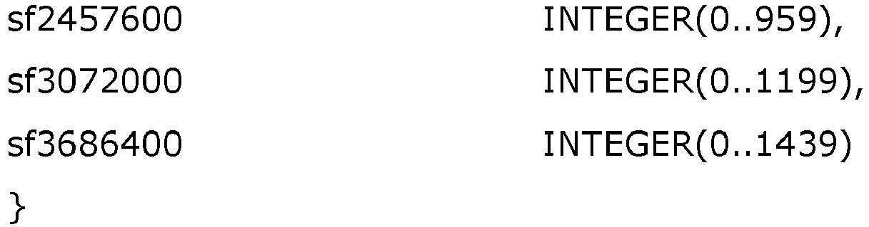
- The above parameter "extendedDRX-CycleStartOffset" for extended DRX according to the first embodiment comprises longDRX-Cycle and drxStartOffset. The value of longDRX-Cycle is in number of sub-frames. Value sf5120 corresponds to 5120 sub-frames, sf10240 corresponds to 10240 sub-frames and so on. If shortDRX-Cycle is configured, the value of longDRX-Cycle should be a multiple of the shortDRX-Cycle value. The value of drxStartOffset value is in number of 2560 sub-frames.
- For the second embodiment, the signaling is:
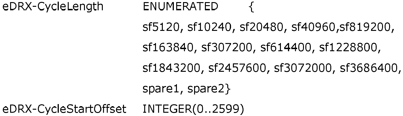
- The above parameter "eDRX-CycleLength" for extended DRX according to the second embodiment is an extended DRX cycle. Its value is in number of subframes. Value sf5120 corresponds to 5120 sub-frames, sf10240 corresponds to 10240 subframes and so on.
- The value of the above parameter "eDRX-CycleStartOffset" for extended DRX according to the second embodiment is number of eDRX-CycleLength/2560 subframes. Value 0 corresponds to 0 sub-frames, 1 corresponds to 1∗eDRX-CycleLength/2560 sub-frames, 2 corresponds to 2* eDRX-CycleLength/2560 subframes and so on.
- When calculating which subframe to wake up, the timing maintained in the UE based on SIB16 can be used with the formulation below:

- According to an aspect of the present invention, a user equipment is provided which may include and/or use the
control unit 10 shown inFig. 2 . The user equipment accesses a communication network, using extended discontinuous reception (DRX) when the user equipment is in connected mode with the communication network. The extended DRX comprises extended DRX cycles and offsets, which are based on a value of a specific DRX cycle. The user equipment comprises means for receiving signaling from the communication network, the signaling comprising an extended DRX cycle indication and offset value, means for calculating an extended DRX cycle from the extended DRX cycle indication and an offset from the offset value, using the value of the specific DRX cycle, and means for executing the DRX when the user equipment is in the connected mode with the extended DRX cycle calculated and the offset calculated. - According to an embodiment of the invention, the means for receiving receive signaling from the communication network, the signaling comprising the value of the specific DRX cycle.
- According to another embodiment of the invention, the value of the specific DRX cycle is the maximum length of long DRX cycle.
- According to an implementation example of the invention, the means for receiving, calculating and executing are implemented by the
processing resources 11,memory resources 12 andinterfaces 13 of thecontrol unit 10. - According to another aspect of the invention, an apparatus of a communication network, which may include and/or use the
control unit 20 shown inFig. 2 is provided. The apparatus comprises means for signaling an extended DRX cycle indication and offset value to a user equipment accessing the communication network, the user equipment using extended discontinuous reception (DRX) when the user equipment is in connected mode with the communication network, wherein the extended DRX comprises extended DRX cycles and offsets, which are based on a value of a specific DRX cycle. - According to an embodiment of the invention, the means for signaling signal the value of the specific DRX cycle to the user equipment.
- According to an implementation example of the invention, the means for signaling are implemented by the
processing resources 21,memory resources 22 andinterfaces 23 of thecontrol unit 20. - In the above aspects, according to an embodiment of the invention, the extended DRX cycle indication indicates an extended DRX cycle and is a first multiplication value of the value of the specific DRX cycle.
- In the above aspects, according to an embodiment of the invention, the offset value indicates a DRX start offset and is a second multiplication value of the value of the specific DRX cycle.
- In the above aspects, according to another embodiment of the invention, the offset value indicates an extended DRX cycle start offset and is a second multiplication value of the extended DRX cycle length divided by the value of the specific DRX cycle.
- It is to be understood that the above description is illustrative of the invention and is not to be construed as limiting the invention. Various modifications and applications may occur to those skilled in the art without departing from the true spirit and scope of the invention as defined by the appended claims.
-
- Clause 1. A method for use in a user equipment accessing a communication network, the user equipment using extended discontinuous reception (DRX) when the user equipment is in connected mode with the communication network, wherein the extended DRX comprises extended DRX cycles and offsets, which are based on a value of a specific DRX cycle, the method comprising:
- receiving signaling from the communication network, the signaling comprising an extended DRX cycle indication and offset value;
- calculating an extended DRX cycle from the extended DRX cycle indication and an offset from the offset value, using the value of the specific DRX cycle; and
- executing the DRX when the user equipment is in the connected mode with the extended DRX cycle calculated and the offset calculated.
- Clause 2. The method of clause 1, comprising:
receiving signaling from the communication network, the signaling comprising the value of the specific DRX cycle. - Clause 3. A method for use in an apparatus of a communication network, the method comprising:
signaling an extended DRX cycle indication and offset value to a user equipment accessing the communication network, the user equipment using extended discontinuous reception (DRX) when the user equipment is in connected mode with the communication network, wherein the extended DRX comprises extended DRX cycles and offsets, which are based on a value of a specific DRX cycle. - Clause 4. The method of clause 3, comprising:
signaling the value of the specific DRX cycle to the user equipment. - Clause 5. The method of clause 1, wherein the value of the specific DRX cycle is the maximum length of long DRX cycle.
- Clause 6. The method of any one of clauses 1 to 5, wherein the extended DRX cycle indication indicates an extended DRX cycle and is a first multiplication value of the value of the specific DRX cycle.
- Clause 7. The method of any one of clauses 1 to 6, wherein the offset value indicates a DRX start offset and is a second multiplication value of the value of the specific DRX cycle.
- Clause 8. The method of any one of clauses 1 to 6, wherein the offset value indicates an extended DRX cycle start offset and is a second multiplication value of the extended DRX cycle length divided by the value of the specific DRX cycle.
- Clause 9. A computer program product including a program for a processing device, comprising software code portions for performing the steps of any one of clauses 1 to 8 when the program is run on the processing device.
-
Clause 10. The computer program product according to clause 9, wherein the computer program product comprises a computer-readable medium on which the software code portions are stored. -
Clause 11. The computer program product according to clause 9, wherein the program is directly loadable into an internal memory of the processing device. -
Clause 12. An apparatus accessing a communication network, the apparatus using extended discontinuous reception (DRX) when the apparatus is in connected mode with the communication network, wherein the extended DRX comprises extended DRX cycles and offsets, which are based on a value of a specific DRX cycle, the apparatus comprising at least one processor and at least one memory including computer program code, the at least one memory and the computer program code configured to, with the at least one processor, cause the apparatus to perform:- receiving signaling from the communication network, the signaling comprising an extended DRX cycle indication and offset value;
- calculating an extended DRX cycle from the extended DRX cycle indication and an offset from the offset value, using the value of the specific DRX cycle; and
- executing the DRX when the user equipment is in the connected mode with the extended DRX cycle calculated and the offset calculated.
-
Clause 13. The apparatus ofclause 12, wherein the at least one memory and the computer program code are configured to, with the at least one processor, cause the apparatus to perform:
receiving signaling from the communication network, the signaling comprising the value of the specific DRX cycle. -
Clause 14. An apparatus of a communication network, the apparatus comprising at least one processor and at least one memory including computer program code, the at least one memory and the computer program code configured to, with the at least one processor, cause the apparatus at least to perform:
signaling an extended DRX cycle indication and offset value to a user equipment accessing the communication network, the user equipment using extended discontinuous reception (DRX) when the user equipment is in connected mode with the communication network, wherein the extended DRX comprises extended DRX cycles and offsets, which are based on a value of a specific DRX cycle. -
Clause 15. The apparatus ofclause 14, wherein the at least one memory and the computer program code are configured to, with the at least one processor, cause the apparatus to perform:
signaling the value of the specific DRX cycle to the user equipment. - Clause 16. The apparatus of
clause 12, wherein the value of the specific DRX cycle is the maximum length of long DRX cycle. - Clause 17. The apparatus of any one of
clauses 12 to 16, wherein the extended DRX cycle indication indicates an extended DRX cycle and is a first multiplication value of the value of the specific DRX cycle. - Clause 18. The apparatus of any one of
clauses 12 to 17, wherein the offset value indicates a DRX start offset and is a second multiplication value of the value of the specific DRX cycle. - Clause 19. The apparatus of any one of
clauses 12 to 17, wherein the offset value indicates an extended DRX cycle start offset and is a second multiplication value of the extended DRX cycle length divided by the value of the specific DRX cycle.
Claims (15)
- A method for use in a user equipment accessing a communication network, the user equipment using extended discontinuous reception (DRX) when the user equipment is in connected mode with the communication network, wherein the extended DRX comprises extended DRX cycles and offsets, which are based on a value of a specific DRX cycle, the method comprising:receiving signaling from the communication network, the signaling comprising an extended DRX cycle indication and offset value;calculating an extended DRX cycle from the extended DRX cycle indication and an offset from the offset value, using the value of the specific DRX cycle; andexecuting the DRX when the user equipment is in the connected mode with the extended DRX cycle calculated and the offset calculated.
- The method of claim 1, comprising:
receiving signaling from the communication network, the signaling comprising the value of the specific DRX cycle. - A method for use in an apparatus of a communication network, the method comprising:
signaling an extended DRX cycle indication and offset value to a user equipment accessing the communication network, the user equipment using extended discontinuous reception (DRX) when the user equipment is in connected mode with the communication network, wherein the extended DRX comprises extended DRX cycles and offsets, which are based on a value of a specific DRX cycle. - The method of claim 3, comprising:
signaling the value of the specific DRX cycle to the user equipment. - The method of any of claims 1 to 4, wherein the value of the specific DRX cycle is the maximum length of long DRX cycle.
- The method of any one of claims 1 to 5, wherein the extended DRX cycle indication indicates an extended DRX cycle and is a first multiplication value of the value of the specific DRX cycle.
- The method of any one of claims 1 to 6, wherein the offset value indicates a DRX start offset and is a second multiplication value of the value of the specific DRX cycle.
- The method of any one of claims 1 to 6, wherein the offset value indicates an extended DRX cycle start offset and is a second multiplication value of the extended DRX cycle length divided by the value of the specific DRX cycle.
- A computer program product including a program for a processing device, comprising software code portions for performing the steps of any one of claims 1 to 8 when the program is run on the processing device.
- An apparatus accessing a communication network, the apparatus using extended discontinuous reception (DRX) when the apparatus is in connected mode with the communication network, wherein the extended DRX comprises extended DRX cycles and offsets, which are based on a value of a specific DRX cycle, the apparatus comprising means for:receiving signaling from the communication network, the signaling comprising an extended DRX cycle indication and offset value;calculating an extended DRX cycle from the extended DRX cycle indication and an offset from the offset value, using the value of the specific DRX cycle; andexecuting the DRX when the user equipment is in the connected mode with the extended DRX cycle calculated and the offset calculated.
- The apparatus of claim 10, further comprising means for:
receiving signaling from the communication network, the signaling comprising the value of the specific DRX cycle. - An apparatus of a communication network, the apparatus comprising means for:
signaling an extended DRX cycle indication and offset value to a user equipment accessing the communication network, the user equipment using extended discontinuous reception (DRX) when the user equipment is in connected mode with the communication network, wherein the extended DRX comprises extended DRX cycles and offsets, which are based on a value of a specific DRX cycle. - The apparatus of claim 12, further comprising means for:
signaling the value of the specific DRX cycle to the user equipment. - The apparatus of any of claims 10 to 13, wherein the value of the specific DRX cycle is the maximum length of long DRX cycle.
- The apparatus of any one of claims 10 to 14, wherein the extended DRX cycle indication indicates an extended DRX cycle and is a first multiplication value of the value of the specific DRX cycle.
Priority Applications (3)
| Application Number | Priority Date | Filing Date | Title |
|---|---|---|---|
| ES21153484T ES2971676T3 (en) | 2015-03-11 | 2015-03-11 | Extended discontinuous reception signaling for user equipment in connected mode |
| EP21153484.7A EP3876598B1 (en) | 2015-03-11 | 2015-03-11 | Extended discontinous reception signaling for connected mode user equipments |
| PL21153484.7T PL3876598T3 (en) | 2015-03-11 | 2015-03-11 | Extended discontinous reception signaling for connected mode user equipments |
Applications Claiming Priority (3)
| Application Number | Priority Date | Filing Date | Title |
|---|---|---|---|
| EP15884243.5A EP3269175B1 (en) | 2015-03-11 | 2015-03-11 | Extended discontinuous reception signaling for connected mode user equipments |
| EP21153484.7A EP3876598B1 (en) | 2015-03-11 | 2015-03-11 | Extended discontinous reception signaling for connected mode user equipments |
| PCT/CN2015/073979 WO2016141560A1 (en) | 2015-03-11 | 2015-03-11 | Extended discontinuous reception signaling for connected mode user equipments |
Related Parent Applications (1)
| Application Number | Title | Priority Date | Filing Date |
|---|---|---|---|
| EP15884243.5A Division EP3269175B1 (en) | 2015-03-11 | 2015-03-11 | Extended discontinuous reception signaling for connected mode user equipments |
Publications (3)
| Publication Number | Publication Date |
|---|---|
| EP3876598A1 true EP3876598A1 (en) | 2021-09-08 |
| EP3876598B1 EP3876598B1 (en) | 2023-12-27 |
| EP3876598C0 EP3876598C0 (en) | 2023-12-27 |
Family
ID=56878734
Family Applications (2)
| Application Number | Title | Priority Date | Filing Date |
|---|---|---|---|
| EP15884243.5A Active EP3269175B1 (en) | 2015-03-11 | 2015-03-11 | Extended discontinuous reception signaling for connected mode user equipments |
| EP21153484.7A Active EP3876598B1 (en) | 2015-03-11 | 2015-03-11 | Extended discontinous reception signaling for connected mode user equipments |
Family Applications Before (1)
| Application Number | Title | Priority Date | Filing Date |
|---|---|---|---|
| EP15884243.5A Active EP3269175B1 (en) | 2015-03-11 | 2015-03-11 | Extended discontinuous reception signaling for connected mode user equipments |
Country Status (10)
| Country | Link |
|---|---|
| US (1) | US10225881B2 (en) |
| EP (2) | EP3269175B1 (en) |
| JP (1) | JP6538868B2 (en) |
| CN (1) | CN107409330B (en) |
| ES (2) | ES2856853T3 (en) |
| PH (1) | PH12017501597B1 (en) |
| PL (2) | PL3269175T3 (en) |
| RU (1) | RU2680745C1 (en) |
| TW (1) | TWI692985B (en) |
| WO (1) | WO2016141560A1 (en) |
Families Citing this family (6)
| Publication number | Priority date | Publication date | Assignee | Title |
|---|---|---|---|---|
| WO2017009053A1 (en) * | 2015-07-16 | 2017-01-19 | Sony Corporation | Communications terminal, infrastructure equipment and methods for discontinuous reception, drx |
| US11546964B2 (en) * | 2017-05-04 | 2023-01-03 | Guangdong Oppo Mobile Telecommunications Corp., Ltd. | Method and device for discontinuous reception |
| MX2020002631A (en) * | 2017-09-07 | 2020-07-20 | Guangdong Oppo Mobile Telecommunications Corp Ltd | Discontinuous reception method, terminal device and network device. |
| AU2018436780B2 (en) | 2018-11-02 | 2022-12-22 | Zte Corporation | Adaptive parameter configuration in wireless communication |
| CN114080067B (en) | 2020-08-20 | 2024-03-19 | 维沃移动通信有限公司 | Discontinuous reception DRX configuration method, device and equipment |
| US20240373505A1 (en) * | 2021-06-25 | 2024-11-07 | Telefonaktiebolaget Lm Ericsson (Publ) | Alignment of DRX Cycles for Downlink Communication and D2D Communication |
Citations (1)
| Publication number | Priority date | Publication date | Assignee | Title |
|---|---|---|---|---|
| WO2014158268A1 (en) * | 2013-03-29 | 2014-10-02 | Intel IP Corporation | Extended paging discontinuous reception (drx) cycles in wireless communication networks |
Family Cites Families (20)
| Publication number | Priority date | Publication date | Assignee | Title |
|---|---|---|---|---|
| US7016771B2 (en) | 2004-05-03 | 2006-03-21 | General Motors Corporation | Method and system for flexible discontinuous receive management in a telematics system |
| CN100579275C (en) * | 2006-07-19 | 2010-01-06 | 展讯通信(上海)有限公司 | A method for negotiating DRX cycle in mobile communication system |
| EP2566237B1 (en) | 2007-02-05 | 2014-08-20 | Nec Corporation | Inter base station handover methods, base station, and communication terminal |
| EP3557917B1 (en) * | 2007-02-06 | 2020-05-13 | Nokia Technologies Oy | Method and apparatus for providing efficient discontinuous communication |
| US8023467B2 (en) * | 2007-04-27 | 2011-09-20 | Research In Motion Limited | Method and system for efficient DRX operation during handover in LTE |
| AU2007353893B2 (en) * | 2007-05-23 | 2011-01-27 | Telefonaktiebolaget Lm Ericsson (Publ) | Method and arrangement for reducing battery power consumption of a user equipment |
| US8804546B2 (en) | 2008-06-13 | 2014-08-12 | Qualcomm Incorporated | Method and apparatus for managing interaction between DRX cycles and paging cycles |
| EP2205029A1 (en) | 2009-01-06 | 2010-07-07 | Thomson Licensing | A method for scheduling wake/sleep cycles by a central device in a wireless network |
| US8837313B2 (en) | 2011-04-04 | 2014-09-16 | Kyocera Corporation | Mobile communication method and radio terminal |
| WO2013062325A1 (en) * | 2011-10-26 | 2013-05-02 | Lg Electronics Inc. | Method and apparatus for updating extended access barring information |
| JP2013197988A (en) * | 2012-03-21 | 2013-09-30 | Advantest Corp | Radio communication device and radio communication system |
| US10111168B2 (en) | 2012-05-02 | 2018-10-23 | Mediatek Inc. | User equipment enhancement for diverse data application |
| CN104105111B (en) * | 2013-04-02 | 2017-11-21 | 电信科学技术研究院 | The computational methods and device of a kind of activation moments |
| WO2014163573A1 (en) * | 2013-04-05 | 2014-10-09 | Telefonaktiebolaget L M Ericsson (Publ) | User equipment, network node, and methods for managing an extended discontinuous reception cycle mode |
| WO2014175003A1 (en) | 2013-04-26 | 2014-10-30 | シャープ株式会社 | Terminal apparatus, integrated circuit, and radio communication method |
| CN104125612B (en) | 2013-04-28 | 2019-09-24 | 中兴通讯股份有限公司 | Discontinuous reception cycle synchronization method, system and device |
| JP5627808B2 (en) | 2014-02-06 | 2014-11-19 | 京セラ株式会社 | Wireless terminal and apparatus |
| US9763172B2 (en) * | 2014-08-06 | 2017-09-12 | Qualcomm Incorporated | Idle-mode enhancements for extended idle discontinuous reception (EI-DRX) |
| US10440661B2 (en) * | 2014-08-06 | 2019-10-08 | Quacomm Incorporated | RAN procedures for extended discontinuous reception (DRX) |
| US10085300B2 (en) * | 2015-02-16 | 2018-09-25 | Qualcomm Incorporated | Connected mode extended discontinuous reception |
-
2015
- 2015-03-11 US US15/549,610 patent/US10225881B2/en active Active
- 2015-03-11 EP EP15884243.5A patent/EP3269175B1/en active Active
- 2015-03-11 JP JP2017547415A patent/JP6538868B2/en active Active
- 2015-03-11 ES ES15884243T patent/ES2856853T3/en active Active
- 2015-03-11 PL PL15884243T patent/PL3269175T3/en unknown
- 2015-03-11 PL PL21153484.7T patent/PL3876598T3/en unknown
- 2015-03-11 RU RU2017133528A patent/RU2680745C1/en active
- 2015-03-11 WO PCT/CN2015/073979 patent/WO2016141560A1/en not_active Ceased
- 2015-03-11 CN CN201580077662.1A patent/CN107409330B/en active Active
- 2015-03-11 EP EP21153484.7A patent/EP3876598B1/en active Active
- 2015-03-11 ES ES21153484T patent/ES2971676T3/en active Active
-
2016
- 2016-02-18 TW TW105104690A patent/TWI692985B/en active
-
2017
- 2017-09-05 PH PH12017501597A patent/PH12017501597B1/en unknown
Patent Citations (1)
| Publication number | Priority date | Publication date | Assignee | Title |
|---|---|---|---|---|
| WO2014158268A1 (en) * | 2013-03-29 | 2014-10-02 | Intel IP Corporation | Extended paging discontinuous reception (drx) cycles in wireless communication networks |
Non-Patent Citations (1)
| Title |
|---|
| CATT: "Discussion on DRX Offset configuration", 3GPP DRAFT; R2-085323, 3RD GENERATION PARTNERSHIP PROJECT (3GPP), MOBILE COMPETENCE CENTRE ; 650, ROUTE DES LUCIOLES ; F-06921 SOPHIA-ANTIPOLIS CEDEX ; FRANCE, no. Prague, Czech Republic; 20080923, 23 September 2008 (2008-09-23), XP050320187 * |
Also Published As
| Publication number | Publication date |
|---|---|
| RU2680745C1 (en) | 2019-02-26 |
| ES2856853T3 (en) | 2021-09-28 |
| JP6538868B2 (en) | 2019-07-03 |
| EP3269175A1 (en) | 2018-01-17 |
| PH12017501597B1 (en) | 2021-07-07 |
| US10225881B2 (en) | 2019-03-05 |
| EP3876598B1 (en) | 2023-12-27 |
| CN107409330A (en) | 2017-11-28 |
| EP3876598C0 (en) | 2023-12-27 |
| PL3269175T3 (en) | 2021-05-31 |
| PL3876598T3 (en) | 2024-07-01 |
| US20180042068A1 (en) | 2018-02-08 |
| EP3269175B1 (en) | 2021-01-27 |
| CN107409330B (en) | 2021-02-19 |
| JP2018511992A (en) | 2018-04-26 |
| WO2016141560A1 (en) | 2016-09-15 |
| EP3269175A4 (en) | 2018-10-03 |
| TW201637479A (en) | 2016-10-16 |
| PH12017501597A1 (en) | 2018-02-12 |
| TWI692985B (en) | 2020-05-01 |
| ES2971676T3 (en) | 2024-06-06 |
Similar Documents
| Publication | Publication Date | Title |
|---|---|---|
| CN105122858B (en) | Handling downlink semi-persistent scheduling retransmissions in wireless networks | |
| CN110912663B (en) | A communication method and device | |
| EP3354088B1 (en) | Pf/po calculations and use thereof for edrx | |
| EP3269175B1 (en) | Extended discontinuous reception signaling for connected mode user equipments | |
| CN111565443B (en) | Method for determining discontinuous reception activation state and terminal | |
| WO2020221879A1 (en) | Determining pdcch monitoring during on-duration when in power saving mode | |
| US12395929B2 (en) | Reception scheme | |
| EP2826166A1 (en) | Techniques for timers associated with powering receiver circuitry at a wireless device | |
| CN109804685A (en) | It is handled using the activationary time of two step authorizations | |
| WO2013114157A1 (en) | Method and apparatus for preserving physical uplink control channel resources | |
| CN114073132A (en) | Wake-up signal monitoring indication | |
| US20180176982A1 (en) | Method, terminal and system for reducing power consumption of cluster terminal in broadband cluster system | |
| CN116234042A (en) | A communication method and device | |
| WO2014110802A1 (en) | Tdd configuration change for uplink-downlink interference management and traffic adaptation | |
| HK1244146B (en) | Extended discontinuous reception signaling for connected mode user equipments | |
| RU2786001C1 (en) | Wake-up signal monitoring indication | |
| CN121195564A (en) | Low-power wake-up signal paging | |
| CN120380811A (en) | Paging scheme in multi-cell camping | |
| CN117835400A (en) | Configuration determination method, configuration method, device, terminal and network side equipment | |
| CN116996974A (en) | Information transmission methods, devices and communication equipment |
Legal Events
| Date | Code | Title | Description |
|---|---|---|---|
| PUAI | Public reference made under article 153(3) epc to a published international application that has entered the european phase |
Free format text: ORIGINAL CODE: 0009012 |
|
| STAA | Information on the status of an ep patent application or granted ep patent |
Free format text: STATUS: THE APPLICATION HAS BEEN PUBLISHED |
|
| AC | Divisional application: reference to earlier application |
Ref document number: 3269175 Country of ref document: EP Kind code of ref document: P |
|
| AK | Designated contracting states |
Kind code of ref document: A1 Designated state(s): AL AT BE BG CH CY CZ DE DK EE ES FI FR GB GR HR HU IE IS IT LI LT LU LV MC MK MT NL NO PL PT RO RS SE SI SK SM TR |
|
| STAA | Information on the status of an ep patent application or granted ep patent |
Free format text: STATUS: REQUEST FOR EXAMINATION WAS MADE |
|
| 17P | Request for examination filed |
Effective date: 20220308 |
|
| RBV | Designated contracting states (corrected) |
Designated state(s): AL AT BE BG CH CY CZ DE DK EE ES FI FR GB GR HR HU IE IS IT LI LT LU LV MC MK MT NL NO PL PT RO RS SE SI SK SM TR |
|
| GRAP | Despatch of communication of intention to grant a patent |
Free format text: ORIGINAL CODE: EPIDOSNIGR1 |
|
| STAA | Information on the status of an ep patent application or granted ep patent |
Free format text: STATUS: GRANT OF PATENT IS INTENDED |
|
| INTG | Intention to grant announced |
Effective date: 20230523 |
|
| GRAJ | Information related to disapproval of communication of intention to grant by the applicant or resumption of examination proceedings by the epo deleted |
Free format text: ORIGINAL CODE: EPIDOSDIGR1 |
|
| STAA | Information on the status of an ep patent application or granted ep patent |
Free format text: STATUS: REQUEST FOR EXAMINATION WAS MADE |
|
| GRAS | Grant fee paid |
Free format text: ORIGINAL CODE: EPIDOSNIGR3 |
|
| STAA | Information on the status of an ep patent application or granted ep patent |
Free format text: STATUS: GRANT OF PATENT IS INTENDED |
|
| GRAP | Despatch of communication of intention to grant a patent |
Free format text: ORIGINAL CODE: EPIDOSNIGR1 |
|
| INTC | Intention to grant announced (deleted) | ||
| INTG | Intention to grant announced |
Effective date: 20231005 |
|
| GRAA | (expected) grant |
Free format text: ORIGINAL CODE: 0009210 |
|
| STAA | Information on the status of an ep patent application or granted ep patent |
Free format text: STATUS: THE PATENT HAS BEEN GRANTED |
|
| AC | Divisional application: reference to earlier application |
Ref document number: 3269175 Country of ref document: EP Kind code of ref document: P |
|
| AK | Designated contracting states |
Kind code of ref document: B1 Designated state(s): AL AT BE BG CH CY CZ DE DK EE ES FI FR GB GR HR HU IE IS IT LI LT LU LV MC MK MT NL NO PL PT RO RS SE SI SK SM TR |
|
| REG | Reference to a national code |
Ref country code: GB Ref legal event code: FG4D |
|
| REG | Reference to a national code |
Ref country code: CH Ref legal event code: EP |
|
| REG | Reference to a national code |
Ref country code: DE Ref legal event code: R096 Ref document number: 602015087124 Country of ref document: DE |
|
| REG | Reference to a national code |
Ref country code: IE Ref legal event code: FG4D |
|
| U01 | Request for unitary effect filed |
Effective date: 20240108 |
|
| U07 | Unitary effect registered |
Designated state(s): AT BE BG DE DK EE FI FR IT LT LU LV MT NL PT SE SI Effective date: 20240117 |
|
| U20 | Renewal fee for the european patent with unitary effect paid |
Year of fee payment: 10 Effective date: 20240207 |
|
| REG | Reference to a national code |
Ref country code: GR Ref legal event code: EP Ref document number: 20240400425 Country of ref document: GR Effective date: 20240312 |
|
| PG25 | Lapsed in a contracting state [announced via postgrant information from national office to epo] |
Ref country code: RS Free format text: LAPSE BECAUSE OF FAILURE TO SUBMIT A TRANSLATION OF THE DESCRIPTION OR TO PAY THE FEE WITHIN THE PRESCRIBED TIME-LIMIT Effective date: 20231227 Ref country code: NO Free format text: LAPSE BECAUSE OF FAILURE TO SUBMIT A TRANSLATION OF THE DESCRIPTION OR TO PAY THE FEE WITHIN THE PRESCRIBED TIME-LIMIT Effective date: 20240327 Ref country code: HR Free format text: LAPSE BECAUSE OF FAILURE TO SUBMIT A TRANSLATION OF THE DESCRIPTION OR TO PAY THE FEE WITHIN THE PRESCRIBED TIME-LIMIT Effective date: 20231227 |
|
| REG | Reference to a national code |
Ref country code: ES Ref legal event code: FG2A Ref document number: 2971676 Country of ref document: ES Kind code of ref document: T3 Effective date: 20240606 |
|
| PG25 | Lapsed in a contracting state [announced via postgrant information from national office to epo] |
Ref country code: IS Free format text: LAPSE BECAUSE OF FAILURE TO SUBMIT A TRANSLATION OF THE DESCRIPTION OR TO PAY THE FEE WITHIN THE PRESCRIBED TIME-LIMIT Effective date: 20240427 |
|
| PG25 | Lapsed in a contracting state [announced via postgrant information from national office to epo] |
Ref country code: SK Free format text: LAPSE BECAUSE OF FAILURE TO SUBMIT A TRANSLATION OF THE DESCRIPTION OR TO PAY THE FEE WITHIN THE PRESCRIBED TIME-LIMIT Effective date: 20231227 |
|
| PG25 | Lapsed in a contracting state [announced via postgrant information from national office to epo] |
Ref country code: SM Free format text: LAPSE BECAUSE OF FAILURE TO SUBMIT A TRANSLATION OF THE DESCRIPTION OR TO PAY THE FEE WITHIN THE PRESCRIBED TIME-LIMIT Effective date: 20231227 Ref country code: SK Free format text: LAPSE BECAUSE OF FAILURE TO SUBMIT A TRANSLATION OF THE DESCRIPTION OR TO PAY THE FEE WITHIN THE PRESCRIBED TIME-LIMIT Effective date: 20231227 Ref country code: RO Free format text: LAPSE BECAUSE OF FAILURE TO SUBMIT A TRANSLATION OF THE DESCRIPTION OR TO PAY THE FEE WITHIN THE PRESCRIBED TIME-LIMIT Effective date: 20231227 Ref country code: IS Free format text: LAPSE BECAUSE OF FAILURE TO SUBMIT A TRANSLATION OF THE DESCRIPTION OR TO PAY THE FEE WITHIN THE PRESCRIBED TIME-LIMIT Effective date: 20240427 |
|
| REG | Reference to a national code |
Ref country code: DE Ref legal event code: R097 Ref document number: 602015087124 Country of ref document: DE |
|
| REG | Reference to a national code |
Ref country code: CH Ref legal event code: PL |
|
| PLBE | No opposition filed within time limit |
Free format text: ORIGINAL CODE: 0009261 |
|
| STAA | Information on the status of an ep patent application or granted ep patent |
Free format text: STATUS: NO OPPOSITION FILED WITHIN TIME LIMIT |
|
| PG25 | Lapsed in a contracting state [announced via postgrant information from national office to epo] |
Ref country code: MC Free format text: LAPSE BECAUSE OF FAILURE TO SUBMIT A TRANSLATION OF THE DESCRIPTION OR TO PAY THE FEE WITHIN THE PRESCRIBED TIME-LIMIT Effective date: 20231227 |
|
| PG25 | Lapsed in a contracting state [announced via postgrant information from national office to epo] |
Ref country code: MC Free format text: LAPSE BECAUSE OF FAILURE TO SUBMIT A TRANSLATION OF THE DESCRIPTION OR TO PAY THE FEE WITHIN THE PRESCRIBED TIME-LIMIT Effective date: 20231227 |
|
| 26N | No opposition filed |
Effective date: 20240930 |
|
| PG25 | Lapsed in a contracting state [announced via postgrant information from national office to epo] |
Ref country code: IE Free format text: LAPSE BECAUSE OF NON-PAYMENT OF DUE FEES Effective date: 20240311 |
|
| PG25 | Lapsed in a contracting state [announced via postgrant information from national office to epo] |
Ref country code: IE Free format text: LAPSE BECAUSE OF NON-PAYMENT OF DUE FEES Effective date: 20240311 Ref country code: CH Free format text: LAPSE BECAUSE OF NON-PAYMENT OF DUE FEES Effective date: 20240331 |
|
| U20 | Renewal fee for the european patent with unitary effect paid |
Year of fee payment: 11 Effective date: 20250205 |
|
| PGFP | Annual fee paid to national office [announced via postgrant information from national office to epo] |
Ref country code: ES Payment date: 20250411 Year of fee payment: 11 |
|
| PG25 | Lapsed in a contracting state [announced via postgrant information from national office to epo] |
Ref country code: CY Free format text: LAPSE BECAUSE OF FAILURE TO SUBMIT A TRANSLATION OF THE DESCRIPTION OR TO PAY THE FEE WITHIN THE PRESCRIBED TIME-LIMIT; INVALID AB INITIO Effective date: 20150311 |
|
| PG25 | Lapsed in a contracting state [announced via postgrant information from national office to epo] |
Ref country code: HU Free format text: LAPSE BECAUSE OF FAILURE TO SUBMIT A TRANSLATION OF THE DESCRIPTION OR TO PAY THE FEE WITHIN THE PRESCRIBED TIME-LIMIT; INVALID AB INITIO Effective date: 20150311 |
|
| U20 | Renewal fee for the european patent with unitary effect paid |
Year of fee payment: 12 Effective date: 20260209 |
|
| PGFP | Annual fee paid to national office [announced via postgrant information from national office to epo] |
Ref country code: GB Payment date: 20260202 Year of fee payment: 12 |
|
| PGFP | Annual fee paid to national office [announced via postgrant information from national office to epo] |
Ref country code: TR Payment date: 20260309 Year of fee payment: 12 |
|
| PGFP | Annual fee paid to national office [announced via postgrant information from national office to epo] |
Ref country code: CZ Payment date: 20260219 Year of fee payment: 12 |
|
| PGFP | Annual fee paid to national office [announced via postgrant information from national office to epo] |
Ref country code: PL Payment date: 20260206 Year of fee payment: 12 Ref country code: GR Payment date: 20260211 Year of fee payment: 12 |