EP3876437A1 - System and method for calibrating antenna array - Google Patents
System and method for calibrating antenna array Download PDFInfo
- Publication number
- EP3876437A1 EP3876437A1 EP21161321.1A EP21161321A EP3876437A1 EP 3876437 A1 EP3876437 A1 EP 3876437A1 EP 21161321 A EP21161321 A EP 21161321A EP 3876437 A1 EP3876437 A1 EP 3876437A1
- Authority
- EP
- European Patent Office
- Prior art keywords
- matrix
- equals
- elements
- antenna
- radiating elements
- Prior art date
- Legal status (The legal status is an assumption and is not a legal conclusion. Google has not performed a legal analysis and makes no representation as to the accuracy of the status listed.)
- Granted
Links
Images





Classifications
-
- H—ELECTRICITY
- H04—ELECTRIC COMMUNICATION TECHNIQUE
- H04B—TRANSMISSION
- H04B17/00—Monitoring; Testing
- H04B17/10—Monitoring; Testing of transmitters
- H04B17/11—Monitoring; Testing of transmitters for calibration
- H04B17/12—Monitoring; Testing of transmitters for calibration of transmit antennas, e.g. of the amplitude or phase
-
- H—ELECTRICITY
- H04—ELECTRIC COMMUNICATION TECHNIQUE
- H04B—TRANSMISSION
- H04B17/00—Monitoring; Testing
- H04B17/10—Monitoring; Testing of transmitters
- H04B17/101—Monitoring; Testing of transmitters for measurement of specific parameters of the transmitter or components thereof
- H04B17/102—Power radiated at antenna
-
- G—PHYSICS
- G01—MEASURING; TESTING
- G01R—MEASURING ELECTRIC VARIABLES; MEASURING MAGNETIC VARIABLES
- G01R29/00—Arrangements for measuring or indicating electric quantities not covered by groups G01R19/00 - G01R27/00
- G01R29/08—Measuring electromagnetic field characteristics
- G01R29/10—Radiation diagrams of antennas
Definitions
- Antenna technology is rapidly progressing in the area of antenna arrays (e.g., active phased array antennas, commonly referred to as electronically steered antennas (ESAs)), that employ either digital or analog beamforming technologies to control the gain and phase settings of individual antenna elements (e.g., radiating elements) in order to electronically steer the resulting beam.
- antenna arrays e.g., active phased array antennas, commonly referred to as electronically steered antennas (ESAs)
- ESAs electronically steered antennas
- This physical arrangement of many small beam forming devices in a single system allows for functionality that previously required larger passive (e.g., slotted waveguide) antennas, accompanied by mechanical hardware, to physically point the antenna at a target location.
- passive e.g., slotted waveguide
- this technology also improves control over directionality, which leads to improvement in Low Probability of Intercept (LPI) and Low Probability of Detection (LPD).
- LPI Low Probability of Intercept
- LPD Low Probability of Detection
- NF Near Field
- FF Far Field
- inventions of the inventive concepts disclosed herein are directed to a system.
- the system may include an antenna array including antenna radiating elements.
- the system may further include a processor communicatively coupled to the antenna array.
- the processor may be configured to: use a generalized form of Hadamard Codes to perform measurements of the antenna radiating elements, the generalized form of Hadamard Codes including amplitude coefficients and phase coefficients for the antenna radiating elements; receive a first set of measurements of the antenna radiating elements as a first measurement coding matrix; receive a second set of measurements of the antenna radiating elements as a second measurement coding matrix; receive a third set of measurements of the antenna radiating elements as a third measurement coding matrix, wherein the third measurement coding matrix corresponds to all of the antenna radiating elements being in a powered on state; receive a fourth set of measurements of the antenna radiating elements as a fourth measurement coding matrix, wherein the fourth measurement coding matrix corresponds to all of the antenna radiating elements being in a powered down state; calculate a reference
- inventions of the inventive concepts disclosed herein are directed to a method.
- the method may include: using, by at least one processor communicatively coupled to an antenna array comprising antenna radiating elements, a generalized form of Hadamard Codes to perform measurements of the antenna radiating elements, the generalized form of Hadamard Codes including amplitude coefficients and phase coefficients for the antenna radiating elements; receiving, by the at least one processor, a first set of measurements of the antenna radiating elements as a first measurement coding matrix; receiving, by the at least one processor, a second set of measurements of the antenna radiating elements as a second measurement coding matrix; receiving, by the at least one processor, a third set of measurements of the antenna radiating elements as a third measurement coding matrix, wherein the third measurement coding matrix corresponds to all of the antenna radiating elements being in a powered on state; receiving, by the at least one processor, a fourth set of measurements of the antenna radiating elements as a fourth measurement coding matrix, wherein the fourth measurement coding matrix corresponds to
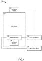
- FIG. 1 is a view of an exemplary embodiment of a system according to the inventive concepts disclosed herein.
- FIG. 2 is an exemplary test equipment of the system of FIG. 1 according to the inventive concepts disclosed herein.
- FIG. 3 is an exemplary computing device of the system of FIG. 1 according to the inventive concepts disclosed herein.
- FIGS. 4A and 4B show an exemplary antenna array of the system of FIG. 1 according to the inventive concepts disclosed herein.
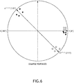
- FIGS. 5 and 6 illustrate writing phase offset values into two quadrants of a phase circle so as to provide both positive and negative vector components according to the inventive concepts disclosed herein.
- FIGS. 7A , 7B , 7C , 7D show equations, which may be used in an exemplary embodiment of testing and/or calibrating an exemplary antenna array, according to the inventive concepts disclosed herein.
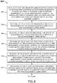
- FIG. 8 is a diagram of an exemplary embodiment of a method according to the inventive concepts disclosed herein.
- inventive concepts are not limited in their application to the details of construction and the arrangement of the components or steps or methodologies set forth in the following description or illustrated in the drawings.
- inventive concepts disclosed herein may be practiced without these specific details.
- well-known features may not be described in detail to avoid unnecessarily complicating the instant disclosure.
- inventive concepts disclosed herein are capable of other embodiments or of being practiced or carried out in various ways. Also, it is to be understood that the phraseology and terminology employed herein is for the purpose of description and should not be regarded as limiting.
- a letter following a reference numeral is intended to reference an embodiment of the feature or element that may be similar, but not necessarily identical, to a previously described element or feature bearing the same reference numeral (e.g., 1, 1a, 1b).
- reference numeral e.g. 1, 1a, 1b
- Such shorthand notations are used for purposes of convenience only, and should not be construed to limit the inventive concepts disclosed herein in any way unless expressly stated to the contrary.
- any reference to "one embodiment,” or “some embodiments” means that a particular element, feature, structure, or characteristic described in connection with the embodiment is included in at least one embodiment of the inventive concepts disclosed herein.
- the appearances of the phrase “in some embodiments” in various places in the specification are not necessarily all referring to the same embodiment, and embodiments of the inventive concepts disclosed may include one or more of the features expressly described or inherently present herein, or any combination or sub-combination of two or more such features, along with any other features which may not necessarily be expressly described or inherently present in the instant disclosure.
- embodiments of the inventive concepts disclosed herein are directed to a method and a system configured to test and/or calibrate an antenna array (e.g., an active phased array antenna, commonly referred to as an ESA).
- an antenna array e.g., an active phased array antenna, commonly referred to as an ESA.
- Some embodiments may include an automated calibration solution for calibrating and/or recalibrating ESA antennas.
- Some embodiments may use the techniques described herein in a manual fashion.
- Various environmental conditions, operating location, and desired changes to operating frequencies may drive a customer need for a convenient solution to quickly calibrate an ESA antenna.
- Some embodiments disclosed herein may be implemented as a software package executed by a processor causing the calibration solution to be performed.
- the system 100 may be implemented as any suitable system.
- the system 100 may include at least one antenna probe 102, at least one enclosure 104, at least one antenna array 106, at least one antenna mount 108, at least one computing device 110, and/or at least one test equipment 112, some or all of which may be communicatively coupled at any given time.
- Some embodiments may include at least one processor (e.g., at least one processor 202 and/or at least one processor 302) computing gain and phase offset values for each individual antenna radiating element 402 of an antenna array 106 (e.g., a phased array antenna). These gain and phase offset values may be used as a calibration factors (e.g., calibration coefficients) by system firmware (e.g., maintained in a non-transitory computer-readable medium, such as memory 204 and/or 304) to account for manufacturing tolerances and behavioral changes across frequency and temperature, enabling the system and/or antenna array 106 to achieve optimum performance.
- system firmware e.g., maintained in a non-transitory computer-readable medium, such as memory 204 and/or 304 to account for manufacturing tolerances and behavioral changes across frequency and temperature, enabling the system and/or antenna array 106 to achieve optimum performance.
- an uncalibrated antenna array 106 may be placed in an enclosure 104 (e.g., an exceptionally small anechoic chamber enclosure) fixture on a stationary antenna mount 108.
- the antenna array 106 may be orthogonally aligned to a stationary antenna probe 102.
- Test equipment 112 may provide power to the antenna array 106, source vector measurement stimulus signals, and capture composite vector measurement responses.
- the computing device 110 may communicate with the antenna array 106 to set the individual radiating elements 402 to coding patterns (e.g., various sets of reference and encoding states) as defined in the equations herein (e.g., as shown in FIGS. 7A , 7B , 7C , and 7D ).
- the computing device 110 executing software may capture measured results from the test equipment 112 and may synchronize the measured results with each known coding state.
- the computing device 110 executing software may perform a calculation to compensate for the physics of the antenna probe 102 using a ray tracing algorithm to locate the phase center of the probe 102 at the specific frequency of calibration, then may process the results according to the defined equations (e.g., as shown in FIGS. 7A , 7B , 7C , and 7D ) to yield a complex calibration coefficient for each individual antenna radiating element.
- This list of results may be used by at least one processor (e.g., 202 and/or 302) executing firmware to compute relative gain and/or phase offsets to be applied to control registers for each individual antenna radiating element 402 (typically in the form of a calibration file or memory table).
- processor e.g., 202 and/or 302
- firmware to compute relative gain and/or phase offsets to be applied to control registers for each individual antenna radiating element 402 (typically in the form of a calibration file or memory table).
- the antenna array 106 may be a phased array antenna (e.g., an active phased array antenna, commonly referred to as an ESA).
- the antenna array 106 may include antenna radiating elements 402 and gain and phase registers 404, as shown in FIGS. 4A and 4B .
- Each of the antenna radiating elements 402 may be in a powered on state or a powered down state.
- some or all of the antenna radiating elements 402 may be in a powered on state at a given time.
- some or all of the antenna radiating elements 402 may be in a powered down state at a given time.
- the antenna array 106 may include any suitable number of antenna radiating elements 402, such as hundreds, thousands, or more.
- the antenna array 106 may be programmed (e.g., by the at least one processor 202 and/or the at least one processor 302) with the complex calibration coefficients, such as by programming control registers on the antenna array 106 and each control register associated with at least one given antenna radiating element 402.
- the issue with existing calibration techniques using ON/OFF element coding is that the existing calibration techniques rely on the assumption that mutual coupling between a single active antenna radiating element 402 and another individual coupled element 402 on the antenna array 106 is the same, whether or not the coupled element 402 is active (ON) as shown in FIG. 4A , or in a power down (OFF) state as shown in FIG. 4B .
- the physical coupling may not be the same between these two states, which can lead to errors in the calibration results and diminish the benefit of existing approaches.
- the principle behind the existing approach using ON/OFF element coding is the assumption that there is a linear relationship between the coupling of each element 402 to the stationary calibration antenna probe 102 under encoding conditions.
- the encoding of a single element 402 may have a negligible effect on the coupling of neighboring elements 402.
- the assumption throughout the ON/OFF encoding process is that an element 402 in the OFF state is ideally terminated and, therefore, not causing changes in the mutual coupling to its neighboring elements 402.
- this ON/OFF encoding process can yield usable results that can still meet the target specifications, but may not hold in the general case for any active phased array antenna.
- an element 402 in the OFF state may not be ideally terminated and may re-radiate energy from the element's neighboring elements 402.
- the neighboring elements 402 (which would normally re-radiate some energy from the element 402 that is OFF) may not do so. From the perspective of the test antenna probe 102, turning an antenna radiating element 402 from ON to OFF may result in a larger difference in signal than would be seen from an isolated element 402 changing from ON to OFF because the overall power level of test signal compared to the noise floor noise may be much greater.
- Some embodiments expand on the fundamental idea behind the differential ON/OFF element coding approach by using differential measurements with alternating phase coding to improve calibration results. Some embodiments use multiple sets of differential measurements with multiple phase code settings.
- some embodiments may include writing (e.g., alternately writing) phase offset values into two quadrants of a phase circle so as to provide both positive and negative vector components (e.g., within the possible degrees of freedom) as illustrated in FIGS. 5 and 6 .
- This approach can be expanded to include any or all potential angles that embedded phase shifters of the antenna array 106 can be set to.
- the exemplary phase angles that provide these exemplary components are 135 degrees and 315 degrees as shown in FIG. 5 , though in some embodiments, any suitable phase angles may be used.
- the measurements at these angles may be compared to a reference measurement with all antenna radiating elements 402 coded at 0 degrees.
- This approach may also include another reference measurement with all antenna radiating elements 402 in the power down state (i.e. OFF) to subtract out coherent signal leakage (not ambient noise or additive white Gaussian noise) at the calibration frequency from the test equipment 112 source to the probe 102 (in transmit) and from the test equipment 112 source to the antenna array 106 (e.g., an ESA) (in receive).
- coherent signal leakage may be obtained through the operation of a network analyzer that has a receiver synchronized in lock-step with a signal source.
- Some embodiments may include the use of multiple phase code settings versus only two settings of existing approaches.
- the multiple phase code settings may include one measurement for each code, along with two global reference measurements (e.g., all elements 402 OFF for quantifying coherent signal leakage at the calibrated frequency, and all elements 402 ON for a reference field measurement).
- using such multiple phase settings may maximize the benefit of greater signal to noise ratio while also eliminating the assumption regarding mutual coupling because all antenna radiating elements 402 may be active for all measurements (except the leakage measurement where all antenna radiating elements 402 are in the OFF power down state).
- the computing device 110 may include at least one processor 302 and at least one memory 304, which may be communicatively coupled.
- the at least one processor 302 may be implemented as any suitable type and number of processors.
- the at least one processor 302 may include at least one general purpose processor (e.g., at least one central processing unit (CPU)), at least one digital signal processor (DSP), at least one application specific integrated circuit (ASIC), and/or at least one field-programmable gate array (FPGA).
- the at least one processor 302 may be configured to perform (e.g., collectively perform if more than one processor) any or all of the operations disclosed throughout.
- the processor 104 may be configured to run various software and/or firmware applications and/or computer code stored (e.g., maintained) in a non-transitory computer-readable medium (e.g., memory 304) and configured to execute various instructions or operations.
- the test equipment 112 may include at least one processor 202, at least one memory 204, and/or at least one vector network analyzer 206, some or all of which may be communicatively coupled.
- the at least one processor 202 may be implemented as any suitable type and number of processors.
- the at least one processor 202 may include at least one general purpose processor (e.g., at least one central processing unit (CPU)), at least one digital signal processor (DSP), at least one application specific integrated circuit (ASIC), and/or at least one field-programmable gate array (FPGA).
- the at least one processor 202 may be configured to perform (e.g., collectively perform if more than one processor) any or all of the operations disclosed throughout.
- the processor 202 may be configured to run various software and/or firmware applications and/or computer code stored (e.g., maintained) in a non-transitory computer-readable medium (e.g., memory 204) and configured to execute various instructions or operations.
- the vector network analyzer 206 may be an industry standard instrument.
- the vector network analyzer 206 may be used to capture composite radiofrequency (RF) signal's complex amplitude and phase as processed by an antenna array 106 and probe 102 in each of the Hadamard encoded states (e.g., the vector network analyzer 206 may directly measure "m1" through "m16" in the four-element array example (e.g., illustrated in the equations of FIGS 7B-7D ) used to describe various concepts of this disclosure).
- RF radiofrequency
- At least one processor may be configured to perform (e.g., collectively perform if more than one processor) any or all of the operations disclosed throughout.
- At least one processor may be configured to: use a generalized form of Hadamard Codes (e.g., as shown in Equation 5 of FIG. 7A ) to perform measurements of the antenna radiating elements 402, the generalized form of Hadamard Codes including amplitude coefficients and phase coefficients written to gain and phase registers 404 (see FIGS. 4A-B ) for the antenna radiating elements 402.
- a generalized form of Hadamard Codes e.g., as shown in Equation 5 of FIG. 7A
- the generalized form of Hadamard Codes including amplitude coefficients and phase coefficients written to gain and phase registers 404 (see FIGS. 4A-B ) for the antenna radiating elements 402.
- the generalized form of Hadamard Codes has elements equal to ae jn ⁇ /4 , wherein a is an amplitude coefficient for each antenna radiating element 402 at each coding state, wherein e is Euler's number, wherein j (i.e. (-1) 1/2 ) is an imaginary operator, wherein n is a real number value of coding state between zero (0) and eight (8) determining reference angle and encoded angle.
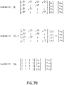
- At least one processor may be configured to: receive a first set of measurements of the antenna radiating elements 402 as a first measurement coding matrix (e.g., M 1 as shown in Equation 6 of FIG. 7B ).
- a first measurement coding matrix e.g., M 1 as shown in Equation 6 of FIG. 7B .
- the antenna array 106 comprises x antenna radiating elements 402, wherein x is an integer greater than or equal to 2, wherein the first measurement coding matrix is equal to a first matrix multiplied by the complex calibration coefficients, wherein the first matrix includes elements of ae jn ⁇ /4 , wherein for elements in the first matrix corresponding to a position of an x-th order Hadamard matrix having a value of 1: a equals 1 and n equals 3, wherein for elements in the first matrix corresponding to a position of the x-th order Hadamard matrix having a value of -1: a equals 1 and n equals 0.
- At least one processor may be configured to: receive a second set of measurements of the antenna radiating elements 402 as a second measurement coding matrix (e.g., M 2 as shown in Equation 7 of FIG. 7B ).
- a second measurement coding matrix e.g., M 2 as shown in Equation 7 of FIG. 7B .
- the antenna array 106 comprises x antenna radiating elements 402, wherein x is an integer greater than or equal to 2, wherein the second measurement coding matrix is equal to a second matrix multiplied by the complex calibration coefficients, wherein the second matrix includes elements of ae jn ⁇ /4 wherein for elements in the second matrix corresponding to a position of an x-th order Hadamard matrix having a value of 1: a equals 1 and n equals 7, wherein for elements in the second matrix corresponding to a position of the x-th order Hadamard matrix having a value of -1: a equals 1 and n equals 0.
- At least some of the antenna radiating elements 402 are coded with a first phase for the first set of measurements of the antenna radiating elements 402, and the at least some of the antenna radiating elements 402 are coded with a second phase for the second set of measurements of the antenna radiating elements 402, wherein the first phase and the second phase are in different quadrants of a phase circle (e.g., as shown in FIGS. 5 and 6 ).
- At least one processor may be configured to: receive a third set of measurements of the antenna radiating elements 402 as a third measurement coding matrix (e.g., M 3 as shown in Equation 8 of FIG. 7B ), wherein the third measurement coding matrix corresponds to all of the antenna radiating elements 402 being in a powered on state.
- a third measurement coding matrix e.g., M 3 as shown in Equation 8 of FIG. 7B
- the antenna array 106 comprises x antenna radiating elements 402, wherein x is an integer greater than or equal to 2, wherein the third measurement coding matrix is equal to a third matrix multiplied by the complex calibration coefficients, wherein the third matrix includes elements of ae jn ⁇ /4 , wherein for elements in the third matrix corresponding to a position of an x-th order Hadamard matrix having a value of 1: a equals 1 and n equals 0, wherein for elements in the third matrix corresponding to a position of the x-th order Hadamard matrix having a value of -1: a equals 1 and n equals 0.
- At least one processor may be configured to: receive a fourth set of measurements of the antenna radiating elements 402 as a fourth measurement coding matrix (e.g., M 4 as shown in Equation 9 of FIG. 7C ), wherein the fourth measurement coding matrix corresponds to all of the antenna radiating elements being in a powered down state.
- a fourth measurement coding matrix e.g., M 4 as shown in Equation 9 of FIG. 7C
- the antenna array 106 comprises x antenna radiating elements 402, wherein x is an integer greater than or equal to 2, wherein the fourth measurement coding matrix is equal to a fourth matrix multiplied by the complex calibration coefficients, wherein the fourth matrix includes elements of ae jn ⁇ /4 , wherein for elements in the fourth matrix corresponding to a position of an x-th order Hadamard matrix having a value of 1: a equals 0 and n equals 0, wherein for elements in the fourth matrix corresponding to a position of the x-th order Hadamard matrix having a value of -1: a equals 0 and n equals 0.
- At least one processor may be configured to: calculate a reference encoding matrix (e.g., E as shown in Equation 10 of FIG. 7C ) with coherent signal leakage de-embedded by subtracting the fourth measurement coding matrix from the third measurement coding matrix.
- a reference encoding matrix e.g., E as shown in Equation 10 of FIG. 7C
- At least one processor may be configured to: calculate a differential encoding matrix (e.g., F as shown in Equation 11 of FIG. 7C ) providing twice a signal-to-noise ratio by adding the first measurement coding matrix and the second measurement coding matrix.
- a differential encoding matrix e.g., F as shown in Equation 11 of FIG. 7C
- At least one processor may be configured to: calculate a differential matrix (e.g., G as shown in Equation 12 of FIG. 7C ) decoded back to conventional Hadamard matrix by subtracting the differential encoding matrix providing twice a signal-to-noise ratio from the reference encoding matrix with coherent signal leakage de-embedded.
- a differential matrix e.g., G as shown in Equation 12 of FIG. 7C
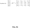
- At least one processor may be configured to: calculate complex calibration coefficients (e.g., ⁇ y i ⁇ as shown in Equation 13 of FIG. 7D ) for the antenna radiating elements 402 by multiplying an inverse Hadamard matrix by the differential matrix decoded back to conventional Hadamard matrix.
- the complex calibration coefficients include gain offset values and phase offset values.
- At least one processor may be configured to: program the antenna array 106 (e.g., program the gain and phase registers 404 (see FIGS. 4A-4B ) of the antenna array 106) with amplitude and phase offsets computed from the complex calibration coefficients.
- program the antenna array 106 e.g., program the gain and phase registers 404 (see FIGS. 4A-4B ) of the antenna array 106) with amplitude and phase offsets computed from the complex calibration coefficients.
- the antenna array 106 is configured to form an antenna beam more accurately (e.g., with improved definition between lobes for an antenna beam cross-section) than prior to the antenna array 106 being programmed with the amplitude and phase offsets computed from the complex calibration coefficients.
- equations which may be used in an exemplary embodiment of testing and/or calibrating an exemplary antenna array 106 having four antenna radiating elements 402, are shown according to the inventive concepts disclosed herein.
- the exemplary matrices, shown in FIGS. 7A , 7B , 7C , and 7D are for an antenna array 106 with four antenna radiating elements 402 in an array of 2-elements by 2-elements and are used as an example to illustrate the concept; some embodiments, may include using adapted versions of such equations (as would be apparent to one of ordinary skill in the art) to calibrate an antenna array 106 having any number of antenna radiating elements 402.
- Antenna radiating elements 402 are represented as columns, the coding states are represented as rows, and the operating state for any given element is the value in the particular row/column position (e.g. the operational state for element #1, coding state #1 is denoted by the value in row #1/column#1).
- At least one processor e.g., the at least one processor 202 and/or the at least one processor 302 may be configured to apply the equations of FIGS. 7A , 7B , 7C , and 7D and perform calculations described in and/or related to the equations of FIGS. 7A , 7B , 7C , and 7D .
- Equation 1 of FIG. 7A for an exemplary antenna array 106 (e.g., an ESA) having four antenna radiating elements 402, the Hadamard matrix may be used as a basis for calibrating the antenna array 106.
- a Hadamard matrix can be generated by using Equation 1.
- H 2 k equals the generalized form of Hadamard matrix.
- H 2 k-1 equals the matrix of reference and encoding states.
- H 2 may equal orthogonally arranged reference and encoding states.
- Equation 3 of FIG. 7A one of the important properties of the Hadamard matrix is that, for H being a Hadamard matrix of order n, the transpose of H is closely related to its inverse, as shown in Equation 3.
- n equals the order of the Hadamard matrix.
- H equals the Hadamard matrix of the n th order.
- H T equals the transpose of the Hadamard matrix of the n th order.
- I n equals the identity matrix of size n by n.
- the target may be to calibrate the antenna array 106 with this orthogonal set of code.
- H 4 equals conventional Hadamard Codes for four orthogonal state arrangements.
- 1 refers to an element reference state.
- -1 refers to an element encoded state.
- H 4 of Equation 5 may be used to calibrate the antenna array 106 with phase variation.
- H 4 may be the generalized form of Hadamard Codes of amplitude and phase arrangements for a 2-element by 2-element antenna array (4 elements total).
- a an amplitude coefficient for each antenna radiating element 402 at each coding state.
- e Euler's number.
- j an imaginary operator (V-1).
- V an imaginary operator
- ⁇ equals the number pi.
- n equals a value (e.g., a real valued number between zero (0) and eight (8)) of coding state determining reference angle and encoded angle.
- M 1 is a first measurement coding matrix corresponding to a first set of measurements with all amplitude coefficients ('a') equal to 1, representing an absolute power level at an optimum gain setting (typically in the linear gain region before compression).
- a amplitude coefficients
- n n
- e j ⁇ (3/4) equals an encoded state with value 'n' of three for a phase angle of 135 degrees. That is, 1 equals a reference state with value 'n' of zero for a phase angle of zero degrees.
- y 1 equals an unknown complex calibration coefficient for antenna radiating element #1 (to be solved for).
- y 2 equals an unknown complex calibration coefficient for antenna radiating element #2 (to be solved for).
- y 3 equals an unknown complex calibration coefficient for antenna radiating element #3 (to be solved for).
- y 4 equals an unknown complex calibration coefficient for element #4 (to be solved for).
- m 1 equals a measured value obtained when antenna radiating elements are in "M 1 " coding state #1 (row#1).
- m 2 equals a measured value obtained when antenna radiating elements are in "M 1 " coding state #2 (row#2).
- m 3 equals a measured value obtained when antenna radiating elements are in "M 1 " coding state #3 (row#3).
- m 4 equals a measured value obtained when antenna radiating elements are in "M 1 " coding state #4 (row#4).
- ⁇ y i ⁇ are the complex gain and phase offsets for each individual antenna radiating element 402
- ⁇ m j ⁇ are each measurement taken from a vector network analyzer.
- M 2 is a second measurement coding matrix corresponding to a second set of measurements with all amplitude coefficients ('a') equal to 1.
- a For elements in the second measurement coding matrix corresponding to a position of an x-th (where x is greater than or equal to 2) order Hadamard matrix having a value of 1: a equals 1 and n equals 7.
- a For elements in the second measurement coding matrix corresponding to a position of the x-th order Hadamard matrix having a value of -1: a equals 1 and n equals 0. That is, e j ⁇ (7/4) equals an encoded state with value 'n' of seven for a phase angle of 315 degrees.
- 1 a reference state with value 'n' of zero for a phase angle of zero degrees.
- m 5 a measured value obtained when antenna radiating elements are in "M 2 " coding state #1 (row#1).
- m 6 equals a measured value obtained when antenna radiating elements are in "M 2 " coding state #2 (row#2).
- m 7 equals a measured value obtained when antenna radiating elements are in "M 2 " coding state #3 (row#3).
- m 8 equals a measured value obtained when antenna radiating elements are in "M 2 " coding state #4 (row#4).
- M 3 is a third measurement coding matrix corresponding to a third set of measurements with all amplitude coefficients ('a') equal to 1.
- a For elements in the third measurement coding matrix corresponding to a position of an x-th (where x is greater than or equal to 2) order Hadamard matrix having a value of 1: a equals 1 and n equals 0.
- a For elements in the third measurement coding matrix corresponding to a position of the x-th order Hadamard matrix having a value of -1: a equals 1 and n equals 0. That is, 1 equals a reference state with value 'n' of zero for a phase angle of zero degrees.
- mg equals a measured value obtained when antenna radiating elements are in "M 3 " coding state #1 (row#1).
- m 10 equals mg.
- m 11 equals mg.
- m 12 equals mg.
- M 4 is a fourth measurement coding matrix corresponding to a fourth set of measurements with all amplitude coefficients ('a') equal to 0 (i.e., in a powered down state).
- a a position of an x-th
- n a value of a position of the x-th order Hadamard matrix having a value of -1.
- a a reference state with an antenna radiating element in a powered down state.
- m 13 equals a measured value obtained when antenna radiating elements are in "M 4 " coding state #1 (row#1).
- m 14 equals m 13 .
- m 15 equals m 13 .
- m 16 equals m 13 .
- Each row of M 3 is a single measurement with one reference encoding
- each row of M 4 is a single measurement with one reference encoding. These two reference measurements may only need to be taken once during the start of the calibration process. The rows are fully populated in these matrices with the same values as mathematical placeholders.
- Equation 10 of FIG. 7C E equals a reference encoding matrix with coherent signal leakage de-embedded (M 3 - M 4 ). Performing the operation of M 3 - M 4 cancels out coherent signal leakage from antenna array 106 to the antenna probe 102 through all antenna radiating elements 402. Some embodiments may omit this operation where phase coherent signal leakage is negligible.
- F a differential encoding matrix providing twice a signal-to-noise ratio. Adding the first measurement coding matrix and the second measurement coding matrix yields twice the signal amplitude to noise ratio, improving accuracy of results.
- G equals a differential matrix decoded back to conventional Hadamard matrix by subtracting the differential encoding matrix providing twice a signal-to-noise ratio from the reference encoding matrix, or from the reference encoding matrix with coherent signal leakage de-embedded.
- the orthogonal properties of a Hadamard matrix allow us to decode Hadamard matrix's operation on the unknown coefficients with the inverse Hadamard matrix and calculate the calibration coefficients ⁇ y i ⁇ for each of the antenna radiating elements 402.
- Calculating the complex calibration coefficients for the antenna radiating elements 402 may include multiplying an inverse Hadamard matrix by the differential matrix decoded back to conventional Hadamard matrix.
- an exemplary embodiment of a method 800 may include one or more of the following steps. Additionally, for example, some embodiments may include performing one more instances of the method 800 iteratively, concurrently, and/or sequentially. Additionally, for example, at least some of the steps of the method 800 may be performed in parallel and/or concurrently. Additionally, in some embodiments, at least some of the steps of the method 800 may be performed non-sequentially.
- a step 802 may include using, by at least one processor communicatively coupled to an antenna array comprising antenna radiating elements, a generalized form of Hadamard Codes to perform measurements of the antenna radiating elements, the generalized form of Hadamard Codes including amplitude coefficients and phase coefficients for the antenna radiating elements.
- a step 804 may include receiving, by the at least one processor, a first set of measurements of the antenna radiating elements as a first measurement coding matrix.
- a step 806 may include receiving, by the at least one processor, a second set of measurements of the antenna radiating elements as a second measurement coding matrix.
- a step 808 may include receiving, by the at least one processor, a third set of measurements of the antenna radiating elements as a third measurement coding matrix, wherein the third measurement coding matrix corresponds to all of the antenna radiating elements being in a powered on state.
- a step 810 may include receiving, by the at least one processor, a fourth set of measurements of the antenna radiating elements as a fourth measurement coding matrix, wherein the fourth measurement coding matrix corresponds to all of the antenna radiating elements being in a powered down state.
- a step 812 may include calculating, by the at least one processor, a reference encoding matrix with coherent signal leakage de-embedded by subtracting the fourth measurement coding matrix from the third measurement coding matrix.
- a step 814 may include calculating, by the at least one processor, a differential encoding matrix providing twice a signal-to-noise ratio by adding the first measurement coding matrix and the second measurement coding matrix.
- a step 816 may include calculating, by the at least one processor, a differential matrix decoded back to conventional Hadamard matrix by subtracting the differential encoding matrix providing twice a signal-to-noise ratio from the reference encoding matrix with coherent signal leakage de-embedded.
- a step 818 may include calculating, by the at least one processor, complex calibration coefficients for the antenna radiating elements by multiplying an inverse Hadamard matrix by the differential matrix decoded back to conventional Hadamard matrix.
- a step 820 may include programming, by the at least one processor, the antenna array with amplitude and phase offsets computed from the complex calibration coefficients.
- method 800 may include any of the operations disclosed throughout.
- embodiments of the inventive concepts disclosed herein may be directed to a method and a system configured to test and/or calibrate an antenna array.
- At least one non-transitory computer-readable medium may refer to as at least one non-transitory computer-readable medium (e.g., at least one computer-readable medium implemented as hardware; e.g., at least one non-transitory processor-readable medium, at least one memory (e.g., at least one nonvolatile memory, at least one volatile memory, or a combination thereof; e.g., at least one random-access memory, at least one flash memory, at least one read-only memory (ROM) (e.g., at least one electrically erasable programmable read-only memory (EEPROM)), at least one on-processor memory (e.g., at least one on-processor cache, at least one on-processor buffer, at least one on-processor flash memory, at least one on-processor EEPROM, or a combination thereof), at least one storage device (e.g., at least one hard-disk drive, at least one tape drive, at
- At least one means one or a plurality of; for example, “at least one” may comprise one, two, three, ..., one hundred, or more.
- one or more means one or a plurality of; for example, “one or more” may comprise one, two, three, ..., one hundred, or more.
- zero or more means zero, one, or a plurality of; for example, “zero or more” may comprise zero, one, two, three, ..., one hundred, or more.
- the methods, operations, and/or functionality disclosed may be implemented as sets of instructions or software readable by a device. Further, it is understood that the specific order or hierarchy of steps in the methods, operations, and/or functionality disclosed are examples of exemplary approaches. Based upon design preferences, it is understood that the specific order or hierarchy of steps in the methods, operations, and/or functionality can be rearranged while remaining within the scope of the inventive concepts disclosed herein and as defined by the claims. The accompanying claims may present elements of the various steps in a sample order, and are not necessarily meant to be limited to the specific order or hierarchy presented.
- embodiments of the methods according to the inventive concepts disclosed herein may include one or more of the steps described herein. Further, such steps may be carried out in any desired order and two or more of the steps may be carried out simultaneously with one another. Two or more of the steps disclosed herein may be combined in a single step, and in some embodiments, one or more of the steps may be carried out as two or more sub-steps. Further, other steps or sub-steps may be carried in addition to, or as substitutes to one or more of the steps disclosed herein.
- inventive concepts disclosed herein are well adapted to carry out the objects and to attain the advantages mentioned herein as well as those inherent in the inventive concepts disclosed herein. While presently preferred embodiments of the inventive concepts disclosed herein have been described for purposes of this disclosure, it will be understood that numerous changes may be made which will readily suggest themselves to those skilled in the art and which are accomplished within the broad scope and coverage of the inventive concepts disclosed and claimed herein, as defined by the claims.
Landscapes
- Physics & Mathematics (AREA)
- Electromagnetism (AREA)
- Engineering & Computer Science (AREA)
- Computer Networks & Wireless Communication (AREA)
- Signal Processing (AREA)
- Variable-Direction Aerials And Aerial Arrays (AREA)
Abstract
Description
- The present application is related to
U.S. Patent Application No. 16/147,457, filed September 8, 2018 U.S. Patent Application No. 62/725,857, filed August 31, 2018 - Antenna technology is rapidly progressing in the area of antenna arrays (e.g., active phased array antennas, commonly referred to as electronically steered antennas (ESAs)), that employ either digital or analog beamforming technologies to control the gain and phase settings of individual antenna elements (e.g., radiating elements) in order to electronically steer the resulting beam.
- This physical arrangement of many small beam forming devices in a single system allows for functionality that previously required larger passive (e.g., slotted waveguide) antennas, accompanied by mechanical hardware, to physically point the antenna at a target location. Among other advantages in signal processing (such as dual polarization and utilizing multiple beams) this technology also improves control over directionality, which leads to improvement in Low Probability of Intercept (LPI) and Low Probability of Detection (LPD).
- Along with this new technology comes new challenges for system calibration of ESAs. Calibration is a necessary process for accurate performance and compensation of manufacturing variations.
- Existing methods to calibrate ESAs use Near Field (NF) and Far Field (FF) approaches. Both of these require anechoic chambers of significant facility size with accurate positioning systems to translate receiver and emitter sources (e.g., an electromagnetic field probe) across known coordinate space relative to the ESA. Both are time consuming processes to complete.
- In one aspect, embodiments of the inventive concepts disclosed herein are directed to a system. The system may include an antenna array including antenna radiating elements. The system may further include a processor communicatively coupled to the antenna array. The processor may be configured to: use a generalized form of Hadamard Codes to perform measurements of the antenna radiating elements, the generalized form of Hadamard Codes including amplitude coefficients and phase coefficients for the antenna radiating elements; receive a first set of measurements of the antenna radiating elements as a first measurement coding matrix; receive a second set of measurements of the antenna radiating elements as a second measurement coding matrix; receive a third set of measurements of the antenna radiating elements as a third measurement coding matrix, wherein the third measurement coding matrix corresponds to all of the antenna radiating elements being in a powered on state; receive a fourth set of measurements of the antenna radiating elements as a fourth measurement coding matrix, wherein the fourth measurement coding matrix corresponds to all of the antenna radiating elements being in a powered down state; calculate a reference encoding matrix with coherent signal leakage de-embedded by subtracting the fourth measurement coding matrix from the third measurement coding matrix; calculate a differential encoding matrix providing twice a signal-to-noise ratio by adding the first measurement coding matrix and the second measurement coding matrix; calculate a differential matrix decoded back to conventional Hadamard matrix by subtracting the differential encoding matrix providing twice a signal-to-noise ratio from the reference encoding matrix with coherent signal leakage de-embedded; calculate complex calibration coefficients for the antenna radiating elements by multiplying an inverse Hadamard matrix by the differential matrix decoded back to conventional Hadamard matrix; and program the antenna array with amplitude and phase offsets computed from the complex calibration coefficients.
- In a further aspect, embodiments of the inventive concepts disclosed herein are directed to a method. The method may include: using, by at least one processor communicatively coupled to an antenna array comprising antenna radiating elements, a generalized form of Hadamard Codes to perform measurements of the antenna radiating elements, the generalized form of Hadamard Codes including amplitude coefficients and phase coefficients for the antenna radiating elements; receiving, by the at least one processor, a first set of measurements of the antenna radiating elements as a first measurement coding matrix; receiving, by the at least one processor, a second set of measurements of the antenna radiating elements as a second measurement coding matrix; receiving, by the at least one processor, a third set of measurements of the antenna radiating elements as a third measurement coding matrix, wherein the third measurement coding matrix corresponds to all of the antenna radiating elements being in a powered on state; receiving, by the at least one processor, a fourth set of measurements of the antenna radiating elements as a fourth measurement coding matrix, wherein the fourth measurement coding matrix corresponds to all of the antenna radiating elements being in a powered down state; calculating, by the at least one processor, a reference encoding matrix with coherent signal leakage de-embedded by subtracting the fourth measurement coding matrix from the third measurement coding matrix; calculating, by the at least one processor, a differential encoding matrix providing twice a signal-to-noise ratio by adding the first measurement coding matrix and the second measurement coding matrix; calculating, by the at least one processor, a differential matrix decoded back to conventional Hadamard matrix by subtracting the differential encoding matrix providing twice a signal-to-noise ratio from the reference encoding matrix with coherent signal leakage de-embedded; calculating, by the at least one processor, complex calibration coefficients for the antenna radiating elements by multiplying an inverse Hadamard matrix by the differential matrix decoded back to conventional Hadamard matrix; and programming, by the at least one processor, the antenna array with amplitude and phase offsets computed from the complex calibration coefficients.
- Implementations of the inventive concepts disclosed herein may be better understood when consideration is given to the following detailed description thereof. Such description makes reference to the included drawings, which are not necessarily to scale, and in which some features may be exaggerated and some features may be omitted or may be represented schematically in the interest of clarity. Like reference numerals in the drawings may represent and refer to the same or similar element, feature, or function. In the drawings:
-
FIG. 1 is a view of an exemplary embodiment of a system according to the inventive concepts disclosed herein. -
FIG. 2 is an exemplary test equipment of the system ofFIG. 1 according to the inventive concepts disclosed herein. -
FIG. 3 is an exemplary computing device of the system ofFIG. 1 according to the inventive concepts disclosed herein. -
FIGS. 4A and 4B show an exemplary antenna array of the system ofFIG. 1 according to the inventive concepts disclosed herein. -
FIGS. 5 and6 illustrate writing phase offset values into two quadrants of a phase circle so as to provide both positive and negative vector components according to the inventive concepts disclosed herein. -
FIGS. 7A ,7B ,7C ,7D show equations, which may be used in an exemplary embodiment of testing and/or calibrating an exemplary antenna array, according to the inventive concepts disclosed herein. -
FIG. 8 is a diagram of an exemplary embodiment of a method according to the inventive concepts disclosed herein. - Before explaining at least one embodiment of the inventive concepts disclosed herein in detail, it is to be understood that the inventive concepts are not limited in their application to the details of construction and the arrangement of the components or steps or methodologies set forth in the following description or illustrated in the drawings. In the following detailed description of embodiments of the instant inventive concepts, numerous specific details are set forth in order to provide a more thorough understanding of the inventive concepts. However, it will be apparent to one of ordinary skill in the art having the benefit of the instant disclosure that the inventive concepts disclosed herein may be practiced without these specific details. In other instances, well-known features may not be described in detail to avoid unnecessarily complicating the instant disclosure. The inventive concepts disclosed herein are capable of other embodiments or of being practiced or carried out in various ways. Also, it is to be understood that the phraseology and terminology employed herein is for the purpose of description and should not be regarded as limiting.
- As used herein a letter following a reference numeral is intended to reference an embodiment of the feature or element that may be similar, but not necessarily identical, to a previously described element or feature bearing the same reference numeral (e.g., 1, 1a, 1b). Such shorthand notations are used for purposes of convenience only, and should not be construed to limit the inventive concepts disclosed herein in any way unless expressly stated to the contrary.
- Further, unless expressly stated to the contrary, "or" refers to an inclusive or and not to an exclusive or. For example, a condition A or B is satisfied by anyone of the following: A is true (or present) and B is false (or not present), A is false (or not present) and B is true (or present), and both A and B are true (or present).
- In addition, use of the "a" or "an" are employed to describe elements and components of embodiments of the instant inventive concepts. This is done merely for convenience and to give a general sense of the inventive concepts, and "a" and "an" are intended to include one or at least one and the singular also includes the plural unless it is obvious that it is meant otherwise.
- Finally, as used herein any reference to "one embodiment," or "some embodiments" means that a particular element, feature, structure, or characteristic described in connection with the embodiment is included in at least one embodiment of the inventive concepts disclosed herein. The appearances of the phrase "in some embodiments" in various places in the specification are not necessarily all referring to the same embodiment, and embodiments of the inventive concepts disclosed may include one or more of the features expressly described or inherently present herein, or any combination or sub-combination of two or more such features, along with any other features which may not necessarily be expressly described or inherently present in the instant disclosure.
- Broadly, embodiments of the inventive concepts disclosed herein are directed to a method and a system configured to test and/or calibrate an antenna array (e.g., an active phased array antenna, commonly referred to as an ESA). Some embodiments may include an automated calibration solution for calibrating and/or recalibrating ESA antennas. Some embodiments may use the techniques described herein in a manual fashion. Various environmental conditions, operating location, and desired changes to operating frequencies may drive a customer need for a convenient solution to quickly calibrate an ESA antenna. Some embodiments disclosed herein may be implemented as a software package executed by a processor causing the calibration solution to be performed.
- Referring now to
FIGS. 1 ,2 ,3 ,4A, and 4B , exemplary embodiments of asystem 100 according to the inventive concepts disclosed herein are depicted. Thesystem 100 may be implemented as any suitable system. For example, as shown inFIG. 1 , thesystem 100 may include at least oneantenna probe 102, at least oneenclosure 104, at least oneantenna array 106, at least oneantenna mount 108, at least onecomputing device 110, and/or at least onetest equipment 112, some or all of which may be communicatively coupled at any given time. - Some embodiments may include at least one processor (e.g., at least one
processor 202 and/or at least one processor 302) computing gain and phase offset values for each individualantenna radiating element 402 of an antenna array 106 (e.g., a phased array antenna). These gain and phase offset values may be used as a calibration factors (e.g., calibration coefficients) by system firmware (e.g., maintained in a non-transitory computer-readable medium, such asmemory 204 and/or 304) to account for manufacturing tolerances and behavioral changes across frequency and temperature, enabling the system and/orantenna array 106 to achieve optimum performance. For example, anuncalibrated antenna array 106 may be placed in an enclosure 104 (e.g., an exceptionally small anechoic chamber enclosure) fixture on astationary antenna mount 108. Theantenna array 106 may be orthogonally aligned to astationary antenna probe 102.Test equipment 112 may provide power to theantenna array 106, source vector measurement stimulus signals, and capture composite vector measurement responses. Thecomputing device 110 may communicate with theantenna array 106 to set the individualradiating elements 402 to coding patterns (e.g., various sets of reference and encoding states) as defined in the equations herein (e.g., as shown inFIGS. 7A ,7B ,7C , and7D ). Thecomputing device 110 executing software may capture measured results from thetest equipment 112 and may synchronize the measured results with each known coding state. Thecomputing device 110 executing software may perform a calculation to compensate for the physics of theantenna probe 102 using a ray tracing algorithm to locate the phase center of theprobe 102 at the specific frequency of calibration, then may process the results according to the defined equations (e.g., as shown inFIGS. 7A ,7B ,7C , and7D ) to yield a complex calibration coefficient for each individual antenna radiating element. This list of results may be used by at least one processor (e.g., 202 and/or 302) executing firmware to compute relative gain and/or phase offsets to be applied to control registers for each individual antenna radiating element 402 (typically in the form of a calibration file or memory table). - For example, the
antenna array 106 may be a phased array antenna (e.g., an active phased array antenna, commonly referred to as an ESA). Theantenna array 106 may includeantenna radiating elements 402 and gain and phase registers 404, as shown inFIGS. 4A and 4B . Each of theantenna radiating elements 402 may be in a powered on state or a powered down state. For example, some or all of theantenna radiating elements 402 may be in a powered on state at a given time. For example, some or all of theantenna radiating elements 402 may be in a powered down state at a given time. While theantenna array 106 exemplarily is depicted with fourantenna radiating elements 402 for illustrative purposes, theantenna array 106 may include any suitable number ofantenna radiating elements 402, such as hundreds, thousands, or more. Theantenna array 106 may be programmed (e.g., by the at least oneprocessor 202 and/or the at least one processor 302) with the complex calibration coefficients, such as by programming control registers on theantenna array 106 and each control register associated with at least one givenantenna radiating element 402. - Referring to
FIGS. 4A and 4B , the issue with existing calibration techniques using ON/OFF element coding is that the existing calibration techniques rely on the assumption that mutual coupling between a single activeantenna radiating element 402 and another individual coupledelement 402 on theantenna array 106 is the same, whether or not the coupledelement 402 is active (ON) as shown inFIG. 4A , or in a power down (OFF) state as shown inFIG. 4B . In reality the physical coupling may not be the same between these two states, which can lead to errors in the calibration results and diminish the benefit of existing approaches. The principle behind the existing approach using ON/OFF element coding is the assumption that there is a linear relationship between the coupling of eachelement 402 to the stationarycalibration antenna probe 102 under encoding conditions. More importantly, the encoding of a single element 402 (e.g. switching an element from ON to OFF) may have a negligible effect on the coupling ofneighboring elements 402. Again, for the existing calibration approaches, the assumption throughout the ON/OFF encoding process is that anelement 402 in the OFF state is ideally terminated and, therefore, not causing changes in the mutual coupling to itsneighboring elements 402. For certain planar aperture design configurations, with symmetrical element placement, and good isolation between elements (i.e. low mutual coupling) this ON/OFF encoding process can yield usable results that can still meet the target specifications, but may not hold in the general case for any active phased array antenna. In reality anelement 402 in the OFF state may not be ideally terminated and may re-radiate energy from the element'sneighboring elements 402. The neighboring elements 402 (which would normally re-radiate some energy from theelement 402 that is OFF) may not do so. From the perspective of thetest antenna probe 102, turning anantenna radiating element 402 from ON to OFF may result in a larger difference in signal than would be seen from anisolated element 402 changing from ON to OFF because the overall power level of test signal compared to the noise floor noise may be much greater. Some embodiments expand on the fundamental idea behind the differential ON/OFF element coding approach by using differential measurements with alternating phase coding to improve calibration results. Some embodiments use multiple sets of differential measurements with multiple phase code settings. - As illustrated in
FIGS. 5 and6 , some embodiments may include writing (e.g., alternately writing) phase offset values into two quadrants of a phase circle so as to provide both positive and negative vector components (e.g., within the possible degrees of freedom) as illustrated inFIGS. 5 and6 . This approach can be expanded to include any or all potential angles that embedded phase shifters of theantenna array 106 can be set to. With the reference phase angle of 0 degrees oriented on the right-hand side, the exemplary phase angles that provide these exemplary components are 135 degrees and 315 degrees as shown inFIG. 5 , though in some embodiments, any suitable phase angles may be used. The measurements at these angles may be compared to a reference measurement with allantenna radiating elements 402 coded at 0 degrees. This approach may also include another reference measurement with allantenna radiating elements 402 in the power down state (i.e. OFF) to subtract out coherent signal leakage (not ambient noise or additive white Gaussian noise) at the calibration frequency from thetest equipment 112 source to the probe 102 (in transmit) and from thetest equipment 112 source to the antenna array 106 (e.g., an ESA) (in receive). This coherent signal leakage may be obtained through the operation of a network analyzer that has a receiver synchronized in lock-step with a signal source. Some embodiments may include the use of multiple phase code settings versus only two settings of existing approaches. The multiple phase code settings may include one measurement for each code, along with two global reference measurements (e.g., allelements 402 OFF for quantifying coherent signal leakage at the calibrated frequency, and allelements 402 ON for a reference field measurement). In some embodiments, using such multiple phase settings may maximize the benefit of greater signal to noise ratio while also eliminating the assumption regarding mutual coupling because allantenna radiating elements 402 may be active for all measurements (except the leakage measurement where allantenna radiating elements 402 are in the OFF power down state). In some embodiments, with this approach, there may never be a situation where there is some mix ofantenna radiating elements 402 that are ON andantenna radiating elements 402 that are OFF, meaning that mutual coupling is truly the same for all phase coding that is applied. - Referring again to
FIGS. 1-3 , thecomputing device 110 may include at least oneprocessor 302 and at least onememory 304, which may be communicatively coupled. The at least oneprocessor 302 may be implemented as any suitable type and number of processors. For example, the at least oneprocessor 302 may include at least one general purpose processor (e.g., at least one central processing unit (CPU)), at least one digital signal processor (DSP), at least one application specific integrated circuit (ASIC), and/or at least one field-programmable gate array (FPGA). The at least oneprocessor 302 may be configured to perform (e.g., collectively perform if more than one processor) any or all of the operations disclosed throughout. Theprocessor 104 may be configured to run various software and/or firmware applications and/or computer code stored (e.g., maintained) in a non-transitory computer-readable medium (e.g., memory 304) and configured to execute various instructions or operations. - The
test equipment 112 may include at least oneprocessor 202, at least onememory 204, and/or at least onevector network analyzer 206, some or all of which may be communicatively coupled. The at least oneprocessor 202 may be implemented as any suitable type and number of processors. For example, the at least oneprocessor 202 may include at least one general purpose processor (e.g., at least one central processing unit (CPU)), at least one digital signal processor (DSP), at least one application specific integrated circuit (ASIC), and/or at least one field-programmable gate array (FPGA). The at least oneprocessor 202 may be configured to perform (e.g., collectively perform if more than one processor) any or all of the operations disclosed throughout. Theprocessor 202 may be configured to run various software and/or firmware applications and/or computer code stored (e.g., maintained) in a non-transitory computer-readable medium (e.g., memory 204) and configured to execute various instructions or operations. Thevector network analyzer 206 may be an industry standard instrument. By using an internal reference signal compared to a sourced signal in synch with the vector network analyzer's 206 receiver, thevector network analyzer 206 may be used to capture composite radiofrequency (RF) signal's complex amplitude and phase as processed by anantenna array 106 and probe 102 in each of the Hadamard encoded states (e.g., thevector network analyzer 206 may directly measure "m1" through "m16" in the four-element array example (e.g., illustrated in the equations ofFIGS 7B-7D ) used to describe various concepts of this disclosure). - In some embodiments, at least one processor (e.g., the at least one
processor 202 and/or the at least one processor 302) may be configured to perform (e.g., collectively perform if more than one processor) any or all of the operations disclosed throughout. - For example, at least one processor (e.g., the at least one
processor 202 and/or the at least one processor 302) may be configured to: use a generalized form of Hadamard Codes (e.g., as shown inEquation 5 ofFIG. 7A ) to perform measurements of theantenna radiating elements 402, the generalized form of Hadamard Codes including amplitude coefficients and phase coefficients written to gain and phase registers 404 (seeFIGS. 4A-B ) for theantenna radiating elements 402. In some embodiments, the generalized form of Hadamard Codes has elements equal to aejnπ/4, wherein a is an amplitude coefficient for eachantenna radiating element 402 at each coding state, wherein e is Euler's number, wherein j (i.e. (-1)1/2) is an imaginary operator, wherein n is a real number value of coding state between zero (0) and eight (8) determining reference angle and encoded angle. - For example, at least one processor (e.g., the at least one
processor 202 and/or the at least one processor 302) may be configured to: receive a first set of measurements of theantenna radiating elements 402 as a first measurement coding matrix (e.g., M1 as shown in Equation 6 ofFIG. 7B ). In some embodiments, theantenna array 106 comprises xantenna radiating elements 402, wherein x is an integer greater than or equal to 2, wherein the first measurement coding matrix is equal to a first matrix multiplied by the complex calibration coefficients, wherein the first matrix includes elements of aejnπ/4, wherein for elements in the first matrix corresponding to a position of an x-th order Hadamard matrix having a value of 1: aequals 1 and n equals 3, wherein for elements in the first matrix corresponding to a position of the x-th order Hadamard matrix having a value of -1: aequals 1 and n equals 0. - For example, at least one processor (e.g., the at least one
processor 202 and/or the at least one processor 302) may be configured to: receive a second set of measurements of theantenna radiating elements 402 as a second measurement coding matrix (e.g., M2 as shown in Equation 7 ofFIG. 7B ). In some embodiments, theantenna array 106 comprises xantenna radiating elements 402, wherein x is an integer greater than or equal to 2, wherein the second measurement coding matrix is equal to a second matrix multiplied by the complex calibration coefficients, wherein the second matrix includes elements of aejnπ/4 wherein for elements in the second matrix corresponding to a position of an x-th order Hadamard matrix having a value of 1: aequals 1 and n equals 7, wherein for elements in the second matrix corresponding to a position of the x-th order Hadamard matrix having a value of -1: aequals 1 and n equals 0. In some embodiments, at least some of theantenna radiating elements 402 are coded with a first phase for the first set of measurements of theantenna radiating elements 402, and the at least some of theantenna radiating elements 402 are coded with a second phase for the second set of measurements of theantenna radiating elements 402, wherein the first phase and the second phase are in different quadrants of a phase circle (e.g., as shown inFIGS. 5 and6 ). - For example, at least one processor (e.g., the at least one
processor 202 and/or the at least one processor 302) may be configured to: receive a third set of measurements of theantenna radiating elements 402 as a third measurement coding matrix (e.g., M3 as shown inEquation 8 ofFIG. 7B ), wherein the third measurement coding matrix corresponds to all of theantenna radiating elements 402 being in a powered on state. In some embodiments, theantenna array 106 comprises xantenna radiating elements 402, wherein x is an integer greater than or equal to 2, wherein the third measurement coding matrix is equal to a third matrix multiplied by the complex calibration coefficients, wherein the third matrix includes elements of aejnπ/4, wherein for elements in the third matrix corresponding to a position of an x-th order Hadamard matrix having a value of 1: aequals 1 and n equals 0, wherein for elements in the third matrix corresponding to a position of the x-th order Hadamard matrix having a value of -1: aequals 1 and n equals 0. - For example, at least one processor (e.g., the at least one
processor 202 and/or the at least one processor 302) may be configured to: receive a fourth set of measurements of theantenna radiating elements 402 as a fourth measurement coding matrix (e.g., M4 as shown inEquation 9 ofFIG. 7C ), wherein the fourth measurement coding matrix corresponds to all of the antenna radiating elements being in a powered down state. In some embodiments, theantenna array 106 comprises xantenna radiating elements 402, wherein x is an integer greater than or equal to 2, wherein the fourth measurement coding matrix is equal to a fourth matrix multiplied by the complex calibration coefficients, wherein the fourth matrix includes elements of aejnπ/4, wherein for elements in the fourth matrix corresponding to a position of an x-th order Hadamard matrix having a value of 1: aequals 0 and n equals 0, wherein for elements in the fourth matrix corresponding to a position of the x-th order Hadamard matrix having a value of -1: aequals 0 and n equals 0. - For example, at least one processor (e.g., the at least one
processor 202 and/or the at least one processor 302) may be configured to: calculate a reference encoding matrix (e.g., E as shown inEquation 10 ofFIG. 7C ) with coherent signal leakage de-embedded by subtracting the fourth measurement coding matrix from the third measurement coding matrix. - For example, at least one processor (e.g., the at least one
processor 202 and/or the at least one processor 302) may be configured to: calculate a differential encoding matrix (e.g., F as shown inEquation 11 ofFIG. 7C ) providing twice a signal-to-noise ratio by adding the first measurement coding matrix and the second measurement coding matrix. - For example, at least one processor (e.g., the at least one
processor 202 and/or the at least one processor 302) may be configured to: calculate a differential matrix (e.g., G as shown inEquation 12 ofFIG. 7C ) decoded back to conventional Hadamard matrix by subtracting the differential encoding matrix providing twice a signal-to-noise ratio from the reference encoding matrix with coherent signal leakage de-embedded. - For example, at least one processor (e.g., the at least one
processor 202 and/or the at least one processor 302) may be configured to: calculate complex calibration coefficients (e.g., {yi} as shown inEquation 13 ofFIG. 7D ) for theantenna radiating elements 402 by multiplying an inverse Hadamard matrix by the differential matrix decoded back to conventional Hadamard matrix. In some embodiments, the complex calibration coefficients include gain offset values and phase offset values. - For example, at least one processor (e.g., the at least one
processor 202 and/or the at least one processor 302) may be configured to: program the antenna array 106 (e.g., program the gain and phase registers 404 (seeFIGS. 4A-4B ) of the antenna array 106) with amplitude and phase offsets computed from the complex calibration coefficients. In some embodiments, once theantenna array 106 is programmed with the amplitude and phase offsets computed from the complex calibration coefficients, theantenna array 106 is configured to form an antenna beam more accurately (e.g., with improved definition between lobes for an antenna beam cross-section) than prior to theantenna array 106 being programmed with the amplitude and phase offsets computed from the complex calibration coefficients. - Referring now to
FIGS. 7A ,7B ,7C , and7D , equations, which may be used in an exemplary embodiment of testing and/or calibrating anexemplary antenna array 106 having fourantenna radiating elements 402, are shown according to the inventive concepts disclosed herein. The exemplary matrices, shown inFIGS. 7A ,7B ,7C , and7D , are for anantenna array 106 with fourantenna radiating elements 402 in an array of 2-elements by 2-elements and are used as an example to illustrate the concept; some embodiments, may include using adapted versions of such equations (as would be apparent to one of ordinary skill in the art) to calibrate anantenna array 106 having any number ofantenna radiating elements 402.Antenna radiating elements 402 are represented as columns, the coding states are represented as rows, and the operating state for any given element is the value in the particular row/column position (e.g. the operational state forelement # 1,coding state # 1 is denoted by the value inrow # 1/column#1). At least one processor (e.g., the at least oneprocessor 202 and/or the at least one processor 302) may be configured to apply the equations ofFIGS. 7A ,7B ,7C , and7D and perform calculations described in and/or related to the equations ofFIGS. 7A ,7B ,7C , and7D . - Referring now to
Equation 1 ofFIG. 7A , for an exemplary antenna array 106 (e.g., an ESA) having fourantenna radiating elements 402, the Hadamard matrix may be used as a basis for calibrating theantenna array 106. In general, a Hadamard matrix can be generated by usingEquation 1. H2 k equals the generalized form of Hadamard matrix. H2 k-1 equals the matrix of reference and encoding states. - Referring now to
Equation 2 ofFIG. 7A , H2 is shown. H2 may equal orthogonally arranged reference and encoding states. - Referring now to
Equation 3 ofFIG. 7A , one of the important properties of the Hadamard matrix is that, for H being a Hadamard matrix of order n, the transpose of H is closely related to its inverse, as shown inEquation 3. n equals the order of the Hadamard matrix. H equals the Hadamard matrix of the nth order. HT equals the transpose of the Hadamard matrix of the nth order. In equals the identity matrix of size n by n. The target may be to calibrate theantenna array 106 with this orthogonal set of code. - Referring now to
Equation 4 ofFIG. 7A , H4 equals conventional Hadamard Codes for four orthogonal state arrangements. In H4, 1 refers to an element reference state. In H4, -1 refers to an element encoded state. - Referring now to
Equation 5 ofFIG. 7A , H4 ofEquation 5 may be used to calibrate theantenna array 106 with phase variation. H4 may be the generalized form of Hadamard Codes of amplitude and phase arrangements for a 2-element by 2-element antenna array (4 elements total). a equals an amplitude coefficient for eachantenna radiating element 402 at each coding state. e equals Euler's number. j equals an imaginary operator (V-1). π equals the number pi. n equals a value (e.g., a real valued number between zero (0) and eight (8)) of coding state determining reference angle and encoded angle. - Referring now to Equation 6 of
FIG. 7B , M1 is a first measurement coding matrix corresponding to a first set of measurements with all amplitude coefficients ('a') equal to 1, representing an absolute power level at an optimum gain setting (typically in the linear gain region before compression). For elements in the first measurement coding matrix corresponding to a position of an x-th (where x is greater than or equal to 2) order Hadamard matrix having a value of 1: aequals 1 and n equals 3. For elements in the first measurement coding matrix corresponding to a position of the x-th order Hadamard matrix having a value of -1: aequals 1 and n equals 0. That is, ejπ(3/4) equals an encoded state with value 'n' of three for a phase angle of 135 degrees. That is, 1 equals a reference state with value 'n' of zero for a phase angle of zero degrees. y1 equals an unknown complex calibration coefficient for antenna radiating element #1 (to be solved for). y2 equals an unknown complex calibration coefficient for antenna radiating element #2 (to be solved for). y3 equals an unknown complex calibration coefficient for antenna radiating element #3 (to be solved for). y4 equals an unknown complex calibration coefficient for element #4 (to be solved for). m1 equals a measured value obtained when antenna radiating elements are in "M1" coding state #1 (row#1). m2 equals a measured value obtained when antenna radiating elements are in "M1" coding state #2 (row#2). m3 equals a measured value obtained when antenna radiating elements are in "M1" coding state #3 (row#3). m4 equals a measured value obtained when antenna radiating elements are in "M1" coding state #4 (row#4). Here, {yi} are the complex gain and phase offsets for each individualantenna radiating element 402, and {mj} are each measurement taken from a vector network analyzer. - Referring now to Equation 7 of
FIG. 7B , M2 is a second measurement coding matrix corresponding to a second set of measurements with all amplitude coefficients ('a') equal to 1. For elements in the second measurement coding matrix corresponding to a position of an x-th (where x is greater than or equal to 2) order Hadamard matrix having a value of 1: aequals 1 and n equals 7. For elements in the second measurement coding matrix corresponding to a position of the x-th order Hadamard matrix having a value of -1: aequals 1 and n equals 0. That is, ejπ(7/4) equals an encoded state with value 'n' of seven for a phase angle of 315 degrees. That is, 1 equals a reference state with value 'n' of zero for a phase angle of zero degrees. m5 equals a measured value obtained when antenna radiating elements are in "M2" coding state #1 (row#1). m6 equals a measured value obtained when antenna radiating elements are in "M2" coding state #2 (row#2). m7 equals a measured value obtained when antenna radiating elements are in "M2" coding state #3 (row#3). m8 equals a measured value obtained when antenna radiating elements are in "M2" coding state #4 (row#4). - Referring now to
Equation 8 ofFIG. 7B , M3 is a third measurement coding matrix corresponding to a third set of measurements with all amplitude coefficients ('a') equal to 1. For elements in the third measurement coding matrix corresponding to a position of an x-th (where x is greater than or equal to 2) order Hadamard matrix having a value of 1: aequals 1 and n equals 0. For elements in the third measurement coding matrix corresponding to a position of the x-th order Hadamard matrix having a value of -1: aequals 1 and n equals 0. That is, 1 equals a reference state with value 'n' of zero for a phase angle of zero degrees. mg equals a measured value obtained when antenna radiating elements are in "M3" coding state #1 (row#1). m10 equals mg. m11 equals mg. m12 equals mg. - Referring now to
Equation 9 ofFIG. 7C , M4 is a fourth measurement coding matrix corresponding to a fourth set of measurements with all amplitude coefficients ('a') equal to 0 (i.e., in a powered down state). For elements in the fourth measurement coding matrix corresponding to a position of an x-th (where x is greater than or equal to 2) order Hadamard matrix having a value of 1: aequals 0 and n equals 0. For elements in the third measurement coding matrix corresponding to a position of the x-th order Hadamard matrix having a value of -1: aequals 0 and n equals 0. That is, 0 equals a reference state with an antenna radiating element in a powered down state. m13 equals a measured value obtained when antenna radiating elements are in "M4" coding state #1 (row#1). m14 equals m13. m15 equals m13. m16 equals m13. - Each row of M3 is a single measurement with one reference encoding, and each row of M4 is a single measurement with one reference encoding. These two reference measurements may only need to be taken once during the start of the calibration process. The rows are fully populated in these matrices with the same values as mathematical placeholders.
- Referring now to
Equation 10 ofFIG. 7C , E equals a reference encoding matrix with coherent signal leakage de-embedded (M3 - M4). Performing the operation of M3 - M4 cancels out coherent signal leakage fromantenna array 106 to theantenna probe 102 through allantenna radiating elements 402. Some embodiments may omit this operation where phase coherent signal leakage is negligible. - Referring now to
Equation 11 ofFIG. 7C , F equals a differential encoding matrix providing twice a signal-to-noise ratio. Adding the first measurement coding matrix and the second measurement coding matrix yields twice the signal amplitude to noise ratio, improving accuracy of results. - Referring now to
Equation 12 ofFIG. 7C , G equals a differential matrix decoded back to conventional Hadamard matrix by subtracting the differential encoding matrix providing twice a signal-to-noise ratio from the reference encoding matrix, or from the reference encoding matrix with coherent signal leakage de-embedded. - Referring now to
Equation 13 ofFIG. 7D , the orthogonal properties of a Hadamard matrix allow us to decode Hadamard matrix's operation on the unknown coefficients with the inverse Hadamard matrix and calculate the calibration coefficients {yi} for each of theantenna radiating elements 402. Calculating the complex calibration coefficients for theantenna radiating elements 402 may include multiplying an inverse Hadamard matrix by the differential matrix decoded back to conventional Hadamard matrix. - Referring now to
FIG. 8 , an exemplary embodiment of amethod 800 according to the inventive concepts disclosed herein may include one or more of the following steps. Additionally, for example, some embodiments may include performing one more instances of themethod 800 iteratively, concurrently, and/or sequentially. Additionally, for example, at least some of the steps of themethod 800 may be performed in parallel and/or concurrently. Additionally, in some embodiments, at least some of the steps of themethod 800 may be performed non-sequentially. - A
step 802 may include using, by at least one processor communicatively coupled to an antenna array comprising antenna radiating elements, a generalized form of Hadamard Codes to perform measurements of the antenna radiating elements, the generalized form of Hadamard Codes including amplitude coefficients and phase coefficients for the antenna radiating elements. - A
step 804 may include receiving, by the at least one processor, a first set of measurements of the antenna radiating elements as a first measurement coding matrix. - A
step 806 may include receiving, by the at least one processor, a second set of measurements of the antenna radiating elements as a second measurement coding matrix. - A
step 808 may include receiving, by the at least one processor, a third set of measurements of the antenna radiating elements as a third measurement coding matrix, wherein the third measurement coding matrix corresponds to all of the antenna radiating elements being in a powered on state. - A
step 810 may include receiving, by the at least one processor, a fourth set of measurements of the antenna radiating elements as a fourth measurement coding matrix, wherein the fourth measurement coding matrix corresponds to all of the antenna radiating elements being in a powered down state. - A
step 812 may include calculating, by the at least one processor, a reference encoding matrix with coherent signal leakage de-embedded by subtracting the fourth measurement coding matrix from the third measurement coding matrix. - A
step 814 may include calculating, by the at least one processor, a differential encoding matrix providing twice a signal-to-noise ratio by adding the first measurement coding matrix and the second measurement coding matrix. - A
step 816 may include calculating, by the at least one processor, a differential matrix decoded back to conventional Hadamard matrix by subtracting the differential encoding matrix providing twice a signal-to-noise ratio from the reference encoding matrix with coherent signal leakage de-embedded. - A
step 818 may include calculating, by the at least one processor, complex calibration coefficients for the antenna radiating elements by multiplying an inverse Hadamard matrix by the differential matrix decoded back to conventional Hadamard matrix. - A
step 820 may include programming, by the at least one processor, the antenna array with amplitude and phase offsets computed from the complex calibration coefficients. - Further, the
method 800 may include any of the operations disclosed throughout. - As will be appreciated from the above, embodiments of the inventive concepts disclosed herein may be directed to a method and a system configured to test and/or calibrate an antenna array.
- As used throughout and as would be appreciated by those skilled in the art, "at least one non-transitory computer-readable medium" may refer to as at least one non-transitory computer-readable medium (e.g., at least one computer-readable medium implemented as hardware; e.g., at least one non-transitory processor-readable medium, at least one memory (e.g., at least one nonvolatile memory, at least one volatile memory, or a combination thereof; e.g., at least one random-access memory, at least one flash memory, at least one read-only memory (ROM) (e.g., at least one electrically erasable programmable read-only memory (EEPROM)), at least one on-processor memory (e.g., at least one on-processor cache, at least one on-processor buffer, at least one on-processor flash memory, at least one on-processor EEPROM, or a combination thereof), at least one storage device (e.g., at least one hard-disk drive, at least one tape drive, at least one solid-state drive, at least one flash drive, at least one readable and/or writable disk of at least one optical drive configured to read from and/or write to the at least one readable and/or writable disk, or a combination thereof).
- As used throughout, "at least one" means one or a plurality of; for example, "at least one" may comprise one, two, three, ..., one hundred, or more. Similarly, as used throughout, "one or more" means one or a plurality of; for example, "one or more" may comprise one, two, three, ..., one hundred, or more. Further, as used throughout, "zero or more" means zero, one, or a plurality of; for example, "zero or more" may comprise zero, one, two, three, ..., one hundred, or more.
- In the present disclosure, the methods, operations, and/or functionality disclosed may be implemented as sets of instructions or software readable by a device. Further, it is understood that the specific order or hierarchy of steps in the methods, operations, and/or functionality disclosed are examples of exemplary approaches. Based upon design preferences, it is understood that the specific order or hierarchy of steps in the methods, operations, and/or functionality can be rearranged while remaining within the scope of the inventive concepts disclosed herein and as defined by the claims. The accompanying claims may present elements of the various steps in a sample order, and are not necessarily meant to be limited to the specific order or hierarchy presented.
- It is to be understood that embodiments of the methods according to the inventive concepts disclosed herein may include one or more of the steps described herein. Further, such steps may be carried out in any desired order and two or more of the steps may be carried out simultaneously with one another. Two or more of the steps disclosed herein may be combined in a single step, and in some embodiments, one or more of the steps may be carried out as two or more sub-steps. Further, other steps or sub-steps may be carried in addition to, or as substitutes to one or more of the steps disclosed herein.
- From the above description, it is clear that the inventive concepts disclosed herein are well adapted to carry out the objects and to attain the advantages mentioned herein as well as those inherent in the inventive concepts disclosed herein. While presently preferred embodiments of the inventive concepts disclosed herein have been described for purposes of this disclosure, it will be understood that numerous changes may be made which will readily suggest themselves to those skilled in the art and which are accomplished within the broad scope and coverage of the inventive concepts disclosed and claimed herein, as defined by the claims.
Claims (15)
- A system (100), comprising:an antenna array (106) comprising antenna radiating elements; andat least one processor (202;302) communicatively coupled to the antenna array, the at least one processor configured to:use (802) a generalized form of Hadamard Codes to perform measurements of the antenna radiating elements, the generalized form of Hadamard Codes including amplitude coefficients and phase coefficients for the antenna radiating elements;receive (804) a first set of measurements of the antenna radiating elements as a first measurement coding matrix;receive (806) a second set of measurements of the antenna radiating elements as a second measurement coding matrix;receive (808) a third set of measurements of the antenna radiating elements as a third measurement coding matrix, wherein the third measurement coding matrix corresponds to all of the antenna radiating elements being in a powered on state;receive (810) a fourth set of measurements of the antenna radiating elements as a fourth measurement coding matrix, wherein the fourth measurement coding matrix corresponds to all of the antenna radiating elements being in a powered down state;calculate (812) a reference encoding matrix with coherent signal leakage de-embedded by subtracting the fourth measurement coding matrix from the third measurement coding matrix;calculate (814) a differential encoding matrix providing twice a signal-to-noise ratio by adding the first measurement coding matrix and the second measurement coding matrix;calculate (816) a differential matrix decoded back to conventional Hadamard matrix by subtracting the differential encoding matrix providing twice a signal-to-noise ratio from the reference encoding matrix with coherent signal leakage de-embedded;calculate (818) complex calibration coefficients for the antenna radiating elements by multiplying an inverse Hadamard matrix by the differential matrix decoded back to conventional Hadamard matrix; andprogram (820) the antenna array with amplitude and phase offsets computed from the complex calibration coefficients.
- The system of claim 1, wherein the generalized form of Hadamard Codes has elements equal to aejnπ/4, wherein a is an amplitude coefficient for each antenna radiating element at each coding state, wherein e is Euler's number, wherein j is an imaginary operator, wherein n is an value of coding state determining reference angle and encoded angle.
- The system of claim 2, wherein the antenna array comprises x antenna radiating elements, wherein x is an integer greater than or equal to 2, wherein the first measurement coding matrix is equal to a first matrix multiplied by the complex calibration coefficients, wherein the first matrix includes elements of aejnπ/4, wherein for elements in the first matrix corresponding to a position of an x-th order Hadamard matrix having a value of 1: a equals 1 and n equals 3, wherein for elements in the first matrix corresponding to a position of the x-th order Hadamard matrix having a value of -1: a equals 1 and n equals 0.
- The system of claim 2, wherein the antenna array comprises x antenna radiating elements, wherein x is an integer greater than or equal to 2, wherein the second measurement coding matrix is equal to a second matrix multiplied by the complex calibration coefficients, wherein the second matrix includes elements of aejnπ/4, wherein for elements in the second matrix corresponding to a position of an x-th order Hadamard matrix having a value of 1: a equals 1 and n equals 7, wherein for elements in the second matrix corresponding to a position of the x-th order Hadamard matrix having a value of - 1: a equals 1 and n equals 0.
- The system of claim 2, wherein the antenna array comprises x antenna radiating elements, wherein x is an integer greater than or equal to 2, wherein the third measurement coding matrix is equal to a third matrix multiplied by the complex calibration coefficients, wherein the third matrix includes elements of aejnπ/4, wherein for elements in the third matrix corresponding to a position of an x-th order Hadamard matrix having a value of 1: a equals 1 and n equals 0, wherein for elements in the third matrix corresponding to a position of the x-th order Hadamard matrix having a value of -1: a equals 1 and n equals 0.
- The system of claim 2, wherein the antenna array comprises x antenna radiating elements, wherein x is an integer greater than or equal to 2, wherein the fourth measurement coding matrix is equal to a fourth matrix multiplied by the complex calibration coefficients, wherein the fourth matrix includes elements of aejnπ/4, wherein for elements in the fourth matrix corresponding to a position of an x-th order Hadamard matrix having a value of 1: a equals 0 and n equals 0, wherein for elements in the fourth matrix corresponding to a position of the x-th order Hadamard matrix having a value of -1: a equals 0 and n equals 0.
- The system of claim 2, wherein the antenna array comprises x antenna radiating elements, wherein x is an integer greater than or equal to 2, wherein the first measurement coding matrix is equal to a first matrix multiplied by the complex calibration coefficients, wherein the first matrix includes elements of aejnπ/4, wherein for elements in the first matrix corresponding to a position of an x-th order Hadamard matrix having a value of 1: a equals 1 and n equals 3, wherein for elements in the first matrix corresponding to a position of the x-th order Hadamard matrix having a value of -1: a equals 1 and n equals 0; wherein the second measurement coding matrix is equal to a second matrix multiplied by the complex calibration coefficients, wherein the second matrix includes elements of aejnπ/4, wherein for elements in the second matrix corresponding to a position of the x-th order Hadamard matrix having a value of 1: a equals 1 and n equals 7, wherein for elements in the second matrix corresponding to a position of the x-th order Hadamard matrix having a value of -1: a equals 1 and n equals 0; wherein the third measurement coding matrix is equal to a third matrix multiplied by the complex calibration coefficients, wherein the third matrix includes elements of aejnπ/4, wherein for elements in the third matrix corresponding to a position of the x-th order Hadamard matrix having a value of 1: a equals 1 and n equals 0, wherein for elements in the third matrix corresponding to a position of the x-th order Hadamard matrix having a value of -1: a equals 1 and n equals 0; wherein the fourth measurement coding matrix is equal to a fourth matrix multiplied by the complex calibration coefficients, wherein the fourth matrix includes elements of aejnπ/4, wherein for elements in the fourth matrix corresponding to a position of the x-th order Hadamard matrix having a value of 1: a equals 0 and n equals 0, wherein for elements in the fourth matrix corresponding to a position of the x-th order Hadamard matrix having a value of - 1: a equals 0 and n equals 0.
- The system of any preceding claim, wherein the antenna array is an electronically steered antenna (ESA).
- The system of any preceding claim, wherein once the antenna array is programmed with the complex calibration coefficients, the antenna array is configured to form an antenna beam more accurately than prior to the antenna array being programmed with the complex calibration coefficients.
- The system of any preceding claim, wherein the complex calibration coefficients include gain offset values and phase offset values.
- The system of any preceding claim, further comprising an enclosure (104), wherein the antenna array is mounted in the enclosure.
- The system of claim 11, wherein the enclosure is an anechoic chamber enclosure.
- The system of claim 11 or 12, further comprising an antenna probe (102), wherein the antenna probe is orthogonally aligned to the antenna array.
- The system of any preceding claim, wherein at least some of the antenna radiating elements are coded with a first phase for the first set of measurements of the antenna radiating elements, wherein the at least some of the antenna radiating elements are coded with a second phase for the second set of measurements of the antenna radiating elements, wherein the first phase and the second phase are in different quadrants of a phase circle.
- A method (800), comprising:Using (802), by at least one processor (202;302) communicatively coupled to an antenna array (106) comprising antenna radiating elements, a generalized form of Hadamard Codes to perform measurements of the antenna radiating elements, the generalized form of Hadamard Codes including amplitude coefficients and phase coefficients for the antenna radiating elements;receiving (804), by the at least one processor, a first set of measurements of the antenna radiating elements as a first measurement coding matrix;receiving (806), by the at least one processor, a second set of measurements of the antenna radiating elements as a second measurement coding matrix;receiving (808), by the at least one processor, a third set of measurements of the antenna radiating elements as a third measurement coding matrix, wherein the third measurement coding matrix corresponds to all of the antenna radiating elements being in a powered on state;receiving (810), by the at least one processor, a fourth set of measurements of the antenna radiating elements as a fourth measurement coding matrix, wherein the fourth measurement coding matrix corresponds to all of the antenna radiating elements being in a powered down state;calculating (812), by the at least one processor, a reference encoding matrix with coherent signal leakage de-embedded by subtracting the fourth measurement coding matrix from the third measurement coding matrix;calculating (814), by the at least one processor, a differential encoding matrix providing twice a signal-to-noise ratio by adding the first measurement coding matrix and the second measurement coding matrix;calculating (816), by the at least one processor, a differential matrix decoded back to conventional Hadamard matrix by subtracting the differential encoding matrix providing twice a signal-to-noise ratio from the reference encoding matrix with coherent signal leakage de-embedded;calculating (818), by the at least one processor, complex calibration coefficients for the antenna radiating elements by multiplying an inverse Hadamard matrix by the differential matrix decoded back to conventional Hadamard matrix; andprogramming (820), by the at least one processor, the antenna array with amplitude and phase offsets computed from the complex calibration coefficients.
Applications Claiming Priority (1)
| Application Number | Priority Date | Filing Date | Title |
|---|---|---|---|
| US16/811,085 US10965386B1 (en) | 2020-03-06 | 2020-03-06 | System and method for calibrating antenna array |
Publications (2)
| Publication Number | Publication Date |
|---|---|
| EP3876437A1 true EP3876437A1 (en) | 2021-09-08 |
| EP3876437B1 EP3876437B1 (en) | 2022-10-12 |
Family
ID=74859826
Family Applications (1)
| Application Number | Title | Priority Date | Filing Date |
|---|---|---|---|
| EP21161321.1A Active EP3876437B1 (en) | 2020-03-06 | 2021-03-08 | System and method for calibrating antenna array |
Country Status (2)
| Country | Link |
|---|---|
| US (1) | US10965386B1 (en) |
| EP (1) | EP3876437B1 (en) |
Families Citing this family (1)
| Publication number | Priority date | Publication date | Assignee | Title |
|---|---|---|---|---|
| US20250007155A1 (en) * | 2023-06-29 | 2025-01-02 | Rockwell Collins, Inc. | Low side lobe level aesa hybrid fate / ensemble calibration |
Citations (2)
| Publication number | Priority date | Publication date | Assignee | Title |
|---|---|---|---|---|
| US5572219A (en) * | 1995-07-07 | 1996-11-05 | General Electric Company | Method and apparatus for remotely calibrating a phased array system used for satellite communication |
| US6384781B1 (en) * | 2001-04-26 | 2002-05-07 | Lockheed Martin Corporation | Method and apparatus for calibrating a remote system which employs coherent signals |
Family Cites Families (25)
| Publication number | Priority date | Publication date | Assignee | Title |
|---|---|---|---|---|
| JP3641961B2 (en) * | 1999-02-01 | 2005-04-27 | 株式会社日立製作所 | Wireless communication device using adaptive array antenna |
| FI20002844L (en) * | 2000-12-22 | 2002-06-23 | Nokia Corp | Measurement method and receiver |
| KR100913883B1 (en) * | 2002-04-19 | 2009-08-26 | 삼성전자주식회사 | Output signal distortion measurement and compensation device and method of smart antenna |
| EP2086140B1 (en) * | 2006-11-22 | 2016-03-09 | Fujitsu Limited | Mimo-ofdm communication system and mimo-ofdm communication method |
| KR100969753B1 (en) * | 2007-03-26 | 2010-07-13 | 삼성전자주식회사 | Pre-coding apparatus and method in a wireless communication system using a multiple input multiple output method |
| EP1978666B1 (en) * | 2007-04-02 | 2014-01-22 | Sequans Communications | Method for transmitting and estimating symbols coded with coding matrix, as well as corresponding receiver and transmitter |
| US8432885B2 (en) * | 2008-04-14 | 2013-04-30 | Futurewei Technologies, Inc. | System and method for channel status information feedback in a wireless communications system |
| WO2010038359A1 (en) * | 2008-09-30 | 2010-04-08 | パナソニック株式会社 | Radio arrival direction estimation device and radio arrival direction estimation method |
| CN102195755A (en) * | 2010-03-10 | 2011-09-21 | 松下电器产业株式会社 | Method and equipment for feeding back pre-coded matrix index of dual polarized antenna |
| KR20110138742A (en) * | 2010-06-21 | 2011-12-28 | 주식회사 팬택 | Method of transmitting channel information of device, device, base station, method of transmitting base station |
| US8948323B2 (en) * | 2011-10-06 | 2015-02-03 | Telefonaktiebolaget L M Ericsson (Publ) | Method and device for suppressing interference in communication networks using frequency switched transmit diversity coding |
| US8885569B2 (en) * | 2011-12-19 | 2014-11-11 | Ofinno Technologies, Llc | Beamforming signaling in a wireless network |
| KR20130130593A (en) * | 2012-05-22 | 2013-12-02 | 삼성전자주식회사 | Method and apparatus for measuring reference signal in wireless communication system comprising a plurality base station using a distributed antenna |
| CN103974315B (en) * | 2013-02-05 | 2018-01-19 | 电信科学技术研究院 | Three-dimensional channel measurement resource allocation and quality measurement method and equipment |
| WO2014137347A1 (en) * | 2013-03-07 | 2014-09-12 | Hewlett-Packard Development Company, L.P. | Distributed antenna system over ethernet |
| KR102334620B1 (en) * | 2014-09-25 | 2021-12-03 | 엘지전자 주식회사 | Method for performing channel estimation, and apparatus therefor |
| WO2016051792A1 (en) * | 2014-10-01 | 2016-04-07 | Nec Corporation | Method and system for mimo communication |
| CN107395259B (en) * | 2016-05-13 | 2020-04-21 | 华为技术有限公司 | A kind of two-level precoding method and device |
| US10516491B2 (en) * | 2016-06-08 | 2019-12-24 | Telefonaktiebolaget Lm Ericsson (Publ) | Method for calibrating an antenna system, control device, computer program and computer program products |
| EP3348000A1 (en) * | 2016-09-13 | 2018-07-18 | Telefonaktiebolaget LM Ericsson (publ) | Mu-mimo communication in systems with antenna subarrays |
| US10459021B2 (en) * | 2016-09-16 | 2019-10-29 | Keysight Technologies, Inc. | Systems and methods for detecting defects in an antenna array and/or in a device coupled to the antenna array |
| KR102189161B1 (en) * | 2017-03-07 | 2020-12-09 | 삼성전자주식회사 | Feedback apparatus and method in a multiple-input multiple-output system |
| JP6801781B2 (en) * | 2017-04-19 | 2020-12-16 | 日本電気株式会社 | Processing equipment, processing method, processing program and array antenna calibration equipment |
| US10571503B2 (en) | 2018-01-31 | 2020-02-25 | Rockwell Collins, Inc. | Methods and systems for ESA metrology |
| US11114757B2 (en) | 2018-08-31 | 2021-09-07 | Rockwell Collins, Inc. | Embedded antenna array metrology systems and methods |
-
2020
- 2020-03-06 US US16/811,085 patent/US10965386B1/en active Active
-
2021
- 2021-03-08 EP EP21161321.1A patent/EP3876437B1/en active Active
Patent Citations (2)
| Publication number | Priority date | Publication date | Assignee | Title |
|---|---|---|---|---|
| US5572219A (en) * | 1995-07-07 | 1996-11-05 | General Electric Company | Method and apparatus for remotely calibrating a phased array system used for satellite communication |
| US6384781B1 (en) * | 2001-04-26 | 2002-05-07 | Lockheed Martin Corporation | Method and apparatus for calibrating a remote system which employs coherent signals |
Non-Patent Citations (1)
| Title |
|---|
| SETH D SILVERSTEIN: "Application of Orthogonal Codes to the Calibration of Active Phased Array Antennas for Communication Satellites", IEEE TRANSACTIONS ON SIGNAL PROCESSING, IEEE SERVICE CENTER, NEW YORK, NY, US, vol. 45, no. 1, 1 January 1997 (1997-01-01), XP011057676, ISSN: 1053-587X * |
Also Published As
| Publication number | Publication date |
|---|---|
| US10965386B1 (en) | 2021-03-30 |
| EP3876437B1 (en) | 2022-10-12 |
Similar Documents
| Publication | Publication Date | Title |
|---|---|---|
| US10663563B2 (en) | On-site calibration of array antenna systems | |
| US10211527B2 (en) | Method and apparatus for phased antenna array calibration | |
| EP3178178B1 (en) | Method and system for calibrating an array antenna using near-field measurements | |
| US7199753B2 (en) | Calibration method for receive only phased array radar antenna | |
| Hassett | Phased array antenna calibration measurement techniques and methods | |
| US10109915B2 (en) | Planar near-field calibration of digital arrays using element plane wave spectra | |
| KR101564730B1 (en) | Method for arranging array plane of phase array antenna | |
| US11982761B2 (en) | Method for calibrating a phased array | |
| US11585892B1 (en) | Calibration for multi-channel imaging systems | |
| WO2016089738A1 (en) | Satellite-based phased array calibration | |
| CN110873826B (en) | Antenna array test circuit, phased antenna array and method for testing phased antenna array | |
| Hu | A novel method for calibrating deployed active antenna arrays | |
| Wang et al. | Array errors and antenna element patterns calibration based on uniform circular array | |
| KR20150076755A (en) | Method for arranging array plane of phase array antenna and method for operating the same | |
| EP3876437B1 (en) | System and method for calibrating antenna array | |
| EP4073884A1 (en) | Over the air calibration of an advanced antenna system | |
| CN109818688B (en) | An array antenna calibration method, device, system, and computer-readable storage medium | |
| US12301296B2 (en) | Phase calibration method and apparatus for phased array antenna | |
| CN116368839A (en) | Systems and methods for determining corrected total radiated power (TRP) or corrected total isotropic sensitivity (TIS) of an offset antenna under test | |
| US20150349420A1 (en) | Planar near-field calibration of digital arrays using element plane wave spectra | |
| Shafiq et al. | Self‐calibrating circuit for phase correction to support phased array antenna systems | |
| CN112763971B (en) | Angle of arrival estimation, digital channel phase error calibration method, device storage medium | |
| Migliore et al. | Truncation-error reduction in antenna near-field measurements using an overcomplete basis representation | |
| Güngör et al. | Hardware-Efficient Direction of Arrival Estimation using Compressive Sensing | |
| Li et al. | An improved power‐only measurement strategy for calibrating phased array antennas |
Legal Events
| Date | Code | Title | Description |
|---|---|---|---|
| PUAI | Public reference made under article 153(3) epc to a published international application that has entered the european phase |
Free format text: ORIGINAL CODE: 0009012 |
|
| STAA | Information on the status of an ep patent application or granted ep patent |
Free format text: STATUS: THE APPLICATION HAS BEEN PUBLISHED |
|
| AK | Designated contracting states |
Kind code of ref document: A1 Designated state(s): AL AT BE BG CH CY CZ DE DK EE ES FI FR GB GR HR HU IE IS IT LI LT LU LV MC MK MT NL NO PL PT RO RS SE SI SK SM TR |
|
| STAA | Information on the status of an ep patent application or granted ep patent |
Free format text: STATUS: REQUEST FOR EXAMINATION WAS MADE |
|
| 17P | Request for examination filed |
Effective date: 20220131 |
|
| RBV | Designated contracting states (corrected) |
Designated state(s): AL AT BE BG CH CY CZ DE DK EE ES FI FR GB GR HR HU IE IS IT LI LT LU LV MC MK MT NL NO PL PT RO RS SE SI SK SM TR |
|
| GRAP | Despatch of communication of intention to grant a patent |
Free format text: ORIGINAL CODE: EPIDOSNIGR1 |
|
| STAA | Information on the status of an ep patent application or granted ep patent |
Free format text: STATUS: GRANT OF PATENT IS INTENDED |
|
| INTG | Intention to grant announced |
Effective date: 20220510 |
|
| GRAS | Grant fee paid |
Free format text: ORIGINAL CODE: EPIDOSNIGR3 |
|
| GRAA | (expected) grant |
Free format text: ORIGINAL CODE: 0009210 |
|
| STAA | Information on the status of an ep patent application or granted ep patent |
Free format text: STATUS: THE PATENT HAS BEEN GRANTED |
|
| AK | Designated contracting states |
Kind code of ref document: B1 Designated state(s): AL AT BE BG CH CY CZ DE DK EE ES FI FR GB GR HR HU IE IS IT LI LT LU LV MC MK MT NL NO PL PT RO RS SE SI SK SM TR |
|
| REG | Reference to a national code |
Ref country code: GB Ref legal event code: FG4D |
|
| REG | Reference to a national code |
Ref country code: CH Ref legal event code: EP |
|
| REG | Reference to a national code |
Ref country code: DE Ref legal event code: R096 Ref document number: 602021000529 Country of ref document: DE |
|
| REG | Reference to a national code |
Ref country code: IE Ref legal event code: FG4D |
|
| REG | Reference to a national code |
Ref country code: AT Ref legal event code: REF Ref document number: 1524795 Country of ref document: AT Kind code of ref document: T Effective date: 20221115 |
|
| REG | Reference to a national code |
Ref country code: LT Ref legal event code: MG9D |
|
| REG | Reference to a national code |
Ref country code: NL Ref legal event code: MP Effective date: 20221012 |
|
| REG | Reference to a national code |
Ref country code: AT Ref legal event code: MK05 Ref document number: 1524795 Country of ref document: AT Kind code of ref document: T Effective date: 20221012 |
|
| PG25 | Lapsed in a contracting state [announced via postgrant information from national office to epo] |
Ref country code: NL Free format text: LAPSE BECAUSE OF FAILURE TO SUBMIT A TRANSLATION OF THE DESCRIPTION OR TO PAY THE FEE WITHIN THE PRESCRIBED TIME-LIMIT Effective date: 20221012 |
|
| PG25 | Lapsed in a contracting state [announced via postgrant information from national office to epo] |
Ref country code: SE Free format text: LAPSE BECAUSE OF FAILURE TO SUBMIT A TRANSLATION OF THE DESCRIPTION OR TO PAY THE FEE WITHIN THE PRESCRIBED TIME-LIMIT Effective date: 20221012 Ref country code: PT Free format text: LAPSE BECAUSE OF FAILURE TO SUBMIT A TRANSLATION OF THE DESCRIPTION OR TO PAY THE FEE WITHIN THE PRESCRIBED TIME-LIMIT Effective date: 20230213 Ref country code: NO Free format text: LAPSE BECAUSE OF FAILURE TO SUBMIT A TRANSLATION OF THE DESCRIPTION OR TO PAY THE FEE WITHIN THE PRESCRIBED TIME-LIMIT Effective date: 20230112 Ref country code: LT Free format text: LAPSE BECAUSE OF FAILURE TO SUBMIT A TRANSLATION OF THE DESCRIPTION OR TO PAY THE FEE WITHIN THE PRESCRIBED TIME-LIMIT Effective date: 20221012 Ref country code: FI Free format text: LAPSE BECAUSE OF FAILURE TO SUBMIT A TRANSLATION OF THE DESCRIPTION OR TO PAY THE FEE WITHIN THE PRESCRIBED TIME-LIMIT Effective date: 20221012 Ref country code: ES Free format text: LAPSE BECAUSE OF FAILURE TO SUBMIT A TRANSLATION OF THE DESCRIPTION OR TO PAY THE FEE WITHIN THE PRESCRIBED TIME-LIMIT Effective date: 20221012 Ref country code: AT Free format text: LAPSE BECAUSE OF FAILURE TO SUBMIT A TRANSLATION OF THE DESCRIPTION OR TO PAY THE FEE WITHIN THE PRESCRIBED TIME-LIMIT Effective date: 20221012 |
|
| PG25 | Lapsed in a contracting state [announced via postgrant information from national office to epo] |
Ref country code: RS Free format text: LAPSE BECAUSE OF FAILURE TO SUBMIT A TRANSLATION OF THE DESCRIPTION OR TO PAY THE FEE WITHIN THE PRESCRIBED TIME-LIMIT Effective date: 20221012 Ref country code: PL Free format text: LAPSE BECAUSE OF FAILURE TO SUBMIT A TRANSLATION OF THE DESCRIPTION OR TO PAY THE FEE WITHIN THE PRESCRIBED TIME-LIMIT Effective date: 20221012 Ref country code: LV Free format text: LAPSE BECAUSE OF FAILURE TO SUBMIT A TRANSLATION OF THE DESCRIPTION OR TO PAY THE FEE WITHIN THE PRESCRIBED TIME-LIMIT Effective date: 20221012 Ref country code: IS Free format text: LAPSE BECAUSE OF FAILURE TO SUBMIT A TRANSLATION OF THE DESCRIPTION OR TO PAY THE FEE WITHIN THE PRESCRIBED TIME-LIMIT Effective date: 20230212 Ref country code: HR Free format text: LAPSE BECAUSE OF FAILURE TO SUBMIT A TRANSLATION OF THE DESCRIPTION OR TO PAY THE FEE WITHIN THE PRESCRIBED TIME-LIMIT Effective date: 20221012 Ref country code: GR Free format text: LAPSE BECAUSE OF FAILURE TO SUBMIT A TRANSLATION OF THE DESCRIPTION OR TO PAY THE FEE WITHIN THE PRESCRIBED TIME-LIMIT Effective date: 20230113 |
|
| REG | Reference to a national code |
Ref country code: DE Ref legal event code: R097 Ref document number: 602021000529 Country of ref document: DE |
|
| PG25 | Lapsed in a contracting state [announced via postgrant information from national office to epo] |
Ref country code: SM Free format text: LAPSE BECAUSE OF FAILURE TO SUBMIT A TRANSLATION OF THE DESCRIPTION OR TO PAY THE FEE WITHIN THE PRESCRIBED TIME-LIMIT Effective date: 20221012 Ref country code: RO Free format text: LAPSE BECAUSE OF FAILURE TO SUBMIT A TRANSLATION OF THE DESCRIPTION OR TO PAY THE FEE WITHIN THE PRESCRIBED TIME-LIMIT Effective date: 20221012 Ref country code: EE Free format text: LAPSE BECAUSE OF FAILURE TO SUBMIT A TRANSLATION OF THE DESCRIPTION OR TO PAY THE FEE WITHIN THE PRESCRIBED TIME-LIMIT Effective date: 20221012 Ref country code: DK Free format text: LAPSE BECAUSE OF FAILURE TO SUBMIT A TRANSLATION OF THE DESCRIPTION OR TO PAY THE FEE WITHIN THE PRESCRIBED TIME-LIMIT Effective date: 20221012 Ref country code: CZ Free format text: LAPSE BECAUSE OF FAILURE TO SUBMIT A TRANSLATION OF THE DESCRIPTION OR TO PAY THE FEE WITHIN THE PRESCRIBED TIME-LIMIT Effective date: 20221012 |
|
| PLBE | No opposition filed within time limit |
Free format text: ORIGINAL CODE: 0009261 |
|
| STAA | Information on the status of an ep patent application or granted ep patent |
Free format text: STATUS: NO OPPOSITION FILED WITHIN TIME LIMIT |
|
| PG25 | Lapsed in a contracting state [announced via postgrant information from national office to epo] |
Ref country code: SK Free format text: LAPSE BECAUSE OF FAILURE TO SUBMIT A TRANSLATION OF THE DESCRIPTION OR TO PAY THE FEE WITHIN THE PRESCRIBED TIME-LIMIT Effective date: 20221012 Ref country code: AL Free format text: LAPSE BECAUSE OF FAILURE TO SUBMIT A TRANSLATION OF THE DESCRIPTION OR TO PAY THE FEE WITHIN THE PRESCRIBED TIME-LIMIT Effective date: 20221012 |
|
| 26N | No opposition filed |
Effective date: 20230713 |
|
| PG25 | Lapsed in a contracting state [announced via postgrant information from national office to epo] |
Ref country code: MC Free format text: LAPSE BECAUSE OF FAILURE TO SUBMIT A TRANSLATION OF THE DESCRIPTION OR TO PAY THE FEE WITHIN THE PRESCRIBED TIME-LIMIT Effective date: 20221012 |
|
| PG25 | Lapsed in a contracting state [announced via postgrant information from national office to epo] |
Ref country code: SI Free format text: LAPSE BECAUSE OF FAILURE TO SUBMIT A TRANSLATION OF THE DESCRIPTION OR TO PAY THE FEE WITHIN THE PRESCRIBED TIME-LIMIT Effective date: 20221012 |
|
| REG | Reference to a national code |
Ref country code: BE Ref legal event code: MM Effective date: 20230331 |
|
| PG25 | Lapsed in a contracting state [announced via postgrant information from national office to epo] |
Ref country code: LU Free format text: LAPSE BECAUSE OF NON-PAYMENT OF DUE FEES Effective date: 20230308 |
|
| REG | Reference to a national code |
Ref country code: IE Ref legal event code: MM4A |
|
| PG25 | Lapsed in a contracting state [announced via postgrant information from national office to epo] |
Ref country code: IE Free format text: LAPSE BECAUSE OF NON-PAYMENT OF DUE FEES Effective date: 20230308 |
|
| PG25 | Lapsed in a contracting state [announced via postgrant information from national office to epo] |
Ref country code: BE Free format text: LAPSE BECAUSE OF NON-PAYMENT OF DUE FEES Effective date: 20230331 |
|
| PG25 | Lapsed in a contracting state [announced via postgrant information from national office to epo] |
Ref country code: IT Free format text: LAPSE BECAUSE OF FAILURE TO SUBMIT A TRANSLATION OF THE DESCRIPTION OR TO PAY THE FEE WITHIN THE PRESCRIBED TIME-LIMIT Effective date: 20221012 |
|
| REG | Reference to a national code |
Ref country code: CH Ref legal event code: PL |
|
| PG25 | Lapsed in a contracting state [announced via postgrant information from national office to epo] |
Ref country code: BG Free format text: LAPSE BECAUSE OF FAILURE TO SUBMIT A TRANSLATION OF THE DESCRIPTION OR TO PAY THE FEE WITHIN THE PRESCRIBED TIME-LIMIT Effective date: 20221012 |
|
| PG25 | Lapsed in a contracting state [announced via postgrant information from national office to epo] |
Ref country code: BG Free format text: LAPSE BECAUSE OF FAILURE TO SUBMIT A TRANSLATION OF THE DESCRIPTION OR TO PAY THE FEE WITHIN THE PRESCRIBED TIME-LIMIT Effective date: 20221012 |
|
| PG25 | Lapsed in a contracting state [announced via postgrant information from national office to epo] |
Ref country code: CH Free format text: LAPSE BECAUSE OF NON-PAYMENT OF DUE FEES Effective date: 20240331 |
|
| PG25 | Lapsed in a contracting state [announced via postgrant information from national office to epo] |
Ref country code: CY Free format text: LAPSE BECAUSE OF FAILURE TO SUBMIT A TRANSLATION OF THE DESCRIPTION OR TO PAY THE FEE WITHIN THE PRESCRIBED TIME-LIMIT; INVALID AB INITIO Effective date: 20210308 |
|
| PG25 | Lapsed in a contracting state [announced via postgrant information from national office to epo] |
Ref country code: HU Free format text: LAPSE BECAUSE OF FAILURE TO SUBMIT A TRANSLATION OF THE DESCRIPTION OR TO PAY THE FEE WITHIN THE PRESCRIBED TIME-LIMIT; INVALID AB INITIO Effective date: 20210308 |
|
| PG25 | Lapsed in a contracting state [announced via postgrant information from national office to epo] |
Ref country code: TR Free format text: LAPSE BECAUSE OF FAILURE TO SUBMIT A TRANSLATION OF THE DESCRIPTION OR TO PAY THE FEE WITHIN THE PRESCRIBED TIME-LIMIT Effective date: 20221012 |
|
| P01 | Opt-out of the competence of the unified patent court (upc) registered |
Free format text: CASE NUMBER: UPC_APP_0018738_3876437/2025 Effective date: 20251221 |
|
| PGFP | Annual fee paid to national office [announced via postgrant information from national office to epo] |
Ref country code: GB Payment date: 20260220 Year of fee payment: 6 |
|
| PGFP | Annual fee paid to national office [announced via postgrant information from national office to epo] |
Ref country code: DE Payment date: 20260219 Year of fee payment: 6 |
|
| PGFP | Annual fee paid to national office [announced via postgrant information from national office to epo] |
Ref country code: FR Payment date: 20260219 Year of fee payment: 6 |