EP3876436A1 - Optical antenna - Google Patents
Optical antenna Download PDFInfo
- Publication number
- EP3876436A1 EP3876436A1 EP21169237.1A EP21169237A EP3876436A1 EP 3876436 A1 EP3876436 A1 EP 3876436A1 EP 21169237 A EP21169237 A EP 21169237A EP 3876436 A1 EP3876436 A1 EP 3876436A1
- Authority
- EP
- European Patent Office
- Prior art keywords
- antenna
- optical
- duplex
- connector
- pattern
- Prior art date
- Legal status (The legal status is an assumption and is not a legal conclusion. Google has not performed a legal analysis and makes no representation as to the accuracy of the status listed.)
- Granted
Links
Images







Classifications
-
- H—ELECTRICITY
- H04—ELECTRIC COMMUNICATION TECHNIQUE
- H04B—TRANSMISSION
- H04B10/00—Transmission systems employing electromagnetic waves other than radio-waves, e.g. infrared, visible or ultraviolet light, or employing corpuscular radiation, e.g. quantum communication
- H04B10/11—Arrangements specific to free-space transmission, i.e. transmission through air or vacuum
- H04B10/112—Line-of-sight transmission over an extended range
- H04B10/1123—Bidirectional transmission
- H04B10/1125—Bidirectional transmission using a single common optical path
-
- H—ELECTRICITY
- H04—ELECTRIC COMMUNICATION TECHNIQUE
- H04B—TRANSMISSION
- H04B10/00—Transmission systems employing electromagnetic waves other than radio-waves, e.g. infrared, visible or ultraviolet light, or employing corpuscular radiation, e.g. quantum communication
- H04B10/11—Arrangements specific to free-space transmission, i.e. transmission through air or vacuum
- H04B10/118—Arrangements specific to free-space transmission, i.e. transmission through air or vacuum specially adapted for satellite communication
-
- H—ELECTRICITY
- H04—ELECTRIC COMMUNICATION TECHNIQUE
- H04B—TRANSMISSION
- H04B10/00—Transmission systems employing electromagnetic waves other than radio-waves, e.g. infrared, visible or ultraviolet light, or employing corpuscular radiation, e.g. quantum communication
- H04B10/40—Transceivers
-
- H—ELECTRICITY
- H04—ELECTRIC COMMUNICATION TECHNIQUE
- H04L—TRANSMISSION OF DIGITAL INFORMATION, e.g. TELEGRAPHIC COMMUNICATION
- H04L5/00—Arrangements affording multiple use of the transmission path
- H04L5/14—Two-way operation using the same type of signal, i.e. duplex
-
- H—ELECTRICITY
- H04—ELECTRIC COMMUNICATION TECHNIQUE
- H04Q—SELECTING
- H04Q11/00—Selecting arrangements for multiplex systems
- H04Q11/0001—Selecting arrangements for multiplex systems using optical switching
- H04Q11/0005—Switch and router aspects
-
- G—PHYSICS
- G02—OPTICS
- G02B—OPTICAL ELEMENTS, SYSTEMS OR APPARATUS
- G02B6/00—Light guides; Structural details of arrangements comprising light guides and other optical elements, e.g. couplings
- G02B6/24—Coupling light guides
- G02B6/42—Coupling light guides with opto-electronic elements
- G02B6/4201—Packages, e.g. shape, construction, internal or external details
- G02B6/4204—Packages, e.g. shape, construction, internal or external details the coupling comprising intermediate optical elements, e.g. lenses, holograms
- G02B6/4206—Optical features
-
- G—PHYSICS
- G02—OPTICS
- G02B—OPTICAL ELEMENTS, SYSTEMS OR APPARATUS
- G02B6/00—Light guides; Structural details of arrangements comprising light guides and other optical elements, e.g. couplings
- G02B6/24—Coupling light guides
- G02B6/42—Coupling light guides with opto-electronic elements
- G02B6/4201—Packages, e.g. shape, construction, internal or external details
- G02B6/4204—Packages, e.g. shape, construction, internal or external details the coupling comprising intermediate optical elements, e.g. lenses, holograms
- G02B6/4213—Packages, e.g. shape, construction, internal or external details the coupling comprising intermediate optical elements, e.g. lenses, holograms the intermediate optical elements being polarisation selective optical elements
-
- G—PHYSICS
- G02—OPTICS
- G02B—OPTICAL ELEMENTS, SYSTEMS OR APPARATUS
- G02B6/00—Light guides; Structural details of arrangements comprising light guides and other optical elements, e.g. couplings
- G02B6/24—Coupling light guides
- G02B6/42—Coupling light guides with opto-electronic elements
- G02B6/4201—Packages, e.g. shape, construction, internal or external details
- G02B6/4204—Packages, e.g. shape, construction, internal or external details the coupling comprising intermediate optical elements, e.g. lenses, holograms
- G02B6/4214—Packages, e.g. shape, construction, internal or external details the coupling comprising intermediate optical elements, e.g. lenses, holograms the intermediate optical element having redirecting reflective means, e.g. mirrors, prisms for deflecting the radiation from horizontal to down- or upward direction toward a device
-
- G—PHYSICS
- G02—OPTICS
- G02B—OPTICAL ELEMENTS, SYSTEMS OR APPARATUS
- G02B6/00—Light guides; Structural details of arrangements comprising light guides and other optical elements, e.g. couplings
- G02B6/24—Coupling light guides
- G02B6/42—Coupling light guides with opto-electronic elements
- G02B6/4201—Packages, e.g. shape, construction, internal or external details
- G02B6/4246—Bidirectionally operating package structures
-
- H—ELECTRICITY
- H04—ELECTRIC COMMUNICATION TECHNIQUE
- H04Q—SELECTING
- H04Q11/00—Selecting arrangements for multiplex systems
- H04Q11/0001—Selecting arrangements for multiplex systems using optical switching
- H04Q11/0005—Switch and router aspects
- H04Q2011/0007—Construction
- H04Q2011/0011—Construction using wavelength conversion
-
- H—ELECTRICITY
- H04—ELECTRIC COMMUNICATION TECHNIQUE
- H04Q—SELECTING
- H04Q11/00—Selecting arrangements for multiplex systems
- H04Q11/0001—Selecting arrangements for multiplex systems using optical switching
- H04Q11/0005—Switch and router aspects
- H04Q2011/0007—Construction
- H04Q2011/0035—Construction using miscellaneous components, e.g. circulator, polarisation, acousto/thermo optical
-
- H—ELECTRICITY
- H04—ELECTRIC COMMUNICATION TECHNIQUE
- H04Q—SELECTING
- H04Q11/00—Selecting arrangements for multiplex systems
- H04Q11/0001—Selecting arrangements for multiplex systems using optical switching
- H04Q11/0005—Switch and router aspects
- H04Q2011/0052—Interconnection of switches
Definitions
- Examples relates to optical communications between optical antennas and related methods.
- Examples relate to waveguide-based duplexing with point-ahead angle (PAA) implementation.
- PAA point-ahead angle
- Fig. 1 shows an example of optical communication between a first satellite 10 and a second satellite 12 according to the prior art.
- the communications may be performed through optical beams, i.e., small bundles of optical rays which are sent, e.g. through an optical antenna, in the direction of the receiver.
- the satellites 10 and 12 may be in relative motion with respect to each other, expressed by the relative velocity V.
- the first satellite 10 transmits a first optical beam 14 to the second satellite 12 while the second satellite 12 transmits a second optical beam 16 to the first satellite 10.
- the beams 14 and 16 are in general not superposed with each other, as a consequence of the relative movement of the first satellite 10
- the second satellite 12 shall guess the future position of the first satellite 12 to direct its beam; otherwise the information would be lost.
- the second satellite 12 must be aware of the presence of a point-ahead angle (PAA), which is an angle between the received beam 14 and the transmitted beam 16. It is often possible to approximate the PAA to the value 2V/c (c being light velocity).
- PAA point-ahead angle
- the values of PAA vary with the distance and the speed of the satellites, but it is not infrequent to refer to angles between 0 and 80 ⁇ rad (microradians). (The dimensions in Fig. 1 may be exaggerated for the sake of explanation.)
- Fig. 2 shows an example of optical antenna 20 according to the prior art (e.g., mounted in the satellite 12 and useful to transmit the beam 14 and transmit the beam 16).
- the optical antenna 20 comprises at least a waveguide portion formed by a Rx waveguide 18 and a Tx waveguide 19.
- the optical antenna 20 comprises several other elements which are part of a free-space portion.
- the optical antenna 20 comprises a Tx path and a Rx path.
- the Tx path there are provided the Tx waveguide 19, a converging lens 21, a point-ahead mirror (PAM) 22, a polarization or dichroic beam splitter, BS, 23, a fine steering mirror 24, and a further telescope aperture 29.
- the elements 23, 22, 21, and 19 are grouped in the set 250, which refers to the Tx path which is different from the free-space Rx path, making the free-space path non-reciprocal.
- the telescope aperture 29 there are provided the FSM 24, the polarization or dichroic BS 23, a positioning BS 25, which bifurcates the Rx path between a measuring path (including a converging lens 26 and a quadrant detector 27) and a communication path (including a converging lens 28 and the Rx waveguide 18).
- the polarization or dichroic BS 23 is the element that duplexes the Rx path and the Tx path. As seen in the Tx path (in the Tx propagation direction from the Tx waveguide to the telescope), the polarization or dichroic BS 23 filters specific wavelengths (or polarizations) from the upstream side 23a to the downstream side 23b. As seen in the Rx path (in the Rx propagation direction from the telescope to the Rx waveguide), the polarization or dichroic BS 23 filters the received beam 14 from the upstream side 23b to the downstream side 23c. The result is that:
- the polarization or dichroic BS 23 is a passive optical element, whose structure is normally a cube comprising two triangular glass prisms. The side dimension may be close to 20 mm. As such, the polarization or dichroic BS 23 is not an "intelligent" component, and uniquely filters wavelengths or polarizations which are a priori determined.
- Fig. 3 shows an example of a so-called “type-1” antenna mounted on a first satellite 31, a so-called “type-2” antenna mounted on a second satellite 32, and another type-1 antenna mounted on a third satellite 33.
- a type-1 antenna can only transmit a beam at a first polarization (Pol.1) or wavelength ( ⁇ 1) but only receive a beam at a second polarization (Pol.2) or wavelength ( ⁇ 2) (e.g., in the Tx path, at the upstream side 23a of the BS 23, the beam is only at the first polarization or wavelength; in the Rx path, at the downstream side 23c, the beam is, at least in ideal conditions, only at the second polarization or wavelength).
- a type-2 antenna is complementary to the type-1 antenna: it only receives a beam at the first polarization (Pol.1) or wavelength ( ⁇ 1) but only transmits a beam at the second polarization (Pol.2) or wavelength ( ⁇ 2) (e.g., in the Tx path, at the upstream side 23a of the BS 23, the light is only at the second polarization or wavelength; in the Rx path, at the downstream side 23c, the light is at least in ideal conditions only at the first polarization or wavelength).
- antennas of different type e.g., 31 with 32; or 32 with 33
- antennas of the same type e.g., 31 with 33
- the FSM 24 permits to finely position the received beam 14 and the transmitted beam 16 (e.g., between a first position, indicated by a continuous line, and a second position, indicated by a dotted line). Notwithstanding, the beams 14 and 16, despite being represented in Fig. 2 as being coincident from aperture 29 to BS side 23b, actually take slightly different angles, as they require to be directed according to different directions (e.g., with a PAA which may be e.g., 80 ⁇ rad).
- the PAM 22 may be rotated (e.g., around an axis exiting from the plane of Fig. 2 ) in accordance with the satellite positional data and/or the PAA. Accordingly, the direction of the transmitted beam 16 differs from that of the received beam 14 in such a way to permit the second satellite 12 to point to the first satellite 10.
- the beams shall necessarily have a pattern with reduced thickness (the thickness being, for example, a diameter of the cross section of the beam perpendicular to its trajectory) for the sake of decreasing the propagation loss. Therefore, an easy and reliable pointing of the beam comes at the expenses of power coupling efficiency, while the increase of efficiency tendentially requires high pointing precision.
- the use of one single waveguide instead of both the Rx waveguide 18 and the Tx waveguide.
- some optical means should be necessary, to mix the Tx beam upstream with the converging lens 21 and the Rx beam downstream with the lens 28.
- the two beams 14, 16 would notwithstanding result to have different angles. Therefore, even if it would be possible to make use of one single waveguide, it would be necessary to rely on a multi-mode waveguide, in which beams at different angles can propagate. Multi-mode waveguides have reduced optical performance as compared to single-mode waveguides and are therefore normally discarded.
- a difficulty is represented by the fact that, at the setup (pointing function), it is normally difficult to exactly retrieve the partner antenna (mounted on satellite 10), as it is difficult to recognize if the received light is the light directly obtained from the partner antenna.
- complicated calibration techniques have been developed. These calibration techniques are quite difficult to be implemented, as it is difficult to finely adjust the modes of the Tx waveguide 19 and the Rx waveguide 18. Basically, it is difficult to guarantee that, when the Rx waveguide receives light, also the light transmitted by the Tx waveguide 19 is actually received by the partner antenna.
- an optical antenna for a duplex link formed by a transmit, Tx, beam towards a partner optical antenna and a receive, Rx, beam from the partner antenna, the optical antenna comprising:
- the controller may be configured to adaptively shape the duplex propagation pattern between:
- the controller may be configured to adaptively shape the duplex propagation pattern so that the area of the second pattern is greater than the area of the first pattern.
- the controller may be configured to adaptively shape the duplex propagation pattern so that at least one dimension of the second pattern is greater than the same dimension of the first pattern.
- the controller may be configured to adaptively shape the duplex propagation pattern so that the second pattern is more elongated than the first pattern.
- the controller may be configured to base the criteria at least on the point-ahead angle, PAA, between the optical antenna and the partner optical antenna, so as to be conditioned towards modifying the duplex propagation pattern:
- the controller may be configured to base the criteria at least on the pointing error, so as to be conditioned towards modifying the duplex propagation pattern:
- the controller may be configured to base the criteria at least on a pointing function and/or setup mode, so as to be conditioned towards modifying the duplex propagation pattern:
- the controller may be configured to shape the duplex propagation pattern to be more elongated in the direction of the segment between the first partner antenna position and the second partner antenna position and/or in the direction of the PAA.
- the controller may be configured to shape the duplex propagation pattern to have an elliptical shape, the major axis parallel or adjacent to the distance between the first partner antenna position and the second partner antenna position.
- the controller may be configured to shape the duplex propagation pattern to have a circular shape in case of the PAA being smaller than a predetermined threshold.
- the beam shaper may comprise a dispersing optical unit and a collecting optical unit, wherein the beam shaper is configured to modify the distance between the dispersing optical unit and the collecting optical unit under the control of the controller to modify the shape of the duplex propagation pattern.
- the beam shaper may comprise a dispersing optical unit and a collecting optical unit, wherein the beam shaper is configured to modify the distance between the dispersing optical unit and the collecting optical unit under the control of the controller to elongate the shape of the duplex propagation pattern.
- the beam shaper may comprise a dispersing optical unit and a collecting optical unit, wherein at least one of the dispersing optical unit and the collecting optical unit is a cylindrical lens.
- the beam shaper may comprise at least one rotatable optical unit with a non-circularly-symmetric shape adapted to modify the duplex propagation pattern in accordance with the orientation of the at least one rotatable optical unit, wherein the beam shaper is configured to rotate the at least one rotatable optical unit under the control of the controller to modify the shape and/or orientation of the duplex propagation pattern.
- the beam shaper may comprise at least one rotatable optical unit with a non-circularly-symmetric shape adapted to modify the duplex propagation pattern in accordance with the orientation of the at least one rotatable optical unit, wherein the beam shaper is configured to rotate the at least one rotatable optical unit under the control of the controller to rotate the duplex propagation pattern.
- the beam shaper may be placed before an attachment to an external telescope.
- the waveguide may be a duplex waveguide.
- the waveguide may be a single-mode waveguide.
- the proximal waveguide path may comprise a non-reciprocal optical element including a first connector, a second connector, and a third connector, so as to direct:
- an optical antenna for a duplex link formed by a transmit, Tx, beam towards a partner optical antenna and a receive, Rx, beam from the partner antenna, the optical antenna comprising:
- the optical antenna may be configured as examples above and/or below.
- the non-reciprocal optical element may be a circulator.
- the optical antenna may comprise:
- the optical antenna may comprise: a wavelength filter and/or polarization filter downstream to the at least one Tx source and/or upstream to the at least one receiver.
- the optical antenna may comprise:
- the waveguide may be a single-mode waveguide, the antenna being configured to:
- the optical antenna may be configured to:
- optical communication unit comprising:
- satellite comprising any of the optical communication units below and/or above and/or any optical antenna as above and/or below.
- a method comprising: controlling the shape of a duplex propagation pattern of a duplex link for an optical antenna to enclose:
- a method as above or below may use any of the equipment defined above and/or below.
- Non-transitory storage device storing instructions that, when executed by a processor, cause the processor to perform any of the steps of or any of the methods above/or below and/or implement any of the components and/or any of the apparatus or systems above and/or below.
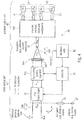
- Fig, 4 shows an example of an optical antenna 40 for a duplex link 400 formed by a transmit, Tx, beam 41 towards a partner optical antenna and a receive, Rx, beam 42 from the partner antenna.
- the optical antenna 40 may be comprising:
- the duplex link 400 may be formed by a transmit, Tx beam 41 towards a part of the antenna, and a receive, Rx, beam 42 from the partner antenna.
- the antenna 40 is also an example of an optical antenna for a duplex link 400 formed by a transmit, Tx, beam 41 towards a partner optical antenna and a receive, Rx, beam 42 from the partner antenna, the optical antenna 40 comprising:
- Fig. 4 shows a distal optical path 40".
- the distal optical path 40" may be on free-space.
- the distal optical path 40" may guide the duplex link 400.
- the duplex link may be formed by:
- the antenna 40 may comprise a proximal optical path 40'.
- the proximal optical path 40' may comprise, inter alia, a single-mode waveguide 43 (e.g., one single waveguide).
- light may be generated at one or more Tx sources 41' (e.g., photodiodes).
- Light may be directed to block 440, which may comprise equipment such as at least one duplexer, at least one switch, at least one filter, and/or at least one multiplexer.
- a single-mode waveguide 43 may collect light generated by the sources 41'.
- the Tx beam 41 generated by the at least one Tx source 41' is transmitted through the waveguide 43.
- the waveguide 43 may be a directional waveguide, which may transmit in a duplex way the transmit beam 41 while propagating, on the Rx direction, another beam (e.g., the Rx beam 42).
- the Tx beam 41 may be transmitted through the distal optical path 40".
- a collecting lens 442 may be, for example, placed downstream the waveguide 43 in the Tx direction.
- the collecting lens 442 may be the first element of the distal optical path 40" downstream to the proximal optical path 40'.
- the optical path may be in the free space (e.g., not within a waveguide).
- the rays of the Tx beam generated by the sources 41' may be expanded.
- the lens 442 may have the effect of rendering parallel, or approximately parallel, the rays of the Tx beam 41.
- the Tx beam 41 may be guided through the distal optical path 40" towards an aperture 444.
- the aperture 444 may be placed at the distal end of a telescope which is here not shown but may comprise an elongated (e.g., tubular cylinder guide%) path along which the Tx beam may be transmitted to external entities.
- a telescope instead of a telescope, simply an aperture may be provided.
- an Rx beam 42 (which is part of the duplex link 400) may be received from an external entity in the Rx direction (from the partner antenna into the antenna 40, and opposed with respect to the Tx direction).
- the Rx beam 42 may be irradiated so as to pass through the antenna aperture 444 and guided (e.g., along the telescope) through the distal optical path 40" to arrive to Rx receiver(s) 42'.
- the distal optical path 40" may be a duplex path, along which the Tx beam 41:
- the Tx beam 41 may be at a wavelength which is different from the wavelength of the Rx beam 42. In the same or alternative examples, the Tx beam 41 may have a polarization which is different from the polarization of the Rx beam.
- the lens 442 may have the inverse function than that it has in the Tx direction for the Tx beam 41.
- the Rx beam 42 (which may be understood as being formed by parallel or almost parallel rays upstream to the lens 442 in the Rx direction) may be collected so as to enter, for example, into the waveguide 43.
- the Tx beam 41 is directed from the proximal optical path 40' to the distal optical path 40
- the Rx 42 beam is directed from the distal optical path 40" to the proximal optical path 40' (and be directed towards the Rx receiver 42') simultaneously in the waveguide 43.
- the waveguide 43 may be a single-mode waveguide, which is a waveguide which only permits beams to be propagated according to one single reflection angle.
- Single-mode waveguides have are more performing than multi-mode waveguides.
- the Rx beam 42 may be propagated towards the at least one receiver or receivers 42' through the block 440, which may comprise at least one or a plurality of duplexers, and/or at least or a plurality of switches, and/or at least one or a plurality of filters, and/or at least one or a plurality of multiplexers.
- the optical antenna 40 may comprise a beam shaper 44 (such as a PAA beam shaper).
- the beam shaper 44 may be positioned in the distal optical path 40".
- the beam shaper 44 may shape the duplex propagation pattern of the duplex link 400.
- the beam shaper may force a first shape 50 of the pattern of the duplex link 400 (e.g., a uniform or circular shape, in some examples).
- the beam shaper 44 may, for example, shape the pattern of the link 400 to have a second shape 51 (e.g., an elongated or elliptical shape, for example).
- a multiplicity of patterns (which may also be different from the pattern 50 and 51) may also be chosen, in some examples.
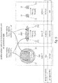
- FIG. 4a shows an example of the duplex link 400 (along a propagation axis Z) which may have a selectively uniform (e.g., circular) and/or elongated (e.g., elliptical) shape between a first antenna (e.g., associated to a first satellite 410) and a second antenna (e.g., associated to a second satellite 412).
- a first antenna e.g., associated to a first satellite 4
- a second antenna e.g., associated to a second satellite 412
- the cross section orthogonal to the axis Z of the duplex link 400 may have a uniform (e.g., circular or otherwise radially symmetrical) shape 50 and/or an elongated (e.g., elliptical) shape 51.
- elongated shapes may be used (e.g., a more elongated shape and a less elongated shape).
- the uniform (e.g., circular) shape may be chosen for the cases in which the PAA is zero or very closed to zero.
- Fig. 4a shows possible radiation pattern for reciprocal transmission with point-ahead angle (PAA).
- Fig. 5 shows different options for different shapes of the duplex link 400. These shapes are seen in a plane XY orthogonal to the direction of propagation Z of the duplex link 400.
- Fig. 5 shows a first pattern 50 in which the duplex link is uniform (e.g., symmetric, such as circular).
- a first pattern 500 may be shaped so as to enclose the partner antenna (e.g., satellite) position at an instant T 0 at which the Rx beam 42 has been generated.
- the pattern 500 may also enclose the satellite position at T 0 + ⁇ t, which is the instant at which the partner antenna (e.g., mounted on a satellite) will receive the beam which is currently generated.
- the first pattern 50 may be shaped so that both the position 52 and 53 are in the scope of the duplex link 400. Therefore, we may understand that the optical antenna 40 transmits a Tx beam 41 towards an area which is broader than strictly necessary (which would be only an area around the position 53). Further, the Rx beam 42 encompasses an area which is greater than the position 52 from which the photons are actually irradiated.
- the PAA has been of 50 ⁇ rad (but different angles may be possible).
- a duplex link actually encloses the whole PAA. If we imagine, for example, the PAA as an angle which has as vertex on the antenna 40 and is generated by two lines (a first line directed from the antenna 40 to the position 52 and a second line directed from the antenna 40 to the position 53), we may understand the PAA as an angle completely comprised within the scope of the duplex link 400.
- the design complexity of such a construction is low and the propagation loss is terms high.
- Fig. 5 also shows Option 2, according to which the beam pattern of the duplex link 400 is a pattern 51 which may have, for example, an elongated shape (e.g., elliptical).
- the shape of the pattern 51 may encompass both the position 52 of the partner antenna at instant T 0 and the position 53 of the partner antenna at instant T 0 + ⁇ t.
- the signal (among all the light irradiated by the partner antenna) actually received by the antenna 40 is the same in Option 1 and in Option 2.
- both positions 52 and 53 are within the patterns 500 and 51 and this means that no transmission will be lost.
- Option 2 requires much less transmission power. Accordingly, with Option 2 the propagation loss is reduced with respect to Option 1, despite a slight increase in the design complexity.
- Fig. 5 also shows an Option 3, according to which a non-duplex link Is used (e.g., as in Fig. 1 ).
- a Tx beam 14 is directed to the position 52, while a different beam 16 is directed to the position 53.
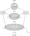
- Fig. 5a shows three examples of patterns 50, 51, and 51', according to examples, for the link 400 under Option 2.
- a pattern 50 may be obtained only where the PAA is 0 or approximately 0 (e.g., below a particular threshold, such as 5 ⁇ rad), e.g., when the positions 52 (at T 0 ) and 53 (at T 0 + ⁇ t) are basically coincident. For example, this is when the antenna 40 and the partner antenna are stationary with each other or when they only move along axis Z.
- the pattern 50 may be uniform in the plane XY, e.g. may have a radial symmetry (e.g., circular) around the propagation axis Z (orthogonal to Fig. 5a ).
- the pattern 50 may be substantially rounded, e.g., with the coincident positions 52 and 53 approximately or perfectly at the center of a circle formed by the pattern 50.
- the pattern 51 may be chosen when PAA increases (e.g., 50 ⁇ rad). In that case, the positions 52 and 53 are so far away that they would not be contained in the link 400.
- Another pattern 51' may be chosen, in examples, in case the PAA is further increased (e.g., 80 ⁇ rad).
- the pattern of the link 400 on the basis of the PAA, for example.
- the elongation may follow the direction of extension of the PAA (which scales with the relative speed of the partner antenna as observed by the antenna 40).
- the greater the PAA the greater the pattern (e.g., pattern 51' instead of pattern 51, and/or pattern 51 instead of pattern 50).
- the pattern may be increased (e.g., more elongated), e.g., from the pattern 50 to the pattern 51 or 51' (or from 51 to 51', for example).
- the antenna (40) may increase (e.g., elongate) the pattern (e.g., more elongated), e.g., from the pattern 50 to the pattern 51 or 51' (or from 51 to 51', for example).
- the elongation may be in a direction parallel to the direction of increase of the PAA (e.g., axis X), e.g., orthogonally to the axis Z of propagation of the link 400.
- the duplex link 400 between a first pattern and a second pattern (e.g., the first pattern may be 50 and the second 51 or 51'; the first pattern may be 51 and the second 51', and so on).
- Fig. 5b shows another example of shaping between a first pattern 510 (at instant To) and a second pattern 512 (at instant T 0 + ⁇ t).
- the first pattern 510 may be elongated along a direction which is the direction of modification of the PAA.
- a second pattern 512 may be chosen. For example, if the direction of the increase of the PAA is rotated (e.g., around the axis Z) of an angle ⁇ , it is possible to follow the evolution of the PAA by choosing the second pattern 512 (which is also rotated of ⁇ ).
- Fig. 6 shows an example of the beam shaper 44 which may be used to generate, and/or modify, and/or shape the pattern of the duplex link 400.
- the beam shaper 44 may comprise a dispersing optical unit 44a and/or a collecting optical unit 44b (e.g., as seen in the Tx direction, while having an opposite function in the Rx direction).
- the surfaces of lenses 44a and 44b which are in front of each other (facing to each other) are non-symmetrical, e.g., cylindrical.
- the cylindrical shape may prevent, for example, from a radial symmetry.
- the cylindrical shape may be such that, by cross-sectioning the lenses 44a and 44b along planes parallel to the plane XZ along which the lenses 44a and 44b are shown in Fig. 6 , the same shape of the cross section is obtained.
- the shapes of the surfaces of lenses 44a and 44b may be complementary, in the sense that, when they are superposed to each other (e.g., when lens 44a abuts on lens 44b), they force the lenses to be simple "pieces of glass" (or other material) which has, e.g., no effect in shaping the duplex link 400.
- the lenses 44a and 44b e.g., by virtue of the shape of their facing surfaces
- the elongation of the pattern may be controlled on the basis of the distance L between the lenses 44a and 44b. The greater L, the more elongated the shape.
- an elongated pattern (e.g., in the X direction) may be obtained,
- the beam shaper 44 may be configured to modify the distance L between the dispersing optical unit 44a and the collecting optical unit 44b under the control of an external controller to modify the shape of the duplex propagation pattern of the duplex link 400.
- the radial dimension of the pattern 50 or 51 is increased (e.g., the scope of the duplex link 400 is broader), while a reduction of the distance L reduces the elongation of the pattern 50 or 51.
- the example on the right in Fig. 6 permits to appreciate that, when the distance L is zero, a uniform (e.g., circular) shape is obtained.
- one distal surface of the lens 44a may be complementary to the shape of the lens 44b, so that, in case of the complementary surfaces abutting to each other, a uniform (e.g., circular) shape is caused.
- the particular shape of the lens 44a may cause the rays of the Tx beam 41 to diverge and the rays of the Rx beam 42 to become parallel. Further, the particular shape of the lens 44b may cause the rays of the Tx beam 41 to be collected or to become parallel, while the effect to the Rx beam 42 is to collect the back-propagating rays.
- the effect of the lenses 44a and 44b can be basically the same as a normal "piece of glass” (or another material).
- Another effect of the beam shaper 44 may be obtained by the shape of the lenses 44a and 44b. These lenses may have a shape which is not radially symmetrical and may cause the duplex propagation pattern to take different shapes (e.g., between the shape of the first pattern 50 and the shape of the second pattern 51). By controlling the rotation of the beam shaper 44 around the axis Z, different positions can be chosen which may generate different shapes, e.g. an elliptical shape and/or a circular shape. This effect is obtained by known optical techniques which permit to modify the shape of beams.
- the lenses 44a and 44b both modify the shape of the incoming Rx beam 42 and of the transmitted Tx beam 41 in a duplex way, as can be seen by the focal patterns and the far-field patterns shown in Fig. 6 .
- a focal pattern of the beams 41 and 42 is associated to the distal extremity of the waveguide 43.
- a controller 45 may adaptively shape the duplex propagation pattern of the duplex link 400 between the shape of the pattern 50 and the shape of the pattern 51 (other patterns are possible, for example, intermediate patterns), For example, the controller 45 may control the distance L between the lenses 44a and 44b. Hence, the controller 45 may be responsible for adaptively choosing the elongation (e.g., in direction X) of the duplex propagation pattern of the duplex link 400. The controller 45 may also control the shape of the duplex propagation pattern of the duplex link 400 by rotating the pattern as in Fig. 5b .
- the rotation of the lenses 44a and 44b may cause the modification of the shape of the pattern of the duplex link 400. If the lenses 44a and 44b are rotated jointly to each other (or, however, so as to take the same orientations at any instant), the effects of the lenses 44a and 44b will be the same, apart from rotating the elongation around the axis Z. For example, the rotation of the lenses 44a and 44b may permit the rotation from the pattern 510 to the pattern 512 in Fig. 5b .
- the beam shaper 44 is placed before an attachment to an external telescope (beam expander). In examples, the beam shaper 44 is completely independent from the telescope. In examples, the beam shaper 44 is capable of shaping and/or modifying the pattern of the duplex link 400 irrespective of the telescope. In examples, the beam shaper 44 is capable of shaping and/or modifying the pattern of the duplex link 400 even if the telescope is not moved. In examples, instead of a telescope a simple aperture may be provided.
- the controller 45 may be configured to choose the most appropriate shape for the pattern of the duplex link 400, e.g., using a feedback-based solution, e.g., based on positional data or data associated to the status of the antenna 40 and/or of the partner antenna.
- the controller 45 may exert its control on the basis of positional data 46.
- the positional data 46 may be either known a priori (e.g., on the basis of gravitational data), and stored in a storage unit, or obtained on the basis of a detector, such as a fine tracking system 448 (optional).
- controller 45 may be configured to adaptively shape the duplex propagation pattern so that the second pattern 51 is smaller than the first pattern 50.
- the controller 45 may be configured to adaptively shape the duplex propagation pattern so that at least one dimension of the first pattern 50 is smaller than that of the first pattern 51.
- the controller 45 may be configured to adaptively shape the duplex propagation pattern so that the second pattern 51 is more elongated than the first pattern 50.
- the controller 45 may be configured to adaptively shape the duplex propagation pattern so that the second pattern 51 is more elongated than the first pattern 50 in one first direction X (e.g., the direction of the trajectory of the partner antenna as observed by the antenna 40) and/or to have the same elongation of the first pattern 50 in one second direction Y (e.g., the direction orthogonal to X and Z).
- first direction X e.g., the direction of the trajectory of the partner antenna as observed by the antenna 40
- Y e.g., the direction orthogonal to X and Z
- the controller 45 may be configured to adaptively shape the duplex propagation pattern so that the second pattern 51 (or 51') have at least one greater dimension (e.g., along axis X) than that of the first pattern 50 (or 51).
- a method 110 is shown in Fig. 11 , which may illustrate operations of the controller 45 and/or of parts of the antenna 40.
- the status of the optical antenna 40 and/or of the partner antenna may be acquired by the controller 45.
- the status may comprise, inter alia: pointing error (error in positioning, which may be bound to the probability of localizing the partner antenna) and/or pointing function and/or setup mode and/or PAA.
- the controller may verify criteria on the status.
- the criteria on the status may condition the controller 45 to choose the most appropriate shape for the pattern of the duplex link 400.
- the controller 45 may actuate a control (e.g., by modifying parameters of the beam shaper 44, such as the distance between the lenses 44a and 44b and/or by rotating the lenses 44a and 44b around the optical axis).
- a control e.g., by modifying parameters of the beam shaper 44, such as the distance between the lenses 44a and 44b and/or by rotating the lenses 44a and 44b around the optical axis.
- the controller 45 is configured to base the criteria at least on the point-ahead angle, PAA, between the optical antenna 40 and the partner optical antenna, so as to be conditioned towards modifying the duplex propagation pattern:
- the shape of the duplex link 400 may be modified so that both the positions 52 and the position 53 are within the scope of the duplex link 400.
- the PAA is reduced, it is possible to modify the shape of the duplex link 400 again, and, in case the positions 52 and 53 coincide, to have a little, circular pattern 50, for example.
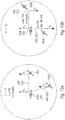
- the pattern of the duplex link 400 may be uniform and narrow (the communications of the satellite 1000 with the satellites 1002 and 1004 are not simultaneous: Fig. 10a is not meant as showing a real implementation but to only represent status of the antennas).
- Fig. 10b shows the satellite 1000 (on which the antenna 40 is mounted) in communication to the satellite 1004.
- the satellite 1000 and the satellite 1004 are and/or move in the same line but with different versus. Therefore, even in this case the PAA is equal to 0. Accordingly, even in this case the shape of the pattern of the duplex link 400 may be narrow and uniform (e.g., circular).
- it could be possible to increase the pattern of the duplex link 400 e.g., by elongating the pattern, e.g., from 50 to 51 or 51' or from 51 to 51').
- an increased diameter of a circular pattern would increase power loss, as a bigger area would be irradiated by the duplex link 400.
- the second, elongated (e.g., elliptical) pattern 51 may be chosen, provided that the second pattern 51 (or 51') also encloses the positions 52 and 53 of the satellite 1002. In this way, the propagation losses are reduced but the data received from the satellite 1002 and the data transmitted to it are notwithstanding provided.
- a criterion may therefore be that the greater the PAA, the more elongated the pattern of the duplex link 400, and/or vice versa.
- the pattern may be elongated in the direction of extension of the PAA, which is the direction on which the satellite 1002 moves (parallel to axis X in Fig. 5a ).
- the criterion may provide that, in case of rotation of the PAA around an axis Z (or in a plane XZ orthogonal to the axis Z), the duplex link 400 is rotated accordingly (e.g., by rotating the lenses 44a and 44b).
- controller 45 may be configured to base the criteria at least on the pointing error, so as to be conditioned towards modifying the duplex propagation pattern:
- the distance between the positions 52 and 53 and the border (e.g., circumferential or perimeter or border or boundary line) of the pattern 50 and/or of the pattern 51 may be defined to be less than the error tolerance.
- the shape of the pattern may be defined so as to ensure a communication which is error-tolerant.
- the errors in the direction Y in Fig. 5a are in general limited, in particular for high speed of the partner antenna (greater PAA).
- the errors in the direction of extension of the PAA may be bigger. Therefore, at higher speeds, an elliptical shape (or another non-uniform shape) elongated in the axis X (direction of the relative speed) appears to be appropriate, as it is possible to precisely localize the positions 52 and 53 along the direction of the relative movement (X).
- a broader pattern may be chosen.
- controller 45 may be configured to base its criteria at least on a pointing function and/or setup mode, so as to be conditioned towards modifying the duplex propagation pattern between:
- a pointing function it is possible to localize the partner antenna. This may be part of an initial procedure in which the position of the partner antenna is refined starting from a not accurate knowledge of the position of the partner antenna. For example, a rough localization may be based on a prior known data (e.g., based on gravitational data), for which a broad pattern for the duplex link 400 may be generated. For example, the first pattern 50 with an increased diameter may be chosen.
- a pattern with reduced shape and/or with an elliptical shape may be chosen.
- the beam shaper 44 on the basis of the status of the optical antenna and of the partner antenna, it is possible to condition the beam shaper 44 to modify the pattern of the duplex link 400 according to the most preferable shape among a plurality of possible shapes.
- an increased dimension and a decreased dimension e.g., on the basis of the probability of intercepting the position of the partner antenna and between a uniform (e.g., circular) shape and an elongated (e.g., elliptical) shape on the basis of positional data 46.
- the data 46 may be a priori known (e.g., derived from gravitational data of the satellites) and/or obtained by measurements.
- the criteria discussed above may also be composed with each other and/or the controller 45 may decide that one or more criteria are more relevant than other criteria.
- the controller 45 may decide that some criteria are more important than other ones, e.g., on the basis of the status. For example, at the initial pointing a particular criterion may be chosen, while, after the localization of the partner antenna, a different criterion may be used.
- the criteria may be composed with each other, e.g., by voting between different criteria. For example, by verifying three criteria it is acknowledged that two criteria condition the controller towards choosing the pattern 50 and one single criterion conditions the controller towards choosing the pattern 51, the controller 45 may finally decide to force the beam shaper 44 to shape the beam pattern to be as the patter 51.
- the voting may be weighted, in the sense that some criteria may be more important (e.g., more conditioning) than other criteria.
- a final rating is obtained on the basis of different state variables calculated from the different criteria. It is possible, for example, to sum different state variables derived from different criteria, and to compare the final rating with threshold(s). The comparison of the final rating with the threshold(s) will determine the pattern of the duplex link 400.
- Figs. 7-9 show examples of the proximal optical path 40.
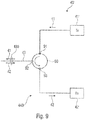
- Fig. 9 shows a transmit source 41' and a receive Rx source 42' which are optically connected to the duplex bidirectional waveguide 43.
- the duplex link 400 may be composed by the beams 41 and 42 in correspondence of a non-reciprocal optical element 90.
- the non-reciprocal optical element 90 may be, for example, an optical circulator.
- the non-reciprocal optical element 90 may be a device with a first connector 91, a second connector 92, and a third connector 93.
- a Tx beam input to the first connector 91 may be directed to the waveguide 43 through the second connector 92.
- An input for the waveguide 43 at the second connector 92 may be output through the third connector 93 towards the Rx receiver 42'.
- the bidirectional link 400 at the non-reciprocal optical element 90, so that the bidirectional link 400 is propagated and back-propagated through the bidirectional duplex waveguide 43.
- the Tx beam 41 in the transmit direction and the Rx beam 42 in the receive direction may take one single angle of propagation through the waveguide 43.
- a simple and straightforward, but highly performing, waveguide may be used.
- the duplex link 400 is truly bidirectional and single mode, as the rays do not take slightly different directions.
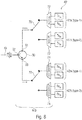
- Fig. 7 shows an example of proximal optical path which permits to switch between a first mode and a second mode.
- an antenna operating either as a type-1 antenna or a type-2 antenna (the type-1 antenna having a first polarization or wavelength in transmission and a second polarization or wavelength in reception, and the type-2 antenna having the second polarization or wavelength in transmission and the first polarization or transmission in reception).
- an operation as type-1 or type-2 may be selected by using a simple and straightforward optical switch 70.
- the switch 70 may be, for example, obtained by using a laser switch.
- the type-1 mode may be obtained, for example, by using one or more Tx sources 41'a and/or one or more Rx receivers 42'a.
- a type-1 Tx beam 41-1 may be input at the first connector 91 of the non-reciprocal optical element 90 (e.g circulator) and transmitted to the waveguide 43 to contribute to the duplex link 400-1.
- the duplex link 400-1 may comprise, in back-propagation, an Rx beam 42-2 which may be directed in duplex way to the second connector 92 of the non-reciprocal optical element 90.
- the non-reciprocal optical element 90 may redirect the type-1 Rx beam 42-2 towards the at least one receiver 42'a.
- the type-2 operations may be obtained by switching the switch 70 to different, type-2 Tx sources 41'b and different, type-2 Rx receivers 42'b. If the switch 70 is switched towards the type-2 elements, a type-2 duplex link 400-2 would be propagated and back-propagated at the waveguide 43 and the distal optical path 40'.
- the type-1 Tx sources 41'a may generate light at a first wavelength or polarization
- the type-2 Tx sources 41'b may generate light at a second wavelength or polarization.
- the wavelength of the light generated by the sources 41'a may have the same polarization or wavelength of the light transmitted to the type-2 Rx receivers 42'b, while the light generated by the type-2 sources 41'b may have the same wavelength or polarization of the type-1 receivers 41'a.
- FIG. 8 A variant of the example of Fig. 7 is provided by Fig. 8 , in which one single circulator and two optical switches 70 are used.
- multiplexers 72 and demultiplexers 74 may be used, e.g. for composing light from a plurality of different sources and/or for providing light to different receivers, respectively.
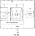
- Fig. 12 shows a schematic view of a satellite 412 or 1000 on which the optical antenna 40 is mounted.
- the optical antenna 40 may be a part of an optical communication unit 120 whose task is to operate communications with partner antennas, for permitting an application controller 124 to exchange data with the application controller of a partner antenna.
- the communication controller 122 may be configured to control the at least one Tx source 41' to generate Tx beams 41 according to a bitstream to be communicated to the partner antenna.
- the communication controller 122 may be configured to decode a bitstream, received from the partner antenna, on the basis of light decoded by the at least one Rx receiver 42'.
- the communication controller 122 may comprise, for example, a control unit 152 whose task is to generate and receive bitstreams to be transmitted and/or received to and/or from the partner antenna.
- the control unit 152 may be associated, for example, to the Tx source(s) 41' and the Rx receiver(s) 42' by means of an input/output, I/O, unit 150.
- the I/O unit 150 controls the Tx sources 41' so as to generate light in a way that carries information valuable for an application controller associated to the patent antenna.
- the input/output unit 150 is configured to obtain information carried by the Rx beam 42 and received by the optical communication unit(s) 42'.
- the communication controller 122 may also comprise an application interface 154 to transmit a bitstream obtained by decoding the signals receivers 42' and/or to receive data to be transmitted in the form of the Tx beam 41'.
- the application controller 124 therefore, may request the transmission of data and may make use of data decoded by the communication controller 122.
- the duplexing isolation of currently available circulators is about 60dB. This isolation could be seen as not being enough for high-speed (e.g. 10 Gbit/s) bidirectional inter-satellite links, where polarization or wavelength filters would have to be added.
- the demultiplexers 74 may permit to operate as filters for this purpose. Circulators alone could provide the necessary duplexing isolation for other optical links (e.g. with asymmetrical data rates).
- the waveguide 43 is a single-mode waveguide, it is possible to easily and reliably perform a setup mode and/or a pointing function.
- the use of the single-mode waveguide 43 permits the Tx beam 41 and the Rx beam 42 to have a common path. Therefore, for reciprocity (when the partner antenna is configured as the antenna 40), the power of the Rx beam is the same of the power of the Tx beam, and it is possible to know that the partner antenna is receiving the Tx beam 41 at the same power at which the antenna 40 receives the Rx beam 42.
- the partner antenna is tracked (and the partner antenna has tracked the antenna 40).
- the antenna 40 may therefore be configured to:
- the antenna 40 may, in addition or alternative:
- a setup or pointing function 132 may comprise, for example, a step 133 of elongating the pattern (e.g., to obtain the pattern 51) of the duplex link 400.
- detection step 134 light is obtained by the receiver(s) 42'.
- the iteration 136b reinitiates the step 133, to increase the elongation of the pattern of the duplex link 400 (e.g., to arrive at 51').
- Examples above refer to a method comprising: controlling the shape of a duplex propagation pattern 50, 51 of a duplex link 400 for an optical antenna 40 to enclose:
- the method may further comprise:
- Examples above refer to a method comprising a method for a duplex link 400 formed by a transmit, Tx, beam 41 towards a partner optical antenna and a receive, Rx, beam 42 from the partner antenna, along:
- non-transitory storage device storing instructions that, when executed by a processor, cause the processor to perform any of the steps of or any of the methods above and/or below and/or implement any of the components and/or any of the apparatus or systems below and/or above.
- examples may be implemented in hardware.
- the implementation may be performed using a digital storage medium, for example a floppy disk, a Digital Versatile Disc (DVD), a Blu-Ray Disc, a Compact Disc (CD), a Read-only Memory (ROM), a Programmable Read-only Memory (PROM), an Erasable and Programmable Read-only Memory (EPROM), an Electrically Erasable Programmable Read-Only Memory (EEPROM) or a flash memory, having electronically readable control signals stored thereon, which cooperate (or are capable of cooperating) with a programmable computer system such that the respective method is performed. Therefore, the digital storage medium may be computer readable.
- DVD Digital Versatile Disc
- CD Compact Disc
- ROM Read-only Memory
- PROM Programmable Read-only Memory
- EPROM Erasable and Programmable Read-only Memory
- EEPROM Electrically Erasable Programmable Read-Only Memory
- flash memory having electronically readable control signals stored thereon, which cooperate (or are capable of
- examples may be implemented as a computer program product with program instructions, the program instructions being operative for performing one of the methods when the computer program product runs on a computer.
- the program instructions may for example be stored on a machine readable medium,
- Examples comprise the computer program for performing one of the methods described herein, stored on a machine readable carrier.
- an example of method is, therefore, a computer program having a program instructions for performing one of the methods described herein, when the computer program runs on a computer.
- a further example of the methods is, therefore, a data carrier medium (or a digital storage medium, or a computer-readable medium) comprising, recorded thereon, the computer program for performing one of the methods described herein.
- the data carrier medium, the digital storage medium or the recorded medium are tangible and/or non-transitionary, rather than signals which are intangible and transitory.
- a further example comprises a processing unit, for example a computer, or a programmable logic device performing one of the methods described herein,
- a further example comprises a computer having installed thereon the computer program for performing one of the methods described herein.
- a further example comprises an apparatus or a system transferring (for example, electronically or optically) a computer program for performing one of the methods described herein to a receiver.
- the receiver may, for example, be a computer, a mobile device, a memory device or the like.
- the apparatus or system may, for example, comprise a file server for transferring the computer program to the receiver.
- a programmable logic device for example, a field programmable gate array
- a field programmable gate array may cooperate with a microprocessor in order to perform one of the methods described herein.
- the methods may be performed by any appropriate hardware apparatus.
- the context may be optical satellite communications.
- the focus may be on global satellite constellation, e.g., with many LEO satellites.
- This disclosure concerns, inter alia to the design of a bidirectional optical antenna which takes account of the point-ahead angle (PAA).
- PAA point-ahead angle
- Tx and Rx are combined beams go through the common path of the antenna telescope.
- a design with two separate telescopes (and apertures) for Tx and Rx would be too expensive.
- the Tx must point the beam ahead of the Rx beam direction to ensure reception by the partner satellite (see Fig. 1 ).
- the point-ahead angle (PAA) is not constant and depends on the positions and speed vectors of the antennas. For LEO satellites, the PAA typically ranges between 0 and 80 ⁇ rad.
- Optical satellite antennas for high-speed communication typically have a beam divergence of 5 to 20 ⁇ rad.
- the point-ahead angle for duplex transmission is implemented by separating/combining the Tx and Rx beams in free-space, using either polarization or wavelength (dichroic) division.
- Fig. 2 shows a typical optical design.
- the Tx and Rx beams are referred to with 16 and 14 respectively.
- the Rx beam power is generally split, one part being focused on the beam position sensor, another part being focused on the communication receiver.
- Rx beam separation is done by a simple beam splitter 25 (BS).
- the spot position sensor may be a camera or a quadrant detector (QD) 27 that provides a feedback to the fine steering mirror (FSM) 24 to correct the Rx beam direction.
- QD quadrant detector
- the difference in the direction of the Tx and Rx beams is controlled by the point-ahead mirror PAM 22.
- the PAM position is driven by the known orbit parameters.
- Fig. 3 shows a configuration where antennas have fixed division schemes for their duplexing, leading to antennas of "Type 1" and “Type 2" and leading to the impossibility of establishing links between antennas of the same type.
- the Tx /Rx wavelengths or polarizations must be swapped when a link with a different satellite is to be established.
- the conventional design features a free-space duplexing BS 23 (e.g. a cube of 2-cm side) that must be mechanically replaced. This task is critical and the design is demanding.
- optical antenna which may have one of the following combined properties:
- the examples provide design simplicity and networking flexibility.
- FIG. 4 An example is depicted in Fig. 4 .
- a basic idea of the new point-ahead implementation is to make the free-space antenna path 40" fully reciprocal by transmitting and receiving in the exact same (but opposite) directions Fig. 4 .
- the beam shaping mechanism 44 proposed in Fig. 6 can perform adaptive elongation of the beam profile in the PAA direction. It comprises two cylindrical lenses of collecting type and dispersal type, respectively. The distance between the two cylindrical lenses can be varied and the two lenses together can be rotated. Both lenses can be fitted together yielding a plane glass plate, leaving a small circular beam.
- Fig. 7 depicts implementation examples of the diagram box "duplexers, switches, filters and multiplexers" of Fig. 4 .
- single-mode waveguides In single-mode waveguides, the combining and separation of wavelengths and polarization is straightforward with standard components. More importantly, in single-mode waveguide, optical circulators are available. Multimode circulators, i.e. circulators for non-parallel beams (as when there is a PAA), are not available. Circulators are polarization- and wavelength-transparent. Therefore duplexing with circulators may not need polarization division or wavelength division and can free these resources.
- Multimode circulators i.e. circulators for non-parallel beams (as when there is a PAA)
- Circulators are polarization- and wavelength-transparent. Therefore duplexing with circulators may not need polarization division or wavelength division and can free these resources.
- duplexing isolation of currently available circulators is about 60dB. This isolation is not high enough for high-speed (e.g. 10 Gbit/s) bidirectional inter-satellite links, where polarization or wavelength filters would have to be added. However circulators alone could provide the necessary duplexing isolation for other optical links (e.g. with asymmetrical data rates).
- the switching of the antenna between Type-1 and Type-2 can be performed by only standard optical switches or simply by turning on or off some lasers. No large optical elements (e.g. beamsplitter cubes) must be mechanically replaced.
- antenna reciprocity leads to link reciprocity which means that the coupling loss from Antenna A to Antenna B is the same as from Antenna B to antenna A. This property is very useful for initial antenna alignment.
- An advantage of having a single fiber such as the waveguide 43 is that, in the absence of a point-ahead angle, the transmit and receive beams have a common path. Therefore, reciprocity of power transfer between transmitted and received beams is fully guaranteed.
- the elliptical or elongated beam, elongated in the PAA direction can overcome large pointing errors in the trajectory direction.
- the position of the counter-satellite is estimated from known orbit parameters and the beam is sent in the estimated direction.
- the satellite position error is in general larger in the trajectory direction, which is also the PAA direction. So, with an elongated beam that covers a wider position range, probability of mispointing is reduced.
- the elliptical beam profile can be adapted to the magnitude of the PAA.
- the Rx beam is detected as an elliptical spot beam.
- a quadrant detector can be used also to center elliptical beams.
- a variable offset can be implemented between the fiber position and the QD center.
- an optical antenna for a duplex link is formed by a transmit, Tx, beam towards a partner optical antenna and a receive, Rx, beam from the partner antenna, the optical antenna comprising:
- the controller is configured to adaptively shape the duplex propagation pattern between:
- the controller is configured to adaptively shape the duplex propagation pattern so that the area of the second pattern is greater than the area of the first pattern.
- the controller is configured to adaptively shape the duplex propagation pattern so that at least one dimension of the second pattern is greater than the same dimension of the first pattern.
- the controller is configured to adaptively shape the duplex propagation pattern so that the second pattern is more elongated than the first pattern.
- the controller is configured to base the criteria at least on the point-ahead angle, PAA, between the optical antenna and the partner optical antenna, so as to be conditioned towards modifying the duplex propagation pattern:
- the controller is configured to base the criteria at least on the pointing error, so as to be conditioned towards modifying the duplex propagation pattern:
- the controller is configured to base the criteria at least on a pointing function and/or setup mode, so as to be conditioned towards modifying the duplex propagation pattern:
- the controller is configured to shape the duplex propagation pattern to be more elongated in the direction of the segment between the first partner antenna position and the second partner antenna position and/or in the direction of the PAA.
- the controller is configured to shape the duplex propagation pattern to have an elliptical shape, the major axis parallel or adjacent to the distance between the first partner antenna position and the second partner antenna position.
- the controller is configured to shape the duplex propagation pattern to have a circular shape in case of the PAA being smaller than a predetermined threshold.
- the beam shaper comprises a dispersing optical unit and a collecting optical unit, and the beam shaper is configured to modify the distance between the dispersing optical unit and the collecting optical unit under the control of the controller to modify the shape of the duplex propagation pattern.
- the beam shaper comprises a dispersing optical unit and a collecting optical unit, and the beam shaper is configured to modify the distance between the dispersing optical unit and the collecting optical unit under the control of the controller to elongate the shape of the duplex propagation pattern.
- the beam shaper comprises a dispersing optical unit and a collecting optical unit, and at least one of the dispersing optical unit and the collecting optical unit is a cylindrical lens.
- the beam shaper comprises at least one rotatable optical unit with a non-circularly-symmetric shape adapted to modify the duplex propagation pattern in accordance with the orientation of the at least one rotatable optical unit, and the beam shaper is configured to rotate the at least one rotatable optical unit under the control of the controller to modify the shape and/or orientation of the duplex propagation pattern.
- the beam shaper comprises at least one rotatable optical unit with a non-circularly-symmetric shape adapted to modify the duplex propagation pattern in accordance with the orientation of the at least one rotatable optical unit, and the beam shaper is configured to rotate the at least one rotatable optical unit under the control of the controller to rotate the duplex propagation pattern.
- the beam shaper is placed before an attachment to an external telescope.
- the waveguide is a duplex waveguide.
- the waveguide is a single-mode waveguide.
- the proximal waveguide path comprises a non-reciprocal optical element including a first connector, a second connector, and a third connector, so as to direct:
- an optical antenna for a duplex link formed by a transmit, Tx, beam towards a partner optical antenna and a receive, Rx, beam from the partner antenna comprises:
- the optical antenna is configured as in any of the first to twentieth aspects.
- the non-reciprocal optical element is a circulator.
- the optical antenna further comprises:
- the optical antenna further comprises: a wavelength filter and/or polarization filter downstream to the at least one Tx source and/or upstream to the at least one receiver.
- the optical antenna further comprises:
- the waveguide is a single-mode waveguide
- the antenna is configured to:
- the optical antenna is configured to:
- an optical communication unit comprises:
- a satellite comprising the optical communication unit of the twenty-ninth aspect and/or an optical antenna of any of the first to twenty-eighth aspects.
- a system comprises the optical antenna according to any of the first to twenty-eighth aspects and the partner antenna, the partner antenna being configured as an optical antenna according to any of the first to twenty-ninth aspects.
- a method comprises: controlling the shape of a duplex propagation pattern of a duplex link for an optical antenna to enclose:
- the method of the thirty-second aspect further comprises:
- a thirty-fourth aspect relates to a method for a duplex link formed by a transmit, Tx, beam towards a partner optical antenna and a receive, Rx, beam from the partner antenna, along:
- a thirty-fifth aspect relates to the method of any of the thirty-second or thirty-third or thirty-fourth aspects, using the equipment defined in any of the first to thirty-first aspects.
- a thirty-sixth aspect relates to a non-transitory storage device storing instructions that, when executed by a processor, cause the processor to perform any of the steps of or any of the methods of the thirty-first to thirty-fourth aspects and/or implement any of the components and/or any of the apparatus or systems of any of the first to thirty-first aspects.
Landscapes
- Physics & Mathematics (AREA)
- Engineering & Computer Science (AREA)
- Computer Networks & Wireless Communication (AREA)
- Signal Processing (AREA)
- Electromagnetism (AREA)
- General Physics & Mathematics (AREA)
- Astronomy & Astrophysics (AREA)
- Optics & Photonics (AREA)
- Optical Communication System (AREA)
Abstract
Description
- Examples relates to optical communications between optical antennas and related methods.
- Examples relate to waveguide-based duplexing with point-ahead angle (PAA) implementation.
-
Fig. 1 shows an example of optical communication between afirst satellite 10 and asecond satellite 12 according to the prior art. The communications may be performed through optical beams, i.e., small bundles of optical rays which are sent, e.g. through an optical antenna, in the direction of the receiver. Thesatellites first satellite 10 transmits a firstoptical beam 14 to thesecond satellite 12 while thesecond satellite 12 transmits a secondoptical beam 16 to thefirst satellite 10. Thebeams first satellite 10 For performing its transmission, thesecond satellite 12 shall guess the future position of thefirst satellite 12 to direct its beam; otherwise the information would be lost. In general terms, thesecond satellite 12 must be aware of the presence of a point-ahead angle (PAA), which is an angle between the receivedbeam 14 and the transmittedbeam 16. It is often possible to approximate the PAA to the value 2V/c (c being light velocity). The values of PAA vary with the distance and the speed of the satellites, but it is not infrequent to refer to angles between 0 and 80 µrad (microradians). (The dimensions inFig. 1 may be exaggerated for the sake of explanation.) -
Fig. 2 shows an example ofoptical antenna 20 according to the prior art (e.g., mounted in thesatellite 12 and useful to transmit thebeam 14 and transmit the beam 16). Theoptical antenna 20 comprises at least a waveguide portion formed by aRx waveguide 18 and aTx waveguide 19. Theoptical antenna 20 comprises several other elements which are part of a free-space portion. - The
optical antenna 20 comprises a Tx path and a Rx path. In the Tx path there are provided theTx waveguide 19, a converginglens 21, a point-ahead mirror (PAM) 22, a polarization or dichroic beam splitter, BS, 23, afine steering mirror 24, and afurther telescope aperture 29. Theelements set 250, which refers to the Tx path which is different from the free-space Rx path, making the free-space path non-reciprocal. In the Rx path there are provided thetelescope aperture 29, theFSM 24, the polarization ordichroic BS 23, apositioning BS 25, which bifurcates the Rx path between a measuring path (including aconverging lens 26 and a quadrant detector 27) and a communication path (including a converginglens 28 and the Rx waveguide 18). - In order to obtain simultaneous, duplex communications, different polarizations and/or different wavelengths may be used. For example, the polarizations and/or wavelengths of
beams dichroic BS 23 is the element that duplexes the Rx path and the Tx path. As seen in the Tx path (in the Tx propagation direction from the Tx waveguide to the telescope), the polarization ordichroic BS 23 filters specific wavelengths (or polarizations) from the upstream side 23a to the downstream side 23b. As seen in the Rx path (in the Rx propagation direction from the telescope to the Rx waveguide), the polarization ordichroic BS 23 filters the receivedbeam 14 from the upstream side 23b to thedownstream side 23c. The result is that: - in the interspace between the polarization or
dichroic BS 23 and theFSM 24, both thebeams - in the Tx path upstream (in the Tx propagation direction) from the
Tx waveguide 19 to the polarization or dichroicBS 23, (ideally) only the transmittedbeam 16 propagates; - in the Rx path downstream (in the Rx propagation direction) from the polarization or dichroic
BS 23 to theRx 18, ideally only the receivedbeam 14 propagates. - In general terms, the polarization or
dichroic BS 23 is a passive optical element, whose structure is normally a cube comprising two triangular glass prisms. The side dimension may be close to 20 mm. As such, the polarization ordichroic BS 23 is not an "intelligent" component, and uniquely filters wavelengths or polarizations which are a priori determined. - This has brought to the necessity of defining different "antenna types" for different optical antennas, following the particular polarization or
dichroic BS 23 that is mounted in a particular antenna.Fig. 3 shows an example of a so-called "type-1" antenna mounted on afirst satellite 31, a so-called "type-2" antenna mounted on asecond satellite 32, and another type-1 antenna mounted on a third satellite 33. A type-1 antenna can only transmit a beam at a first polarization (Pol.1) or wavelength (λ1) but only receive a beam at a second polarization (Pol.2) or wavelength (λ2) (e.g., in the Tx path, at the upstream side 23a of theBS 23, the beam is only at the first polarization or wavelength; in the Rx path, at thedownstream side 23c, the beam is, at least in ideal conditions, only at the second polarization or wavelength). A type-2 antenna is complementary to the type-1 antenna: it only receives a beam at the first polarization (Pol.1) or wavelength (λ1) but only transmits a beam at the second polarization (Pol.2) or wavelength (λ2) (e.g., in the Tx path, at the upstream side 23a of theBS 23, the light is only at the second polarization or wavelength; in the Rx path, at thedownstream side 23c, the light is at least in ideal conditions only at the first polarization or wavelength). Accordingly, even if two antennas of different type (e.g., 31 with 32; or 32 with 33) may simultaneously communicate with each other, antennas of the same type (e.g., 31 with 33) cannot bidirectionally communicate: theBS 23 of each antenna would not be able to discriminate the received beam from the transmitted beam as they would have the same wavelength or polarization. - In the prior art, efforts have been made in the sense of trying to use a plurality of polarization or dichroic BSs (each BS discriminating different wavelengths or polarizations), which may be robotically substituted with each other in the same position. If we imagine, for example, an array of multiple polarization or
dichroic BSs 23 displaced one after the other in the direction exiting from the plane ofFig. 2 , we may conceive an automated mechanism which places a selected BS in the position of theBS 23. Hence, each antenna may become type-selectable. In other examples, it is possible to use rotational mechanisms to rotate the polarization or dichroicBSs 23 for changing between a type-1 and a type-2. However, the mechanisms for performing these operations are complicated, as they require the use of precise electric motors, drives, actuators, positioners, and other elements with normally reduced reliability and which, when failed, may not be easily repaired. This is a major concern for narrow and uninhabited environments such satellites, where maintenance on the fly is not possible. - Also the effects of the power consumption required by the actuators positioning elements such as the polarization or
dichroic BSs 23 are to be taken into account. - With reference to
Fig. 2 , theFSM 24 permits to finely position the receivedbeam 14 and the transmitted beam 16 (e.g., between a first position, indicated by a continuous line, and a second position, indicated by a dotted line). Notwithstanding, thebeams Fig. 2 as being coincident fromaperture 29 to BS side 23b, actually take slightly different angles, as they require to be directed according to different directions (e.g., with a PAA which may be e.g., 80 µrad). ThePAM 22 may be rotated (e.g., around an axis exiting from the plane ofFig. 2 ) in accordance with the satellite positional data and/or the PAA. Accordingly, the direction of the transmittedbeam 16 differs from that of the receivedbeam 14 in such a way to permit thesecond satellite 12 to point to thefirst satellite 10. - Such an operation is not easily performed, however. At first, also the rotation of the
PAM 22 requires non-straightforward mechanisms, which tend to reduce reliability of the antenna, - Further, with reference to
Fig. 1 , for the control devices of thesecond satellite 12, it is not extremely straightforward to actually guess the position of thefirst satellite 10 and to finely transmit thesecond beam 16 in the direction at which the telescope aperture of the antenna of thefirst satellite 10 will be positioned. In fact, while the estimated satellite motion is also subjected to errors (pointing errors such as calculation errors, measurement errors, resolution errors, etc.), the beams shall necessarily have a pattern with reduced thickness (the thickness being, for example, a diameter of the cross section of the beam perpendicular to its trajectory) for the sake of decreasing the propagation loss. Therefore, an easy and reliable pointing of the beam comes at the expenses of power coupling efficiency, while the increase of efficiency tendentially requires high pointing precision. - The above notwithstanding, it is also preferable to reduce the bulkiness of the equipment, both for the purposes of increasing simplicity and for that of reducing the costs. Therefore, the option of using, in one single satellite, a Rx antenna different from a Tx is normally discarded.
- In general terms, the reduction of the number of bulky components and mechanical parts is appreciated for optical antenna in satellites. In an antenna such as that of
Fig. 2 , however, the different optical paths, implied by the use of the polarization ordichroic BS 23, cause an unrequested redundancy of the optical devices, and in particular of voluminous ones. Notwithstanding, it is not possible to use one single converging lens, and it is necessary to use twolenses - Also preferable would be the use of one single waveguide instead of both the
Rx waveguide 18 and the Tx waveguide. In order to achieve such a result, however, some optical means should be necessary, to mix the Tx beam upstream with the converginglens 21 and the Rx beam downstream with thelens 28. Moreover, by virtue of the different angles taken by the twobeams PAM 22, the twobeams - A difficulty is represented by the fact that, at the setup (pointing function), it is normally difficult to exactly retrieve the partner antenna (mounted on satellite 10), as it is difficult to recognize if the received light is the light directly obtained from the partner antenna. In order to cope with such an inconvenient, complicated calibration techniques have been developed. These calibration techniques are quite difficult to be implemented, as it is difficult to finely adjust the modes of the
Tx waveguide 19 and theRx waveguide 18. Basically, it is difficult to guarantee that, when the Rx waveguide receives light, also the light transmitted by theTx waveguide 19 is actually received by the partner antenna. -
-
Fig. 1 shows a system according to the prior art. -
Fig. 2 shows an optical antenna according to the prior art. -
Fig. 3 shows a communication schema according to the prior art. -
Fig. 4 shows an optical antenna according to examples above and/or below. -
Fig. 4a shows a system comprising the optical antenna ofFig. 4 . -
Fig. 5 shows different radiation patterns for bidirectional beams according to examples in comparison with other radiation patterns. -
Fig. 5a and5b show different radiation patterns for bidirectional beams according to examples. -
Fig. 6 shows a beam shaper according to examples above and/or below. -
Figs. 7-9 show components for an antenna according to examples above and/or below. -
Figs. 10a and 10b show different status for systems with optical antennas. -
Fig. 11 shows a method of operating according to examples above and/or below. -
Fig. 12 shows a schematic view of a satellite according to examples above and/or below. -
Fig. 13 shows an example of setup mode or pointing function. - There is here disclosed an optical antenna for a duplex link formed by a transmit, Tx, beam towards a partner optical antenna and a receive, Rx, beam from the partner antenna, the optical antenna comprising:
- a proximal optical path including a bidirectional waveguide for a duplex propagation of the duplex link from at least one Tx source of the Tx beam and towards at least one receiver of the Rx beam;
- a distal duplex optical path for a duplex propagation of the duplex link from and towards the partner optical antenna;
- a beam shaper positioned in the distal optical path to shape the duplex propagation pattern of the duplex link; and
- a controller to control the beam shaper to adaptively shape the duplex propagation pattern to enclose:
- a first partner antenna position of the partner antenna at the instant of transmission of the Rx beam; and
- a second antenna position of the partner antenna at the instant of reception of the Tx beam.
- According to an aspect, the controller may be configured to adaptively shape the duplex propagation pattern between:
- a first pattern; and
- a second pattern different from the first pattern,
- wherein the controller is configured to modify the duplex propagation pattern from the first pattern to the second pattern and/or vice versa on the basis of criteria on status of the optical antenna and/or the partner optical antenna.
- According to an aspect, the controller may be configured to adaptively shape the duplex propagation pattern so that the area of the second pattern is greater than the area of the first pattern.
- According to an aspect, the controller may be configured to adaptively shape the duplex propagation pattern so that at least one dimension of the second pattern is greater than the same dimension of the first pattern.
- According to an aspect, the controller may be configured to adaptively shape the duplex propagation pattern so that the second pattern is more elongated than the first pattern.
- According to an aspect, the controller may be configured to base the criteria at least on the point-ahead angle, PAA, between the optical antenna and the partner optical antenna, so as to be conditioned towards modifying the duplex propagation pattern:
- from the first pattern to the second pattern when the PAA is increased, and/or
- from the second pattern to the first pattern (50) when the PAA is reduced; and/or
- so as to elongate the duplex propagation pattern in the direction of extension of the PAA; and/or
- so as to reduce the elongation of the duplex propagation pattern in case of reduction of the PAA and/or to increase the elongation of the duplex propagation pattern in case of increase of the PAA.
- According to an aspect, the controller may be configured to base the criteria at least on the pointing error, so as to be conditioned towards modifying the duplex propagation pattern:
- from the second pattern to the first pattern when the pointing error is reduced, and/or
- from the first pattern to the second pattern when the pointing error is increased, and/or
- so as to elongate the duplex propagation pattern in case of increased pointing error; and/or
- so as to reduce the elongation of the duplex propagation pattern in case of decreased pointing error.
- According to an aspect, the controller may be configured to base the criteria at least on a pointing function and/or setup mode, so as to be conditioned towards modifying the duplex propagation pattern:
- from the second pattern to the first pattern at the conclusion of the pointing function and/or setup mode, and/or
- from the first pattern to the second pattern at the start of the pointing function and/or setup mode; and/or
- to elongate the duplex propagation pattern for the pointing function and/or setup mode; and/or
- to reduce the elongation of the duplex propagation pattern at a normal operation mode.
- According to an aspect, the controller may be configured to shape the duplex propagation pattern to be more elongated in the direction of the segment between the first partner antenna position and the second partner antenna position and/or in the direction of the PAA.
- According to an aspect, the controller may be configured to shape the duplex propagation pattern to have an elliptical shape, the major axis parallel or adjacent to the distance between the first partner antenna position and the second partner antenna position.
- According to an aspect, the controller may be configured to shape the duplex propagation pattern to have a circular shape in case of the PAA being smaller than a predetermined threshold.
- According to an aspect, the beam shaper may comprise a dispersing optical unit and a collecting optical unit,
wherein the beam shaper is configured to modify the distance between the dispersing optical unit and the collecting optical unit under the control of the controller to modify the shape of the duplex propagation pattern. - According to an aspect, the beam shaper may comprise a dispersing optical unit and a collecting optical unit,
wherein the beam shaper is configured to modify the distance between the dispersing optical unit and the collecting optical unit under the control of the controller to elongate the shape of the duplex propagation pattern. - According to an aspect, the beam shaper may comprise a dispersing optical unit and a collecting optical unit,
wherein at least one of the dispersing optical unit and the collecting optical unit is a cylindrical lens. - According to an aspect, the beam shaper may comprise at least one rotatable optical unit with a non-circularly-symmetric shape adapted to modify the duplex propagation pattern in accordance with the orientation of the at least one rotatable optical unit,
wherein the beam shaper is configured to rotate the at least one rotatable optical unit under the control of the controller to modify the shape and/or orientation of the duplex propagation pattern. - According to an aspect, the beam shaper may comprise at least one rotatable optical unit with a non-circularly-symmetric shape adapted to modify the duplex propagation pattern in accordance with the orientation of the at least one rotatable optical unit,
wherein the beam shaper is configured to rotate the at least one rotatable optical unit under the control of the controller to rotate the duplex propagation pattern. - According to an aspect, the beam shaper may be placed before an attachment to an external telescope.
- According to an aspect, the waveguide may be a duplex waveguide.
- According to an aspect, the waveguide may be a single-mode waveguide.
- According to an aspect, the proximal waveguide path may comprise a non-reciprocal optical element including a first connector, a second connector, and a third connector, so as to direct:
- light input from the first connector to the second connector; and
- light input from the second connector to the third connector,
- wherein the first connector is configured to receive the Tx beam from at least one Tx source, the second connector is optically communicating with the bidirectional waveguide, and the third connector is configured to output the Rx beam.
- There is also disclosed an optical antenna for a duplex link formed by a transmit, Tx, beam towards a partner optical antenna and a receive, Rx, beam from the partner antenna, the optical antenna comprising:
- a proximal optical path including a bidirectional waveguide for duplex propagation of the Tx beam from at least one Tx source and of the Rx beam towards at least one receiver; and
- a distal duplex free-space optical path for duplex propagation of the Tx beam towards the partner optical antenna and the Rx beam from the partner optical antenna,
- wherein the proximal waveguide path comprises a non-reciprocal optical element including a first connector, a second connector, and a third connector, so as to direct:
- light input from the first connector to the second connector; and
- light input from the second connector to the third connector,
- wherein the first connector is configured to receive the Tx beam (41from at least one Tx source, the second connector is optically communicating with the bidirectional waveguide, and the third connector is configured to output the Rx beam.
- According to an aspect, the optical antenna may be configured as examples above and/or below.
- According to an aspect, the non-reciprocal optical element may be a circulator.
- According to an aspect, the optical antenna may comprise:
- a first Tx source(s) and a second Tx source(s) and/or a first receiver(s) and a second receiver(s), and
- at least one optical switch to switch between the first Tx source(s) and the second Tx source(s) and/or between first receiver(s) and the second receiver(s),
- wherein the first Tx source(s) and the second Tx source(s) are configured to generate light at different wavelength ranges and/or polarization ranges, and/or
- the first receiver(s) and the second receiver(s) are configured to receive and/or detect light at different wavelength ranges and/or polarization ranges.
- According to an aspect, the optical antenna may comprise:
a wavelength filter and/or polarization filter downstream to the at least one Tx source and/or upstream to the at least one receiver. - According to an aspect, the optical antenna may comprise:
- a wavelength multiplexer and/or polarization multiplexer downstream to the at least one Tx source and/or
- wavelength demultiplexer and/or polarization demultiplexer upstream to the at least one receiver, to separate different wavelengths and/or polarization ranges.
- According to an aspect, the waveguide may be a single-mode waveguide, the antenna being configured to:
- perform a pointing function and/or setup mode in which the Tx beam is transmitted;
- check the detection of the Rx beam from the partner antenna;
- determine the end of the pointing function and/or setup mode in case of detection of an Rx beam.
- According to an aspect, the optical antenna may be configured to:
- elongate or increase at least one dimension of the duplex propagation pattern of the duplex link in case of absence of detection of the Rx beam; and/or
- reduce at least one dimension or render uniform the duplex propagation pattern in case of detection of the Rx beam.
- There is also disclosed an optical communication unit comprising:
- an optical antenna according to any of the examples above and/or below; and
- a communication controller configured to:
- control the at least one Tx source to generate Tx beams according to a bitstream to be communicated to the partner antenna;
- decode a bitstream transmitted from the partner antenna on the basis of light decoded by the at least one receiver.
- There is also disclosed a satellite comprising any of the optical communication units below and/or above and/or any optical antenna as above and/or below.
- There is also disclosed a system comprising the optical antenna according to any of the examples above and/or below and the partner antenna, the partner antenna being configured as any of the examples above and/or below.
- There is disclosed a method comprising:
controlling the shape of a duplex propagation pattern of a duplex link for an optical antenna to enclose: - a first partner antenna position of a partner antenna at the instant of transmission of the Rx beam of the duplex link; and
- a second antenna position of the partner antenna at the instant of reception of the Tx beam.
- According to an aspect, the method may comprise;
- adaptively shaping the duplex propagation pattern between:
- a first pattern; and
- a second pattern different from the first pattern; and
- modifying the duplex propagation pattern from the first pattern to the second pattern and/or vice versa on the basis of criteria on status of the optical antenna and/or the partner optical antenna.
- adaptively shaping the duplex propagation pattern between:
- There is disclosed a method for a duplex link formed by a transmit, Tx, beam towards a partner optical antenna and a receive, Rx, beam from the partner antenna, along:
- a proximal optical path including a bidirectional waveguide for duplex propagation of the Tx beam from at least one Tx source and of the Rx beam towards at least one receiver;
- a distal duplex free-space optical path for duplex propagation of the Tx beam towards the partner optical antenna and the Rx beam from the partner optical antenna;
- wherein method comprises:
directing, through a non-reciprocal optical element including a first connector, a second connector, and a third connector:- light input from the first connector to the second connector; and
- light input from the second connector to the third connector,
- wherein the first connector is configured to receive the Tx beam from at least one Tx source, the second connector is optically communicating with the bidirectional waveguide, and the third connector Is configured to output the Rx beam.
- A method as above or below may use any of the equipment defined above and/or below.
- There is disclosed a non-transitory storage device storing instructions that, when executed by a processor, cause the processor to perform any of the steps of or any of the methods above/or below and/or implement any of the components and/or any of the apparatus or systems above and/or below.
-
Fig, 4 shows an example of anoptical antenna 40 for aduplex link 400 formed by a transmit, Tx,beam 41 towards a partner optical antenna and a receive, Rx,beam 42 from the partner antenna. Theoptical antenna 40 may be comprising: - a proximal optical path 40' including a
bidirectional waveguide 43 for a duplex propagation of theduplex link 400 from at least one Tx source 41' of theTx beam 41 and towards at least one receiver (or receptor) 42' of theRx beam 42; - a distal duplex
optical path 40" for a duplex propagation of theduplex link 400 from and towards the partner optical antenna; - a
beam shaper 44 positioned in the distaloptical path 40" to shape theduplex propagation pattern duplex link 400; and - a
controller 45 to control thebeam shaper 44 to adaptively shape theduplex propagation pattern - a first partner antenna position of the partner antenna at the instant of transmission of the
Rx beam 42; and - a second antenna position of the partner antenna at the instant of reception of the
Tx beam 41.
- a first partner antenna position of the partner antenna at the instant of transmission of the
- The
duplex link 400 may be formed by a transmit,Tx beam 41 towards a part of the antenna, and a receive, Rx,beam 42 from the partner antenna. - The
antenna 40 is also an example of an optical antenna for aduplex link 400 formed by a transmit, Tx,beam 41 towards a partner optical antenna and a receive, Rx,beam 42 from the partner antenna, theoptical antenna 40 comprising: - a proximal optical path 40' including a
bidirectional waveguide 43 for duplex propagation of theTx beam 41 from at least one Tx source 41' and of theRx beam 42 towards at least one receiver 42'; - a distal duplex free-space
optical path 40" for duplex propagation of theTx beam 41 towards the partner optical antenna and theRx beam 42 from the partner optical antenna; - wherein the proximal waveguide path 40' comprises a non-reciprocal
optical element 90 including (with reference toFigs. 7-9 ) afirst connector 91, asecond connector 92, and athird connector 93, so as to direct:- light input from the
first connector 91 to thesecond connector 92; and - light input from the
second connector 92 to thethird connector 93, - wherein the
first connector 91 is configured to receive theTx beam 41 from at least one Tx source 41', thesecond connector 92 is optically communicating with thebidirectional waveguide 43, and thethird connector 93 is configured to output theRx beam 42.
- light input from the
-
Fig. 4 shows a distaloptical path 40". The distaloptical path 40" may be on free-space. The distaloptical path 40" may guide theduplex link 400. The duplex link may be formed by: - the
Tx beam 41 from at least one light source 41' towards the partner antenna (such as the antenna of a satellite of a base station); and - the
Rx beam 42, which may receive light (e.g., photons) from the remote antenna (such as the partner antenna) which is to be received by at least one receiver 42'. - The
antenna 40 may comprise a proximal optical path 40'. The proximal optical path 40' may comprise, inter alia, a single-mode waveguide 43 (e.g., one single waveguide). As shown inFig. 4 , light may be generated at one or more Tx sources 41' (e.g., photodiodes). Light may be directed to block 440, which may comprise equipment such as at least one duplexer, at least one switch, at least one filter, and/or at least one multiplexer. In the Tx direction (from the sources 41' to the aperture), a single-mode waveguide 43 may collect light generated by the sources 41'. TheTx beam 41 generated by the at least one Tx source 41' is transmitted through thewaveguide 43. Notably, thewaveguide 43 may be a directional waveguide, which may transmit in a duplex way the transmitbeam 41 while propagating, on the Rx direction, another beam (e.g., the Rx beam 42). - In the Tx direction, the
Tx beam 41 may be transmitted through the distaloptical path 40". A collectinglens 442 may be, for example, placed downstream thewaveguide 43 in the Tx direction. The collectinglens 442 may be the first element of the distaloptical path 40" downstream to the proximal optical path 40'. For example, from the distal extremity of the waveguide 43 (e.g., optical fibre), the optical path may be in the free space (e.g., not within a waveguide). From thewaveguide 43 to thelens 442, the rays of the Tx beam generated by the sources 41' may be expanded. In examples, thelens 442 may have the effect of rendering parallel, or approximately parallel, the rays of theTx beam 41. TheTx beam 41 may be guided through the distaloptical path 40" towards anaperture 444. Theaperture 444 may be placed at the distal end of a telescope which is here not shown but may comprise an elongated (e.g., tubular cylinder guide...) path along which the Tx beam may be transmitted to external entities. In examples, instead of a telescope, simply an aperture may be provided. - As can be seen from
Fig. 4 , an Rx beam 42 (which is part of the duplex link 400) may be received from an external entity in the Rx direction (from the partner antenna into theantenna 40, and opposed with respect to the Tx direction). TheRx beam 42 may be irradiated so as to pass through theantenna aperture 444 and guided (e.g., along the telescope) through the distaloptical path 40" to arrive to Rx receiver(s) 42'. - The distal
optical path 40" may be a duplex path, along which the Tx beam 41: - is generated by the source(s) 41';
- propagates through:
- ∘ the proximal optical path 40';
- ∘ the distal
optical path 40"; - ∘ the free space after the
aperture 444; and
- reachs an external entity (partner antenna).
- Simultaneously, the Rx beam 42:
- is irradiated from the external entity;
- is propagated through:
- ∘ the
antenna aperture 444; - ∘ the distal
optical path 40", - ∘ the proximal optical path 40'; and
- ∘ the
- reaches the Rx at least one receiver or receivers 42'.
- In examples, the
Tx beam 41 may be at a wavelength which is different from the wavelength of theRx beam 42. In the same or alternative examples, theTx beam 41 may have a polarization which is different from the polarization of the Rx beam. - In the Rx direction, the
lens 442 may have the inverse function than that it has in the Tx direction for theTx beam 41. For example, the Rx beam 42 (which may be understood as being formed by parallel or almost parallel rays upstream to thelens 442 in the Rx direction) may be collected so as to enter, for example, into thewaveguide 43. In examples, while theTx beam 41 is directed from the proximal optical path 40' to the distaloptical path 40", theRx 42 beam is directed from the distaloptical path 40" to the proximal optical path 40' (and be directed towards the Rx receiver 42') simultaneously in thewaveguide 43. - The
waveguide 43 may be a single-mode waveguide, which is a waveguide which only permits beams to be propagated according to one single reflection angle. Single-mode waveguides have are more performing than multi-mode waveguides. - In the Rx direction, the
Rx beam 42 may be propagated towards the at least one receiver or receivers 42' through theblock 440, which may comprise at least one or a plurality of duplexers, and/or at least or a plurality of switches, and/or at least one or a plurality of filters, and/or at least one or a plurality of multiplexers. - In examples, the
optical antenna 40 may comprise a beam shaper 44 (such as a PAA beam shaper). Thebeam shaper 44 may be positioned in the distaloptical path 40". Thebeam shaper 44 may shape the duplex propagation pattern of theduplex link 400. In examples, the beam shaper may force afirst shape 50 of the pattern of the duplex link 400 (e.g., a uniform or circular shape, in some examples). Thebeam shaper 44 may, for example, shape the pattern of thelink 400 to have a second shape 51 (e.g., an elongated or elliptical shape, for example). A multiplicity of patterns (which may also be different from thepattern 50 and 51) may also be chosen, in some examples.Fig. 4a shows an example of the duplex link 400 (along a propagation axis Z) which may have a selectively uniform (e.g., circular) and/or elongated (e.g., elliptical) shape between a first antenna (e.g., associated to a first satellite 410) and a second antenna (e.g., associated to a second satellite 412). As may be seen fromFigs. 4 and4a , in the space, as it is possible to understand, the cross section orthogonal to the axis Z of theduplex link 400 may have a uniform (e.g., circular or otherwise radially symmetrical)shape 50 and/or an elongated (e.g., elliptical)shape 51. In other examples, only elongated shapes may be used (e.g., a more elongated shape and a less elongated shape). In examples, the uniform (e.g., circular) shape may be chosen for the cases in which the PAA is zero or very closed to zero. - An example is provided by
Fig. 4a , which shows possible radiation pattern for reciprocal transmission with point-ahead angle (PAA). -
Fig. 5 shows different options for different shapes of theduplex link 400. These shapes are seen in a plane XY orthogonal to the direction of propagation Z of theduplex link 400. -
Fig. 5 shows afirst pattern 50 in which the duplex link is uniform (e.g., symmetric, such as circular). - With reference to
Option 1, afirst pattern 500 may be shaped so as to enclose the partner antenna (e.g., satellite) position at an instant T0 at which theRx beam 42 has been generated. Thepattern 500 may also enclose the satellite position at T0 + Δt, which is the instant at which the partner antenna (e.g., mounted on a satellite) will receive the beam which is currently generated. Hence, thefirst pattern 50 may be shaped so that both theposition duplex link 400. Therefore, we may understand that theoptical antenna 40 transmits aTx beam 41 towards an area which is broader than strictly necessary (which would be only an area around the position 53). Further, theRx beam 42 encompasses an area which is greater than theposition 52 from which the photons are actually irradiated. - As can be seen from
Option 1, in the time interval between the instants T0 and T0 + Δt, the PAA has been of 50 µrad (but different angles may be possible). Hence, a duplex link actually encloses the whole PAA. If we imagine, for example, the PAA as an angle which has as vertex on theantenna 40 and is generated by two lines (a first line directed from theantenna 40 to theposition 52 and a second line directed from theantenna 40 to the position 53), we may understand the PAA as an angle completely comprised within the scope of theduplex link 400. As explained inFig. 5 , the design complexity of such a construction is low and the propagation loss is terms high. -
Fig. 5 also showsOption 2, according to which the beam pattern of theduplex link 400 is apattern 51 which may have, for example, an elongated shape (e.g., elliptical). The shape of thepattern 51 may encompass both theposition 52 of the partner antenna at instant T0 and theposition 53 of the partner antenna at instant T0 + Δt. - Notably, the signal (among all the light irradiated by the partner antenna) actually received by the
antenna 40 is the same inOption 1 and inOption 2. The same applies for the useful light (among all the light transmitted by the antenna 40) which actually reaches the partner antenna. In fact, bothpositions patterns patterns Option 2 requires much less transmission power. Accordingly, withOption 2 the propagation loss is reduced with respect toOption 1, despite a slight increase in the design complexity. -
Fig. 5 also shows anOption 3, according to which a non-duplex link Is used (e.g., as inFig. 1 ). As can be seen, aTx beam 14 is directed to theposition 52, while adifferent beam 16 is directed to theposition 53. - Notwithstanding, this option is too complicated to be carried out even though if its propagation loss would be reduced.
-
Fig. 5a shows three examples ofpatterns link 400 underOption 2. - A
pattern 50 may be obtained only where the PAA is 0 or approximately 0 (e.g., below a particular threshold, such as 5 µrad), e.g., when the positions 52 (at T0) and 53 (at T0 + Δt) are basically coincident. For example, this is when theantenna 40 and the partner antenna are stationary with each other or when they only move along axis Z. Thepattern 50 may be uniform in the plane XY, e.g. may have a radial symmetry (e.g., circular) around the propagation axis Z (orthogonal toFig. 5a ). Thepattern 50 may be substantially rounded, e.g., with thecoincident positions pattern 50. - The
pattern 51 may be chosen when PAA increases (e.g., 50 µrad). In that case, thepositions link 400. - Another pattern 51' may be chosen, in examples, in case the PAA is further increased (e.g., 80 µrad).
- Basically, it is possible to elongate the pattern of the
link 400 on the basis of the PAA, for example. The elongation may follow the direction of extension of the PAA (which scales with the relative speed of the partner antenna as observed by the antenna 40). - In examples, the greater the PAA, the greater the pattern (e.g., pattern 51' instead of
pattern 51, and/orpattern 51 instead of pattern 50). - In addition or alternative, it may be possible to increase the pattern (and/or to increase the elongation) when the pointing error is increased.
- This may occur, for example, during a pointing function and/or setup mode, e.g., when the partner antenna is not in sight and its precise direction/position must be acquired. In order to increase the probability of finding (localizing) the partner antenna, the pattern may be increased (e.g., more elongated), e.g., from the
pattern 50 to thepattern 51 or 51' (or from 51 to 51', for example). - Another example is when the distance between the antenna (40) and the partner antenna is decreased. In that case, the pointing error is in general increased. In order to reduce the probability of losing the partner antenna, the antenna (40) may increase (e.g., elongate) the pattern (e.g., more elongated), e.g., from the
pattern 50 to thepattern 51 or 51' (or from 51 to 51', for example). In general, the elongation may be in a direction parallel to the direction of increase of the PAA (e.g., axis X), e.g., orthogonally to the axis Z of propagation of thelink 400. - It is possible to define a plurality of patterns (more than three ones), which may be varied, for example, on the basis of criteria on the antenna (40) and on the partner antenna (e.g., criteria on the status). It is therefore proposed to shape the
duplex link 400 between a first pattern and a second pattern (e.g., the first pattern may be 50 and the second 51 or 51'; the first pattern may be 51 and the second 51', and so on). -
Fig. 5b shows another example of shaping between a first pattern 510 (at instant To) and a second pattern 512 (at instant T0+Δt). Thefirst pattern 510 may be elongated along a direction which is the direction of modification of the PAA. When the direction of the modification of the PAA is modified, asecond pattern 512 may be chosen. For example, if the direction of the increase of the PAA is rotated (e.g., around the axis Z) of an angle Ω, it is possible to follow the evolution of the PAA by choosing the second pattern 512 (which is also rotated of Ω). - It is to be noted that elongating (as in
Fig. 5a ) the shape of the pattern in one single direction (e.g., X) is preferable and more efficient than simply increasing the diameter of the pattern (as it would be withOpinion 1 ofFig. 5 ). In fact, by intelligently elongating the pattern along one single direction, propagation loss is maintained low. A mere comparison between thepattern 51 ofOption 2 and thepattern 500 ofOption 1 inFig. 5 permits to appreciate that Option 2 (as well as all the patterns shown inFigs. 5a and5b ) require a smaller shape thanOption 2, without any loss in the information transmitted and/or received. -
Fig. 6 shows an example of thebeam shaper 44 which may be used to generate, and/or modify, and/or shape the pattern of theduplex link 400. Thebeam shaper 44 may comprise a dispersingoptical unit 44a and/or a collectingoptical unit 44b (e.g., as seen in the Tx direction, while having an opposite function in the Rx direction). - In examples, the surfaces of
lenses lenses lenses Fig. 6 , the same shape of the cross section is obtained. - The shapes of the surfaces of
lenses lens 44a abuts onlens 44b), they force the lenses to be simple "pieces of glass" (or other material) which has, e.g., no effect in shaping theduplex link 400. In examples, thelenses lenses - As may be seen in
Fig. 6 , for L>0, an elongated pattern (e.g., in the X direction) may be obtained, In examples, a rounded (e.g., circular)pattern 50 may be obtained, for example, when L=0. - The
beam shaper 44 may be configured to modify the distance L between the dispersingoptical unit 44a and the collectingoptical unit 44b under the control of an external controller to modify the shape of the duplex propagation pattern of theduplex link 400. - In examples, if the distance L is increased, the radial dimension of the
pattern duplex link 400 is broader), while a reduction of the distance L reduces the elongation of thepattern Fig. 6 permits to appreciate that, when the distance L is zero, a uniform (e.g., circular) shape is obtained. - As can be seen from
Fig. 6 , one distal surface of thelens 44a may be complementary to the shape of thelens 44b, so that, in case of the complementary surfaces abutting to each other, a uniform (e.g., circular) shape is caused. - As can be seen from
Fig. 6 , the particular shape of thelens 44a may cause the rays of theTx beam 41 to diverge and the rays of theRx beam 42 to become parallel. Further, the particular shape of thelens 44b may cause the rays of theTx beam 41 to be collected or to become parallel, while the effect to theRx beam 42 is to collect the back-propagating rays. - In examples, when the distance L is equal to 0, no effect or a negligible effect is caused on the optical shape of the propagation beams, When L is equal to 0, the effect of the
lenses - Another effect of the
beam shaper 44 may be obtained by the shape of thelenses first pattern 50 and the shape of the second pattern 51). By controlling the rotation of thebeam shaper 44 around the axis Z, different positions can be chosen which may generate different shapes, e.g. an elliptical shape and/or a circular shape. This effect is obtained by known optical techniques which permit to modify the shape of beams. - Notably, the
lenses incoming Rx beam 42 and of the transmittedTx beam 41 in a duplex way, as can be seen by the focal patterns and the far-field patterns shown inFig. 6 . As can be seen fromFig. 6 , a focal pattern of thebeams waveguide 43. - As shown in
Fig. 4 , acontroller 45 may adaptively shape the duplex propagation pattern of theduplex link 400 between the shape of thepattern 50 and the shape of the pattern 51 (other patterns are possible, for example, intermediate patterns), For example, thecontroller 45 may control the distance L between thelenses controller 45 may be responsible for adaptively choosing the elongation (e.g., in direction X) of the duplex propagation pattern of theduplex link 400. Thecontroller 45 may also control the shape of the duplex propagation pattern of theduplex link 400 by rotating the pattern as inFig. 5b . - In examples, the rotation of the
lenses duplex link 400. If thelenses lenses lenses pattern 510 to thepattern 512 inFig. 5b . Accordingly, it is possible to control the direction (orientation) of the elongation of the pattern of theduplex link 400 in a plane XY orthogonal to the optical axis, This control may be exerted by thecontroller 45 which may determine the orientation of the pattern on the basis of the direction of relative motion of the partner antenna, for example. - In examples, the
beam shaper 44 is placed before an attachment to an external telescope (beam expander). In examples, thebeam shaper 44 is completely independent from the telescope. In examples, thebeam shaper 44 is capable of shaping and/or modifying the pattern of theduplex link 400 irrespective of the telescope. In examples, thebeam shaper 44 is capable of shaping and/or modifying the pattern of theduplex link 400 even if the telescope is not moved. In examples, instead of a telescope a simple aperture may be provided. - Basically, the
controller 45 may be configured to choose the most appropriate shape for the pattern of theduplex link 400, e.g., using a feedback-based solution, e.g., based on positional data or data associated to the status of theantenna 40 and/or of the partner antenna. - In examples, the
controller 45 may exert its control on the basis ofpositional data 46. Thepositional data 46 may be either known a priori (e.g., on the basis of gravitational data), and stored in a storage unit, or obtained on the basis of a detector, such as a fine tracking system 448 (optional). - In examples, the
controller 45 may be configured to adaptively shape the duplex propagation pattern so that thesecond pattern 51 is smaller than thefirst pattern 50. - In examples, the
controller 45 may be configured to adaptively shape the duplex propagation pattern so that at least one dimension of thefirst pattern 50 is smaller than that of thefirst pattern 51. - In examples, the
controller 45 may be configured to adaptively shape the duplex propagation pattern so that thesecond pattern 51 is more elongated than thefirst pattern 50. - In examples, the
controller 45 may be configured to adaptively shape the duplex propagation pattern so that thesecond pattern 51 is more elongated than thefirst pattern 50 in one first direction X (e.g., the direction of the trajectory of the partner antenna as observed by the antenna 40) and/or to have the same elongation of thefirst pattern 50 in one second direction Y (e.g., the direction orthogonal to X and Z). - In examples, the
controller 45 may be configured to adaptively shape the duplex propagation pattern so that the second pattern 51 (or 51') have at least one greater dimension (e.g., along axis X) than that of the first pattern 50 (or 51). - A
method 110 is shown inFig. 11 , which may illustrate operations of thecontroller 45 and/or of parts of theantenna 40. Atblock 112, the status of theoptical antenna 40 and/or of the partner antenna may be acquired by thecontroller 45. The status may comprise, inter alia: pointing error (error in positioning, which may be bound to the probability of localizing the partner antenna) and/or pointing function and/or setup mode and/or PAA. - At
step 114, the controller may verify criteria on the status. The criteria on the status may condition thecontroller 45 to choose the most appropriate shape for the pattern of theduplex link 400. Atstep 116, thecontroller 45 may actuate a control (e.g., by modifying parameters of thebeam shaper 44, such as the distance between thelenses lenses duplex link 400 and to adapt it to the current status of theantenna 40 and of the partner antenna. Some examples of control are discussed here. - In examples, the
controller 45 is configured to base the criteria at least on the point-ahead angle, PAA, between theoptical antenna 40 and the partner optical antenna, so as to be conditioned towards modifying the duplex propagation pattern: - from the first pattern 50 (or 51) to the second pattern 51 (or 51', or 512) when the PAA is increased, and/or
- from the second pattern 51 (or 51') to the first pattern 50 (or 51, or 510) when the PAA is reduced.
- Accordingly, when the PAA increases (e.g., on the basis of an increased relative speed of the partner antenna), the shape of the
duplex link 400 may be modified so that both thepositions 52 and theposition 53 are within the scope of theduplex link 400. When the PAA is reduced, it is possible to modify the shape of theduplex link 400 again, and, in case thepositions circular pattern 50, for example. - It is in general preferable to elongate the shape of the pattern of the
duplex link 400 in the direction of the relative motion of the partner antenna (which is the direction according to which the PAA extends, and is parallel to axis X inFigs. 4a and5 ).Fig. 10a represents asatellite 1000 carrying thepresent antenna 40 and asatellite 1002 on which the partner antenna is mounted. Both thesatellites duplex link 400 may be extremely narrow and uniform (e.g., circular). The same applies to thesatellite 1004 which moves at the same speed (V1 = V2) of thesatellite 1000. Therefore, even for thesatellite 1004, the pattern of theduplex link 400 may be uniform and narrow (the communications of thesatellite 1000 with thesatellites Fig. 10a is not meant as showing a real implementation but to only represent status of the antennas). -
Fig. 10b shows the satellite 1000 (on which theantenna 40 is mounted) in communication to thesatellite 1004. In this case, thesatellite 1000 and thesatellite 1004 are and/or move in the same line but with different versus. Therefore, even in this case the PAA is equal to 0. Accordingly, even in this case the shape of the pattern of theduplex link 400 may be narrow and uniform (e.g., circular). - The situation is different for the communication between the
satellite 1000 and the satellite 1002: as the relative motion between thesatellites duplex link 400. For example, it could be possible to increase the pattern of the duplex link 400 (e.g., by elongating the pattern, e.g., from 50 to 51 or 51' or from 51 to 51'). Notably, an increased diameter of a circular pattern, as inOption 1 ofFig. 5 , would increase power loss, as a bigger area would be irradiated by theduplex link 400. However, it has been noted that, in this case, instead of the firstuniform pattern 500, the second, elongated (e.g., elliptical) pattern 51 (or 51') may be chosen, provided that the second pattern 51 (or 51') also encloses thepositions satellite 1002. In this way, the propagation losses are reduced but the data received from thesatellite 1002 and the data transmitted to it are notwithstanding provided. - In general terms, a criterion may therefore be that the greater the PAA, the more elongated the pattern of the
duplex link 400, and/or vice versa. The pattern may be elongated in the direction of extension of the PAA, which is the direction on which thesatellite 1002 moves (parallel to axis X inFig. 5a ). - The criterion may provide that, in case of rotation of the PAA around an axis Z (or in a plane XZ orthogonal to the axis Z), the
duplex link 400 is rotated accordingly (e.g., by rotating thelenses - In examples, the
controller 45 may be configured to base the criteria at least on the pointing error, so as to be conditioned towards modifying the duplex propagation pattern: - from a second pattern (e.g., 51 or 51') to a first pattern (e.g., 50 or 51) (e.g., from a more elongated to a less elongated or circular shape) when the pointing error is reduced, and/or
- from a first pattern 50 (or 51) to a second pattern 51 (or 51') (e.g., from a less elongated to a more elongated or circular shape) when the pointing error is increased.
- It has been noted, in fact, that when the pointing error risks to be big, a greater shape may be used. By virtue of the increased localization error, it is possible that the partner antenna is not exactly at
positions Option 1 ofFig. 5 ) is not reached. Therefore, even if the pattern is elongated, efficiency is maintained. - According to examples, however, the distance between the
positions pattern 50 and/or of thepattern 51 may be defined to be less than the error tolerance. In this case, the shape of the pattern may be defined so as to ensure a communication which is error-tolerant. - The errors in the direction Y in
Fig. 5a (perpendicular to the axis X parallel to the extension of the PAA) are in general limited, in particular for high speed of the partner antenna (greater PAA). The errors in the direction of extension of the PAA (parallel to axis X) may be bigger. Therefore, at higher speeds, an elliptical shape (or another non-uniform shape) elongated in the axis X (direction of the relative speed) appears to be appropriate, as it is possible to precisely localize thepositions - Additionally or alternatively, the
controller 45 may be configured to base its criteria at least on a pointing function and/or setup mode, so as to be conditioned towards modifying the duplex propagation pattern between: - a more elongated shape (e.g., 51 or 51') when the pointing function and/or setup mode is to be started and/or
- a less elongated shape (e.g., 50 or 51) when the pointing function and/or setup mode has been concluded (e.g., in normal operation).
- On the basis of a pointing function, it is possible to localize the partner antenna. This may be part of an initial procedure in which the position of the partner antenna is refined starting from a not accurate knowledge of the position of the partner antenna. For example, a rough localization may be based on a prior known data (e.g., based on gravitational data), for which a broad pattern for the
duplex link 400 may be generated. For example, thefirst pattern 50 with an increased diameter may be chosen. Once the position of the partner antenna is localized (e.g., on the basis of data obtained by the fine tracking system 448), a pattern with reduced shape and/or with an elliptical shape may be chosen. - Hence, on the basis of the status of the optical antenna and of the partner antenna, it is possible to condition the
beam shaper 44 to modify the pattern of theduplex link 400 according to the most preferable shape among a plurality of possible shapes. - In particular, it is possible to choose between an increased dimension and a decreased dimension, e.g., on the basis of the probability of intercepting the position of the partner antenna and between a uniform (e.g., circular) shape and an elongated (e.g., elliptical) shape on the basis of
positional data 46. Thedata 46 may be a priori known (e.g., derived from gravitational data of the satellites) and/or obtained by measurements. - The criteria discussed above may also be composed with each other and/or the
controller 45 may decide that one or more criteria are more relevant than other criteria. Thecontroller 45 may decide that some criteria are more important than other ones, e.g., on the basis of the status. For example, at the initial pointing a particular criterion may be chosen, while, after the localization of the partner antenna, a different criterion may be used. - The criteria may be composed with each other, e.g., by voting between different criteria. For example, by verifying three criteria it is acknowledged that two criteria condition the controller towards choosing the
pattern 50 and one single criterion conditions the controller towards choosing thepattern 51, thecontroller 45 may finally decide to force thebeam shaper 44 to shape the beam pattern to be as thepatter 51. In examples, the voting may be weighted, in the sense that some criteria may be more important (e.g., more conditioning) than other criteria. In examples, instead of voting, a final rating is obtained on the basis of different state variables calculated from the different criteria. It is possible, for example, to sum different state variables derived from different criteria, and to compare the final rating with threshold(s). The comparison of the final rating with the threshold(s) will determine the pattern of theduplex link 400. -
Figs. 7-9 show examples of the proximaloptical path 40.Fig. 9 shows a transmit source 41' and a receive Rx source 42' which are optically connected to the duplexbidirectional waveguide 43. As can be seen fromFig. 9 , theduplex link 400 may be composed by thebeams optical element 90. The non-reciprocaloptical element 90 may be, for example, an optical circulator. The non-reciprocaloptical element 90 may be a device with afirst connector 91, asecond connector 92, and athird connector 93. A Tx beam input to thefirst connector 91 may be directed to thewaveguide 43 through thesecond connector 92. An input for thewaveguide 43 at thesecond connector 92 may be output through thethird connector 93 towards the Rx receiver 42'. - Accordingly, it is possible to generate the
bidirectional link 400 at the non-reciprocaloptical element 90, so that thebidirectional link 400 is propagated and back-propagated through thebidirectional duplex waveguide 43. By virtue of the operation of the non-reciprocal optical element, theTx beam 41 in the transmit direction and theRx beam 42 in the receive direction may take one single angle of propagation through thewaveguide 43. Hence, there is no need for a multi-mode waveguide. Therefore, a simple and straightforward, but highly performing, waveguide may be used. - In comparison to the device of
Fig. 2 (prior art), there is no need for both of theRx waveguide 18 andTx waveguide 19 and for thelenses waveguide 43 and in the subsequent distaloptical path 40", theduplex link 400 is truly bidirectional and single mode, as the rays do not take slightly different directions. -
Fig. 7 shows an example of proximal optical path which permits to switch between a first mode and a second mode. For example it is possible to obtain an antenna operating either as a type-1 antenna or a type-2 antenna (the type-1 antenna having a first polarization or wavelength in transmission and a second polarization or wavelength in reception, and the type-2 antenna having the second polarization or wavelength in transmission and the first polarization or transmission in reception). - As can be seen from
Fig. 7 , an operation as type-1 or type-2 may be selected by using a simple and straightforwardoptical switch 70. Theswitch 70 may be, for example, obtained by using a laser switch. The type-1 mode may be obtained, for example, by using one or more Tx sources 41'a and/or one or more Rx receivers 42'a. A type-1 Tx beam 41-1 may be input at thefirst connector 91 of the non-reciprocal optical element 90 (e.g circulator) and transmitted to thewaveguide 43 to contribute to the duplex link 400-1. The duplex link 400-1 may comprise, in back-propagation, an Rx beam 42-2 which may be directed in duplex way to thesecond connector 92 of the non-reciprocaloptical element 90. The non-reciprocaloptical element 90 may redirect the type-1 Rx beam 42-2 towards the at least one receiver 42'a. The type-2 operations may be obtained by switching theswitch 70 to different, type-2 Tx sources 41'b and different, type-2 Rx receivers 42'b. If theswitch 70 is switched towards the type-2 elements, a type-2 duplex link 400-2 would be propagated and back-propagated at thewaveguide 43 and the distal optical path 40'. For example, the type-1 Tx sources 41'a may generate light at a first wavelength or polarization, while the type-2 Tx sources 41'b may generate light at a second wavelength or polarization. The same applies to the Rx sources 42'a and 42'b. In examples, the wavelength of the light generated by the sources 41'a may have the same polarization or wavelength of the light transmitted to the type-2 Rx receivers 42'b, while the light generated by the type-2 sources 41'b may have the same wavelength or polarization of the type-1 receivers 41'a. - Accordingly, operations such as those between the
antennas Fig. 3 may be performed. However, contrary to the prior art, there is no need for modifying the position of a beam splitter as in the prior art (Fig. 2 ) and it is not necessary to use different polarization of dichroic BSs when it is necessary to move from a type-1 mode to a type-2 mode. Instead of actuators switched to modify the position of the one or more beam splitters (Fig. 2 ), we simply have anoptical switch 70 which may operate without mechanical complications and with acceptable reliability. - A variant of the example of
Fig. 7 is provided byFig. 8 , in which one single circulator and twooptical switches 70 are used. In the implementations,multiplexers 72 anddemultiplexers 74 may be used, e.g. for composing light from a plurality of different sources and/or for providing light to different receivers, respectively. -
Fig. 12 shows a schematic view of asatellite optical antenna 40 is mounted. Theoptical antenna 40 may be a part of anoptical communication unit 120 whose task is to operate communications with partner antennas, for permitting anapplication controller 124 to exchange data with the application controller of a partner antenna. Thecommunication controller 122 may be configured to control the at least one Tx source 41' to generate Tx beams 41 according to a bitstream to be communicated to the partner antenna. Thecommunication controller 122 may be configured to decode a bitstream, received from the partner antenna, on the basis of light decoded by the at least one Rx receiver 42'. Thecommunication controller 122 may comprise, for example, acontrol unit 152 whose task is to generate and receive bitstreams to be transmitted and/or received to and/or from the partner antenna. Thecontrol unit 152 may be associated, for example, to the Tx source(s) 41' and the Rx receiver(s) 42' by means of an input/output, I/O,unit 150. The I/O unit 150 controls the Tx sources 41' so as to generate light in a way that carries information valuable for an application controller associated to the patent antenna. The input/output unit 150 is configured to obtain information carried by theRx beam 42 and received by the optical communication unit(s) 42'. Thecommunication controller 122 may also comprise anapplication interface 154 to transmit a bitstream obtained by decoding the signals receivers 42' and/or to receive data to be transmitted in the form of the Tx beam 41'. Theapplication controller 124, therefore, may request the transmission of data and may make use of data decoded by thecommunication controller 122. - The duplexing isolation of currently available circulators is about 60dB. This isolation could be seen as not being enough for high-speed (e.g. 10 Gbit/s) bidirectional inter-satellite links, where polarization or wavelength filters would have to be added. For this purpose, the
demultiplexers 74 may permit to operate as filters for this purpose. Circulators alone could provide the necessary duplexing isolation for other optical links (e.g. with asymmetrical data rates). - However, even without filters, at bitrates of maximum than 1 Gbits/s, a proper duplex isolation is guaranteed.
- In examples, and in particular when the
waveguide 43 is a single-mode waveguide, it is possible to easily and reliably perform a setup mode and/or a pointing function. In fact, in case of PAA=0, the use of the single-mode waveguide 43 permits theTx beam 41 and theRx beam 42 to have a common path. Therefore, for reciprocity (when the partner antenna is configured as the antenna 40), the power of the Rx beam is the same of the power of the Tx beam, and it is possible to know that the partner antenna is receiving theTx beam 41 at the same power at which theantenna 40 receives theRx beam 42. When the Tx beam is therefore received at the setup mode or pointing function, the partner antenna is tracked (and the partner antenna has tracked the antenna 40). - The
antenna 40 may therefore be configured to: - perform a pointing function and/or setup mode In which the
Tx beam 41 is transmitted; - check the detection of the
Rx beam 42 from the partner antenna; - determine the end of the pointing function and/or setup mode in case of detection of an
Rx beam 42. - The
antenna 40 may, in addition or alternative: - elongate or increase at least one dimension of the duplex propagation pattern of the
duplex link 400 in case of absence of detection of theRx beam 42; and/or - reduce at least one dimension or render uniform the duplex propagation pattern in case of detection of the
Rx beam 42. - An example of a
method 130 is shown inFig. 13 . A setup or pointingfunction 132 may comprise, for example, astep 133 of elongating the pattern (e.g., to obtain the pattern 51) of theduplex link 400. Atdetection step 134, light is obtained by the receiver(s) 42'. At 135 it is verified whether theRx beam 42 is obtained from the partner antenna: if no (136), the setup or pointing function is cycled byiteration 136a to reinitiate anew detection step 134. Alternatively, theiteration 136b reinitiates thestep 133, to increase the elongation of the pattern of the duplex link 400 (e.g., to arrive at 51'). If at 135 it is acknowledged (137) that theRx beam 42 is obtained (i.e., the partner antenna is in sight), at 138 elongation of the pattern is reduced (e.g., to 50, in case PAA=0, or to a less elongated pattern) and theRx beam 42 is tracked. - Examples above refer to a method comprising:
controlling the shape of aduplex propagation pattern duplex link 400 for anoptical antenna 40 to enclose: - a first
partner antenna position 52 of a partner antenna at the instant of transmission of theRx beam 42 of theduplex link 400; and - a
second antenna position 53 of the partner antenna at the instant of reception of theTx beam 41. - The method may further comprise:
- adaptively shaping the
duplex propagation pattern - a
first pattern 50; and - a
second pattern 51 different from thefirst pattern 50; and
- a
- modifying the
duplex propagation pattern first pattern 50 to thesecond pattern 51 and/or vice versa on the basis of criteria on status of theoptical antenna 40 and/or the partner optical antenna. - Examples above refer to a method comprising a method for a
duplex link 400 formed by a transmit, Tx,beam 41 towards a partner optical antenna and a receive, Rx,beam 42 from the partner antenna, along: - a proximal optical path 40' including a
bidirectional waveguide 43 for duplex propagation of theTx beam 41 from at least one Tx source 41' and of theRx beam 42 towards at least one receiver 42'; - a distal duplex free-space
optical path 40" for duplex propagation of theTx beam 41 towards the partner optical antenna and theRx beam 42 from the partner optical antenna; - wherein method comprises
directing, through a non-reciprocaloptical element 90 including a first connector 91), a second connector 92), and a third connector 93):- light input from the
first connector 91 to the second connector 92); and - light input from the
second connector 92 to the third connector 93), - wherein the
first connector 91 is configured to receive theTx beam 41 from at least one Tx source 41', thesecond connector 92 is optically communicating with thebidirectional waveguide 43, and thethird connector 93 is configured to output theRx beam 42.
- light input from the
- It is also disclosed a non-transitory storage device storing instructions that, when executed by a processor, cause the processor to perform any of the steps of or any of the methods above and/or below and/or implement any of the components and/or any of the apparatus or systems below and/or above.
- Depending on certain implementation requirements, examples may be implemented in hardware. The implementation may be performed using a digital storage medium, for example a floppy disk, a Digital Versatile Disc (DVD), a Blu-Ray Disc, a Compact Disc (CD), a Read-only Memory (ROM), a Programmable Read-only Memory (PROM), an Erasable and Programmable Read-only Memory (EPROM), an Electrically Erasable Programmable Read-Only Memory (EEPROM) or a flash memory, having electronically readable control signals stored thereon, which cooperate (or are capable of cooperating) with a programmable computer system such that the respective method is performed. Therefore, the digital storage medium may be computer readable.
- Generally, examples may be implemented as a computer program product with program instructions, the program instructions being operative for performing one of the methods when the computer program product runs on a computer. The program instructions may for example be stored on a machine readable medium,
- Other examples comprise the computer program for performing one of the methods described herein, stored on a machine readable carrier. In other words, an example of method is, therefore, a computer program having a program instructions for performing one of the methods described herein, when the computer program runs on a computer.
- A further example of the methods is, therefore, a data carrier medium (or a digital storage medium, or a computer-readable medium) comprising, recorded thereon, the computer program for performing one of the methods described herein. The data carrier medium, the digital storage medium or the recorded medium are tangible and/or non-transitionary, rather than signals which are intangible and transitory.
- A further example comprises a processing unit, for example a computer, or a programmable logic device performing one of the methods described herein,
- A further example comprises a computer having installed thereon the computer program for performing one of the methods described herein.
- A further example comprises an apparatus or a system transferring (for example, electronically or optically) a computer program for performing one of the methods described herein to a receiver. The receiver may, for example, be a computer, a mobile device, a memory device or the like. The apparatus or system may, for example, comprise a file server for transferring the computer program to the receiver.
- In some examples, a programmable logic device (for example, a field programmable gate array) may be used to perform some or all of the functionalities of the methods described herein. In some examples, a field programmable gate array may cooperate with a microprocessor in order to perform one of the methods described herein. Generally, the methods may be performed by any appropriate hardware apparatus.
- The above described examples are illustrative for the principles discussed above. It is understood that modifications and variations of the arrangements and the details described herein will be apparent. It is the intent, therefore, to be limited by the scope of the impending patent claims and not by the specific details presented by way of description and explanation of the examples herein.
- The context may be optical satellite communications. The focus may be on global satellite constellation, e.g., with many LEO satellites.
- This disclosure concerns, inter alia to the design of a bidirectional optical antenna which takes account of the point-ahead angle (PAA).
- Transmitter (Tx) and receiver (Rx) beams go through the common path of the antenna telescope. A design with two separate telescopes (and apertures) for Tx and Rx would be too expensive.
- Because of the relative movement of the partner satellite (or of the ground station for up-/downlinks), the Tx must point the beam ahead of the Rx beam direction to ensure reception by the partner satellite (see
Fig. 1 ). The point-ahead angle (PAA) is not constant and depends on the positions and speed vectors of the antennas. For LEO satellites, the PAA typically ranges between 0 and 80 µrad. - Optical satellite antennas for high-speed communication typically have a beam divergence of 5 to 20 µrad.
- For the current state of the art, the point-ahead angle for duplex transmission is implemented by separating/combining the Tx and Rx beams in free-space, using either polarization or wavelength (dichroic) division.
Fig. 2 shows a typical optical design. The Tx and Rx beams are referred to with 16 and 14 respectively. After the Rx beam is separated from the Tx beam path, the Rx beam power is generally split, one part being focused on the beam position sensor, another part being focused on the communication receiver. Rx beam separation is done by a simple beam splitter 25 (BS). The spot position sensor may be a camera or a quadrant detector (QD) 27 that provides a feedback to the fine steering mirror (FSM) 24 to correct the Rx beam direction. - The difference in the direction of the Tx and Rx beams is controlled by the point-
ahead mirror PAM 22. The PAM position is driven by the known orbit parameters. - We mention here the large mechanical switches required for inter-antenna compatibility. Additional improvements are discussed above and/or listed in §6.3.2.
-
Fig. 3 shows a configuration where antennas have fixed division schemes for their duplexing, leading to antennas of "Type 1" and "Type 2" and leading to the impossibility of establishing links between antennas of the same type. For inter-antenna compatibility, the Tx /Rx wavelengths or polarizations must be swapped when a link with a different satellite is to be established. - The conventional design features a free-space duplexing BS 23 (e.g. a cube of 2-cm side) that must be mechanically replaced. This task is critical and the design is demanding.
- Each of the examples above and below comprise an optical antenna which may have one of the following combined properties:
- 1. Reciprocal optical free-space (antenna)
path 40" with a bidirectional waveguide (e.g. fiber) - 2. A
beam shaper 44 that elongates the beam 400 (41, 42) in the point-ahead direction - 3. Duplexing and switching capabilities in single-
mode waveguide 43. - The examples provide design simplicity and networking flexibility.
- An example is depicted in
Fig. 4 . A basic idea of the new point-ahead implementation is to make the free-space antenna path 40" fully reciprocal by transmitting and receiving in the exact same (but opposite) directionsFig. 4 . - As depicted in
Fig. 5 , the use of ellipses (or similar shapes) keeps the propagation losses low compared to a circular beam form. The implementation of two beams being both sent and both received with a variable direction separation would be useless and too technically challenging. - The
beam shaping mechanism 44 proposed inFig. 6 can perform adaptive elongation of the beam profile in the PAA direction. It comprises two cylindrical lenses of collecting type and dispersal type, respectively. The distance between the two cylindrical lenses can be varied and the two lenses together can be rotated. Both lenses can be fitted together yielding a plane glass plate, leaving a small circular beam. -
Fig. 7 depicts implementation examples of the diagram box "duplexers, switches, filters and multiplexers" ofFig. 4 . - In single-mode waveguides, the combining and separation of wavelengths and polarization is straightforward with standard components. More importantly, in single-mode waveguide, optical circulators are available. Multimode circulators, i.e. circulators for non-parallel beams (as when there is a PAA), are not available. Circulators are polarization- and wavelength-transparent. Therefore duplexing with circulators may not need polarization division or wavelength division and can free these resources.
- The duplexing isolation of currently available circulators is about 60dB. This isolation is not high enough for high-speed (e.g. 10 Gbit/s) bidirectional inter-satellite links, where polarization or wavelength filters would have to be added. However circulators alone could provide the necessary duplexing isolation for other optical links (e.g. with asymmetrical data rates).
- With a waveguide-based duplexer, the switching of the antenna between Type-1 and Type-2 can be performed by only standard optical switches or simply by turning on or off some lasers. No large optical elements (e.g. beamsplitter cubes) must be mechanically replaced.
- When the PAA becomes negligible compared to the beam divergence, antenna reciprocity leads to link reciprocity which means that the coupling loss from Antenna A to Antenna B is the same as from Antenna B to antenna A. This property is very useful for initial antenna alignment.
- An advantage of having a single fiber such as the
waveguide 43 is that, in the absence of a point-ahead angle, the transmit and receive beams have a common path. Therefore, reciprocity of power transfer between transmitted and received beams is fully guaranteed. - The elliptical or elongated beam, elongated in the PAA direction can overcome large pointing errors in the trajectory direction. During the initial link acquisition phase, the position of the counter-satellite is estimated from known orbit parameters and the beam is sent in the estimated direction. However, the satellite position error is in general larger in the trajectory direction, which is also the PAA direction. So, with an elongated beam that covers a wider position range, probability of mispointing is reduced.
- To minimize the link loss, the elliptical beam profile can be adapted to the magnitude of the PAA.
- In a LEO satellite constellation, cases of large PAA occur when two LEO satellites cross each other (in opposite direction). These large-PAA cases can be subdivided into short links (satellites are side-by- side) and long links (where the beam at the link middle is close to the Earth). Short links have low free-space propagation loss and thus can afford large beam divergence (large ellipses).
- So, demanding cases are only long links with crossing satellites. These demanding cases can be excluded without significantly decreasing the total network capacity.
- The Rx beam is detected as an elliptical spot beam. A quadrant detector can be used also to center elliptical beams. In order to offset the ellipse center and the fiber a variable offset can be implemented between the fiber position and the QD center.
-
- LEO Low Earth orbit
- PAA Point-ahead angle
- PAM Point-ahead mirror
- QD Quadrant detector
- BS Beam splitter
- PBS Polarization BS
- SMF Single-mode fiber
-
- Fig. 1:
- Point-ahead angle as a result of a significant lateral satellite speed with respect to light speed
- Fig. 2:
- Conventional implementation of free-space duplexing with pointahead angle implementation
- Fig. 3:
- For polarization-division duplexing, compatibility between any satellite antennas is guaranteed when the duplexer that splits polarizations can be changed on board the satellite
- Fig. 4
- Waveguide-based duplexing and reciprocal antenna with beam shaper for point-ahead fulfilment
- Fig. 5
- Possible radiation patterns of a reciprocal antenna.
- Fig. 6:
- Beam shaper for elliptical beam
- Fig. 7:
- Two examples of optical waveguide-based duplexing using circulators and switching between different types of Tx/Rx. The possibility of multiplexing is also shown, which can be using wavelength division or polarization division.
- In the following, additional embodiments and aspects of the invention will be described which can be used individually or in combination with any of the features and functionalities and details described herein.
- According to a first aspect, an optical antenna for a duplex link is formed by a transmit, Tx, beam towards a partner optical antenna and a receive, Rx, beam from the partner antenna, the optical antenna comprising:
- a proximal optical path including a bidirectional waveguide for a duplex propagation of the duplex link from at least one Tx source of the Tx beam and towards at least one receiver of the Rx beam;
- a distal duplex optical path for a duplex propagation of the duplex link from and towards the partner optical antenna;
- a beam shaper positioned in the distal optical path to shape the duplex propagation pattern of the duplex link; and
- a controller to control the beam shaper to adaptively shape the duplex propagation pattern to enclose:
- a first partner antenna position of the partner antenna at the instant of transmission of the Rx beam; and
- a second antenna position of the partner antenna at the instant of reception of the Tx beam.
- According to a second aspect when referring back to the first aspect, the controller is configured to adaptively shape the duplex propagation pattern between:
- a first pattern; and
- a second pattern different from the first pattern,
- According to a third aspect when referring back to the second aspect, the controller is configured to adaptively shape the duplex propagation pattern so that the area of the second pattern is greater than the area of the first pattern.
- According to a fourth aspect when referring back to the second or third aspects, the controller is configured to adaptively shape the duplex propagation pattern so that at least one dimension of the second pattern is greater than the same dimension of the first pattern.
- According to a fifth aspect when referring back to any of the second to fourth aspects, the controller is configured to adaptively shape the duplex propagation pattern so that the second pattern is more elongated than the first pattern.
- According to a sixth aspect when referring back to any of the second to fifth aspects, the controller is configured to base the criteria at least on the point-ahead angle, PAA, between the optical antenna and the partner optical antenna, so as to be conditioned towards modifying the duplex propagation pattern:
- from the first pattern to the second pattern when the PAA is increased, and/or
- from the second pattern to the first pattern when the PAA is reduced; and/or
- so as to elongate the duplex propagation pattern in the direction of extension of the PAA; and/or
- so as to reduce the elongation of the duplex propagation pattern in case of reduction of the PAA and/or to increase the elongation of the duplex propagation pattern in case of increase of the PAA.
- According to a seventh aspect when referring back to any of the second to sixth aspects, the controller is configured to base the criteria at least on the pointing error, so as to be conditioned towards modifying the duplex propagation pattern:
- from the second pattern to the first pattern when the pointing error is reduced, and/or
- from the first pattern to the second pattern when the pointing error is increased, and/or
- so as to elongate the duplex propagation pattern in case of increased pointing error; and/or
- so as to reduce the elongation of the duplex propagation pattern in case of decreased pointing error.
- According to an eighth aspect when referring back to any of the second to seventh aspects, the controller is configured to base the criteria at least on a pointing function and/or setup mode, so as to be conditioned towards modifying the duplex propagation pattern:
- from the second pattern to the first pattern at the conclusion of the pointing function and/or setup mode, and/or
- from the first pattern to the second pattern at the start of the pointing function and/or setup mode; and/or
- to elongate the duplex propagation pattern for the pointing function and/or setup mode; and/or
- to reduce the elongation of the duplex propagation pattern at a normal operation mode.
- According to a ninth aspect when referring back to any of the previous aspects, the controller is configured to shape the duplex propagation pattern to be more elongated in the direction of the segment between the first partner antenna position and the second partner antenna position and/or in the direction of the PAA.
- According to a tenth aspect when referring back to any of the previous aspects,the controller is configured to shape the duplex propagation pattern to have an elliptical shape, the major axis parallel or adjacent to the distance between the first partner antenna position and the second partner antenna position.
- According to an eleventh aspect when referring back to any of the previous aspects,the controller is configured to shape the duplex propagation pattern to have a circular shape in case of the PAA being smaller than a predetermined threshold.
- According to a twelfth aspect when referring back to any of the previous aspects,the beam shaper comprises a dispersing optical unit and a collecting optical unit,
and the beam shaper is configured to modify the distance between the dispersing optical unit and the collecting optical unit under the control of the controller to modify the shape of the duplex propagation pattern. - According to a thirteenth aspect when referring back to any of the previous aspects,the beam shaper comprises a dispersing optical unit and a collecting optical unit,
and the beam shaper is configured to modify the distance between the dispersing optical unit and the collecting optical unit under the control of the controller to elongate the shape of the duplex propagation pattern. - According to a fourteenth aspect when referring back to any of the previous aspects,the beam shaper comprises a dispersing optical unit and a collecting optical unit,
and at least one of the dispersing optical unit and the collecting optical unit is a cylindrical lens. - According to a fifteenth aspect when referring back to any of the previous aspects,the beam shaper comprises at least one rotatable optical unit with a non-circularly-symmetric shape adapted to modify the duplex propagation pattern in accordance with the orientation of the at least one rotatable optical unit,
and the beam shaper is configured to rotate the at least one rotatable optical unit under the control of the controller to modify the shape and/or orientation of the duplex propagation pattern. - According to a sixteenth aspect when referring back to any of the previous aspects, the beam shaper comprises at least one rotatable optical unit with a non-circularly-symmetric shape adapted to modify the duplex propagation pattern in accordance with the orientation of the at least one rotatable optical unit,
and the beam shaper is configured to rotate the at least one rotatable optical unit under the control of the controller to rotate the duplex propagation pattern. - According to a seventeenth aspect when referring back to any of the previous aspects, the beam shaper is placed before an attachment to an external telescope.
- According to an eighteenth aspect when referring back to any of the previous aspects,the waveguide is a duplex waveguide.
- According to a nineteenth aspect when referring back to any of the previous aspects, the waveguide is a single-mode waveguide.
- According to a twentieth aspect when referring back to any of the previous aspects, the proximal waveguide path comprises a non-reciprocal optical element including a first connector, a second connector, and a third connector, so as to direct:
- light input from the first connector to the second connector; and
- light input from the second connector to the third connector,
- wherein the first connector is configured to receive the Tx beam from at least one Tx source, the second connector is optically communicating with the bidirectional waveguide, and the third connector is configured to output the Rx beam.
- According to a twenty-first aspect, an optical antenna for a duplex link formed by a transmit, Tx, beam towards a partner optical antenna and a receive, Rx, beam from the partner antenna comprises:
- a proximal optical path including a bidirectional waveguide for duplex propagation of the Tx beam from at least one Tx source and of the Rx beam towards at least one receiver; and
- a distal duplex free-space optical path for duplex propagation of the Tx beam towards the partner optical antenna and the Rx beam from the partner optical antenna,
- wherein the proximal waveguide path comprises a non-reciprocal optical element including a first connector, a second connector, and a third connector, so as to direct:
- light input from the first connector to the second connector; and
- light input from the second connector to the third connector,
- wherein the first connector is configured to receive the Tx beam from at least one Tx source, the second connector is optically communicating with the bidirectional waveguide, and the third connector is configured to output the Rx beam.
- According to a twenty-second aspect when referring back to the twenty-first aspect, the optical antenna is configured as in any of the first to twentieth aspects.
- According to a twenty-third aspect when referring back to the twentieth or twenty-first aspects, the non-reciprocal optical element is a circulator.
- According to a twenty-fourth aspect when referring back to any of the previous aspects, the optical antenna further comprises:
- a first Tx source(s) and a second Tx source(s) and/or a first receiver(s) and a second receiver(s), and
- at least one optical switch to switch between the first Tx source(s) and the second Tx source(s) and/or between first receiver(s) and the second receiver(s),
- wherein the first Tx source(s) and the second Tx source(s) are configured to generate light at different wavelength ranges and/or polarization ranges, and/or
- the first receiver(s) and the second receiver(s) are configured to receive and/or detect light at different wavelength ranges and/or polarization ranges.
- According to a twenty-fifth aspect when referring back to any of the previous aspects, the optical antenna further comprises:
a wavelength filter and/or polarization filter downstream to the at least one Tx source and/or upstream to the at least one receiver. - According to a twenty-sixth aspect when referring back to any of the previous aspects, the optical antenna further comprises:
- a wavelength multiplexer and/or polarization multiplexer downstream to the at least one Tx source and/or
- wavelength demultiplexer and/or polarization demultiplexer upstream to the at least one receiver, to separate different wavelengths and/or polarization ranges.
- According to a twenty-seventh aspect when referring back to any of the previous aspects, the waveguide is a single-mode waveguide, and the antenna is configured to:
- perform a pointing function and/or setup mode in which the Tx beam is transmitted;
- check the detection of the Rx beam from the partner antenna;
- determine the end of the pointing function and/or setup mode in case of detection of an Rx beam.
- According to a twenty-eighth aspect when referring back to any of the previous aspects, the optical antenna is configured to:
- elongate or increase at least one dimension of the duplex propagation pattern of the duplex link in case of absence of detection of the Rx beam; and/or
- reduce at least one dimension or render uniform the duplex propagation pattern in case of detection of the Rx beam.
- According to a twenty-ninth aspect, an optical communication unit comprises:
- an optical antenna according to any of the preceding aspects; and
- a communication controller configured to:
- control the at least one Tx source to generate Tx beams according to a bitstream to be communicated to the partner antenna;
- decode a bitstream transmitted from the partner antenna on the basis of light decoded by the at least one receiver.
- According to a thirtieth aspect, a satellite comprising the optical communication unit of the twenty-ninth aspect and/or an optical antenna of any of the first to twenty-eighth aspects.
- According to a thirty-first aspect, a system comprises the optical antenna according to any of the first to twenty-eighth aspects and the partner antenna, the partner antenna being configured as an optical antenna according to any of the first to twenty-ninth aspects.
- According to a thirty-second aspect, a method comprises:
controlling the shape of a duplex propagation pattern of a duplex link for an optical antenna to enclose: - a first partner antenna position of a partner antenna at the instant of transmission of the Rx beam of the duplex link; and
- a second antenna position of the partner antenna at the instant of reception of the Tx beam.
- According to a thirty-third aspect, the method of the thirty-second aspect further comprises:
- adaptively shaping the duplex propagation pattern between:
- a first pattern; and
- a second pattern different from the first pattern; and
- modifying the duplex propagation pattern from the first pattern to the second pattern and/or vice versa on the basis of criteria on status of the optical antenna and/or the partner optical antenna.
- A thirty-fourth aspect relates to a method for a duplex link formed by a transmit, Tx, beam towards a partner optical antenna and a receive, Rx, beam from the partner antenna, along:
- a proximal optical path including a bidirectional waveguide for duplex propagation of the Tx beam from at least one Tx source and of the Rx beam towards at least one receiver;
- a distal duplex free-space optical path for duplex propagation of the Tx beam towards the partner optical antenna and the Rx beam from the partner optical antenna;
- wherein the method comprises:
directing, through a non-reciprocal optical element including a first connector, a second connector, and a third connector:- light input from the first connector to the second connector; and
- light input from the second connector to the third connector,
- wherein the first connector is configured to receive the Tx beam from at least one Tx source, the second connector is optically communicating with the bidirectional waveguide, and the third connector is configured to output the Rx beam.
- A thirty-fifth aspect relates to the method of any of the thirty-second or thirty-third or thirty-fourth aspects, using the equipment defined in any of the first to thirty-first aspects.
- A thirty-sixth aspect relates to a non-transitory storage device storing instructions that, when executed by a processor, cause the processor to perform any of the steps of or any of the methods of the thirty-first to thirty-fourth aspects and/or implement any of the components and/or any of the apparatus or systems of any of the first to thirty-first aspects.
Claims (21)
- An optical antenna (40) for a duplex link (400) formed by a transmit, Tx, beam (41) towards a partner optical antenna and a receive, Rx, beam (42) from the partner antenna, the optical antenna (40) comprising:a proximal optical path (40') including a bidirectional waveguide (43) for duplex propagation of the Tx beam (41) from at least one Tx source (41') and of the Rx beam (42) towards at least one receiver (42'); anda distal duplex free-space optical path (40") for duplex propagation of the Tx beam (41) towards the partner optical antenna and the Rx beam (42) from the partner optical antenna,wherein the proximal waveguide path (40') comprises a non-reciprocal optical element (90) including a first connector (91), a second connector (92), and a third connector (93), so as to direct:light input from the first connector (91) to the second connector (92); andlight input from the second connector (92) to the third connector (93),wherein the first connector (91) is configured to receive the Tx beam (41) from at least one Tx source (41'), the second connector (92) is optically communicating with the bidirectional waveguide (43), and the third connector (93) is configured to output the Rx beam (42).
- The optical antenna of claim 1, wherein the non-reciprocal optical element (90) is a circulator.
- The optical antenna of any of the preceding claims, further comprising:a first Tx source(s) (41'a) and a second Tx source(s) (41'b) and/or a first receiver(s) (42'a) and a second receiver(s) (42'b), andat least one optical switch (70) to switch between the first Tx source(s) (41'a) and the second Tx source(s) (41'b) and/or between first receiver(s) (42'a) and the second receiver(s) (42'b),wherein the first Tx source(s) (41'a) and the second Tx source(s) (41'b) are configured to generate light (41) at different wavelength ranges and/or polarization ranges, and/orthe first receiver(s) (42'a) and the second receiver(s) (42'b) are configured to receive and/or detect light (42) at different wavelength ranges and/or polarization ranges.
- The optical antenna of any of the preceding claims, further comprising:
a wavelength filter and/or polarization filter downstream to the at least one Tx source (41') and/or upstream to the at least one receiver (42'). - The optical antenna of any of the preceding claims, further comprising:a wavelength multiplexer and/or polarization multiplexer downstream to the at least one Tx source (41') and/ora wavelength demultiplexer and/or polarization demultiplexer upstream to the at least one receiver (42'), to separate different wavelengths and/or polarization ranges.
- The optical antenna of any of the preceding claims, wherein the waveguide (43) is a single-mode waveguide, the antenna being configured to:perform a pointing function and/or setup mode in which the Tx beam (41) is transmitted;check the detection of the Rx beam (42) from the partner antenna;determine the end of the pointing function and/or setup mode in case of detection of an Rx beam (42).
- The optical antenna of any of the preceding claims, configured to:elongate or increase at least one dimension of the duplex propagation pattern of the duplex link (400) in case of absence of detection of the Rx beam (42); and/orreduce at least one dimension or render uniform the duplex propagation pattern in case of detection of the Rx beam (42).
- The optical antenna (40) of any of the preceding claims, the optical antenna (40) further comprising:a beam shaper (44) positioned in the distal optical path (40") to shape the duplex propagation pattern (50, 51, 51', 510, 512) of the duplex link (400); anda controller (45) to control the beam shaper (44) to adaptively shape the duplex propagation pattern (50, 51, 51', 510, 512) to enclose:a first partner antenna position (52) of the partner antenna at the instant of transmission of the Rx beam (42); anda second antenna position (53) of the partner antenna at the instant of reception of the Tx beam (41).
- The optical antenna of claim 8, wherein the controller (45) is configured to shape the duplex propagation pattern (50, 51, 51', 510, 512) to be more elongated in the direction of the segment between the first partner antenna position (52) and the second partner antenna position (53) and/or in the direction of the point ahead angle.
- The optical antenna of claim 8 or 9, wherein the controller (45) is configured to shape the duplex propagation pattern (50, 51, 51', 510, 512) to have an elliptical shape, the major axis parallel or adjacent to the distance between the first partner antenna position (52) and the second partner antenna position (53).
- The optical antenna of any of claims 8-10, wherein the controller (45) is configured to shape the duplex propagation pattern (50, 51, 51', 510, 512) to have a circular shape in case of the point ahead angle being smaller than a predetermined threshold.
- The optical antenna of any of claims 8-11, wherein the beam shaper (44) comprises a dispersing optical unit (44a) and a collecting optical unit (44b),
wherein the beam shaper (44) is configured to modify the distance (L) between the dispersing optical unit (44a) and the collecting optical unit (44b) under the control of the controller (45) to modify the shape of the duplex propagation pattern (50, 51, 51', 510, 512). - The optical antenna of any of claims 8-12, wherein the beam shaper (44) comprises a dispersing optical unit (44a) and a collecting optical unit (44b),
wherein the beam shaper (44) is configured to modify the distance (L) between the dispersing optical unit (44a) and the collecting optical unit (44b) under the control of the controller (45) to elongate the shape of the duplex propagation pattern (50, 51, 51', 510, 512). - The optical antenna of any of claims 8-13, wherein the beam shaper (44) comprises a dispersing optical unit (44a) and a collecting optical unit (44b),
wherein at least one of the dispersing optical unit (44a) and the collecting optical unit (44b) is a cylindrical lens. - The optical antenna of any of claims 8-14, wherein the beam shaper (44) comprises at least one rotatable optical unit (44a, 44b) with a non-circularly-symmetric shape adapted to modify the duplex propagation pattern (50, 51, 51', 510, 512) in accordance with the orientation of the at least one rotatable optical unit (44a, 44b),
wherein the beam shaper (44) is configured to rotate the at least one rotatable optical unit (44a, 44b) under the control of the controller (45) to modify the shape and/or orientation of the duplex propagation pattern (50, 51, 51', 510, 512). - The optical antenna of any of claims 8-15, wherein the beam shaper (44) comprises at least one rotatable optical unit (44a, 44b) with a non-circularly-symmetric shape adapted to modify the duplex propagation pattern (50, 51, 51', 510, 512) in accordance with the orientation of the at least one rotatable optical unit (44a, 44b),
wherein the beam shaper (44) is configured to rotate the at least one rotatable optical unit (44a, 44b) under the control of the controller (45) to rotate the duplex propagation pattern (50, 51, 51', 510, 512). - The optical antenna of any of the preceding claims, wherein the beam shaper (44) is placed before an attachment to an external telescope.
- An optical communication unit (120) comprising:an optical antenna (40) according to any of the preceding claims; anda communication controller (122) configured to:control the at least one Tx source (41') to generate Tx beams (41) according to a bitstream to be communicated to the partner antenna;decode a bitstream transmitted from the partner antenna on the basis of light decoded by the at least one receiver (42').
- A satellite comprising the optical communication unit (120) of claim 18 and/or an optical antenna of any of the claims 1-17.
- A method for a duplex link (400) formed by a transmit, Tx, beam (41) towards a partner optical antenna and a receive, Rx, beam (42) from the partner antenna, along:a proximal optical path (40') including a bidirectional waveguide (43) for duplex propagation of the Tx beam (41) from at least one Tx source (41') and of the Rx beam (42) towards at least one receiver (42');a distal duplex free-space optical path (40") for duplex propagation of the Tx beam (41) towards the partner optical antenna and the Rx beam (42) from the partner optical antenna;wherein method comprises:
directing, through a non-reciprocal optical element (90) including a first connector (91), a second connector (92), and a third connector (93):light input from the first connector (91) to the second connector (92); andlight input from the second connector (92) to the third connector (93),wherein the first connector (91) is configured to receive the Tx beam (41) from at least one Tx source (41'), the second connector (92) is optically communicating with the bidirectional waveguide (43), and the third connector (93) is configured to output the Rx beam (42). - A non-transitory storage device storing instructions that, when executed by a processor, cause the processor to perform the method of claim 20 .
Priority Applications (1)
| Application Number | Priority Date | Filing Date | Title |
|---|---|---|---|
| EP21169237.1A EP3876436B1 (en) | 2018-03-07 | 2018-03-07 | Optical antenna |
Applications Claiming Priority (3)
| Application Number | Priority Date | Filing Date | Title |
|---|---|---|---|
| EP18710424.5A EP3763062B1 (en) | 2018-03-07 | 2018-03-07 | Optical antenna |
| EP21169237.1A EP3876436B1 (en) | 2018-03-07 | 2018-03-07 | Optical antenna |
| PCT/EP2018/055673 WO2019170231A1 (en) | 2018-03-07 | 2018-03-07 | Optical antenna |
Related Parent Applications (2)
| Application Number | Title | Priority Date | Filing Date |
|---|---|---|---|
| EP18710424.5A Division-Into EP3763062B1 (en) | 2018-03-07 | 2018-03-07 | Optical antenna |
| EP18710424.5A Division EP3763062B1 (en) | 2018-03-07 | 2018-03-07 | Optical antenna |
Publications (2)
| Publication Number | Publication Date |
|---|---|
| EP3876436A1 true EP3876436A1 (en) | 2021-09-08 |
| EP3876436B1 EP3876436B1 (en) | 2024-05-22 |
Family
ID=61622574
Family Applications (2)
| Application Number | Title | Priority Date | Filing Date |
|---|---|---|---|
| EP21169237.1A Active EP3876436B1 (en) | 2018-03-07 | 2018-03-07 | Optical antenna |
| EP18710424.5A Active EP3763062B1 (en) | 2018-03-07 | 2018-03-07 | Optical antenna |
Family Applications After (1)
| Application Number | Title | Priority Date | Filing Date |
|---|---|---|---|
| EP18710424.5A Active EP3763062B1 (en) | 2018-03-07 | 2018-03-07 | Optical antenna |
Country Status (3)
| Country | Link |
|---|---|
| US (1) | US11652549B2 (en) |
| EP (2) | EP3876436B1 (en) |
| WO (1) | WO2019170231A1 (en) |
Families Citing this family (7)
| Publication number | Priority date | Publication date | Assignee | Title |
|---|---|---|---|---|
| WO2020121770A1 (en) * | 2018-12-13 | 2020-06-18 | ソニー株式会社 | Optical connector, optical cable, and electronic device |
| CN111988091B (en) * | 2019-05-24 | 2022-04-05 | 华为技术有限公司 | Space Optical Coupling Device |
| FR3112659B1 (en) * | 2020-07-20 | 2022-07-15 | Airbus Defence & Space Sas | OPTICAL COMMUNICATION TERMINAL BY LASER SIGNALS |
| US11962350B2 (en) * | 2022-03-09 | 2024-04-16 | Raytheon Company | Photonic integrated circuit with independent unit cells having multi-polarization sensitivity |
| US12088343B2 (en) | 2022-04-19 | 2024-09-10 | Raytheon Company | Photonic integrated circuit-based polarization-independent optical devices |
| FR3157567A1 (en) * | 2023-12-20 | 2025-06-27 | Bertin Technologies | Beam steering device for geostationary space satellite telescope |
| GB2642681A (en) * | 2024-07-15 | 2026-01-21 | Archangel Lightworks Ltd | Tracking an object in the sky from a moving platform |
Citations (5)
| Publication number | Priority date | Publication date | Assignee | Title |
|---|---|---|---|---|
| US20020080455A1 (en) * | 2000-06-09 | 2002-06-27 | Shlomo Maraglit | MEMS based over-the-air optical data transmission system |
| US20030202796A1 (en) * | 2002-04-26 | 2003-10-30 | Allied Telesis K.K. | Optical wireless communication device and postion adjustment method therefor |
| US6690888B1 (en) * | 2000-07-21 | 2004-02-10 | Texas Instruments Incorporated | Method for establishing and maintaining optical, open-air communications link |
| US20100104293A1 (en) * | 2008-10-23 | 2010-04-29 | Lucent Technologies Inc. | Coaxial free space optical telescope and systems using the same |
| US20120308239A1 (en) * | 2011-06-03 | 2012-12-06 | Sheth Samir S | Active Tracking for Free-Space Optical Communication Systems |
Family Cites Families (3)
| Publication number | Priority date | Publication date | Assignee | Title |
|---|---|---|---|---|
| US7210632B2 (en) * | 2003-06-02 | 2007-05-01 | Symbol Technologies, Inc. | On-axis control over scanning beam spot size and shape in electro-optical readers |
| EP1528411B1 (en) * | 2003-10-27 | 2010-01-27 | Bea S.A. | Distance measurement sensor |
| US8408745B2 (en) * | 2010-09-15 | 2013-04-02 | B.E. Meyers & Co. Inc. | Illuminating and targeting systems and methods having variable liquid lens |
-
2018
- 2018-03-07 WO PCT/EP2018/055673 patent/WO2019170231A1/en not_active Ceased
- 2018-03-07 EP EP21169237.1A patent/EP3876436B1/en active Active
- 2018-03-07 EP EP18710424.5A patent/EP3763062B1/en active Active
-
2020
- 2020-09-03 US US17/011,679 patent/US11652549B2/en active Active
Patent Citations (5)
| Publication number | Priority date | Publication date | Assignee | Title |
|---|---|---|---|---|
| US20020080455A1 (en) * | 2000-06-09 | 2002-06-27 | Shlomo Maraglit | MEMS based over-the-air optical data transmission system |
| US6690888B1 (en) * | 2000-07-21 | 2004-02-10 | Texas Instruments Incorporated | Method for establishing and maintaining optical, open-air communications link |
| US20030202796A1 (en) * | 2002-04-26 | 2003-10-30 | Allied Telesis K.K. | Optical wireless communication device and postion adjustment method therefor |
| US20100104293A1 (en) * | 2008-10-23 | 2010-04-29 | Lucent Technologies Inc. | Coaxial free space optical telescope and systems using the same |
| US20120308239A1 (en) * | 2011-06-03 | 2012-12-06 | Sheth Samir S | Active Tracking for Free-Space Optical Communication Systems |
Also Published As
| Publication number | Publication date |
|---|---|
| EP3763062B1 (en) | 2024-04-17 |
| EP3876436B1 (en) | 2024-05-22 |
| US11652549B2 (en) | 2023-05-16 |
| EP3763062A1 (en) | 2021-01-13 |
| WO2019170231A1 (en) | 2019-09-12 |
| US20200403697A1 (en) | 2020-12-24 |
Similar Documents
| Publication | Publication Date | Title |
|---|---|---|
| US11652549B2 (en) | Optical antenna | |
| US11515941B2 (en) | Free space optical communication terminal with dispersive optical component | |
| US12271069B2 (en) | Dual-polarization rotationally-insensitive monostatic transceiver with dual cladding fiber | |
| US10180543B2 (en) | Optical path control system and optical module | |
| US11476936B2 (en) | Point ahead offset angle for free space optical nodes | |
| JP2009504095A (en) | Communication transceiver architecture | |
| CN104539372B (en) | Long-distance laser atmosphere communication receiving device with fast alignment function and communication method | |
| CN110999129A (en) | System and method for high-speed communication | |
| US6781757B2 (en) | Polarization insensitive tunable optical filters | |
| Mai et al. | Beam steering and divergence control using variable focus liquid lenses for WDM FSO communications | |
| KR20200071447A (en) | Bi-directional wireless optical communication apparatus and method thereof | |
| WO2015009341A1 (en) | Method for extracting optical energy from an optical beam | |
| JP4701454B2 (en) | Spatial optical communication method and spatial optical communication apparatus | |
| US7366419B2 (en) | Spatial transmit/receive isolation method for optical communication systems | |
| JP2023527340A (en) | Spatial transmission/reception separation device and method for optical communication system | |
| Ma et al. | Design of Arrayed Waveguide Grating (AWG) for Indoor Free-space Optical (FSO) Pointing System | |
| US20250358006A1 (en) | Optical communication system using spatial mode multiplexing | |
| Willebrand | Multibeam-multipath terrestrial lasercom terminal | |
| KR20190012917A (en) | Transceiver for optical communication | |
| CN117978289A (en) | Communication terminals, ground stations, satellites and satellite optical communication systems | |
| CN107045164A (en) | Optical path control device and optical module | |
| CN114236697A (en) | Variable divergence angle device based on double-clad optical fiber | |
| JP2026048494A (en) | Optical wireless communication device | |
| CN114553312A (en) | Variable divergence angle device | |
| CN108227096A (en) | The compact optical module and optical transmission method of transceiver are realized under co-wavelength |
Legal Events
| Date | Code | Title | Description |
|---|---|---|---|
| PUAI | Public reference made under article 153(3) epc to a published international application that has entered the european phase |
Free format text: ORIGINAL CODE: 0009012 |
|
| STAA | Information on the status of an ep patent application or granted ep patent |
Free format text: STATUS: THE APPLICATION HAS BEEN PUBLISHED |
|
| AC | Divisional application: reference to earlier application |
Ref document number: 3763062 Country of ref document: EP Kind code of ref document: P |
|
| AK | Designated contracting states |
Kind code of ref document: A1 Designated state(s): AL AT BE BG CH CY CZ DE DK EE ES FI FR GB GR HR HU IE IS IT LI LT LU LV MC MK MT NL NO PL PT RO RS SE SI SK SM TR |
|
| STAA | Information on the status of an ep patent application or granted ep patent |
Free format text: STATUS: REQUEST FOR EXAMINATION WAS MADE |
|
| 17P | Request for examination filed |
Effective date: 20220308 |
|
| RBV | Designated contracting states (corrected) |
Designated state(s): AL AT BE BG CH CY CZ DE DK EE ES FI FR GB GR HR HU IE IS IT LI LT LU LV MC MK MT NL NO PL PT RO RS SE SI SK SM TR |
|
| RAP3 | Party data changed (applicant data changed or rights of an application transferred) |
Owner name: FRAUNHOFER-GESELLSCHAFT ZUR FOERDERUNG DER ANGEWANDTEN FORSCHUNG E.V. |
|
| GRAP | Despatch of communication of intention to grant a patent |
Free format text: ORIGINAL CODE: EPIDOSNIGR1 |
|
| STAA | Information on the status of an ep patent application or granted ep patent |
Free format text: STATUS: GRANT OF PATENT IS INTENDED |
|
| RIC1 | Information provided on ipc code assigned before grant |
Ipc: H04B 10/112 20130101AFI20231124BHEP |
|
| INTG | Intention to grant announced |
Effective date: 20231214 |
|
| GRAS | Grant fee paid |
Free format text: ORIGINAL CODE: EPIDOSNIGR3 |
|
| GRAA | (expected) grant |
Free format text: ORIGINAL CODE: 0009210 |
|
| STAA | Information on the status of an ep patent application or granted ep patent |
Free format text: STATUS: THE PATENT HAS BEEN GRANTED |
|
| AC | Divisional application: reference to earlier application |
Ref document number: 3763062 Country of ref document: EP Kind code of ref document: P |
|
| AK | Designated contracting states |
Kind code of ref document: B1 Designated state(s): AL AT BE BG CH CY CZ DE DK EE ES FI FR GB GR HR HU IE IS IT LI LT LU LV MC MK MT NL NO PL PT RO RS SE SI SK SM TR |
|
| REG | Reference to a national code |
Ref country code: GB Ref legal event code: FG4D |
|
| REG | Reference to a national code |
Ref country code: CH Ref legal event code: EP |
|
| REG | Reference to a national code |
Ref country code: DE Ref legal event code: R096 Ref document number: 602018069944 Country of ref document: DE |
|
| REG | Reference to a national code |
Ref country code: IE Ref legal event code: FG4D |
|
| REG | Reference to a national code |
Ref country code: LT Ref legal event code: MG9D |
|
| REG | Reference to a national code |
Ref country code: NL Ref legal event code: MP Effective date: 20240522 |
|
| PG25 | Lapsed in a contracting state [announced via postgrant information from national office to epo] |
Ref country code: IS Free format text: LAPSE BECAUSE OF FAILURE TO SUBMIT A TRANSLATION OF THE DESCRIPTION OR TO PAY THE FEE WITHIN THE PRESCRIBED TIME-LIMIT Effective date: 20240922 |
|
| PG25 | Lapsed in a contracting state [announced via postgrant information from national office to epo] |
Ref country code: BG Free format text: LAPSE BECAUSE OF FAILURE TO SUBMIT A TRANSLATION OF THE DESCRIPTION OR TO PAY THE FEE WITHIN THE PRESCRIBED TIME-LIMIT Effective date: 20240522 |
|
| PG25 | Lapsed in a contracting state [announced via postgrant information from national office to epo] |
Ref country code: FI Free format text: LAPSE BECAUSE OF FAILURE TO SUBMIT A TRANSLATION OF THE DESCRIPTION OR TO PAY THE FEE WITHIN THE PRESCRIBED TIME-LIMIT Effective date: 20240522 Ref country code: HR Free format text: LAPSE BECAUSE OF FAILURE TO SUBMIT A TRANSLATION OF THE DESCRIPTION OR TO PAY THE FEE WITHIN THE PRESCRIBED TIME-LIMIT Effective date: 20240522 |
|
| PG25 | Lapsed in a contracting state [announced via postgrant information from national office to epo] |
Ref country code: GR Free format text: LAPSE BECAUSE OF FAILURE TO SUBMIT A TRANSLATION OF THE DESCRIPTION OR TO PAY THE FEE WITHIN THE PRESCRIBED TIME-LIMIT Effective date: 20240823 |
|
| PG25 | Lapsed in a contracting state [announced via postgrant information from national office to epo] |
Ref country code: PT Free format text: LAPSE BECAUSE OF FAILURE TO SUBMIT A TRANSLATION OF THE DESCRIPTION OR TO PAY THE FEE WITHIN THE PRESCRIBED TIME-LIMIT Effective date: 20240923 |
|
| REG | Reference to a national code |
Ref country code: AT Ref legal event code: MK05 Ref document number: 1689605 Country of ref document: AT Kind code of ref document: T Effective date: 20240522 |
|
| PG25 | Lapsed in a contracting state [announced via postgrant information from national office to epo] |
Ref country code: NL Free format text: LAPSE BECAUSE OF FAILURE TO SUBMIT A TRANSLATION OF THE DESCRIPTION OR TO PAY THE FEE WITHIN THE PRESCRIBED TIME-LIMIT Effective date: 20240522 |
|
| PG25 | Lapsed in a contracting state [announced via postgrant information from national office to epo] |
Ref country code: ES Free format text: LAPSE BECAUSE OF FAILURE TO SUBMIT A TRANSLATION OF THE DESCRIPTION OR TO PAY THE FEE WITHIN THE PRESCRIBED TIME-LIMIT Effective date: 20240522 |
|
| PG25 | Lapsed in a contracting state [announced via postgrant information from national office to epo] |
Ref country code: AT Free format text: LAPSE BECAUSE OF FAILURE TO SUBMIT A TRANSLATION OF THE DESCRIPTION OR TO PAY THE FEE WITHIN THE PRESCRIBED TIME-LIMIT Effective date: 20240522 |
|
| PG25 | Lapsed in a contracting state [announced via postgrant information from national office to epo] |
Ref country code: PL Free format text: LAPSE BECAUSE OF FAILURE TO SUBMIT A TRANSLATION OF THE DESCRIPTION OR TO PAY THE FEE WITHIN THE PRESCRIBED TIME-LIMIT Effective date: 20240522 |
|
| PG25 | Lapsed in a contracting state [announced via postgrant information from national office to epo] |
Ref country code: LV Free format text: LAPSE BECAUSE OF FAILURE TO SUBMIT A TRANSLATION OF THE DESCRIPTION OR TO PAY THE FEE WITHIN THE PRESCRIBED TIME-LIMIT Effective date: 20240522 |
|
| PG25 | Lapsed in a contracting state [announced via postgrant information from national office to epo] |
Ref country code: PT Free format text: LAPSE BECAUSE OF FAILURE TO SUBMIT A TRANSLATION OF THE DESCRIPTION OR TO PAY THE FEE WITHIN THE PRESCRIBED TIME-LIMIT Effective date: 20240923 Ref country code: PL Free format text: LAPSE BECAUSE OF FAILURE TO SUBMIT A TRANSLATION OF THE DESCRIPTION OR TO PAY THE FEE WITHIN THE PRESCRIBED TIME-LIMIT Effective date: 20240522 Ref country code: NO Free format text: LAPSE BECAUSE OF FAILURE TO SUBMIT A TRANSLATION OF THE DESCRIPTION OR TO PAY THE FEE WITHIN THE PRESCRIBED TIME-LIMIT Effective date: 20240822 Ref country code: NL Free format text: LAPSE BECAUSE OF FAILURE TO SUBMIT A TRANSLATION OF THE DESCRIPTION OR TO PAY THE FEE WITHIN THE PRESCRIBED TIME-LIMIT Effective date: 20240522 Ref country code: LV Free format text: LAPSE BECAUSE OF FAILURE TO SUBMIT A TRANSLATION OF THE DESCRIPTION OR TO PAY THE FEE WITHIN THE PRESCRIBED TIME-LIMIT Effective date: 20240522 Ref country code: IS Free format text: LAPSE BECAUSE OF FAILURE TO SUBMIT A TRANSLATION OF THE DESCRIPTION OR TO PAY THE FEE WITHIN THE PRESCRIBED TIME-LIMIT Effective date: 20240922 Ref country code: HR Free format text: LAPSE BECAUSE OF FAILURE TO SUBMIT A TRANSLATION OF THE DESCRIPTION OR TO PAY THE FEE WITHIN THE PRESCRIBED TIME-LIMIT Effective date: 20240522 Ref country code: GR Free format text: LAPSE BECAUSE OF FAILURE TO SUBMIT A TRANSLATION OF THE DESCRIPTION OR TO PAY THE FEE WITHIN THE PRESCRIBED TIME-LIMIT Effective date: 20240823 Ref country code: FI Free format text: LAPSE BECAUSE OF FAILURE TO SUBMIT A TRANSLATION OF THE DESCRIPTION OR TO PAY THE FEE WITHIN THE PRESCRIBED TIME-LIMIT Effective date: 20240522 Ref country code: ES Free format text: LAPSE BECAUSE OF FAILURE TO SUBMIT A TRANSLATION OF THE DESCRIPTION OR TO PAY THE FEE WITHIN THE PRESCRIBED TIME-LIMIT Effective date: 20240522 Ref country code: BG Free format text: LAPSE BECAUSE OF FAILURE TO SUBMIT A TRANSLATION OF THE DESCRIPTION OR TO PAY THE FEE WITHIN THE PRESCRIBED TIME-LIMIT Effective date: 20240522 Ref country code: AT Free format text: LAPSE BECAUSE OF FAILURE TO SUBMIT A TRANSLATION OF THE DESCRIPTION OR TO PAY THE FEE WITHIN THE PRESCRIBED TIME-LIMIT Effective date: 20240522 Ref country code: RS Free format text: LAPSE BECAUSE OF FAILURE TO SUBMIT A TRANSLATION OF THE DESCRIPTION OR TO PAY THE FEE WITHIN THE PRESCRIBED TIME-LIMIT Effective date: 20240822 |
|
| PG25 | Lapsed in a contracting state [announced via postgrant information from national office to epo] |
Ref country code: DK Free format text: LAPSE BECAUSE OF FAILURE TO SUBMIT A TRANSLATION OF THE DESCRIPTION OR TO PAY THE FEE WITHIN THE PRESCRIBED TIME-LIMIT Effective date: 20240522 |
|
| PG25 | Lapsed in a contracting state [announced via postgrant information from national office to epo] |
Ref country code: EE Free format text: LAPSE BECAUSE OF FAILURE TO SUBMIT A TRANSLATION OF THE DESCRIPTION OR TO PAY THE FEE WITHIN THE PRESCRIBED TIME-LIMIT Effective date: 20240522 |
|
| PG25 | Lapsed in a contracting state [announced via postgrant information from national office to epo] |
Ref country code: CZ Free format text: LAPSE BECAUSE OF FAILURE TO SUBMIT A TRANSLATION OF THE DESCRIPTION OR TO PAY THE FEE WITHIN THE PRESCRIBED TIME-LIMIT Effective date: 20240522 |
|
| PG25 | Lapsed in a contracting state [announced via postgrant information from national office to epo] |
Ref country code: RO Free format text: LAPSE BECAUSE OF FAILURE TO SUBMIT A TRANSLATION OF THE DESCRIPTION OR TO PAY THE FEE WITHIN THE PRESCRIBED TIME-LIMIT Effective date: 20240522 Ref country code: SK Free format text: LAPSE BECAUSE OF FAILURE TO SUBMIT A TRANSLATION OF THE DESCRIPTION OR TO PAY THE FEE WITHIN THE PRESCRIBED TIME-LIMIT Effective date: 20240522 |
|
| PG25 | Lapsed in a contracting state [announced via postgrant information from national office to epo] |
Ref country code: SK Free format text: LAPSE BECAUSE OF FAILURE TO SUBMIT A TRANSLATION OF THE DESCRIPTION OR TO PAY THE FEE WITHIN THE PRESCRIBED TIME-LIMIT Effective date: 20240522 Ref country code: RO Free format text: LAPSE BECAUSE OF FAILURE TO SUBMIT A TRANSLATION OF THE DESCRIPTION OR TO PAY THE FEE WITHIN THE PRESCRIBED TIME-LIMIT Effective date: 20240522 Ref country code: EE Free format text: LAPSE BECAUSE OF FAILURE TO SUBMIT A TRANSLATION OF THE DESCRIPTION OR TO PAY THE FEE WITHIN THE PRESCRIBED TIME-LIMIT Effective date: 20240522 Ref country code: DK Free format text: LAPSE BECAUSE OF FAILURE TO SUBMIT A TRANSLATION OF THE DESCRIPTION OR TO PAY THE FEE WITHIN THE PRESCRIBED TIME-LIMIT Effective date: 20240522 Ref country code: CZ Free format text: LAPSE BECAUSE OF FAILURE TO SUBMIT A TRANSLATION OF THE DESCRIPTION OR TO PAY THE FEE WITHIN THE PRESCRIBED TIME-LIMIT Effective date: 20240522 |
|
| PG25 | Lapsed in a contracting state [announced via postgrant information from national office to epo] |
Ref country code: IT Free format text: LAPSE BECAUSE OF FAILURE TO SUBMIT A TRANSLATION OF THE DESCRIPTION OR TO PAY THE FEE WITHIN THE PRESCRIBED TIME-LIMIT Effective date: 20240522 |
|
| REG | Reference to a national code |
Ref country code: DE Ref legal event code: R097 Ref document number: 602018069944 Country of ref document: DE |
|
| PLBE | No opposition filed within time limit |
Free format text: ORIGINAL CODE: 0009261 |
|
| STAA | Information on the status of an ep patent application or granted ep patent |
Free format text: STATUS: NO OPPOSITION FILED WITHIN TIME LIMIT |
|
| PG25 | Lapsed in a contracting state [announced via postgrant information from national office to epo] |
Ref country code: SI Free format text: LAPSE BECAUSE OF FAILURE TO SUBMIT A TRANSLATION OF THE DESCRIPTION OR TO PAY THE FEE WITHIN THE PRESCRIBED TIME-LIMIT Effective date: 20240522 |
|
| 26N | No opposition filed |
Effective date: 20250225 |
|
| PG25 | Lapsed in a contracting state [announced via postgrant information from national office to epo] |
Ref country code: SE Free format text: LAPSE BECAUSE OF FAILURE TO SUBMIT A TRANSLATION OF THE DESCRIPTION OR TO PAY THE FEE WITHIN THE PRESCRIBED TIME-LIMIT Effective date: 20240522 |
|
| PG25 | Lapsed in a contracting state [announced via postgrant information from national office to epo] |
Ref country code: MC Free format text: LAPSE BECAUSE OF FAILURE TO SUBMIT A TRANSLATION OF THE DESCRIPTION OR TO PAY THE FEE WITHIN THE PRESCRIBED TIME-LIMIT Effective date: 20240522 |
|
| REG | Reference to a national code |
Ref country code: CH Ref legal event code: H13 Free format text: ST27 STATUS EVENT CODE: U-0-0-H10-H13 (AS PROVIDED BY THE NATIONAL OFFICE) Effective date: 20251023 |
|
| PG25 | Lapsed in a contracting state [announced via postgrant information from national office to epo] |
Ref country code: LU Free format text: LAPSE BECAUSE OF NON-PAYMENT OF DUE FEES Effective date: 20250307 |
|
| REG | Reference to a national code |
Ref country code: BE Ref legal event code: MM Effective date: 20250331 |
|
| PG25 | Lapsed in a contracting state [announced via postgrant information from national office to epo] |
Ref country code: BE Free format text: LAPSE BECAUSE OF NON-PAYMENT OF DUE FEES Effective date: 20250331 |
|
| PG25 | Lapsed in a contracting state [announced via postgrant information from national office to epo] |
Ref country code: CH Free format text: LAPSE BECAUSE OF NON-PAYMENT OF DUE FEES Effective date: 20250331 |
|
| PG25 | Lapsed in a contracting state [announced via postgrant information from national office to epo] |
Ref country code: IE Free format text: LAPSE BECAUSE OF NON-PAYMENT OF DUE FEES Effective date: 20250307 |
|
| PGFP | Annual fee paid to national office [announced via postgrant information from national office to epo] |
Ref country code: GB Payment date: 20260324 Year of fee payment: 9 |
|
| PGFP | Annual fee paid to national office [announced via postgrant information from national office to epo] |
Ref country code: DE Payment date: 20260320 Year of fee payment: 9 |
|
| PGFP | Annual fee paid to national office [announced via postgrant information from national office to epo] |
Ref country code: FR Payment date: 20260324 Year of fee payment: 9 |