EP3876398A1 - Fan motor waterproof structure - Google Patents
Fan motor waterproof structure Download PDFInfo
- Publication number
- EP3876398A1 EP3876398A1 EP19896498.3A EP19896498A EP3876398A1 EP 3876398 A1 EP3876398 A1 EP 3876398A1 EP 19896498 A EP19896498 A EP 19896498A EP 3876398 A1 EP3876398 A1 EP 3876398A1
- Authority
- EP
- European Patent Office
- Prior art keywords
- disk
- fan motor
- tubular member
- shaft
- shaped member
- Prior art date
- Legal status (The legal status is an assumption and is not a legal conclusion. Google has not performed a legal analysis and makes no representation as to the accuracy of the status listed.)
- Granted
Links
Images



Classifications
-
- F—MECHANICAL ENGINEERING; LIGHTING; HEATING; WEAPONS; BLASTING
- F04—POSITIVE - DISPLACEMENT MACHINES FOR LIQUIDS; PUMPS FOR LIQUIDS OR ELASTIC FLUIDS
- F04D—NON-POSITIVE-DISPLACEMENT PUMPS
- F04D29/00—Details, component parts, or accessories
- F04D29/08—Sealings
- F04D29/10—Shaft sealings
- F04D29/102—Shaft sealings especially adapted for elastic fluid pumps
-
- H—ELECTRICITY
- H02—GENERATION; CONVERSION OR DISTRIBUTION OF ELECTRIC POWER
- H02K—DYNAMO-ELECTRIC MACHINES
- H02K5/00—Casings; Enclosures; Supports
- H02K5/04—Casings or enclosures characterised by the shape, form or construction thereof
- H02K5/10—Casings or enclosures characterised by the shape, form or construction thereof with arrangements for protection from ingress, e.g. water or fingers
-
- F—MECHANICAL ENGINEERING; LIGHTING; HEATING; WEAPONS; BLASTING
- F04—POSITIVE - DISPLACEMENT MACHINES FOR LIQUIDS; PUMPS FOR LIQUIDS OR ELASTIC FLUIDS
- F04D—NON-POSITIVE-DISPLACEMENT PUMPS
- F04D29/00—Details, component parts, or accessories
- F04D29/60—Mounting; Assembling; Disassembling
- F04D29/64—Mounting; Assembling; Disassembling of axial pumps
- F04D29/644—Mounting; Assembling; Disassembling of axial pumps especially adapted for elastic fluid pumps
- F04D29/646—Mounting or removal of fans
-
- H—ELECTRICITY
- H02—GENERATION; CONVERSION OR DISTRIBUTION OF ELECTRIC POWER
- H02K—DYNAMO-ELECTRIC MACHINES
- H02K5/00—Casings; Enclosures; Supports
- H02K5/04—Casings or enclosures characterised by the shape, form or construction thereof
- H02K5/12—Casings or enclosures characterised by the shape, form or construction thereof specially adapted for operating in liquid or gas
- H02K5/124—Sealing of shafts
-
- H—ELECTRICITY
- H02—GENERATION; CONVERSION OR DISTRIBUTION OF ELECTRIC POWER
- H02K—DYNAMO-ELECTRIC MACHINES
- H02K7/00—Arrangements for handling mechanical energy structurally associated with dynamo-electric machines, e.g. structural association with mechanical driving motors or auxiliary dynamo-electric machines
- H02K7/14—Structural association with mechanical loads, e.g. with hand-held machine tools or fans
Definitions
- the present disclosure relates to a fan motor waterproof structure.
- the waterproof cap prevents water's entering a motor body from between the shaft and the motor body.
- Patent Literature 1 JP 6320555 B2 (FIG. 19)
- the present disclosure proposes a fan motor waterproof structure that can improve waterproofness of a fan motor.
- a fan motor waterproof structure of the present disclosure includes:
- the disk-shaped member on the outside of the projecting portion of the shaft of the fan motor on the motor body side, and press-fitting the tubular member onto the disk-shaped member and on the outer periphery of the shaft to cause the tubular member configured to cover the boundary between the upper surface of the disk-shaped member and the shaft, it is possible to prevent accumulation of dust and water at the interface between the exposed portion of the shaft and the disk-shaped member. This can improve the waterproofness of the fan motor.
- a space is formed between the disk-shaped member and the tubular member, and the space is connected to an open space on a radially outer side of the fan motor waterproof structure.
- the space formed between the disk-shaped member and the tubular member makes it possible to prevent radially inward infiltration, due to a capillary phenomenon, of water that has entered between the disk-shaped member and the tubular member from outside. Further, the space formed between the disk-shaped member and the tubular member is connected to the open space on the radially outer side, which causes water having been blocked from entering in the space between the disk-shaped member and the tubular member to be discharged outside along with rotation of the shaft, and to be prevented from accumulating between the disk-shaped member and the tubular member.
- individual end faces of the disk-shaped member and the tubular member facing each other with the space interposed in between have a plurality of faces having different axial heights of the shaft, which forms a maze between the disk-shaped member and the tubular member to make it possible to effectively prevent water from entering between the disk-shaped member and the tubular member.
- a flange part is provided at a lower end of the tubular member.
- providing the flange part at the lower end of the tubular member enables the boundary between the upper surface of the disk-shaped member and the shaft to be reliably covered with the flange part, and the waterproofness is further improved.
- a taper is formed on an upper end of the tubular member to gradually decrease from an inner peripheral side to an outer peripheral side.
- the taper on the upper end of the tubular member to gradually decrease from the inner peripheral side to the outer peripheral side, it is possible to prevent accumulation of dust and water at the upper end of the tubular member, and to reduce risk of water entering between the tubular member and the shaft from the upper end side of the tubular member.
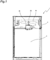
- FIG. 1 is a vertical cross-sectional view of an outdoor unit 1 using a fan motor waterproof structure of a first embodiment of the present disclosure.
- the outdoor unit 1 forms a part of a refrigerator or an air conditioner.
- the outdoor unit 1 of the first embodiment includes a rectangular parallelepiped casing 2, a heat exchanger 3 arranged in the casing 2, and a fan motor 20 arranged in the casing 2 and above the heat exchanger 3.
- the fan motor 20 is arranged such that a shaft 22 projects upward from a motor body 21. To the shaft 22 of the fan motor 20, a fan 10 is attached.
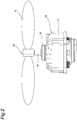
- FIG. 2 is a side view of the fan 10 and the fan motor 20 of the outdoor unit 1.
- a disk-shaped draining rubber 30 is fitted on an outside of a projecting portion of the shaft 22 of the fan motor 20 on the motor body 21 side.
- the draining rubber 30 is an example of a disk-shaped member, and is made of ethylene propylene diene rubber (EPDM) or the like.
- a tubular waterproof cap 40 is press-fitted to cover a boundary between an upper surface of the draining rubber 30 and the shaft 22.
- the waterproof cap 40 is an example of a tubular member, and is made of ethylene propylene diene rubber (EPDM) or the like.
- FIG. 3 is a cross-sectional view of the fan 10 and the fan motor 20.
- an annular stator 23 is arranged in the motor body 21 in the motor body 21 .
- a tubular rotor 24 arranged in the motor body 21 and on an outer peripheral side of the stator 23 is fixed.
- the shaft 22 is rotatably supported by bearings 25 and 26 arranged in the motor body 21.
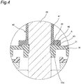
- FIG. 4 is an enlarged cross-sectional view of a main part of the fan motor 20 (a region S surrounded by a dotted line shown in FIG. 3 ).
- an inner peripheral side of the draining rubber 30 is fitted into an annular step part 22a provided on the shaft 22.
- an annular first protrusion 32 protruding upward is provided on the upper surface and the inner peripheral side of the draining rubber 30, an annular first protrusion 32 protruding upward is provided.
- the waterproof cap 40 has a cylindrical portion 41, a flange part 42 provided at a lower end of the cylindrical portion 41 so as to extend outward, and an annular second protrusion 43 provided so as to protrude downward on a lower surface and an outer peripheral side of the flange part 42.
- a lower end face of the annular second protrusion 43 of the waterproof cap 40 is in contact with the upper surface of a base part 31 of the draining rubber 30.
- FIG. 5 is a perspective view of the draining rubber 30 viewed from diagonally above.
- the draining rubber 30 has the disk-shaped base part 31 provided with a circular hole 30a into which the shaft 22 is inserted, the annular first protrusion 32 provided so as to protrude upward on the inner peripheral side of the base part 31, and a cylindrical portion 33 provided so as to extend downward on an outer peripheral side of the base part 31.
- FIG. 6 is a perspective view of the waterproof cap 40 viewed from diagonally above
- FIG. 7 is a perspective view of the waterproof cap 40 viewed from diagonally below.
- the cylindrical portion 41 of the waterproof cap 40 has a hole 41a through which the shaft 22 penetrates.
- the flange part 42 is provided at a lower end of the cylindrical portion 41 so as to extend outward.
- the annular second protrusion 43 is provided so as to protrude downward on the lower surface and the outer peripheral side of the flange part 42.
- a taper 41b is formed so as to gradually decrease from an inner peripheral side to an outer peripheral side.
- the fan motor waterproof structure having the above configuration, by press-fitting the waterproof cap 40 (the tubular member) on the draining rubber 30 (the disk-shaped member) and on the outer periphery of the shaft 22, to cause the waterproof cap 40 to cover the boundary between the upper surface of the draining rubber 30 and the shaft 22, it is possible to prevent dust and water from accumulating at an interface between an exposed portion of the shaft 22 and the draining rubber 30.
- This can improve the waterproofness of the fan motor 20. Therefore, it is possible to prevent corrosion of the shaft 22 and entering of water into the motor body 21 along the shaft 22, and to prevent damage of the bearing and the like by the entering water.
- the space A formed between the draining rubber 30 and the waterproof cap 40 makes it possible to prevent radially inward infiltration, due to the capillary phenomenon, of the water having entered between the draining rubber 30 and the waterproof cap 40 from outside.
- flange part 42 at the lower end of the waterproof cap 40 enables the boundary between the upper surface of the draining rubber 30 and the shaft 22 to be reliably covered with the flange part 42, and the waterproofness is further improved.
- the taper 41b at the upper end of the cylindrical portion 41 of the waterproof cap 40 so as to gradually decrease from the inner peripheral side to the outer peripheral side, dust and water fall along the taper 41b and is less likely to accumulate on the upper end of the waterproof cap 40, which can reduce risk of water entering between the waterproof cap 40 and the shaft 22 from the upper end side of the waterproof cap 40.
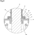
- FIG. 8 is an enlarged cross-sectional view of a main part of a fan motor 20 of an outdoor unit using a fan motor waterproof structure of a second embodiment of the present disclosure.
- the outdoor unit using the fan motor waterproof structure of the second embodiment has the same configuration as the outdoor unit 1 of the first embodiment except for the fan motor waterproof structure, and FIGS. 1 to 3 are incorporated.
- a lower end face of an annular second protrusion 44 of a waterproof cap 40 is not in contact with an upper surface of a base part 31 of a draining rubber 30, and there is a gap between the annular second protrusion 44 of the waterproof cap 40 and the base part 31 of the draining rubber 30.
- the fan motor waterproof structure in the second embodiment is different from the fan motor waterproof structure in the first embodiment in that a space A formed between the draining rubber 30 and the waterproof cap 40 is connected to an open space on a radially outer side.
- the fan motor waterproof structure of the second embodiment has an effect similar to that of the fan motor waterproof structure of the first embodiment.
- the space A formed between the draining rubber 30 and the waterproof cap 40 is connected to the open space on the radially outer side, it is possible to cause water having been blocked from entering in the space A between the draining rubber 30 and the waterproof cap 40 to be discharged outside along with rotation of the shaft 22, and to prevent accumulation of water between the draining rubber 30 and the waterproof cap 40.
- the flange part 42 is provided at the lower end of the cylindrical portion 41 of the waterproof cap 40, which is the tubular member, so as to extend outward.
- the flange part may be omitted, and a thickness of the tubular member in the radial direction may be increased, for example, to cover a boundary between the upper surface of the disk-shaped member and the shaft.
- the labyrinth seal is formed by providing the annular first protrusion 32 on the draining rubber 30, which is the disk-shaped member, and the annular second protrusion 43 or 44 on the flange part 42 of the waterproof cap 40, which is the tubular member.
- the labyrinth seal by providing the annular first protrusion protruding upward on the upper surface of the disk-shaped member and at a position facing the outer periphery of the flange part of the tubular member, and providing the annular second protrusion so as to protrude downward on the lower surface and the inner peripheral side of the flange part of the tubular member.
- the labyrinth seal may be formed by providing two or more of at least one of the annular first protrusion of the disk-shaped member or the annular second protrusion of the tubular member at intervals in the radial direction.
- the labyrinth seal by the annular first protrusion of the disk-shaped member and the annular second protrusion of the tubular member may be omitted. In this case as well, it is possible to prevent dust and water from accumulating at the interface between the exposed portion of the shaft and the disk-shaped member.
- individual end faces of the draining rubber 30 (the disk-shaped member) and the waterproof cap 40 (the tubular member) facing each other with the space A interposed in between may have a plurality of faces having different heights, and at least one of the plurality of faces of the draining rubber 30 may be located above at least one of the plurality of faces of the waterproof cap 40. This forms a maze between the draining rubber 30 and the waterproof cap 40, which can effectively prevent entering of water between the draining rubber 30 and the waterproof cap 40.
- ethylene propylene diene rubber (EPDM) or the like is used as a material for the draining rubber 30, which is the disk-shaped member, and the waterproof cap 40, which is the tubular member.
- EPDM ethylene propylene diene rubber
- the material of the disk-shaped member and the tubular member is not limited to this, and a material having water repellency and weather resistance is preferable.
- the draining rubber 30, which is the disk-shaped member is fitted and positioned on the annular step part 22a provided on the shaft 22, but the disk-shaped member may be positioned using an E-ring fitted to the shaft.
Landscapes
- Engineering & Computer Science (AREA)
- Power Engineering (AREA)
- Mechanical Engineering (AREA)
- General Engineering & Computer Science (AREA)
- Motor Or Generator Frames (AREA)
- Connection Of Motors, Electrical Generators, Mechanical Devices, And The Like (AREA)
Abstract
Description
- The present disclosure relates to a fan motor waterproof structure.
- Conventionally, as a fan motor waterproof structure, there is a mold electric motor in which a rotor shaft, a waterproof cap, and an E-ring are assembled (see, for example,
JP 6320555 B2 - In the above-described mold electric motor, the waterproof cap prevents water's entering a motor body from between the shaft and the motor body.
- Patent Literature 1:
JP 6320555 B2 - However, when the above-described mold electric motor is placed such that the shaft protrudes upward, there is a problem that the shaft is corroded due to accumulation of dust and water at an interface between an exposed portion of the shaft and the waterproof cap. In the above-described mold electric motor, when the shaft is corroded, waterproofness between the shaft and the waterproof cap is lost, and water enters the motor body along the shaft, which may cause damage of components inside the motor body, such as a shaft bearing, due to the entering water.
- The present disclosure proposes a fan motor waterproof structure that can improve waterproofness of a fan motor.
- A fan motor waterproof structure of the present disclosure includes:
- a fan motor arranged with a shaft projecting upward from a motor body;
- a disk-shaped member fitted to an outside of a projecting portion of the shaft of the fan motor on the motor body side; and
- a tubular member press-fitted onto the disk-shaped member and on an outer periphery of the shaft, tubular member covering a boundary between an upper surface of the disk-shaped member and the shaft.
- According to the present disclosure, by fitting the disk-shaped member on the outside of the projecting portion of the shaft of the fan motor on the motor body side, and press-fitting the tubular member onto the disk-shaped member and on the outer periphery of the shaft to cause the tubular member configured to cover the boundary between the upper surface of the disk-shaped member and the shaft, it is possible to prevent accumulation of dust and water at the interface between the exposed portion of the shaft and the disk-shaped member. This can improve the waterproofness of the fan motor.
- Further, in the fan motor waterproof structure according to one aspect of the present disclosure,
a space is formed between the disk-shaped member and the tubular member, and the space is connected to an open space on a radially outer side of the fan motor waterproof structure. - According to the present disclosure described above, the space formed between the disk-shaped member and the tubular member makes it possible to prevent radially inward infiltration, due to a capillary phenomenon, of water that has entered between the disk-shaped member and the tubular member from outside. Further, the space formed between the disk-shaped member and the tubular member is connected to the open space on the radially outer side, which causes water having been blocked from entering in the space between the disk-shaped member and the tubular member to be discharged outside along with rotation of the shaft, and to be prevented from accumulating between the disk-shaped member and the tubular member.
- Further, in the fan motor waterproof structure according to one aspect of the present disclosure,
- individual end faces of the disk-shaped member and the tubular member face each other with the space interposed in between, and have a plurality of faces having different heights, and
- at least one face of the plurality of faces of the disk-shaped member is located above at least one face of the plurality of faces of the tubular member.
- According to the present disclosure described above, individual end faces of the disk-shaped member and the tubular member facing each other with the space interposed in between have a plurality of faces having different axial heights of the shaft, which forms a maze between the disk-shaped member and the tubular member to make it possible to effectively prevent water from entering between the disk-shaped member and the tubular member.
- Further, in the fan motor waterproof structure according to one aspect of the present disclosure,
a flange part is provided at a lower end of the tubular member. - According to the present disclosure, providing the flange part at the lower end of the tubular member enables the boundary between the upper surface of the disk-shaped member and the shaft to be reliably covered with the flange part, and the waterproofness is further improved.
- Further, in the fan motor waterproof structure according to one aspect of the present disclosure,
- a flange part is provided at a lower end of the tubular member,
- an annular first protrusion protruding upward is provided on an upper surface and an inner peripheral side of the disk-shaped member,
- an annular second protrusion protruding downward is provided on a lower surface and an outer peripheral side of the flange part of the tubular member, and
- a labyrinth seal is formed by the annular first protrusion of the disk-shaped member and the annular second protrusion of the tubular member.
- According to the present disclosure, it is possible to effectively prevent water from entering between the disk-shaped member and the tubular member, by the labyrinth seal formed by the annular first protrusion protruding upward on the upper surface and the inner peripheral side of the disk-shaped member and the annular second protrusion protruding downward on the lower surface and the outer peripheral side of the flange part of the tubular member.
- Further, in the fan motor waterproof structure according to one aspect of the present disclosure,
a taper is formed on an upper end of the tubular member to gradually decrease from an inner peripheral side to an outer peripheral side. - According to the present disclosure, by forming the taper on the upper end of the tubular member to gradually decrease from the inner peripheral side to the outer peripheral side, it is possible to prevent accumulation of dust and water at the upper end of the tubular member, and to reduce risk of water entering between the tubular member and the shaft from the upper end side of the tubular member.
-
-
FIG. 1 is a vertical cross-sectional view of an outdoor unit using a fan motor waterproof structure of a first embodiment of the present disclosure. -
FIG. 2 is a side view of a fan and a fan motor of the outdoor unit. -
FIG. 3 is a cross-sectional view of the fan and the fan motor. -
FIG. 4 is an enlarged cross-sectional view of a main part of the fan motor. -
FIG. 5 is a perspective view of a draining rubber viewed from diagonally above. -
FIG. 6 is a perspective view of a waterproof cap viewed from diagonally above. -
FIG. 7 is a perspective view of the waterproof cap viewed from diagonally below. -
FIG. 8 is an enlarged cross-sectional view of a main part of a fan motor of an outdoor unit using a fan motor waterproof structure of a second embodiment of the present disclosure. - Hereinafter, embodiments will be described. Note that, in the drawings, identical reference signs represent identical or corresponding parts. In addition, the dimensions on the drawings such as a length, a width, a thickness, and a depth are appropriately changed from the actual scale for the purpose of clarifying and simplifying the drawings, and do not represent the actual relative dimensions.
-
FIG. 1 is a vertical cross-sectional view of an outdoor unit 1 using a fan motor waterproof structure of a first embodiment of the present disclosure. The outdoor unit 1 forms a part of a refrigerator or an air conditioner. - As shown in
FIG. 1 , the outdoor unit 1 of the first embodiment includes a rectangularparallelepiped casing 2, aheat exchanger 3 arranged in thecasing 2, and afan motor 20 arranged in thecasing 2 and above theheat exchanger 3. Thefan motor 20 is arranged such that ashaft 22 projects upward from amotor body 21. To theshaft 22 of thefan motor 20, afan 10 is attached. -
FIG. 2 is a side view of thefan 10 and thefan motor 20 of the outdoor unit 1. As shown inFIG. 2 , on an outside of a projecting portion of theshaft 22 of thefan motor 20 on themotor body 21 side, a disk-shaped drainingrubber 30 is fitted. The drainingrubber 30 is an example of a disk-shaped member, and is made of ethylene propylene diene rubber (EPDM) or the like. - Further, on the
draining rubber 30 and on an outer periphery of theshaft 22, a tubularwaterproof cap 40 is press-fitted to cover a boundary between an upper surface of the drainingrubber 30 and theshaft 22. Thewaterproof cap 40 is an example of a tubular member, and is made of ethylene propylene diene rubber (EPDM) or the like. - Further,
FIG. 3 is a cross-sectional view of thefan 10 and thefan motor 20. As shown inFIG. 3 , in themotor body 21, anannular stator 23 is arranged. To theshaft 22, atubular rotor 24 arranged in themotor body 21 and on an outer peripheral side of thestator 23 is fixed. Theshaft 22 is rotatably supported bybearings motor body 21. -
FIG. 4 is an enlarged cross-sectional view of a main part of the fan motor 20 (a region S surrounded by a dotted line shown inFIG. 3 ). As shown inFIG. 4 , an inner peripheral side of the drainingrubber 30 is fitted into anannular step part 22a provided on theshaft 22. On the upper surface and the inner peripheral side of the drainingrubber 30, an annularfirst protrusion 32 protruding upward is provided. - Further, the
waterproof cap 40 has acylindrical portion 41, aflange part 42 provided at a lower end of thecylindrical portion 41 so as to extend outward, and an annularsecond protrusion 43 provided so as to protrude downward on a lower surface and an outer peripheral side of theflange part 42. - By the annular
first protrusion 32 of the drainingrubber 30 and the annularsecond protrusion 43 of thewaterproof cap 40, a labyrinth seal is formed. Further, a space A is formed between the drainingrubber 30 and thewaterproof cap 40. - A lower end face of the annular
second protrusion 43 of thewaterproof cap 40 is in contact with the upper surface of abase part 31 of the drainingrubber 30. -
FIG. 5 is a perspective view of the drainingrubber 30 viewed from diagonally above. As shown inFIG. 5 , the drainingrubber 30 has the disk-shapedbase part 31 provided with acircular hole 30a into which theshaft 22 is inserted, the annularfirst protrusion 32 provided so as to protrude upward on the inner peripheral side of thebase part 31, and acylindrical portion 33 provided so as to extend downward on an outer peripheral side of thebase part 31. -
FIG. 6 is a perspective view of thewaterproof cap 40 viewed from diagonally above, andFIG. 7 is a perspective view of thewaterproof cap 40 viewed from diagonally below. As shown inFIGS. 6 and7 , thecylindrical portion 41 of thewaterproof cap 40 has ahole 41a through which theshaft 22 penetrates. Further, theflange part 42 is provided at a lower end of thecylindrical portion 41 so as to extend outward. Further, the annularsecond protrusion 43 is provided so as to protrude downward on the lower surface and the outer peripheral side of theflange part 42. - At an upper end of the
cylindrical portion 41 of thewaterproof cap 40, ataper 41b is formed so as to gradually decrease from an inner peripheral side to an outer peripheral side. - According to the fan motor waterproof structure having the above configuration, by press-fitting the waterproof cap 40 (the tubular member) on the draining rubber 30 (the disk-shaped member) and on the outer periphery of the
shaft 22, to cause thewaterproof cap 40 to cover the boundary between the upper surface of the drainingrubber 30 and theshaft 22, it is possible to prevent dust and water from accumulating at an interface between an exposed portion of theshaft 22 and the drainingrubber 30. This can improve the waterproofness of thefan motor 20. Therefore, it is possible to prevent corrosion of theshaft 22 and entering of water into themotor body 21 along theshaft 22, and to prevent damage of the bearing and the like by the entering water. - Further, the space A formed between the draining
rubber 30 and thewaterproof cap 40 makes it possible to prevent radially inward infiltration, due to the capillary phenomenon, of the water having entered between the drainingrubber 30 and thewaterproof cap 40 from outside. - In addition, providing the
flange part 42 at the lower end of thewaterproof cap 40 enables the boundary between the upper surface of the drainingrubber 30 and theshaft 22 to be reliably covered with theflange part 42, and the waterproofness is further improved. - In addition, it is possible to effectively prevent water from entering between the draining
rubber 30 and thewaterproof cap 40, by the labyrinth seal formed by the annularfirst protrusion 32 protruding upward on the upper surface and the inner peripheral side of the drainingrubber 30 and the annularsecond protrusion 43 protruding downward on the lower surface and the outer peripheral side of theflange part 42 of thewaterproof cap 40. - Further, by forming the
taper 41b at the upper end of thecylindrical portion 41 of thewaterproof cap 40 so as to gradually decrease from the inner peripheral side to the outer peripheral side, dust and water fall along thetaper 41b and is less likely to accumulate on the upper end of thewaterproof cap 40, which can reduce risk of water entering between thewaterproof cap 40 and theshaft 22 from the upper end side of thewaterproof cap 40. -
FIG. 8 is an enlarged cross-sectional view of a main part of afan motor 20 of an outdoor unit using a fan motor waterproof structure of a second embodiment of the present disclosure. The outdoor unit using the fan motor waterproof structure of the second embodiment has the same configuration as the outdoor unit 1 of the first embodiment except for the fan motor waterproof structure, andFIGS. 1 to 3 are incorporated. - In the second embodiment, a lower end face of an annular
second protrusion 44 of awaterproof cap 40 is not in contact with an upper surface of abase part 31 of a drainingrubber 30, and there is a gap between the annularsecond protrusion 44 of thewaterproof cap 40 and thebase part 31 of the drainingrubber 30. - As shown in
FIG. 8 , the fan motor waterproof structure in the second embodiment is different from the fan motor waterproof structure in the first embodiment in that a space A formed between the drainingrubber 30 and thewaterproof cap 40 is connected to an open space on a radially outer side. - The fan motor waterproof structure of the second embodiment has an effect similar to that of the fan motor waterproof structure of the first embodiment.
- In addition, since the space A formed between the draining
rubber 30 and thewaterproof cap 40 is connected to the open space on the radially outer side, it is possible to cause water having been blocked from entering in the space A between the drainingrubber 30 and thewaterproof cap 40 to be discharged outside along with rotation of theshaft 22, and to prevent accumulation of water between the drainingrubber 30 and thewaterproof cap 40. - In the first and second embodiments, the
flange part 42 is provided at the lower end of thecylindrical portion 41 of thewaterproof cap 40, which is the tubular member, so as to extend outward. However, the flange part may be omitted, and a thickness of the tubular member in the radial direction may be increased, for example, to cover a boundary between the upper surface of the disk-shaped member and the shaft. - Further, in the first and second embodiments described above, the labyrinth seal is formed by providing the annular
first protrusion 32 on the drainingrubber 30, which is the disk-shaped member, and the annularsecond protrusion flange part 42 of thewaterproof cap 40, which is the tubular member. However, it is also possible to form the labyrinth seal by providing the annular first protrusion protruding upward on the upper surface of the disk-shaped member and at a position facing the outer periphery of the flange part of the tubular member, and providing the annular second protrusion so as to protrude downward on the lower surface and the inner peripheral side of the flange part of the tubular member. - Moreover, the labyrinth seal may be formed by providing two or more of at least one of the annular first protrusion of the disk-shaped member or the annular second protrusion of the tubular member at intervals in the radial direction.
- Further, the labyrinth seal by the annular first protrusion of the disk-shaped member and the annular second protrusion of the tubular member may be omitted. In this case as well, it is possible to prevent dust and water from accumulating at the interface between the exposed portion of the shaft and the disk-shaped member.
- Further, individual end faces of the draining rubber 30 (the disk-shaped member) and the waterproof cap 40 (the tubular member) facing each other with the space A interposed in between may have a plurality of faces having different heights, and at least one of the plurality of faces of the draining
rubber 30 may be located above at least one of the plurality of faces of thewaterproof cap 40. This forms a maze between the drainingrubber 30 and thewaterproof cap 40, which can effectively prevent entering of water between the drainingrubber 30 and thewaterproof cap 40. - Further, in the first and second embodiments described above, ethylene propylene diene rubber (EPDM) or the like is used as a material for the draining
rubber 30, which is the disk-shaped member, and thewaterproof cap 40, which is the tubular member. However, the material of the disk-shaped member and the tubular member is not limited to this, and a material having water repellency and weather resistance is preferable. - Further, in the first and second embodiments, the draining
rubber 30, which is the disk-shaped member, is fitted and positioned on theannular step part 22a provided on theshaft 22, but the disk-shaped member may be positioned using an E-ring fitted to the shaft. - The foregoing description concerns specific embodiments of the present disclosure; however, the present disclosure is not limited to the first and second embodiments, and various modifications and variations may be made within the scope of the present disclosure.
-
- 1
- Outdoor unit
- 2
- Casing
- 3
- Heat exchanger
- 10
- Fan
- 20
- Fan motor
- 21
- Motor body
- 22
- Shaft
- 23
- Stator
- 24
- Rotor
- 25, 26
- Bearing
- 30
- Draining rubber
- 30a
- Circular hole
- 31
- Disk-shaped base part
- 32
- Annular first protrusion
- 33
- Cylindrical portion
- 40
- Waterproof cap
- 41
- Cylindrical portion
- 41a
- Hole
- 41b
- Taper
- 42
- Flange part
- 43, 44
- Annular second protrusion
Claims (6)
- A fan motor waterproof structure comprising:a fan motor (20) arranged with a shaft (22) projecting upward from a motor body (21);a disk-shaped member (30) fitted to an outside of a projecting portion of the shaft (22) of the fan motor (20) on the motor body (21) side; anda tubular member (40) press-fitted onto the disk-shaped member (30) and on an outer periphery of the shaft (22), the tubular member (40) covering a boundary between an upper surface of the disk-shaped member (30) and the shaft (22).
- The fan motor waterproof structure according to claim 1, wherein
a space (A) is formed between the disk-shaped member (30) and the tubular member (40), and the space (A) is connected to an open space on a radially outer side. - The fan motor waterproof structure according to claim 2, whereinindividual end faces of the disk-shaped member (30) and the tubular member (40) face each other with the space (A) interposed in between, and have a plurality of faces having different heights, andat least one face of the plurality of faces of the disk-shaped member (30) is located above at least one face of the plurality of faces of the tubular member (40).
- The fan motor waterproof structure according to any one of claims 1 to 3, wherein
at a lower end of the tubular member (40), a flange part (42) is provided. - The fan motor waterproof structure according to claim 1 or 2, whereinat a lower end of the tubular member (40), a flange part (42) is provided,there is provided an annular first protrusion (32) protruding upward on an upper surface and an inner peripheral side of the disk-shaped member (30),there is provided an annular second protrusion (43, 44) protruding downward on a lower surface and an outer peripheral side of the flange part (42) of the tubular member (40), anda labyrinth seal is formed by the annular first protrusion (32) of the disk-shaped member (30) and the annular second protrusion (43, 44) of the tubular member (40).
- The fan motor waterproof structure according to any one of claims 1 to 5, wherein
a taper (41b) is formed at an upper end of the tubular member (40) to gradually decrease from an inner peripheral side toward an outer peripheral side.
Applications Claiming Priority (2)
| Application Number | Priority Date | Filing Date | Title |
|---|---|---|---|
| JP2018230915A JP6848957B2 (en) | 2018-12-10 | 2018-12-10 | Fan motor waterproof structure |
| PCT/JP2019/043608 WO2020121698A1 (en) | 2018-12-10 | 2019-11-07 | Fan motor waterproof structure |
Publications (3)
| Publication Number | Publication Date |
|---|---|
| EP3876398A1 true EP3876398A1 (en) | 2021-09-08 |
| EP3876398A4 EP3876398A4 (en) | 2021-12-29 |
| EP3876398B1 EP3876398B1 (en) | 2023-06-21 |
Family
ID=71076322
Family Applications (1)
| Application Number | Title | Priority Date | Filing Date |
|---|---|---|---|
| EP19896498.3A Active EP3876398B1 (en) | 2018-12-10 | 2019-11-07 | Fan motor waterproof structure |
Country Status (6)
| Country | Link |
|---|---|
| US (1) | US11764634B2 (en) |
| EP (1) | EP3876398B1 (en) |
| JP (1) | JP6848957B2 (en) |
| CN (1) | CN112840533B (en) |
| ES (1) | ES2949567T3 (en) |
| WO (1) | WO2020121698A1 (en) |
Families Citing this family (1)
| Publication number | Priority date | Publication date | Assignee | Title |
|---|---|---|---|---|
| US20250233474A1 (en) * | 2022-04-14 | 2025-07-17 | Minebea Mitsumi Inc. | Motor |
Family Cites Families (7)
| Publication number | Priority date | Publication date | Assignee | Title |
|---|---|---|---|---|
| JPS54180210U (en) * | 1978-06-09 | 1979-12-20 | ||
| JPH038060Y2 (en) | 1985-07-19 | 1991-02-27 | ||
| CN2229566Y (en) * | 1995-04-13 | 1996-06-19 | 长春市北方变压器组件研究所 | Labyrinth seal protector for fan shaft extension of transformer |
| JP5000851B2 (en) | 2005-02-16 | 2012-08-15 | プライムアースEvエナジー株式会社 | Fan structure and battery pack |
| JP6046466B2 (en) * | 2012-11-26 | 2016-12-14 | 住友重機械工業株式会社 | Motor waterproof structure |
| CN103742430B (en) * | 2013-12-19 | 2015-05-27 | 浙江双双制冷设备有限公司 | Motor assembly for centrifugal fan |
| WO2016063428A1 (en) | 2014-10-24 | 2016-04-28 | 三菱電機株式会社 | Electric-motor stator, electric motor, and air conditioner |
-
2018
- 2018-12-10 JP JP2018230915A patent/JP6848957B2/en active Active
-
2019
- 2019-11-07 US US17/311,919 patent/US11764634B2/en active Active
- 2019-11-07 ES ES19896498T patent/ES2949567T3/en active Active
- 2019-11-07 EP EP19896498.3A patent/EP3876398B1/en active Active
- 2019-11-07 WO PCT/JP2019/043608 patent/WO2020121698A1/en not_active Ceased
- 2019-11-07 CN CN201980067138.4A patent/CN112840533B/en active Active
Also Published As
| Publication number | Publication date |
|---|---|
| US11764634B2 (en) | 2023-09-19 |
| EP3876398B1 (en) | 2023-06-21 |
| CN112840533A (en) | 2021-05-25 |
| US20220029499A1 (en) | 2022-01-27 |
| WO2020121698A1 (en) | 2020-06-18 |
| JP6848957B2 (en) | 2021-03-24 |
| CN112840533B (en) | 2024-06-18 |
| JP2020096406A (en) | 2020-06-18 |
| ES2949567T3 (en) | 2023-09-29 |
| EP3876398A4 (en) | 2021-12-29 |
Similar Documents
| Publication | Publication Date | Title |
|---|---|---|
| CN109958629B (en) | Air blower | |
| US9033680B2 (en) | Electric fan | |
| US8678785B2 (en) | Ventilation fan | |
| EP3672031B1 (en) | Motor sealing structure and motor | |
| KR101493635B1 (en) | Fan motor | |
| JP6354309B2 (en) | Blower device | |
| JP5212069B2 (en) | Molded electric motor and air conditioner outdoor unit equipped with the same | |
| EP3876398B1 (en) | Fan motor waterproof structure | |
| CN112956117A (en) | Bearing cap and motor using same | |
| EP1412641B1 (en) | Ventilation unit | |
| JP2008278690A (en) | Electric motor | |
| US11025123B2 (en) | Motor and fan motor | |
| JP2014107909A (en) | Waterproof structure of motor | |
| US2743385A (en) | Vertical dynamoelectric machine | |
| JP2015142437A (en) | Electric motor | |
| JP2009024649A (en) | Centrifugal fan with drip-proof structure | |
| US20220320982A1 (en) | Motor and electrical product | |
| US20190186495A1 (en) | Blower | |
| US20220320983A1 (en) | Motor and electrical product | |
| JP3795991B2 (en) | Waterproof structure of fan drive motor | |
| JP6069029B2 (en) | Rotating electric machine | |
| WO2024252803A1 (en) | Rotating electrical machine | |
| CN211314649U (en) | Centrifugal fan and blower | |
| CN116964343A (en) | Bearing protector | |
| JP2010270843A (en) | Motor and generator |
Legal Events
| Date | Code | Title | Description |
|---|---|---|---|
| STAA | Information on the status of an ep patent application or granted ep patent |
Free format text: STATUS: THE INTERNATIONAL PUBLICATION HAS BEEN MADE |
|
| PUAI | Public reference made under article 153(3) epc to a published international application that has entered the european phase |
Free format text: ORIGINAL CODE: 0009012 |
|
| STAA | Information on the status of an ep patent application or granted ep patent |
Free format text: STATUS: REQUEST FOR EXAMINATION WAS MADE |
|
| 17P | Request for examination filed |
Effective date: 20210531 |
|
| AK | Designated contracting states |
Kind code of ref document: A1 Designated state(s): AL AT BE BG CH CY CZ DE DK EE ES FI FR GB GR HR HU IE IS IT LI LT LU LV MC MK MT NL NO PL PT RO RS SE SI SK SM TR |
|
| A4 | Supplementary search report drawn up and despatched |
Effective date: 20211126 |
|
| RIC1 | Information provided on ipc code assigned before grant |
Ipc: F04D 29/64 20060101ALI20211122BHEP Ipc: F04D 29/10 20060101ALI20211122BHEP Ipc: H02K 7/14 20060101ALI20211122BHEP Ipc: H02K 5/10 20060101AFI20211122BHEP |
|
| DAV | Request for validation of the european patent (deleted) | ||
| DAX | Request for extension of the european patent (deleted) | ||
| STAA | Information on the status of an ep patent application or granted ep patent |
Free format text: STATUS: EXAMINATION IS IN PROGRESS |
|
| 17Q | First examination report despatched |
Effective date: 20220811 |
|
| RAP3 | Party data changed (applicant data changed or rights of an application transferred) |
Owner name: DAIKIN INDUSTRIES, LTD. |
|
| GRAP | Despatch of communication of intention to grant a patent |
Free format text: ORIGINAL CODE: EPIDOSNIGR1 |
|
| STAA | Information on the status of an ep patent application or granted ep patent |
Free format text: STATUS: GRANT OF PATENT IS INTENDED |
|
| INTG | Intention to grant announced |
Effective date: 20230223 |
|
| GRAS | Grant fee paid |
Free format text: ORIGINAL CODE: EPIDOSNIGR3 |
|
| GRAA | (expected) grant |
Free format text: ORIGINAL CODE: 0009210 |
|
| STAA | Information on the status of an ep patent application or granted ep patent |
Free format text: STATUS: THE PATENT HAS BEEN GRANTED |
|
| AK | Designated contracting states |
Kind code of ref document: B1 Designated state(s): AL AT BE BG CH CY CZ DE DK EE ES FI FR GB GR HR HU IE IS IT LI LT LU LV MC MK MT NL NO PL PT RO RS SE SI SK SM TR |
|
| REG | Reference to a national code |
Ref country code: CH Ref legal event code: EP |
|
| P01 | Opt-out of the competence of the unified patent court (upc) registered |
Effective date: 20230525 |
|
| REG | Reference to a national code |
Ref country code: DE Ref legal event code: R096 Ref document number: 602019031513 Country of ref document: DE |
|
| REG | Reference to a national code |
Ref country code: AT Ref legal event code: REF Ref document number: 1581621 Country of ref document: AT Kind code of ref document: T Effective date: 20230715 |
|
| REG | Reference to a national code |
Ref country code: IE Ref legal event code: FG4D |
|
| REG | Reference to a national code |
Ref country code: ES Ref legal event code: FG2A Ref document number: 2949567 Country of ref document: ES Kind code of ref document: T3 Effective date: 20230929 |
|
| REG | Reference to a national code |
Ref country code: LT Ref legal event code: MG9D |
|
| REG | Reference to a national code |
Ref country code: NL Ref legal event code: MP Effective date: 20230621 |
|
| PG25 | Lapsed in a contracting state [announced via postgrant information from national office to epo] |
Ref country code: SE Free format text: LAPSE BECAUSE OF FAILURE TO SUBMIT A TRANSLATION OF THE DESCRIPTION OR TO PAY THE FEE WITHIN THE PRESCRIBED TIME-LIMIT Effective date: 20230621 Ref country code: NO Free format text: LAPSE BECAUSE OF FAILURE TO SUBMIT A TRANSLATION OF THE DESCRIPTION OR TO PAY THE FEE WITHIN THE PRESCRIBED TIME-LIMIT Effective date: 20230921 |
|
| REG | Reference to a national code |
Ref country code: AT Ref legal event code: MK05 Ref document number: 1581621 Country of ref document: AT Kind code of ref document: T Effective date: 20230621 |
|
| PG25 | Lapsed in a contracting state [announced via postgrant information from national office to epo] |
Ref country code: RS Free format text: LAPSE BECAUSE OF FAILURE TO SUBMIT A TRANSLATION OF THE DESCRIPTION OR TO PAY THE FEE WITHIN THE PRESCRIBED TIME-LIMIT Effective date: 20230621 Ref country code: NL Free format text: LAPSE BECAUSE OF FAILURE TO SUBMIT A TRANSLATION OF THE DESCRIPTION OR TO PAY THE FEE WITHIN THE PRESCRIBED TIME-LIMIT Effective date: 20230621 Ref country code: LV Free format text: LAPSE BECAUSE OF FAILURE TO SUBMIT A TRANSLATION OF THE DESCRIPTION OR TO PAY THE FEE WITHIN THE PRESCRIBED TIME-LIMIT Effective date: 20230621 Ref country code: LT Free format text: LAPSE BECAUSE OF FAILURE TO SUBMIT A TRANSLATION OF THE DESCRIPTION OR TO PAY THE FEE WITHIN THE PRESCRIBED TIME-LIMIT Effective date: 20230621 Ref country code: HR Free format text: LAPSE BECAUSE OF FAILURE TO SUBMIT A TRANSLATION OF THE DESCRIPTION OR TO PAY THE FEE WITHIN THE PRESCRIBED TIME-LIMIT Effective date: 20230621 Ref country code: GR Free format text: LAPSE BECAUSE OF FAILURE TO SUBMIT A TRANSLATION OF THE DESCRIPTION OR TO PAY THE FEE WITHIN THE PRESCRIBED TIME-LIMIT Effective date: 20230922 |
|
| PG25 | Lapsed in a contracting state [announced via postgrant information from national office to epo] |
Ref country code: FI Free format text: LAPSE BECAUSE OF FAILURE TO SUBMIT A TRANSLATION OF THE DESCRIPTION OR TO PAY THE FEE WITHIN THE PRESCRIBED TIME-LIMIT Effective date: 20230621 |
|
| PG25 | Lapsed in a contracting state [announced via postgrant information from national office to epo] |
Ref country code: SK Free format text: LAPSE BECAUSE OF FAILURE TO SUBMIT A TRANSLATION OF THE DESCRIPTION OR TO PAY THE FEE WITHIN THE PRESCRIBED TIME-LIMIT Effective date: 20230621 |
|
| PG25 | Lapsed in a contracting state [announced via postgrant information from national office to epo] |
Ref country code: IS Free format text: LAPSE BECAUSE OF FAILURE TO SUBMIT A TRANSLATION OF THE DESCRIPTION OR TO PAY THE FEE WITHIN THE PRESCRIBED TIME-LIMIT Effective date: 20231021 |
|
| PG25 | Lapsed in a contracting state [announced via postgrant information from national office to epo] |
Ref country code: SM Free format text: LAPSE BECAUSE OF FAILURE TO SUBMIT A TRANSLATION OF THE DESCRIPTION OR TO PAY THE FEE WITHIN THE PRESCRIBED TIME-LIMIT Effective date: 20230621 Ref country code: SK Free format text: LAPSE BECAUSE OF FAILURE TO SUBMIT A TRANSLATION OF THE DESCRIPTION OR TO PAY THE FEE WITHIN THE PRESCRIBED TIME-LIMIT Effective date: 20230621 Ref country code: RO Free format text: LAPSE BECAUSE OF FAILURE TO SUBMIT A TRANSLATION OF THE DESCRIPTION OR TO PAY THE FEE WITHIN THE PRESCRIBED TIME-LIMIT Effective date: 20230621 Ref country code: PT Free format text: LAPSE BECAUSE OF FAILURE TO SUBMIT A TRANSLATION OF THE DESCRIPTION OR TO PAY THE FEE WITHIN THE PRESCRIBED TIME-LIMIT Effective date: 20231023 Ref country code: IS Free format text: LAPSE BECAUSE OF FAILURE TO SUBMIT A TRANSLATION OF THE DESCRIPTION OR TO PAY THE FEE WITHIN THE PRESCRIBED TIME-LIMIT Effective date: 20231021 Ref country code: EE Free format text: LAPSE BECAUSE OF FAILURE TO SUBMIT A TRANSLATION OF THE DESCRIPTION OR TO PAY THE FEE WITHIN THE PRESCRIBED TIME-LIMIT Effective date: 20230621 Ref country code: CZ Free format text: LAPSE BECAUSE OF FAILURE TO SUBMIT A TRANSLATION OF THE DESCRIPTION OR TO PAY THE FEE WITHIN THE PRESCRIBED TIME-LIMIT Effective date: 20230621 Ref country code: AT Free format text: LAPSE BECAUSE OF FAILURE TO SUBMIT A TRANSLATION OF THE DESCRIPTION OR TO PAY THE FEE WITHIN THE PRESCRIBED TIME-LIMIT Effective date: 20230621 |
|
| PG25 | Lapsed in a contracting state [announced via postgrant information from national office to epo] |
Ref country code: PL Free format text: LAPSE BECAUSE OF FAILURE TO SUBMIT A TRANSLATION OF THE DESCRIPTION OR TO PAY THE FEE WITHIN THE PRESCRIBED TIME-LIMIT Effective date: 20230621 |
|
| REG | Reference to a national code |
Ref country code: DE Ref legal event code: R097 Ref document number: 602019031513 Country of ref document: DE |
|
| PLBE | No opposition filed within time limit |
Free format text: ORIGINAL CODE: 0009261 |
|
| STAA | Information on the status of an ep patent application or granted ep patent |
Free format text: STATUS: NO OPPOSITION FILED WITHIN TIME LIMIT |
|
| PG25 | Lapsed in a contracting state [announced via postgrant information from national office to epo] |
Ref country code: DK Free format text: LAPSE BECAUSE OF FAILURE TO SUBMIT A TRANSLATION OF THE DESCRIPTION OR TO PAY THE FEE WITHIN THE PRESCRIBED TIME-LIMIT Effective date: 20230621 |
|
| PG25 | Lapsed in a contracting state [announced via postgrant information from national office to epo] |
Ref country code: SI Free format text: LAPSE BECAUSE OF FAILURE TO SUBMIT A TRANSLATION OF THE DESCRIPTION OR TO PAY THE FEE WITHIN THE PRESCRIBED TIME-LIMIT Effective date: 20230621 |
|
| 26N | No opposition filed |
Effective date: 20240322 |
|
| PG25 | Lapsed in a contracting state [announced via postgrant information from national office to epo] |
Ref country code: SI Free format text: LAPSE BECAUSE OF FAILURE TO SUBMIT A TRANSLATION OF THE DESCRIPTION OR TO PAY THE FEE WITHIN THE PRESCRIBED TIME-LIMIT Effective date: 20230621 |
|
| REG | Reference to a national code |
Ref country code: CH Ref legal event code: PL |
|
| PG25 | Lapsed in a contracting state [announced via postgrant information from national office to epo] |
Ref country code: MC Free format text: LAPSE BECAUSE OF FAILURE TO SUBMIT A TRANSLATION OF THE DESCRIPTION OR TO PAY THE FEE WITHIN THE PRESCRIBED TIME-LIMIT Effective date: 20230621 |
|
| PG25 | Lapsed in a contracting state [announced via postgrant information from national office to epo] |
Ref country code: LU Free format text: LAPSE BECAUSE OF NON-PAYMENT OF DUE FEES Effective date: 20231107 |
|
| PG25 | Lapsed in a contracting state [announced via postgrant information from national office to epo] |
Ref country code: CH Free format text: LAPSE BECAUSE OF NON-PAYMENT OF DUE FEES Effective date: 20231130 |
|
| PG25 | Lapsed in a contracting state [announced via postgrant information from national office to epo] |
Ref country code: MC Free format text: LAPSE BECAUSE OF FAILURE TO SUBMIT A TRANSLATION OF THE DESCRIPTION OR TO PAY THE FEE WITHIN THE PRESCRIBED TIME-LIMIT Effective date: 20230621 Ref country code: LU Free format text: LAPSE BECAUSE OF NON-PAYMENT OF DUE FEES Effective date: 20231107 Ref country code: CH Free format text: LAPSE BECAUSE OF NON-PAYMENT OF DUE FEES Effective date: 20231130 |
|
| REG | Reference to a national code |
Ref country code: BE Ref legal event code: MM Effective date: 20231130 |
|
| REG | Reference to a national code |
Ref country code: IE Ref legal event code: MM4A |
|
| PG25 | Lapsed in a contracting state [announced via postgrant information from national office to epo] |
Ref country code: IE Free format text: LAPSE BECAUSE OF NON-PAYMENT OF DUE FEES Effective date: 20231107 |
|
| PG25 | Lapsed in a contracting state [announced via postgrant information from national office to epo] |
Ref country code: BE Free format text: LAPSE BECAUSE OF NON-PAYMENT OF DUE FEES Effective date: 20231130 |
|
| PG25 | Lapsed in a contracting state [announced via postgrant information from national office to epo] |
Ref country code: IE Free format text: LAPSE BECAUSE OF NON-PAYMENT OF DUE FEES Effective date: 20231107 Ref country code: BE Free format text: LAPSE BECAUSE OF NON-PAYMENT OF DUE FEES Effective date: 20231130 |
|
| PG25 | Lapsed in a contracting state [announced via postgrant information from national office to epo] |
Ref country code: BG Free format text: LAPSE BECAUSE OF FAILURE TO SUBMIT A TRANSLATION OF THE DESCRIPTION OR TO PAY THE FEE WITHIN THE PRESCRIBED TIME-LIMIT Effective date: 20230621 |
|
| PG25 | Lapsed in a contracting state [announced via postgrant information from national office to epo] |
Ref country code: BG Free format text: LAPSE BECAUSE OF FAILURE TO SUBMIT A TRANSLATION OF THE DESCRIPTION OR TO PAY THE FEE WITHIN THE PRESCRIBED TIME-LIMIT Effective date: 20230621 |
|
| PG25 | Lapsed in a contracting state [announced via postgrant information from national office to epo] |
Ref country code: CY Free format text: LAPSE BECAUSE OF FAILURE TO SUBMIT A TRANSLATION OF THE DESCRIPTION OR TO PAY THE FEE WITHIN THE PRESCRIBED TIME-LIMIT; INVALID AB INITIO Effective date: 20191107 |
|
| PG25 | Lapsed in a contracting state [announced via postgrant information from national office to epo] |
Ref country code: HU Free format text: LAPSE BECAUSE OF FAILURE TO SUBMIT A TRANSLATION OF THE DESCRIPTION OR TO PAY THE FEE WITHIN THE PRESCRIBED TIME-LIMIT; INVALID AB INITIO Effective date: 20191107 |
|
| PG25 | Lapsed in a contracting state [announced via postgrant information from national office to epo] |
Ref country code: TR Free format text: LAPSE BECAUSE OF FAILURE TO SUBMIT A TRANSLATION OF THE DESCRIPTION OR TO PAY THE FEE WITHIN THE PRESCRIBED TIME-LIMIT Effective date: 20230621 |
|
| PGFP | Annual fee paid to national office [announced via postgrant information from national office to epo] |
Ref country code: DE Payment date: 20251119 Year of fee payment: 7 |
|
| PGFP | Annual fee paid to national office [announced via postgrant information from national office to epo] |
Ref country code: GB Payment date: 20251121 Year of fee payment: 7 |
|
| PGFP | Annual fee paid to national office [announced via postgrant information from national office to epo] |
Ref country code: IT Payment date: 20251125 Year of fee payment: 7 |
|
| PGFP | Annual fee paid to national office [announced via postgrant information from national office to epo] |
Ref country code: FR Payment date: 20251126 Year of fee payment: 7 |
|
| PGFP | Annual fee paid to national office [announced via postgrant information from national office to epo] |
Ref country code: ES Payment date: 20251229 Year of fee payment: 7 |