EP3876354A1 - Terminal block - Google Patents
Terminal block Download PDFInfo
- Publication number
- EP3876354A1 EP3876354A1 EP19897112.9A EP19897112A EP3876354A1 EP 3876354 A1 EP3876354 A1 EP 3876354A1 EP 19897112 A EP19897112 A EP 19897112A EP 3876354 A1 EP3876354 A1 EP 3876354A1
- Authority
- EP
- European Patent Office
- Prior art keywords
- terminal block
- pair
- wall portion
- terminal
- coupling
- Prior art date
- Legal status (The legal status is an assumption and is not a legal conclusion. Google has not performed a legal analysis and makes no representation as to the accuracy of the status listed.)
- Pending
Links
Images




Classifications
-
- H—ELECTRICITY
- H01—ELECTRIC ELEMENTS
- H01R—ELECTRICALLY-CONDUCTIVE CONNECTIONS; STRUCTURAL ASSOCIATIONS OF A PLURALITY OF MUTUALLY-INSULATED ELECTRICAL CONNECTING ELEMENTS; COUPLING DEVICES; CURRENT COLLECTORS
- H01R9/00—Structural associations of a plurality of mutually-insulated electrical connecting elements, e.g. terminal strips or terminal blocks; Terminals or binding posts mounted upon a base or in a case; Bases therefor
- H01R9/22—Bases, e.g. strip, block, panel
- H01R9/24—Terminal blocks
- H01R9/26—Clip-on terminal blocks for side-by-side rail- or strip-mounting
- H01R9/2625—Clip-on terminal blocks for side-by-side rail- or strip-mounting with built-in electrical component
-
- H—ELECTRICITY
- H01—ELECTRIC ELEMENTS
- H01R—ELECTRICALLY-CONDUCTIVE CONNECTIONS; STRUCTURAL ASSOCIATIONS OF A PLURALITY OF MUTUALLY-INSULATED ELECTRICAL CONNECTING ELEMENTS; COUPLING DEVICES; CURRENT COLLECTORS
- H01R9/00—Structural associations of a plurality of mutually-insulated electrical connecting elements, e.g. terminal strips or terminal blocks; Terminals or binding posts mounted upon a base or in a case; Bases therefor
- H01R9/22—Bases, e.g. strip, block, panel
- H01R9/24—Terminal blocks
- H01R9/26—Clip-on terminal blocks for side-by-side rail- or strip-mounting
-
- H—ELECTRICITY
- H01—ELECTRIC ELEMENTS
- H01R—ELECTRICALLY-CONDUCTIVE CONNECTIONS; STRUCTURAL ASSOCIATIONS OF A PLURALITY OF MUTUALLY-INSULATED ELECTRICAL CONNECTING ELEMENTS; COUPLING DEVICES; CURRENT COLLECTORS
- H01R9/00—Structural associations of a plurality of mutually-insulated electrical connecting elements, e.g. terminal strips or terminal blocks; Terminals or binding posts mounted upon a base or in a case; Bases therefor
- H01R9/22—Bases, e.g. strip, block, panel
- H01R9/24—Terminal blocks
- H01R9/2408—Modular blocks
-
- H—ELECTRICITY
- H01—ELECTRIC ELEMENTS
- H01R—ELECTRICALLY-CONDUCTIVE CONNECTIONS; STRUCTURAL ASSOCIATIONS OF A PLURALITY OF MUTUALLY-INSULATED ELECTRICAL CONNECTING ELEMENTS; COUPLING DEVICES; CURRENT COLLECTORS
- H01R31/00—Coupling parts supported only by co-operation with counterpart
- H01R31/08—Short-circuiting members for bridging contacts in a counterpart
-
- H—ELECTRICITY
- H01—ELECTRIC ELEMENTS
- H01R—ELECTRICALLY-CONDUCTIVE CONNECTIONS; STRUCTURAL ASSOCIATIONS OF A PLURALITY OF MUTUALLY-INSULATED ELECTRICAL CONNECTING ELEMENTS; COUPLING DEVICES; CURRENT COLLECTORS
- H01R9/00—Structural associations of a plurality of mutually-insulated electrical connecting elements, e.g. terminal strips or terminal blocks; Terminals or binding posts mounted upon a base or in a case; Bases therefor
- H01R9/22—Bases, e.g. strip, block, panel
- H01R9/24—Terminal blocks
- H01R9/2458—Electrical interconnections between terminal blocks
-
- H—ELECTRICITY
- H01—ELECTRIC ELEMENTS
- H01R—ELECTRICALLY-CONDUCTIVE CONNECTIONS; STRUCTURAL ASSOCIATIONS OF A PLURALITY OF MUTUALLY-INSULATED ELECTRICAL CONNECTING ELEMENTS; COUPLING DEVICES; CURRENT COLLECTORS
- H01R9/00—Structural associations of a plurality of mutually-insulated electrical connecting elements, e.g. terminal strips or terminal blocks; Terminals or binding posts mounted upon a base or in a case; Bases therefor
- H01R9/22—Bases, e.g. strip, block, panel
- H01R9/24—Terminal blocks
- H01R9/26—Clip-on terminal blocks for side-by-side rail- or strip-mounting
- H01R9/2675—Electrical interconnections between two blocks, e.g. by means of busbars
Definitions
- the present disclosure relates to a plurality of terminal blocks that can be coupled to one another.
- Patent Literature 1 discloses a terminal block in which a plurality of terminal block units are coupled.
- adjacent terminal block units are coupled by inserting a coupling fitting for one terminal block unit into an insertion hole of the other terminal block unit. That is, since there is no configuration for holding the coupling of the plurality of terminal block units other than the coupling between the adjacent terminal block units, when the coupling between the adjacent terminal block units is loosened due to vibration or the like, it may be difficult to ensure the coupling reliability of the plurality of terminal block units.
- An object of the present disclosure is to provide a terminal block set capable of ensuring coupling reliability between adjacent terminal blocks.
- a terminal block set of an example of the present disclosure in which a plurality of terminal blocks are coupled along a first direction, each of the terminal blocks including a housing that includes a first wall portion provided on a first side in the first direction and a second wall portion provided on a second side in the first direction are coupled along the first direction, includes:
- the terminal block set includes the C-shaped coupling member that sandwiches, and couples and holds the first wall portion of the housing of the first terminal block and the second wall portion of the housing of the second terminal block.
- a terminal block set 1 of an embodiment of the present disclosure includes a plurality of terminal blocks coupled along a first direction X in an electrically connected state.
- the terminal block set 1 includes, as the plurality of terminal blocks, a first terminal block 11, a second terminal block 12, and a third terminal block 13 which are electrically connected to each other.
- a direction intersecting (for example, orthogonal to) the first direction X is referred to as a second direction Y
- a direction intersecting (for example, orthogonal to) the first direction X and the second direction Y is referred to as a third direction Z.
- each of the terminal blocks 11, 12, and 13 includes an insulating housing 20 and a plurality of terminals 30 arranged inside the housing 20.
- the terminal blocks 11, 12, and 13 are, for example, push-in connection type terminal blocks having substantially the same shape and size. In Fig. 2 , only the first terminal block 11 is shown.
- the housing 20 has a substantially rectangular parallelepiped shape, and includes a first wall portion 21 provided on one side in the first direction X and extending in the second direction Y, and a second wall portion 22 provided on the other side in the first direction X and extending in the second direction Y.
- the first wall portion 21 and the second wall portion 22 each have a substantially rectangular shape when viewed from the first direction X, and are arranged substantially parallel to each other at an interval in the first direction X.
- the first wall portion 21 includes a protruding portion 23 protruding from the first wall portion 21 in the first direction X and in a direction away from the second wall portion 22.
- the protruding portion 23 is formed of a substantially columnar protruding member 231, and is arranged in the vicinity of an imaginary straight line L1 (shown in Fig. 1 ) extending in the first direction X through an input-side power supply terminal 31 described later when viewed from the third direction Z.
- the protruding portion 23 is provided at one end in the longitudinal direction (that is, the upper end of Fig. 2 ) of the outer surface of the first wall portion 21.
- the second wall portion 22 includes a first through hole 24 that is arranged in the vicinity of the input-side power supply terminal 31 and penetrates the second wall portion 22 in the first direction X.
- Each of the protruding portion 23 and the first through hole 24 is arranged on an imaginary straight line L2 (shown in Fig. 2 ) extending in the first direction X.
- the plurality of terminals 30 are provided at both end portions in the second direction Y (that is, in the longitudinal direction of the housing 20).
- eight terminals 30 are arranged in a lattice pattern extending in the first direction X and the second direction Y in regions at both ends of the housing 20 in the second direction Y.
- the terminals 30 include the input-side power supply terminal 31 and output-side power supply terminal 32.
- Each of the input-side power supply terminal 31 and the output-side power supply terminal 32 is arranged along the second wall portion 22 of the housing 20, and is configured to be connectable to each of an input-side power supply line 2 and an output-side power supply line 3 (both shown in Fig. 1 ).
- each of the input-side power supply terminal 31 and the output-side power supply terminal 32 is arranged along the second wall portion 22 in the region on the upper side in the second direction Y of the housing 20.
- the terminals 30 are independently accommodated in a plurality of accommodating portions (not shown) provided inside the housing 20.
- Each accommodating portion communicates with an outside of the housing 20 via two opening portions 25 and 26 opened in the third direction Z.
- One opening portion 25 is configured such that a conductor portion (not shown) of an electric wire can be inserted and removed.
- the other opening portion 26 is configured such that a long jig (for example, a flathead screwdriver) can be inserted and removed.
- a long jig for example, a flathead screwdriver
- the protruding portion 23 of the first terminal block 11 is inserted into the first through hole 24 of the second terminal block 12, and overlaps a part or an entirety of the opening portion 25 connected to the accommodating portion in which the input-side power supply terminal 31 is accommodated when viewed from the third direction Z (that is, the sheet penetration direction of Fig. 1 ).
- the protruding portion 23 functions as an obstructing member that hinders or obstructs connection of the input-side power supply line 2 of the second terminal block 12 to the input-side power supply terminal 31.
- the protruding portion 23 of the second terminal block 12 is inserted into the first through hole 24 of the third terminal block 13, and functions as an obstructing member that hinders connection of the input-side power supply line 2 of the second terminal block 12 to the input-side power supply terminal 31. That is, the first through hole 24 is configured to allow insertion of an obstructing member.
- the housing 20 includes a protrusion 27 provided on the first wall portion 21 and arranged at an interval from the protruding portion 23 in the second direction Y, and a second through hole 28 provided on the second wall portion 22 and arranged at an interval from the first through hole 24 in the second direction Y.
- the protrusion 27 is provided at the other end (that is, the lower end of Fig. 2 ) of the first wall portion 21 in the longitudinal direction
- the second through hole 28 is provided at the other end of the second wall portion 22 in the longitudinal direction.
- Each of the protrusion 27 and the second through hole 28 is arranged on an imaginary straight line L3 (shown in Fig. 2 ) extending in the first direction X.
- the protrusion 27 of the first terminal block 11 is press-fitted into the second through hole 28 of the second terminal block 12, whereby the first terminal block 11 and the second terminal block 12 are coupled to each other. Further, the protrusion 27 of the second terminal block 12 is press-fitted into the second through hole 28 of the third terminal block 13, whereby the first terminal block 11 and the second terminal block 12 are coupled to each other.
- the protruding portion 23 is configured to be press-fitted into the first through hole 24, the protruding portion 23 and the protrusion 27 constitute a pair of press-fit protrusions, and the first through hole 24 and the second through hole 28 constitute a pair of press-fit holes. That is, the protruding portion 23 also serves as a press-fit protrusion.
- the housing 20 includes a jig groove 211 extending along the third direction Z from one edge of the first wall portion 21 in the third direction Z (that is, an edge of the first wall portion 21 on the side where the opening portion portions 25 and 26 of the housing 20 are opened).
- the two jig grooves 211 are arranged between the protruding portion 23 and the protrusion 27 in the second direction Y and in the vicinities of the protruding portion 23 and the protrusion 27, respectively.
- each jig groove 211 includes a bottom surface 212 facing the adjacent terminal block, and is configured to allow insertion of a long jig (for example, a flathead screwdriver).
- the bottom surface 212 of each jig groove 211 is inclined so as to approach the adjacent terminal block from one edge toward the other edge in the third direction Z.
- the housing 20 includes the protruding portion 23 that protrudes from the first wall portion 21 in the first direction X and in the direction away from the second wall portion 22 and functions as an obstructing member that hinders connection of the input-side power supply line 2 to the input-side power supply terminal 31, and the through hole 24 that is arranged in the vicinity of the input-side power supply line 2 of the second wall portion 22 and penetrates the second wall portion 22 in the first direction X to allow insertion of the obstructing member.
- the protruding portion 23 of the first terminal block 11 prevents connection of the input-side power supply line 2 to the input-side power supply terminal 31 of the second terminal block 12
- the protruding portion 23 of the second terminal block 12 prevents connection of the input-side power supply line 2 to the input-side power supply terminal 31 of the third terminal block 13.
- the terminal blocks 11, 12, and 13 can realize the terminal block set 1 capable of preventing erroneous connection to the power supply terminal 31.
- the housing 20 of the first terminal block 11 includes the pair of press-fit protrusions 23 and 27 arranged at an interval in the second direction Y of the first wall portion 21.
- the housing 20 of the second terminal block 12 includes the pair of press-fit holes 24 and 28 provided on the second wall portion 22 and penetrating the second wall portion 22 in the first direction X.
- Each of the pair of press-fit protrusions 23 and 27 is configured to be press-fit into each of the pair of press-fit holes 24 and 28, and one of the pair of press-fit protrusions 23 and 27 also serves as the protruding portion 23. With such a configuration, it is possible to more reliably hold the coupling between the adjacent terminal blocks 11 and 12 of the terminal block set 1.
- the housing 20 of the first terminal block 11 includes the jig groove 211 that extend along the third direction Z from one edge of the first wall portion 21 in the third direction Z intersecting the first direction X and the second direction Y, the jig groove 211 allowing insertion of a long jig.
- the jig groove 211 includes the bottom surface 212 that faces the second terminal block 12 and is inclined so as to approach the second terminal block 12 from one edge toward the other edge in the third direction Z.
- the terminal block set 1 further includes a C-shaped coupling member 40 that couple and hold the adjacent terminal blocks 11, 12, and 13.
- the terminal block set 1 includes four coupling members 40.
- Two coupling members 40 of the four coupling members 40 sandwich the first wall portion 21 of the housing 20 of the first terminal block 11 and the second wall portion 22 of the housing 20 of the second terminal block 12 at both ends in the second direction Y, respectively.
- the remaining two coupling members 40 of the four coupling members 40 sandwich the first wall portion 21 of the housing 20 of the second terminal block 12 and the second wall portion 22 of the housing 20 of the third terminal block 13 at both ends in the second direction Y, respectively.
- the coupling member 40 includes a pair of plate-shaped arm portions 41 that extend such that a plate surface of the pair of arm portions 41 faces each other and is elastically deformable in a direction away from each other, and a connecting portion 42 that connects the pair of arm portions 41.
- Each arm portion 41 includes a coupling protrusion 43 provided at an end portion farther from the connecting portion 42 in an extending direction of each arm portion 41.
- the coupling protrusions 43 each have a substantially semi-cylindrical shape and protrude in a direction approaching each other.
- One of the coupling protrusions 43 is accommodated in a first accommodation hole 213 of the first terminal block 11 or the second terminal block 12 described later, and the other of the coupling protrusions 43 is accommodated in a second accommodation hole 214 of the second terminal block 12 or the third terminal block 13 described later.
- a movement of the coupling member 40 in the second direction Y is restricted by accommodating the coupling protrusions 43 in the first accommodation hole 213 and the second accommodation hole 214.
- the housing 20 of each of the terminal blocks 11, 12, and 13 includes the first accommodation hole 213 and the second accommodation hole 214 capable of accommodating the coupling protrusions 43 of the coupling members 40, and a first accommodation groove 215 and a second accommodation groove 216 that guide the coupling protrusions 43 of the coupling members 40 to each of the accommodation holes 213 and 214.
- the first accommodation groove 215 is provided on a surface of the first wall portion 21 facing the second wall portion 22, and extends from an edge of the first wall portion 21 in a direction intersecting the first direction X toward the first accommodation hole 213.
- the first accommodation groove 215 extends toward the first accommodation hole 213 along the second direction Y from a notch 217 provided at the edge of the first wall portion 21 closer to the first accommodation hole 213 in the second direction Y.
- the second accommodation groove 216 is provided on a surface of the second wall portion 22 facing the first wall portion 21, and extends from an edge of the second wall portion 22 in the direction intersecting the first direction X toward the second accommodation hole 214.
- the second accommodation groove 216 extends toward the second accommodation hole 214 along the second direction Y from a notch 218 provided at the edge of the second wall portion 22 closer to the second accommodation hole 214 in the second direction Y.
- One of the pair of arm portions 41 of the coupling member 40 is accommodated in the first accommodation groove 215, and the other of the pair of arm portions 41 of the coupling member 40 is accommodated in the second accommodation groove 216.
- a movement of the coupling member 40 in the third direction Z is restricted.
- the housing 20 of each of the terminal blocks 11, 12, and 13 includes a coupling accommodating portion 50 that accommodate the coupling member 40.
- the housing 20 of each of the terminal blocks 11, 12, and 13 includes two coupling accommodating portions 50 arranged at an interval in the second direction Y.
- Each coupling accommodating portion 50 is provided at an end portion of the housing 20 on the side where the opening portions 25 and 26 are opened in the third direction Z, and is arranged adjacent to the first wall portion 21 of the housing 20.
- Fig. 2 a state in which the coupling members 40 are accommodated in the coupling accommodating portions 50 of the first terminal block 11 is shown.
- the coupling accommodating portion 50 includes a pair of first recessed portions 51 capable of accommodating the pair of arm portions of the coupling member 40, and a second recessed portion 52 arranged between the pair of first recessed portions 51 and capable of accommodating the connecting portion 42 of the coupling member 40.
- Each of the first recessed portions 51 has a substantially rectangular parallelepiped shape and includes a substantially L-shaped opening portion 511 extending in the first direction X and the third direction Z.
- the jig groove 211 of the first wall portion 21 is connected to the opening portion 511 of each of the first recessed portions 51.
- a Groove 53 extending in a rail shape in the first direction X is provided on an inner surface of the first recessed portions 51 facing each other in the second direction Y.
- Each groove 53 has a substantially semicircular shape, and is configured to be able to accommodate the coupling protrusion 43 of each arm portion 41 of the coupling member 40.
- the second recessed portion 52 includes a recessed-portion main body 521 that accommodates the connecting portion 42 of the coupling member 40, and an inclined surface 522 extending from the recessed-portion main body 521 in a direction intersecting the arrangement direction of the pair of first recessed portions 51 (that is, the second direction Y).
- the second recessed portion 52 has two inclined surfaces 522 extending in directions away from each other from both ends of the recessed-portion main body 521 in the second direction Y.
- Each inclined surface 522 is inclined in a direction away from the bottom surface of the recessed-portion main body 521 (that is, upward in the third direction Z of Figs. 6 and 7 ) as being away from the recessed-portion main body 521.
- Each inclined surface 522 guides a long jig (for example, a flathead screwdriver) between the connecting portion 42 of the coupling member 40 and the recessed-portion main body 521, so that the coupling member 40 accommodated in the coupling accommodating portion 50 can be easily removed.
- the terminal block set 1 includes the C-shaped coupling members 40 that each sandwich, and couple and hold the first wall portion 21 of the housing 20 of the first terminal block 11 and the second wall portion 22 of the housing 20 of the second terminal block 12.
- the coupling member 40 includes the pair of plate-shaped arm portions 41 that extend such that the plate surface of the pair of arm portions faces each other and is elastically deformable in the direction away from each other.
- the connecting portion 42 that connects the pair of arm portions 41.
- Each of the arm portions 41 has the coupling protrusion 43 provided at the end portion farther from the connecting portion 42 in the extending direction and protruding in the direction approaching each other.
- Each of the first wall portion 21 of the first terminal block 11 and the second wall portion 22 of the second terminal block 12 has each of the first accommodation hole 213 and the second accommodation hole 214 in which the coupling protrusion 43 of each arm portion 41 is accommodated.
- the first wall portion 21 of the first terminal block 11 has the first accommodation groove 215 that is provided on the surface facing the second wall portion 22, extends toward the first accommodation hole 213 from the edge of the first wall portion 21 in the direction intersecting the first direction X, and accommodates one of the pair of arm portions 41 of the coupling member 40.
- the second wall portion 22 of the second terminal block 12 has the second accommodation groove 216 that is provided on the surface facing the first wall portion 21, extends toward the second accommodation hole 214 from the edge of the second wall portion 22 in the direction intersecting the first direction X, and accommodates the other of the pair of arm portions 41 of the coupling member 40.
- Each of the housing 20 of the first terminal block 11 and the housing 20 of the second terminal block 12 includes the coupling accommodating portion 50 that accommodate the coupling member 40.
- the coupling member 40 that is not used can be accommodated in the coupling accommodating portion 50, the loss of the coupling member 40 can be prevented.
- the coupling accommodating portion 50 includes the pair of first recessed portions 51 capable of accommodating the pair of arm portions 41, and the second recessed portion 52 arranged between the pair of first recessed portions 51 and capable of accommodating the connecting portion 42.
- the second recessed portion 52 includes the recessed-portion main body 521 that accommodates the connecting portion 42, and the inclined surface 522 that extends from the recessed-portion main body 521 along the direction intersecting the arrangement direction of the pair of first recessed portions 51 and is inclined in the direction away from the bottom surface of the recessed-portion main body 521 as being away from the recessed-portion main body 521.
- a long jig (for example, a flathead screwdriver) can be guided between the connecting portion 42 of the coupling member 40 and the recessed-portion main body 521, so that the coupling member 40 accommodated in the coupling accommodating portion 50 can be easily removed.
- the protruding portion 23 is not limited to a case where it is formed of one substantially columnar protruding member.
- two substantially cylindrical protruding members 231 and 232 that is, the first protruding member 231 and a second protruding member 232
- the protruding portion 23 functions as an obstructing member that hinders connection of the input-side power supply line 2 to the input-side power supply terminal 31 and hinders connection of the output-side power supply line 3 to the output-side power supply terminal 32.
- the second protruding member 232 is arranged in the vicinity of an imaginary straight line L4 (shown in Fig.
- the second wall portion 22 is provided with a substantially circular through hole 242 corresponding to the second protruding member 232.
- the protruding members 231 and 232 may have the same shape and size, or may have different shapes and sizes.
- Each protruding member 231 is not limited to a substantially cylindrical shape, and may have a substantially prismatic shape or an elliptical shape.
- the protruding portion 23 may be constituted by a third protruding member 233 that functions as an obstructing member that simultaneously hinders both connection of the input-side power supply line 2 to the input-side power supply terminal 31 and connection of the output-side power supply line 3 to the output-side power supply terminal 32.
- the third protruding member 233 having a substantially rectangular plate shape is shown. Both end portions of the third protruding member 233 in the second direction Y are arranged near the imaginary straight lines L1 and L3, respectively.
- the second wall portion 22 is provided with a through hole 243 having a substantially rectangular shape corresponding to the third protruding member 233.
- the protruding portion 23 only needs to function as an obstructing member that hinders at least connection of the input-side power supply line 2 to the input-side power supply terminal 31, and any shape, size, and configuration can be adopted in accordance with the design of the terminal block set 1 and the like.
- Each of the terminal blocks 11, 12, and 13 is not limited to the above embodiment, and can be optionally configured in accordance with a design of the terminal block set 1 or the like as long as it includes the housing 20 including the first wall portion 21 and the second wall portion 22, and the input-side power supply terminal 31 and the output-side power supply terminal 32 arranged inside the housing 20.
- the terminal blocks 11, 12, and 13 may be electrically disconnected when coupled to each other.
- the coupling member 40 only needs to have a C shape and be capable of sandwiching, and coupling and holding the first wall portion 21 of the terminal block (for example, first terminal block 11) and the second wall portion 22 of the terminal block (for example, second terminal block 12) adjacent to the terminal block, and can be optionally configured in accordance with a design of the terminal block set 1 or the like.
- the coupling accommodating portion 50 only needs to accommodate the coupling member 40, and can be optionally configured in accordance with a design of the terminal block set 1 or the like.
- the coupling accommodating portion 50, the accommodation holes 213 and 214, and the accommodation grooves 215 and 216 can be omitted.
- the protruding portion 23 does not need to also serve as the press-fit protrusion, and the press-fit protrusion may be separately provided.
- the protruding portion 23 and the protrusion 27 (that is, the pair of press-fit protrusions), the through holes 24 and 28 (that is, the pair of press-fitting holes), and the jig grooves 211 can be omitted.
- a terminal block set 1 of a first aspect of the present disclosure in which a plurality of terminal blocks 11, 12, and 13 are coupled along a first direction X, each of the terminal blocks 11, 12, and 13 including a housing 20 that includes a first wall portion 21 provided on one side in the first direction X and a second wall portion 22 provided on the other side in the first direction X, includes:
- the terminal block set 1 of the first aspect includes the C-shaped coupling member 40 that sandwiches, and couples and holds the first wall portion 21 of the housing 20 of the first terminal block 11 and the second wall portion 22 of the housing 20 of the second terminal block 12.
- a movement of the coupling member 40 can be restricted to prevent the coupling member 40 from unintentionally falling off.
- a movement of the coupling member 40 can be restricted to prevent the coupling member 40 from unintentionally falling off.
- terminal block set 1 of the fourth aspect it is possible to more reliably hold the coupling between the adjacent terminal blocks 11, 12, and 13 of the terminal block set 1.
- each of the housing 20 of the first terminal block 11 and the housing 20 of the second terminal block 12 includes a coupling accommodating portion 50 that accommodates the coupling member 40.
- a terminal block set 1 of a fifth aspect for example, since the coupling member 40 that is not used can be accommodated in the coupling accommodating portion 50, the loss of the coupling member 40 can be prevented.
- a long jig (for example, a flathead screwdriver) can be guided between the connecting portion 42 of the coupling member 40 and the recessed-portion main body 521, so that the coupling member 40 accommodated in the coupling accommodating portion 50 can be easily removed.
- the terminal blocks and the terminal block set of the present disclosure can be used for, for example, a temperature regulator of a control panel.
Landscapes
- Connections Arranged To Contact A Plurality Of Conductors (AREA)
Abstract
Description
- The present disclosure relates to a plurality of terminal blocks that can be coupled to one another.
- Patent Literature 1 discloses a terminal block in which a plurality of terminal block units are coupled.
- PTL 1
JP 2017-027836 A - In the terminal block, adjacent terminal block units are coupled by inserting a coupling fitting for one terminal block unit into an insertion hole of the other terminal block unit. That is, since there is no configuration for holding the coupling of the plurality of terminal block units other than the coupling between the adjacent terminal block units, when the coupling between the adjacent terminal block units is loosened due to vibration or the like, it may be difficult to ensure the coupling reliability of the plurality of terminal block units.
- An object of the present disclosure is to provide a terminal block set capable of ensuring coupling reliability between adjacent terminal blocks.
- A terminal block set of an example of the present disclosure, in which a plurality of terminal blocks are coupled along a first direction, each of the terminal blocks including a housing that includes a first wall portion provided on a first side in the first direction and a second wall portion provided on a second side in the first direction are coupled along the first direction, includes:
- a first terminal block and a second terminal block adjacent to the first terminal block as the plurality of terminal blocks; and
- a C-shaped coupling member that sandwiches, and couples and holds the first wall portion of the housing of the first terminal block and the second wall portion of the housing of the second terminal block.
- The terminal block set includes the C-shaped coupling member that sandwiches, and couples and holds the first wall portion of the housing of the first terminal block and the second wall portion of the housing of the second terminal block. With such a configuration, since the terminal blocks adjacent to each other can be coupled and held more reliably, it is possible to realize the terminal block set capable of securing coupling reliability between the terminal blocks adjacent to each other.
-
-
Fig. 1 is a plan view showing a terminal block set according to an embodiment of the present disclosure. -
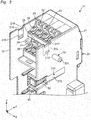
Fig. 2 is a perspective view showing a terminal block of the terminal block set ofFig. 1 . -
Fig. 3 is a partially enlarged view of a periphery of a protruding portion ofFig. 2 . -
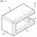
Fig. 4 is a perspective view showing a coupling member of the terminal block set ofFig. 1 . -
Fig. 5 is a side view of the coupling member ofFig. 4 . -
Fig. 6 is a partially enlarged view of a periphery of a coupling accommodating portion ofFig. 2 . -
Fig. 7 is a partially enlarged view ofFig. 6 in a state where the coupling member is removed. -
Fig. 8 is a perspective view showing a first modification of the terminal block ofFig. 2 . -
Fig. 9 is a perspective view showing a second modification of the terminal block ofFig. 2 . - Hereinafter, an example of the present disclosure will be described with reference to the accompanying drawings. In the following description, terms indicating specific directions or positions (for example, terms including "up," "down," "right," and "left") are used as necessary, but the use of these terms is to facilitate understanding of the present disclosure with reference to the drawings, and the technical scope of the present disclosure is not limited by the meanings of these terms. Further, the following description is merely exemplary in nature and is not intended to limit the present disclosure, an object for application, or a usage. Furthermore, the drawings are schematic, and ratios of dimensions and the like do not necessarily match actual ones.
- As shown in
Fig. 1 , a terminal block set 1 of an embodiment of the present disclosure includes a plurality of terminal blocks coupled along a first direction X in an electrically connected state. In the present embodiment, the terminal block set 1 includes, as the plurality of terminal blocks, afirst terminal block 11, asecond terminal block 12, and athird terminal block 13 which are electrically connected to each other. - Hereinafter, a direction intersecting (for example, orthogonal to) the first direction X is referred to as a second direction Y, and a direction intersecting (for example, orthogonal to) the first direction X and the second direction Y is referred to as a third direction Z.
- As shown in
Fig. 2 , each of theterminal blocks insulating housing 20 and a plurality ofterminals 30 arranged inside thehousing 20. Theterminal blocks Fig. 2 , only thefirst terminal block 11 is shown. - As shown in
Fig. 2 , thehousing 20 has a substantially rectangular parallelepiped shape, and includes afirst wall portion 21 provided on one side in the first direction X and extending in the second direction Y, and asecond wall portion 22 provided on the other side in the first direction X and extending in the second direction Y. Thefirst wall portion 21 and thesecond wall portion 22 each have a substantially rectangular shape when viewed from the first direction X, and are arranged substantially parallel to each other at an interval in the first direction X. - The
first wall portion 21 includes a protrudingportion 23 protruding from thefirst wall portion 21 in the first direction X and in a direction away from thesecond wall portion 22. Theprotruding portion 23 is formed of a substantially columnar protrudingmember 231, and is arranged in the vicinity of an imaginary straight line L1 (shown inFig. 1 ) extending in the first direction X through an input-sidepower supply terminal 31 described later when viewed from the third direction Z. In the present embodiment, theprotruding portion 23 is provided at one end in the longitudinal direction (that is, the upper end ofFig. 2 ) of the outer surface of thefirst wall portion 21. Thesecond wall portion 22 includes a first throughhole 24 that is arranged in the vicinity of the input-sidepower supply terminal 31 and penetrates thesecond wall portion 22 in the first direction X. Each of theprotruding portion 23 and the first throughhole 24 is arranged on an imaginary straight line L2 (shown inFig. 2 ) extending in the first direction X. - As shown in
Figs. 1 and2 , the plurality ofterminals 30 are provided at both end portions in the second direction Y (that is, in the longitudinal direction of the housing 20). In the present embodiment, eightterminals 30 are arranged in a lattice pattern extending in the first direction X and the second direction Y in regions at both ends of thehousing 20 in the second direction Y. - The
terminals 30 include the input-sidepower supply terminal 31 and output-sidepower supply terminal 32. Each of the input-sidepower supply terminal 31 and the output-sidepower supply terminal 32 is arranged along thesecond wall portion 22 of thehousing 20, and is configured to be connectable to each of an input-side power supply line 2 and an output-side power supply line 3 (both shown inFig. 1 ). In the present embodiment, each of the input-sidepower supply terminal 31 and the output-sidepower supply terminal 32 is arranged along thesecond wall portion 22 in the region on the upper side in the second direction Y of thehousing 20. - As shown in
Fig. 3 , theterminals 30 are independently accommodated in a plurality of accommodating portions (not shown) provided inside thehousing 20. Each accommodating portion communicates with an outside of thehousing 20 via twoopening portions opening portion 25 is configured such that a conductor portion (not shown) of an electric wire can be inserted and removed. Further, the otheropening portion 26 is configured such that a long jig (for example, a flathead screwdriver) can be inserted and removed. InFig. 3 , only thefirst terminal block 11 is shown. - As shown in
Fig. 1 , theprotruding portion 23 of thefirst terminal block 11 is inserted into the first throughhole 24 of thesecond terminal block 12, and overlaps a part or an entirety of theopening portion 25 connected to the accommodating portion in which the input-sidepower supply terminal 31 is accommodated when viewed from the third direction Z (that is, the sheet penetration direction ofFig. 1 ). As a result, the protrudingportion 23 functions as an obstructing member that hinders or obstructs connection of the input-side power supply line 2 of thesecond terminal block 12 to the input-sidepower supply terminal 31. Further, theprotruding portion 23 of thesecond terminal block 12 is inserted into the first throughhole 24 of thethird terminal block 13, and functions as an obstructing member that hinders connection of the input-side power supply line 2 of thesecond terminal block 12 to the input-sidepower supply terminal 31. That is, the first throughhole 24 is configured to allow insertion of an obstructing member. - In addition, as shown in
Fig. 2 , thehousing 20 includes aprotrusion 27 provided on thefirst wall portion 21 and arranged at an interval from the protrudingportion 23 in the second direction Y, and a second throughhole 28 provided on thesecond wall portion 22 and arranged at an interval from the first throughhole 24 in the second direction Y. In the present embodiment, theprotrusion 27 is provided at the other end (that is, the lower end ofFig. 2 ) of thefirst wall portion 21 in the longitudinal direction, and the second throughhole 28 is provided at the other end of thesecond wall portion 22 in the longitudinal direction. Each of theprotrusion 27 and the second throughhole 28 is arranged on an imaginary straight line L3 (shown inFig. 2 ) extending in the first direction X. - As shown in
Fig. 1 , theprotrusion 27 of thefirst terminal block 11 is press-fitted into the second throughhole 28 of thesecond terminal block 12, whereby thefirst terminal block 11 and thesecond terminal block 12 are coupled to each other. Further, theprotrusion 27 of thesecond terminal block 12 is press-fitted into the second throughhole 28 of thethird terminal block 13, whereby thefirst terminal block 11 and thesecond terminal block 12 are coupled to each other. - In the present embodiment, the
protruding portion 23 is configured to be press-fitted into the first throughhole 24, theprotruding portion 23 and theprotrusion 27 constitute a pair of press-fit protrusions, and the first throughhole 24 and the second throughhole 28 constitute a pair of press-fit holes. That is, the protrudingportion 23 also serves as a press-fit protrusion. - As shown in
Fig. 2 , thehousing 20 includes ajig groove 211 extending along the third direction Z from one edge of thefirst wall portion 21 in the third direction Z (that is, an edge of thefirst wall portion 21 on the side where theopening portion portions housing 20 are opened). In the present embodiment, the twojig grooves 211 are arranged between the protrudingportion 23 and theprotrusion 27 in the second direction Y and in the vicinities of the protrudingportion 23 and theprotrusion 27, respectively. - As shown in
Fig. 3 , eachjig groove 211 includes abottom surface 212 facing the adjacent terminal block, and is configured to allow insertion of a long jig (for example, a flathead screwdriver). Thebottom surface 212 of eachjig groove 211 is inclined so as to approach the adjacent terminal block from one edge toward the other edge in the third direction Z. - According to the terminal blocks 11, 12, and 13, the
housing 20 includes the protrudingportion 23 that protrudes from thefirst wall portion 21 in the first direction X and in the direction away from thesecond wall portion 22 and functions as an obstructing member that hinders connection of the input-side power supply line 2 to the input-sidepower supply terminal 31, and the throughhole 24 that is arranged in the vicinity of the input-side power supply line 2 of thesecond wall portion 22 and penetrates thesecond wall portion 22 in the first direction X to allow insertion of the obstructing member. With such a configuration, for example, when the firstterminal block 11, the secondterminal block 12, and the thirdterminal block 13 are coupled along the first direction, the protrudingportion 23 of the firstterminal block 11 prevents connection of the input-side power supply line 2 to the input-sidepower supply terminal 31 of the secondterminal block 12, and the protrudingportion 23 of the secondterminal block 12 prevents connection of the input-side power supply line 2 to the input-sidepower supply terminal 31 of the thirdterminal block 13. As a result, it is possible to realize the terminal blocks 11, 12, and 13 capable of preventing erroneous connection to thepower supply terminal 31 when the plurality of the terminal blocks are coupled in an electrically connected state. - According to the terminal block set 1, the terminal blocks 11, 12, and 13 can realize the terminal block set 1 capable of preventing erroneous connection to the
power supply terminal 31. - The
housing 20 of the firstterminal block 11 includes the pair of press-fit protrusions first wall portion 21. Thehousing 20 of the secondterminal block 12 includes the pair of press-fit holes second wall portion 22 and penetrating thesecond wall portion 22 in the first direction X. Each of the pair of press-fit protrusions fit holes fit protrusions portion 23. With such a configuration, it is possible to more reliably hold the coupling between the adjacent terminal blocks 11 and 12 of the terminal block set 1. - The
housing 20 of the firstterminal block 11 includes thejig groove 211 that extend along the third direction Z from one edge of thefirst wall portion 21 in the third direction Z intersecting the first direction X and the second direction Y, thejig groove 211 allowing insertion of a long jig. With such a configuration, for example, by inserting a long jig into eachjig groove 211 of the firstterminal block 11 of the terminal block set 1, the coupling between the adjacent terminal blocks 11, 12, and 13 (for example, between firstterminal block 11 and secondterminal block 12 adjacent to first terminal block 11) can be easily released. - The
jig groove 211 includes thebottom surface 212 that faces the secondterminal block 12 and is inclined so as to approach the secondterminal block 12 from one edge toward the other edge in the third direction Z. With such a configuration, for example, it is possible to more easily release the coupling between the adjacent terminal blocks 11, 12, and 13 (for example, between the firstterminal block 11 and the secondterminal block 12 adjacent to first terminal block 11) of the terminal block set 1 using a long jig. - As shown in
Fig. 1 , the terminal block set 1 further includes a C-shapedcoupling member 40 that couple and hold the adjacent terminal blocks 11, 12, and 13. In the present embodiment, the terminal block set 1 includes fourcoupling members 40. Twocoupling members 40 of the fourcoupling members 40 sandwich thefirst wall portion 21 of thehousing 20 of the firstterminal block 11 and thesecond wall portion 22 of thehousing 20 of the secondterminal block 12 at both ends in the second direction Y, respectively. The remaining twocoupling members 40 of the fourcoupling members 40 sandwich thefirst wall portion 21 of thehousing 20 of the secondterminal block 12 and thesecond wall portion 22 of thehousing 20 of the thirdterminal block 13 at both ends in the second direction Y, respectively. - Specifically, as shown in
Figs. 4 and5 , thecoupling member 40 includes a pair of plate-shapedarm portions 41 that extend such that a plate surface of the pair ofarm portions 41 faces each other and is elastically deformable in a direction away from each other, and a connectingportion 42 that connects the pair ofarm portions 41. Eacharm portion 41 includes acoupling protrusion 43 provided at an end portion farther from the connectingportion 42 in an extending direction of eacharm portion 41. - The coupling protrusions 43 each have a substantially semi-cylindrical shape and protrude in a direction approaching each other. One of the
coupling protrusions 43 is accommodated in afirst accommodation hole 213 of the firstterminal block 11 or the secondterminal block 12 described later, and the other of thecoupling protrusions 43 is accommodated in asecond accommodation hole 214 of the secondterminal block 12 or the thirdterminal block 13 described later. A movement of thecoupling member 40 in the second direction Y is restricted by accommodating thecoupling protrusions 43 in thefirst accommodation hole 213 and thesecond accommodation hole 214. - As shown in
Fig. 3 , thehousing 20 of each of the terminal blocks 11, 12, and 13 includes thefirst accommodation hole 213 and thesecond accommodation hole 214 capable of accommodating thecoupling protrusions 43 of thecoupling members 40, and afirst accommodation groove 215 and asecond accommodation groove 216 that guide thecoupling protrusions 43 of thecoupling members 40 to each of the accommodation holes 213 and 214. - The
first accommodation groove 215 is provided on a surface of thefirst wall portion 21 facing thesecond wall portion 22, and extends from an edge of thefirst wall portion 21 in a direction intersecting the first direction X toward thefirst accommodation hole 213. In the present embodiment, thefirst accommodation groove 215 extends toward thefirst accommodation hole 213 along the second direction Y from anotch 217 provided at the edge of thefirst wall portion 21 closer to thefirst accommodation hole 213 in the second direction Y. Thesecond accommodation groove 216 is provided on a surface of thesecond wall portion 22 facing thefirst wall portion 21, and extends from an edge of thesecond wall portion 22 in the direction intersecting the first direction X toward thesecond accommodation hole 214. In the present embodiment, thesecond accommodation groove 216 extends toward thesecond accommodation hole 214 along the second direction Y from anotch 218 provided at the edge of thesecond wall portion 22 closer to thesecond accommodation hole 214 in the second direction Y. - One of the pair of
arm portions 41 of thecoupling member 40 is accommodated in thefirst accommodation groove 215, and the other of the pair ofarm portions 41 of thecoupling member 40 is accommodated in thesecond accommodation groove 216. Thus, a movement of thecoupling member 40 in the third direction Z is restricted. - As shown in
Fig. 2 , thehousing 20 of each of the terminal blocks 11, 12, and 13 includes acoupling accommodating portion 50 that accommodate thecoupling member 40. In the present embodiment, thehousing 20 of each of the terminal blocks 11, 12, and 13 includes two couplingaccommodating portions 50 arranged at an interval in the second direction Y. Eachcoupling accommodating portion 50 is provided at an end portion of thehousing 20 on the side where the openingportions first wall portion 21 of thehousing 20. InFig. 2 , a state in which thecoupling members 40 are accommodated in thecoupling accommodating portions 50 of the firstterminal block 11 is shown. - Specifically, as shown in
Figs. 6 and7 , thecoupling accommodating portion 50 includes a pair of first recessedportions 51 capable of accommodating the pair of arm portions of thecoupling member 40, and a second recessedportion 52 arranged between the pair of first recessedportions 51 and capable of accommodating the connectingportion 42 of thecoupling member 40. - Each of the first recessed
portions 51 has a substantially rectangular parallelepiped shape and includes a substantially L-shapedopening portion 511 extending in the first direction X and the third direction Z. Thejig groove 211 of thefirst wall portion 21 is connected to theopening portion 511 of each of the first recessedportions 51. AGroove 53 extending in a rail shape in the first direction X is provided on an inner surface of the first recessedportions 51 facing each other in the second direction Y. Eachgroove 53 has a substantially semicircular shape, and is configured to be able to accommodate thecoupling protrusion 43 of eacharm portion 41 of thecoupling member 40. - The second recessed
portion 52 includes a recessed-portionmain body 521 that accommodates the connectingportion 42 of thecoupling member 40, and aninclined surface 522 extending from the recessed-portionmain body 521 in a direction intersecting the arrangement direction of the pair of first recessed portions 51 (that is, the second direction Y). In the present embodiment, the second recessedportion 52 has twoinclined surfaces 522 extending in directions away from each other from both ends of the recessed-portionmain body 521 in the second direction Y. - Each
inclined surface 522 is inclined in a direction away from the bottom surface of the recessed-portion main body 521 (that is, upward in the third direction Z ofFigs. 6 and7 ) as being away from the recessed-portionmain body 521. Eachinclined surface 522 guides a long jig (for example, a flathead screwdriver) between the connectingportion 42 of thecoupling member 40 and the recessed-portionmain body 521, so that thecoupling member 40 accommodated in thecoupling accommodating portion 50 can be easily removed. - The terminal block set 1 includes the C-shaped
coupling members 40 that each sandwich, and couple and hold thefirst wall portion 21 of thehousing 20 of the firstterminal block 11 and thesecond wall portion 22 of thehousing 20 of the secondterminal block 12. With such a configuration, since the terminal blocks 11, 12, and 13 adjacent to each other can be coupled and held more reliably, it is possible to realize the terminal block set 1 capable of securing coupling reliability between the terminal blocks 11, 12, and 13 adjacent to each other. - The
coupling member 40 includes the pair of plate-shapedarm portions 41 that extend such that the plate surface of the pair of arm portions faces each other and is elastically deformable in the direction away from each other. The connectingportion 42 that connects the pair ofarm portions 41. Each of thearm portions 41 has thecoupling protrusion 43 provided at the end portion farther from the connectingportion 42 in the extending direction and protruding in the direction approaching each other. Each of thefirst wall portion 21 of the firstterminal block 11 and thesecond wall portion 22 of the secondterminal block 12 has each of thefirst accommodation hole 213 and thesecond accommodation hole 214 in which thecoupling protrusion 43 of eacharm portion 41 is accommodated. With such a configuration, a movement of thecoupling member 40 can be restricted to prevent thecoupling member 40 from unintentionally falling off. - The
first wall portion 21 of the firstterminal block 11 has thefirst accommodation groove 215 that is provided on the surface facing thesecond wall portion 22, extends toward thefirst accommodation hole 213 from the edge of thefirst wall portion 21 in the direction intersecting the first direction X, and accommodates one of the pair ofarm portions 41 of thecoupling member 40. Thesecond wall portion 22 of the secondterminal block 12 has thesecond accommodation groove 216 that is provided on the surface facing thefirst wall portion 21, extends toward thesecond accommodation hole 214 from the edge of thesecond wall portion 22 in the direction intersecting the first direction X, and accommodates the other of the pair ofarm portions 41 of thecoupling member 40. With such a configuration, a movement of thecoupling member 40 can be restricted to prevent thecoupling member 40 from unintentionally falling off. - Each of the
housing 20 of the firstterminal block 11 and thehousing 20 of the secondterminal block 12 includes thecoupling accommodating portion 50 that accommodate thecoupling member 40. With such a configuration, for example, since thecoupling member 40 that is not used can be accommodated in thecoupling accommodating portion 50, the loss of thecoupling member 40 can be prevented. - The
coupling accommodating portion 50 includes the pair of first recessedportions 51 capable of accommodating the pair ofarm portions 41, and the second recessedportion 52 arranged between the pair of first recessedportions 51 and capable of accommodating the connectingportion 42. The second recessedportion 52 includes the recessed-portionmain body 521 that accommodates the connectingportion 42, and theinclined surface 522 that extends from the recessed-portionmain body 521 along the direction intersecting the arrangement direction of the pair of first recessedportions 51 and is inclined in the direction away from the bottom surface of the recessed-portionmain body 521 as being away from the recessed-portionmain body 521. With such a configuration, a long jig (for example, a flathead screwdriver) can be guided between the connectingportion 42 of thecoupling member 40 and the recessed-portionmain body 521, so that thecoupling member 40 accommodated in thecoupling accommodating portion 50 can be easily removed. - The protruding
portion 23 is not limited to a case where it is formed of one substantially columnar protruding member. For example, as shown inFig. 8 , two substantially cylindrical protrudingmembers 231 and 232 (that is, the first protrudingmember 231 and a second protruding member 232) may be used. As a result, the protrudingportion 23 functions as an obstructing member that hinders connection of the input-side power supply line 2 to the input-sidepower supply terminal 31 and hinders connection of the output-sidepower supply line 3 to the output-sidepower supply terminal 32. The second protrudingmember 232 is arranged in the vicinity of an imaginary straight line L4 (shown inFig. 1 ) extending in the first direction X through the output-sidepower supply terminal 32. In addition to a substantially circular throughhole 241 corresponding to the first protrudingmember 231, thesecond wall portion 22 is provided with a substantially circular throughhole 242 corresponding to the second protrudingmember 232. With such a configuration, it is possible to realize the terminal blocks 11, 12, and 13 capable of more reliably preventing erroneous connection to thepower supply terminal 31 when the plurality of the terminal blocks are coupled in an electrically connected state. - The protruding
members member 231 is not limited to a substantially cylindrical shape, and may have a substantially prismatic shape or an elliptical shape. - As shown in
Fig. 9 , the protrudingportion 23 may be constituted by a third protrudingmember 233 that functions as an obstructing member that simultaneously hinders both connection of the input-side power supply line 2 to the input-sidepower supply terminal 31 and connection of the output-sidepower supply line 3 to the output-sidepower supply terminal 32. InFig. 9 , as an example, the third protrudingmember 233 having a substantially rectangular plate shape is shown. Both end portions of the third protrudingmember 233 in the second direction Y are arranged near the imaginary straight lines L1 and L3, respectively. Thesecond wall portion 22 is provided with a through hole 243 having a substantially rectangular shape corresponding to the third protrudingmember 233. With such a configuration, it is possible to realize the terminal blocks 11, 12, and 13 capable of more reliably preventing erroneous connection to thepower supply terminal 31 when the plurality of the terminal blocks are coupled in an electrically connected state. - That is, the protruding
portion 23 only needs to function as an obstructing member that hinders at least connection of the input-side power supply line 2 to the input-sidepower supply terminal 31, and any shape, size, and configuration can be adopted in accordance with the design of the terminal block set 1 and the like. - Each of the terminal blocks 11, 12, and 13 is not limited to the above embodiment, and can be optionally configured in accordance with a design of the terminal block set 1 or the like as long as it includes the
housing 20 including thefirst wall portion 21 and thesecond wall portion 22, and the input-sidepower supply terminal 31 and the output-sidepower supply terminal 32 arranged inside thehousing 20. The terminal blocks 11, 12, and 13 may be electrically disconnected when coupled to each other. - The
coupling member 40 only needs to have a C shape and be capable of sandwiching, and coupling and holding thefirst wall portion 21 of the terminal block (for example, first terminal block 11) and thesecond wall portion 22 of the terminal block (for example, second terminal block 12) adjacent to the terminal block, and can be optionally configured in accordance with a design of the terminal block set 1 or the like. - The
coupling accommodating portion 50 only needs to accommodate thecoupling member 40, and can be optionally configured in accordance with a design of the terminal block set 1 or the like. - The
coupling accommodating portion 50, the accommodation holes 213 and 214, and theaccommodation grooves - The protruding
portion 23 does not need to also serve as the press-fit protrusion, and the press-fit protrusion may be separately provided. - The protruding
portion 23 and the protrusion 27 (that is, the pair of press-fit protrusions), the throughholes 24 and 28 (that is, the pair of press-fitting holes), and thejig grooves 211 can be omitted. - Various embodiments of the present disclosure have been described above in detail with reference to the drawings. Finally, various aspects of the present disclosure will be described. In the following description, as an example, reference numerals are also added.
- A terminal block set 1 of a first aspect of the present disclosure, in which a plurality of terminal blocks 11, 12, and 13 are coupled along a first direction X, each of the terminal blocks 11, 12, and 13 including a
housing 20 that includes afirst wall portion 21 provided on one side in the first direction X and asecond wall portion 22 provided on the other side in the first direction X, includes: - a first
terminal block 11 and a secondterminal block 12 adjacent to the firstterminal block 11 as the plurality of terminal blocks 11, 12, and 13; and - a C-shaped
coupling member 40 that sandwiches, and couples and holds thefirst wall portion 21 of thehousing 20 of the firstterminal block 11 and thesecond wall portion 22 of thehousing 20 of the secondterminal block 12. - The terminal block set 1 of the first aspect includes the C-shaped
coupling member 40 that sandwiches, and couples and holds thefirst wall portion 21 of thehousing 20 of the firstterminal block 11 and thesecond wall portion 22 of thehousing 20 of the secondterminal block 12. With such a configuration, since the terminal blocks 11, 12, and 13 adjacent to each other can be coupled and held more reliably, it is possible to realize the terminal block set 1 capable of securing coupling reliability between the terminal blocks 11, 12, and 13 adjacent to each other. - In the terminal block set 1 of a second aspect of the present disclosure,
- the
coupling member 40 includes: - a pair of plate-shaped
arm portions 41 that extend such that a plate surface of the pair of arm portions faces each other and is elastically deformable in a direction away from each other; and - a connecting
portion 42 that connects the pair ofarm portions 41, - each of the pair of
arm portions 41 includes acoupling protrusion 43 provided at an end portion farther from the connectingportion 42 in an extending direction thereof, thecoupling protrusion 43 protruding in a direction approaching each other, and - each of the
first wall portion 21 of the firstterminal block 11 and thesecond wall portion 22 of the secondterminal block 12 includes afirst accommodation hole 213 and asecond accommodation hole 214 in which thecoupling protrusions 43 of the pair ofarm portions 41 are accommodated, respectively. - According to the terminal block set 1 of the second aspect, a movement of the
coupling member 40 can be restricted to prevent thecoupling member 40 from unintentionally falling off. - In a terminal block set 1 of a third aspect of the present disclosure,
- the
first wall portion 21 of the firstterminal block 11 includes afirst accommodation groove 215 that is provided on a surface facing thesecond wall portion 22, extends toward thefirst accommodation hole 213 from an edge of thefirst wall portion 21 in a direction intersecting the first direction X, and accommodates one of the pair ofarm portions 41 of thecoupling member 40, and - the
second wall portion 22 of the secondterminal block 12 includes asecond accommodation groove 216 that is provided on a surface facing thefirst wall portion 21, extends toward thesecond accommodation hole 214 from an edge of thesecond wall portion 22 in the direction intersecting the first direction X, and accommodates the other of the pair ofarm portions 41 of thecoupling member 40. - According to the terminal block set 1 of the third aspect, a movement of the
coupling member 40 can be restricted to prevent thecoupling member 40 from unintentionally falling off. - In a terminal block set 1 of a fourth aspect of the present disclosure,
- the
housing 20 of the firstterminal block 11 includes a pair of press-fit protrusions first wall portion 21, - the
housing 20 of the secondterminal block 12 includes a pair of press-fit holes second wall portion 22 and penetrating thesecond wall portion 22 in the first direction X, and - each of the pair of press-
fit protrusions fit holes - According to the terminal block set 1 of the fourth aspect, it is possible to more reliably hold the coupling between the adjacent terminal blocks 11, 12, and 13 of the terminal block set 1.
- In a terminal block set 1 of a fifth aspect of the present disclosure,
each of thehousing 20 of the firstterminal block 11 and thehousing 20 of the secondterminal block 12 includes acoupling accommodating portion 50 that accommodates thecoupling member 40. - According to a terminal block set 1 of a fifth aspect, for example, since the
coupling member 40 that is not used can be accommodated in thecoupling accommodating portion 50, the loss of thecoupling member 40 can be prevented. - In a terminal block set 1 of a sixth aspect of the present disclosure,
- the
coupling member 40 includes: - a pair of plate-shaped
arm portions 41 that extend such that a plate surface of the pair of plate-shapedarm portions 41 faces each other and is elastically deformable in a direction away from each other; and - a connecting
portion 42 that connects the pair of arm portions, - the
coupling accommodating portion 50 includes:- a pair of first recessed
portions 51 capable of accommodating the pair ofarm portions 41; and - a second recessed
portion 52 arranged between the pair of first recessedportions 51 and capable of accommodating the connectingportion 42, and - the second recessed
portion 52 includes: - a recessed-portion
main body 521 that accommodates the connectingportion 42; and - an
inclined surface 522 that extends from the recessed-portionmain body 521 along a direction intersecting an arrangement direction of the pair of first recessedportions 51 and is inclined in a direction away from a bottom surface of the recessed-portionmain body 521 as being away from the recessed-portionmain body 521.
- a pair of first recessed
- According to the terminal block set 1 of the sixth aspect, for example, a long jig (for example, a flathead screwdriver) can be guided between the connecting
portion 42 of thecoupling member 40 and the recessed-portionmain body 521, so that thecoupling member 40 accommodated in thecoupling accommodating portion 50 can be easily removed. - By appropriately combining any embodiments or modifications among the various embodiments or modifications, the effects of the respective embodiments or modifications can be achieved. In addition, combinations of embodiments, combinations of examples, or combinations of embodiments and examples are possible, and combinations of features in different embodiments or examples are also possible.
- Although the present disclosure has been fully described in connection with preferred embodiments with reference to the accompanying drawings, various modifications and corrections will be apparent to those skilled in the art. Such modifications and corrections are to be understood as being included within the scope of the present disclosure as set forth in the appended claims.
- The terminal blocks and the terminal block set of the present disclosure can be used for, for example, a temperature regulator of a control panel.
-
- 1.
- terminal block set
- 2.
- input-side power supply line
- 3.
- output-side power supply line
- 11, 12, 13.
- terminal block
- 20.
- housing
- 21.
- first wall portion
- 211.
- jig groove
- 212.
- bottom surface
- 213, 214.
- accommodation hole
- 215, 216.
- accommodation groove
- 217, 218.
- notch
- 22.
- second wall portion
- 23.
- protruding portion
- 231, 232, 233.
- protruding member
- 24, 241, 242, 243.
- through hole
- 25, 26.
- opening portion
- 27.
- protrusion
- 28.
- through hole
- 30.
- terminal
- 31.
- input-side power supply terminal
- 32.
- output-side power supply terminal
- 40.
- coupling member
- 41.
- arm portion
- 42.
- connecting portion
- 43.
- coupling protrusion
- 50.
- coupling accommodating portion
- 51.
- first recessed portion
- 511.
- opening portion
- 52.
- second recessed portion
- 521.
- recessed-portion main body
- 522.
- inclined surface
- X.
- first direction
- Y.
- second direction
- Z.
- third direction
- L1 to L4.
- imaginary straight line
Claims (6)
- A terminal block set in which a plurality of terminal blocks are coupled along a first direction, each of the terminal blocks including a housing that includes a first wall portion provided on a first side in the first direction and a second wall portion provided on a second side in the first direction, the terminal block comprising:a first terminal block and a second terminal block adjacent to the first terminal block as the plurality of terminal blocks; anda C-shaped coupling member that sandwiches, and couples and holds the first wall portion of the housing of the first terminal block and the second wall portion of the housing of the second terminal block.
- The terminal block set according to claim 1, wherein
the coupling member includes:a pair of plate-shaped arm portions that extend such that a plate surface of the pair of arm portions faces each other and is elastically deformable in a direction away from each other; anda connecting portion that connects the pair of arm portions,each of the pair of arm portions includes a coupling protrusion provided at an end portion farther from the connecting portion in an extending direction thereof, the coupling protrusion protruding in a direction approaching each other, andeach of the first wall portion of the first terminal block and the second wall portion of the second terminal block includes a first accommodation hole and a second accommodation hole in which the coupling protrusions of the pair of arm portions are accommodated, respectively. - The terminal block set according to claim 2, whereinthe first wall portion of the first terminal block includes a first accommodation groove that is provided on a surface facing the second wall portion, extends toward the first accommodation hole from an edge of the first wall portion in a direction intersecting the first direction, and accommodates one of the pair of arm portions of the coupling member, andthe second wall portion of the second terminal block includes a second accommodation groove that is provided on a surface facing the first wall portion, extends toward the second accommodation hole from an edge of the second wall portion in the direction intersecting the first direction, and accommodates another of the pair of arm portions of the coupling member.
- The terminal block set according to any one of claims 1 to 3, whereinthe housing of the first terminal block includes a pair of press-fit protrusions arranged at an interval in a second direction intersecting the first direction of the first wall portion,the housing of the second terminal block includes a pair of press-fit holes provided on the second wall portion and penetrating the second wall portion in the first direction, andeach of the pair of press-fit protrusions is configured to be press-fit into each of the pair of press-fit holes.
- The terminal block set according to any one of claims 1 to 4, wherein
each of the housing of the first terminal block and the housing of the second terminal block includes a coupling accommodating portion that accommodates the coupling member. - The terminal block set according to claim 5,
whereinthe coupling member includes:a pair of plate-shaped arm portions that extend such that a plate surface of the pair of plate-shaped arm portions faces each other and is elastically deformable in a direction away from each other; anda connecting portion that connects the pair of arm portions,the coupling accommodating portion includes:a pair of first recessed portions capable of accommodating the pair of arm portions; anda second recessed portion arranged between the pair of first recessed portions and capable of accommodating the connecting portion, andthe second recessed portion includes:a recessed-portion main body that accommodates the connecting portion; andan inclined surface that extends from the recessed-portion main body along a direction intersecting an arrangement direction of the pair of first recessed portions and is inclined in a direction away from a bottom surface of the recessed-portion main body as being away from the recessed-portion main body.
Applications Claiming Priority (2)
| Application Number | Priority Date | Filing Date | Title |
|---|---|---|---|
| JP2018234669A JP7001047B2 (en) | 2018-12-14 | 2018-12-14 | Terminal block |
| PCT/JP2019/047838 WO2020121969A1 (en) | 2018-12-14 | 2019-12-06 | Terminal block |
Publications (2)
| Publication Number | Publication Date |
|---|---|
| EP3876354A1 true EP3876354A1 (en) | 2021-09-08 |
| EP3876354A4 EP3876354A4 (en) | 2022-08-03 |
Family
ID=71076855
Family Applications (1)
| Application Number | Title | Priority Date | Filing Date |
|---|---|---|---|
| EP19897112.9A Pending EP3876354A4 (en) | 2018-12-14 | 2019-12-06 | TERMINAL |
Country Status (6)
| Country | Link |
|---|---|
| US (1) | US12074405B2 (en) |
| EP (1) | EP3876354A4 (en) |
| JP (1) | JP7001047B2 (en) |
| KR (1) | KR102572554B1 (en) |
| CN (1) | CN113169467B (en) |
| WO (1) | WO2020121969A1 (en) |
Families Citing this family (1)
| Publication number | Priority date | Publication date | Assignee | Title |
|---|---|---|---|---|
| JP6962309B2 (en) * | 2018-12-14 | 2021-11-05 | オムロン株式会社 | Terminal block and terminal block set |
Family Cites Families (10)
| Publication number | Priority date | Publication date | Assignee | Title |
|---|---|---|---|---|
| FR2621424B1 (en) | 1987-10-02 | 1992-12-31 | Merlin Gerin | MECHANICAL ASSEMBLY DEVICE WITH SELF-CENTERING OF ELECTRICAL EQUIPMENT MODULES |
| DE4402002B4 (en) * | 1994-01-18 | 2005-10-27 | Wago Verwaltungsgesellschaft Mbh | I / O modules / for a data bus |
| US5839922A (en) * | 1997-03-24 | 1998-11-24 | Ortronics, Inc. | 110 wiring block interlock and interlocked blocks utilizing such |
| JP2000231950A (en) | 1999-02-12 | 2000-08-22 | Nitto Electric Works Ltd | Terminal block |
| JP2002305828A (en) * | 2001-04-03 | 2002-10-18 | Sumitomo Wiring Syst Ltd | Structure for fixing connector housing to electrical junction box |
| DE102007033942B4 (en) * | 2007-07-19 | 2009-08-27 | Phoenix Contact Gmbh & Co. Kg | Electrical terminal |
| US7553199B2 (en) * | 2007-07-31 | 2009-06-30 | Phoenix Contact Development & Manufacturing, Inc. | Modular terminal block |
| JP5666232B2 (en) | 2010-10-01 | 2015-02-12 | 矢崎総業株式会社 | Terminal connection structure |
| DE102014101528A1 (en) * | 2014-02-07 | 2015-08-13 | Phoenix Contact Gmbh & Co. Kg | Honeycomb module and maneuvering comb |
| JP6784483B2 (en) | 2015-07-24 | 2020-11-11 | 東朋テクノロジー株式会社 | Sensor terminal block and terminal block unit |
-
2018
- 2018-12-14 JP JP2018234669A patent/JP7001047B2/en active Active
-
2019
- 2019-12-06 US US17/312,716 patent/US12074405B2/en active Active
- 2019-12-06 KR KR1020217015541A patent/KR102572554B1/en active Active
- 2019-12-06 WO PCT/JP2019/047838 patent/WO2020121969A1/en not_active Ceased
- 2019-12-06 EP EP19897112.9A patent/EP3876354A4/en active Pending
- 2019-12-06 CN CN201980079061.2A patent/CN113169467B/en active Active
Also Published As
| Publication number | Publication date |
|---|---|
| KR102572554B1 (en) | 2023-08-30 |
| JP2020095915A (en) | 2020-06-18 |
| CN113169467A (en) | 2021-07-23 |
| JP7001047B2 (en) | 2022-01-19 |
| US20220021135A1 (en) | 2022-01-20 |
| KR20210073585A (en) | 2021-06-18 |
| US12074405B2 (en) | 2024-08-27 |
| EP3876354A4 (en) | 2022-08-03 |
| CN113169467B (en) | 2023-04-21 |
| WO2020121969A1 (en) | 2020-06-18 |
Similar Documents
| Publication | Publication Date | Title |
|---|---|---|
| US11870200B2 (en) | Terminal block and terminal block set | |
| CN110277659B (en) | Connecting piece and socket | |
| US10498077B2 (en) | Power connector and power connector device | |
| JP2017010759A (en) | Joint connector | |
| CN105075033A (en) | Assembly structure for electronic component, and electronic component | |
| US12074405B2 (en) | Terminal block set including terminal blocks connected to each other | |
| CN105830298B (en) | Circuit arrangement | |
| US8507809B2 (en) | Component-equipped-holder mounting structure | |
| EP3940736B1 (en) | Terminal block | |
| CN111448717A (en) | Terminals and Connectors for Connectors | |
| JP2020092577A (en) | Electric connection box | |
| JP7006575B2 (en) | Terminal module and terminal block | |
| EP3879632A1 (en) | Terminal block | |
| KR20230117507A (en) | Socket |
Legal Events
| Date | Code | Title | Description |
|---|---|---|---|
| STAA | Information on the status of an ep patent application or granted ep patent |
Free format text: STATUS: THE INTERNATIONAL PUBLICATION HAS BEEN MADE |
|
| PUAI | Public reference made under article 153(3) epc to a published international application that has entered the european phase |
Free format text: ORIGINAL CODE: 0009012 |
|
| STAA | Information on the status of an ep patent application or granted ep patent |
Free format text: STATUS: REQUEST FOR EXAMINATION WAS MADE |
|
| 17P | Request for examination filed |
Effective date: 20210602 |
|
| AK | Designated contracting states |
Kind code of ref document: A1 Designated state(s): AL AT BE BG CH CY CZ DE DK EE ES FI FR GB GR HR HU IE IS IT LI LT LU LV MC MK MT NL NO PL PT RO RS SE SI SK SM TR |
|
| DAV | Request for validation of the european patent (deleted) | ||
| DAX | Request for extension of the european patent (deleted) | ||
| REG | Reference to a national code |
Ref country code: DE Ref legal event code: R079 Free format text: PREVIOUS MAIN CLASS: H01R0009240000 Ipc: H01R0009260000 |
|
| A4 | Supplementary search report drawn up and despatched |
Effective date: 20220630 |
|
| RIC1 | Information provided on ipc code assigned before grant |
Ipc: H02B 1/04 20060101ALI20220624BHEP Ipc: H01R 9/26 20060101AFI20220624BHEP |
|
| STAA | Information on the status of an ep patent application or granted ep patent |
Free format text: STATUS: EXAMINATION IS IN PROGRESS |
|
| 17Q | First examination report despatched |
Effective date: 20240703 |
|
| GRAP | Despatch of communication of intention to grant a patent |
Free format text: ORIGINAL CODE: EPIDOSNIGR1 |
|
| STAA | Information on the status of an ep patent application or granted ep patent |
Free format text: STATUS: GRANT OF PATENT IS INTENDED |
|
| RIC1 | Information provided on ipc code assigned before grant |
Ipc: H01R 9/26 20060101AFI20260305BHEP |
|
| RIC1 | Information provided on ipc code assigned before grant |
Ipc: H01R 9/26 20060101AFI20260309BHEP Ipc: H01R 9/24 20060101ALI20260309BHEP |
|
| INTG | Intention to grant announced |
Effective date: 20260318 |