EP3876305B1 - Battery module - Google Patents
Battery module Download PDFInfo
- Publication number
- EP3876305B1 EP3876305B1 EP19879488.5A EP19879488A EP3876305B1 EP 3876305 B1 EP3876305 B1 EP 3876305B1 EP 19879488 A EP19879488 A EP 19879488A EP 3876305 B1 EP3876305 B1 EP 3876305B1
- Authority
- EP
- European Patent Office
- Prior art keywords
- copper
- aluminum
- connection face
- portions
- flat
- Prior art date
- Legal status (The legal status is an assumption and is not a legal conclusion. Google has not performed a legal analysis and makes no representation as to the accuracy of the status listed.)
- Active
Links
Images


Classifications
-
- H—ELECTRICITY
- H01—ELECTRIC ELEMENTS
- H01M—PROCESSES OR MEANS, e.g. BATTERIES, FOR THE DIRECT CONVERSION OF CHEMICAL ENERGY INTO ELECTRICAL ENERGY
- H01M50/00—Constructional details or processes of manufacture of the non-active parts of electrochemical cells other than fuel cells, e.g. hybrid cells
- H01M50/50—Current conducting connections for cells or batteries
- H01M50/502—Interconnectors for connecting terminals of adjacent batteries; Interconnectors for connecting cells outside a battery casing
- H01M50/507—Interconnectors for connecting terminals of adjacent batteries; Interconnectors for connecting cells outside a battery casing comprising an arrangement of two or more busbars within a container structure, e.g. busbar modules
-
- H—ELECTRICITY
- H01—ELECTRIC ELEMENTS
- H01M—PROCESSES OR MEANS, e.g. BATTERIES, FOR THE DIRECT CONVERSION OF CHEMICAL ENERGY INTO ELECTRICAL ENERGY
- H01M50/00—Constructional details or processes of manufacture of the non-active parts of electrochemical cells other than fuel cells, e.g. hybrid cells
- H01M50/20—Mountings; Secondary casings or frames; Racks, modules or packs; Suspension devices; Shock absorbers; Transport or carrying devices; Holders
- H01M50/204—Racks, modules or packs for multiple batteries or multiple cells
- H01M50/207—Racks, modules or packs for multiple batteries or multiple cells characterised by their shape
- H01M50/209—Racks, modules or packs for multiple batteries or multiple cells characterised by their shape adapted for prismatic or rectangular cells
-
- H—ELECTRICITY
- H01—ELECTRIC ELEMENTS
- H01M—PROCESSES OR MEANS, e.g. BATTERIES, FOR THE DIRECT CONVERSION OF CHEMICAL ENERGY INTO ELECTRICAL ENERGY
- H01M50/00—Constructional details or processes of manufacture of the non-active parts of electrochemical cells other than fuel cells, e.g. hybrid cells
- H01M50/50—Current conducting connections for cells or batteries
- H01M50/502—Interconnectors for connecting terminals of adjacent batteries; Interconnectors for connecting cells outside a battery casing
- H01M50/503—Interconnectors for connecting terminals of adjacent batteries; Interconnectors for connecting cells outside a battery casing characterised by the shape of the interconnectors
-
- H—ELECTRICITY
- H01—ELECTRIC ELEMENTS
- H01M—PROCESSES OR MEANS, e.g. BATTERIES, FOR THE DIRECT CONVERSION OF CHEMICAL ENERGY INTO ELECTRICAL ENERGY
- H01M50/00—Constructional details or processes of manufacture of the non-active parts of electrochemical cells other than fuel cells, e.g. hybrid cells
- H01M50/50—Current conducting connections for cells or batteries
- H01M50/502—Interconnectors for connecting terminals of adjacent batteries; Interconnectors for connecting cells outside a battery casing
- H01M50/514—Methods for interconnecting adjacent batteries or cells
- H01M50/516—Methods for interconnecting adjacent batteries or cells by welding, soldering or brazing
-
- H—ELECTRICITY
- H01—ELECTRIC ELEMENTS
- H01M—PROCESSES OR MEANS, e.g. BATTERIES, FOR THE DIRECT CONVERSION OF CHEMICAL ENERGY INTO ELECTRICAL ENERGY
- H01M50/00—Constructional details or processes of manufacture of the non-active parts of electrochemical cells other than fuel cells, e.g. hybrid cells
- H01M50/50—Current conducting connections for cells or batteries
- H01M50/502—Interconnectors for connecting terminals of adjacent batteries; Interconnectors for connecting cells outside a battery casing
- H01M50/521—Interconnectors for connecting terminals of adjacent batteries; Interconnectors for connecting cells outside a battery casing characterised by the material
- H01M50/522—Inorganic material
-
- H—ELECTRICITY
- H01—ELECTRIC ELEMENTS
- H01M—PROCESSES OR MEANS, e.g. BATTERIES, FOR THE DIRECT CONVERSION OF CHEMICAL ENERGY INTO ELECTRICAL ENERGY
- H01M50/00—Constructional details or processes of manufacture of the non-active parts of electrochemical cells other than fuel cells, e.g. hybrid cells
- H01M50/50—Current conducting connections for cells or batteries
- H01M50/543—Terminals
- H01M50/547—Terminals characterised by the disposition of the terminals on the cells
- H01M50/55—Terminals characterised by the disposition of the terminals on the cells on the same side of the cell
-
- H—ELECTRICITY
- H01—ELECTRIC ELEMENTS
- H01M—PROCESSES OR MEANS, e.g. BATTERIES, FOR THE DIRECT CONVERSION OF CHEMICAL ENERGY INTO ELECTRICAL ENERGY
- H01M50/00—Constructional details or processes of manufacture of the non-active parts of electrochemical cells other than fuel cells, e.g. hybrid cells
- H01M50/50—Current conducting connections for cells or batteries
- H01M50/543—Terminals
- H01M50/552—Terminals characterised by their shape
- H01M50/553—Terminals adapted for prismatic, pouch or rectangular cells
-
- H—ELECTRICITY
- H01—ELECTRIC ELEMENTS
- H01M—PROCESSES OR MEANS, e.g. BATTERIES, FOR THE DIRECT CONVERSION OF CHEMICAL ENERGY INTO ELECTRICAL ENERGY
- H01M50/00—Constructional details or processes of manufacture of the non-active parts of electrochemical cells other than fuel cells, e.g. hybrid cells
- H01M50/50—Current conducting connections for cells or batteries
- H01M50/543—Terminals
- H01M50/564—Terminals characterised by their manufacturing process
- H01M50/566—Terminals characterised by their manufacturing process by welding, soldering or brazing
-
- H—ELECTRICITY
- H01—ELECTRIC ELEMENTS
- H01M—PROCESSES OR MEANS, e.g. BATTERIES, FOR THE DIRECT CONVERSION OF CHEMICAL ENERGY INTO ELECTRICAL ENERGY
- H01M50/00—Constructional details or processes of manufacture of the non-active parts of electrochemical cells other than fuel cells, e.g. hybrid cells
- H01M50/50—Current conducting connections for cells or batteries
- H01M50/569—Constructional details of current conducting connections for detecting conditions inside cells or batteries, e.g. details of voltage sensing terminals
-
- H—ELECTRICITY
- H01—ELECTRIC ELEMENTS
- H01M—PROCESSES OR MEANS, e.g. BATTERIES, FOR THE DIRECT CONVERSION OF CHEMICAL ENERGY INTO ELECTRICAL ENERGY
- H01M2220/00—Batteries for particular applications
- H01M2220/20—Batteries in motive systems, e.g. vehicle, ship, plane
-
- Y—GENERAL TAGGING OF NEW TECHNOLOGICAL DEVELOPMENTS; GENERAL TAGGING OF CROSS-SECTIONAL TECHNOLOGIES SPANNING OVER SEVERAL SECTIONS OF THE IPC; TECHNICAL SUBJECTS COVERED BY FORMER USPC CROSS-REFERENCE ART COLLECTIONS [XRACs] AND DIGESTS
- Y02—TECHNOLOGIES OR APPLICATIONS FOR MITIGATION OR ADAPTATION AGAINST CLIMATE CHANGE
- Y02E—REDUCTION OF GREENHOUSE GAS [GHG] EMISSIONS, RELATED TO ENERGY GENERATION, TRANSMISSION OR DISTRIBUTION
- Y02E60/00—Enabling technologies; Technologies with a potential or indirect contribution to GHG emissions mitigation
- Y02E60/10—Energy storage using batteries
Definitions
- the present invention relates to battery modules each having a plurality of battery cells.
- Patent Literature 1 describes a busbar including a copper part (701) that is laser welded to a negative electrode group and is made of a copper material, and an aluminum part (702) that is laser welded to a cell positive electrode group and is made of aluminum.
- This busbar is configured to linearly weld (705) these two parts made of two types of metals by an ultrasonic roller seam welding process (see paragraphs 0064, 0067 and Fig. 15 ).
- Patent Literature 1 JP 2012-515418 A Busbars with copper and aluminum portions which are joined to each other at their respective end faces, are disclosed in WO 2014/178114 A1 and WO 2019/069837 A1 .
- a busbar configuration in which two connection face parts are joined via vertical contact surfaces is disclosed in JP 2016 115458 A .
- a busbar joining the terminals of a plurality of batteries receives stress caused by vibrations applied to the battery module or a bulging of the battery cells during charging/discharging.
- a busbar including dissimilar metals joined as in Patent Literature 1 therefore has to be configured to keep a joint strength high so that the joint between the dissimilar metals does not peel off when stress acts on the joint between the dissimilar metals.
- One of the major aims of the present application is to keep a joint strength high at the joint between dissimilar metals of a busbar.
- the present invention suggests the battery module defined in Claim 1. It includes: a plurality of battery cells each having terminals; and busbars each joining the terminals of the battery cells.
- Each busbar has: a plurality of connection face portions each connected to a corresponding one of the terminals to be joined; a plurality of rising portions each rising from a corresponding one of the plurality of connection face portions; and a connection portion connecting the plurality of rising portions.
- the busbar includes a copper portion containing copper and an aluminum portion containing aluminum. A joint between the copper portion and the aluminum portion is located on the connection face portion connected to the battery terminal.
- connection face portion having the joint between the copper portion and the aluminum portion is connected to the battery cell terminal that is a strong member. This increases the rigidity at the joint between the copper portion and the aluminum portion and so increases the natural frequency, thus reducing stress acting on the joint between the copper portion and the aluminum portion. This configuration therefore keeps a joint strength high at the joint between the copper portion and the aluminum portion.
- the battery module defined in Claim 5 includes a joint between the copper portion and the aluminum portion that is located on the rising portions rising from the connection face portions, and the copper portion and the aluminum portion are partially bent in a hook shape and are joined to each other at inner faces.
- a partial face of the copper portion and a partial face of the aluminum portion that define the rising portion are bent in a hook shape and are joined to each other at their inner faces, and this configuration allows the joint to receive a reactive force in the direction opposite to the stress acting on the joint between the copper portion and the aluminum portion.
- the stress acting on the joint between the copper portion and the aluminum portion is reduced. This configuration therefore keeps a joint strength high at the joint between the copper portion and the aluminum portion.
- Major aspects of the present invention keep a joint strength high at the joint between dissimilar metals of the copper portion and the aluminum portion. This therefore enhances the resistance of the battery module against vibrations, and so provides a reliable battery module having excellent resistance.
- the following may describe various parts of the battery module while referring to the orthogonal coordinate system having x axis, y axis, and z axis as shown in the drawings or the directional terms, such as upper, lower, left, right, front, and rear. These axes and directions are used for convenience in describing the illustrated state of the battery module, and do not limit the posture or arrangement of the battery module.
- Figs. 1 to 9 show Embodiment 1 of the present invention.
- Fig. 1 is a perspective view showing the appearance of the battery module 100
- Fig. 2 is an exploded perspective view of the battery module 100.
- the battery module 100 mainly includes: module terminals 101P and 101N that are external terminals; a battery cell group 10 including a plurality of battery cells 1; and busbars 2 electrically and mechanically connecting the plurality of battery cells 1 of this battery cell group 10 and electrically and mechanically connecting this battery cell group 10 with the module terminals 101P and 101N.
- the detailed configuration will be described later, and the most distinctive feature of this embodiment is the busbars 2 that electrically and mechanically connect the plurality of battery cells 1.
- the battery module 100 includes a housing 20 and an electronic circuit board not shown in addition to the components described above.
- the battery cell group 10 is configured so that flattened rectangular battery cells 1, i.e., thin hexahedral or cuboid battery cells 1 having the thickness smaller than the width and the height, are stacked in the thickness direction (x-axis direction).
- Each battery cell 1 is a rectangular lithium-ion secondary battery, and includes a flattened rectangular cell case 1a, an electrode group and electrolyte not shown that are stored in this cell case 1a, and a pair of cell terminals 1p and 1n connecting to the electrode group and disposed on the vertically upper end face of the cell case 1a.
- the cell terminal 1p is a positive electrode terminal and the cell terminal 1n is a negative electrode terminal.
- the cell terminals 1p and 1n of the battery cell 1 each have a substantially cuboid and three-dimensional shape that protrudes vertically from the upper end face of the cell case 1a.
- a resin insulating member is disposed between the cell terminal 1p, 1n and the cell case 1a or between the cell case 1a and the electrode group for electrical insulation.
- the plurality of battery cells 1 making up the battery cell group 10 are stacked while alternately reversing their direction by 180° so that the positive cell terminal 1p of one of mutually adjacent battery cells 1 and the negative cell terminal 1n of the other battery cell 1 are adjacent to each other in the stacking direction (x-axis direction).
- the housing 20 has a substantially cuboid shape, having the dimension in the length direction (x-axis direction) that is larger than the dimensions in the width direction (y-axis direction) and in the height direction (z-axis direction), and holds the plurality of battery cells 1 making up the battery cell group 10.
- the housing 20 has a plurality of cell holders 21, a pair of end plates 22, a pair of side plates 23, an insulation cover 24, and a module cover 25.
- the cell holders 21 are made of a resin material such as polybutylene terephthalate (PBT). Each cell holder 21 intervenes between mutually adjacent battery cells 1 of the plurality of battery cells 1 stacked in the thickness direction (x-axis direction), and holds these battery cells 1 to sandwich them from both sides in the thickness direction (x-axis direction).
- the module terminals 101P and 101N which are external terminals of the battery module 100, are disposed at a pair of cell holders 21 that are at both ends of the battery cell group 10 in the stacking direction (x-axis direction) of the plurality of battery cells 1 making up the battery cell group 10.
- the module terminal 101P is a positive electrode terminal and the module terminal 101N is a negative electrode terminal.
- the pair of end plates 22 includes plate members made of metal.
- the pair of end plates 22 is disposed at both ends of the battery cell group 10 via the pair of cell holders 21 disposed on both sides of the battery cell group 10 in the stacking direction (x-axis direction) of the plurality of battery cells 1 making up the battery cell group 10.
- Each of the end plates 22 as a pair has one face that is opposed to the plurality of battery cells 1 held at the cell holders 21.
- the other face of the end plate 22 is directed to the outside that is on the other side of the battery cell group 10, and has a fixing part 22a.
- the fixing part 22a at each of the end plates 22 as a pair is substantially cylindrical, and a part of the cylindrical face protrudes outward from the outer face of the end plate 22.
- the cylindrical fixing part 22a has a bolt hole that is bored along the center axis parallel to the height direction (z-axis direction) of the end plate 22.
- This fixing part 22a of the end plate 22 is to fix the battery module 100 to an external mechanism such as a vehicle or another machine.
- the lower end face of this fixing part 22a of the end plate 22 is a supported face 20a of the housing 20 that is supported by the external mechanism as stated above.
- the operator may place the supported face 20a of the housing 20, which is the bottom face of each fixing part 22a of the end plates 22, on the external mechanism for supporting, and insert a bolt into the bolt hole of the fixing part 22a and screw the bolt together with an internal thread or a nut of the external mechanism for fastening.
- the battery module 100 is fixed to the external mechanism with the bolt, and is supported by the external mechanism at the supported faces 20a of the housing 20 that is the lower end faces of the fixing parts 22a of the end plates 22.
- the external mechanism to fix the battery module 100 is the vehicle body of such a vehicle.
- the length direction (x-axis direction) and the width direction (y-axis direction) of the housing 20 of the battery module 100 are substantially parallel to the horizontal direction
- the height direction (z-axis direction) of the housing 20 of the battery module 100 is substantially parallel to the vertical direction. In this state, the supported face 20a of the housing 20 is substantially parallel to the horizontal plane.
- the pair of side plates 23 is disposed on both sides of the plurality of battery cells 1 making up the battery cell group 10 in the width direction (y-axis direction) via the cell holders 21.
- the side plates 23 as a pair are metal members each having a substantially rectangular shape, and are mutually opposed on both sides of the housing 20 in the width direction (y-axis direction).
- the side plates 23 as a pair are substantially oblongs, having the long-side direction, i.e., longitudinal direction in the stacking direction (x-axis direction) of the plurality of battery cells 1 making up the battery cell group 10 and the short-side direction, i.e., transverse direction in the height direction (z-axis direction) of the plurality of battery cells 1 making up the battery cell group 10.
- the pair of side plates 23 are fastened at both ends in the longitudinal direction to the pair of end plates 22 by fasteners such as rivets and bolts.
- the pair of side plates 23 engage with recess-like grooves of the cell holders 21 at both ends in the transverse direction.
- the insulation cover 24 is a plate member made of resin such as PBT having an electrical insulating property.
- the insulation cover 24 is opposed to the upper end face of each cell case 1a having the cell terminals 1p and 1n of the battery cell 1.
- the insulation cover 24 has openings to expose the upper end faces of the cell terminals 1p and 1n of the plurality of battery cells 1 and a partition wall for insulation between the cell terminals 1p and 1n of the mutually adjacent battery cells 1 and between the mutually adjacent busbars 2.
- the partition wall of the insulation cover 24 is disposed so as to surround the cell terminals 1p and 1n of the battery cells 1 and the busbars 2.
- Various types of electric wiring are placed on the insulation cover 24 to connect to the battery cell group 10 and the electronic circuit board.
- the electronic circuit board not shown is disposed between the insulation cover 24 and the module cover 25, i.e., on the insulation cover 24 on the other side of the battery cell group 10 in the height direction of the housing 20, and electrically connects to the busbars 2 via connecting conductors such as leading wiring and printed wiring and to a temperature sensor (thermistor) to detect the temperatures of the battery cells 1.
- a temperature sensor thermoistor
- the busbars 2 are connecting conductors that electrically and mechanically connect the plurality of battery cells 1 of the battery cell group 10 and electrically and mechanically connect the battery cell group 10 with the module terminals 101P and 101N.
- the busbars 2 electrically and mechanically connecting the plurality of battery cells 1 of the battery cell group 10 are a plurality of busbars 2A that electrically and mechanically connect the battery cells 1. These busbars 2A are joined by welding to the upper end faces of the cell terminals 1p and 1n of the plurality of battery cells 1 of the battery cell group 10 that are exposed through the openings of the insulation cover 24. Each busbar 2A electrically connects the cell terminal 1p of one of mutually adjacent battery cells 1 in the stacking direction and the cell terminal 1n of the other battery cell 1, so as to electrically connect all of the battery cells 1 of the battery cell group 10 in series.
- the busbars 2 connecting the battery cell group 10 with the module terminals 101P and 101N are a pair of busbars 2B disposed at both ends of the battery cell group 10 in the stacking direction of the battery cells.
- One of the busbars 2B as a pair electrically and mechanically connects to the cell terminal 1p of one of the pair of battery cells 1 disposed at both ends of the plurality of battery cells 1 in the stacking direction.
- the other busbar 2B electrically and mechanically connects to the cell terminal 1n of the other of the pair of battery cells 1 disposed at both ends of the plurality of battery cells 1 in the stacking direction.
- One end of one of the busbars 2B as a pair is joined by welding to the upper end face of the cell terminal 1p of one of the battery cells 1, and the other end is fastened to the module terminal 101P disposed at one of the ends of the battery cell group 10 in the stacking direction of the battery cells with a fastener such as a rivet or a bolt.
- One end of the other of the busbars 2B as a pair is joined by welding to the upper end face of the cell terminal 1n of one of the battery cells 1, and the other end is fastened to the module terminal 101N disposed at the other end of the battery cell group 10 in the stacking direction with a fastener such as a rivet or a bolt.
- the module cover 25 is a plate member made of resin such as PBT having an electrical insulating property.
- the module cover 25 is disposed at the upper end of the housing 20 on the other side of the battery cell group 10 in the height direction (z-axis direction) of the housing 20 so as to cover the insulation cover 24 and the electronic circuit board.
- the module cover 25 has terminal covers 25a at the positions corresponding to the module terminals 101P and 101N so as to cover the module terminals 101P and 101N from the above.
- the module cover 25 is fixed to the upper part of the insulation cover 24 by engaging hooks 24b disposed at the frame 24a of the insulation cover 24 with the side edge of the module cover 25.
- the battery module 100 having the above-stated configuration has the module terminals 101P and 101N that electrically connect to an external electric generator or electric motor via an inverter as a power converter, and so exchanges electricity with such an external electric generator or electric motor via the inverter.
- Fig. 3 is an enlarged cross-sectional view of the battery module 100
- Fig. 4 is a perspective view of the busbar 2A
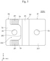
- Fig. 5 is a plan view of the busbar 2A.
- the battery module 100 of the present embodiment has the most distinctive feature in the structure of the busbar 2A.
- the busbar 2A is a connecting conductor electrically and mechanically connecting the cell terminal 1p of one of the adjacent battery cells 1 in the stacking direction of the battery cells and the cell terminal 1n of the other battery cell, and is also a dissimilar metal junction structure formed by joining a copper portion 2e containing copper and an aluminum portion 2f containing aluminum.
- the busbar 2A has a pair of connection face portions 2c1 and 2c2, and a bridge portion 2d joining this pair of connection face portions 2c1 and 2c2.
- connection face portion 2c1 to be joined to the cell terminal 1p is a flat rectangular portion formed only with the aluminum portion 2f, and is disposed on the top surface of the cell terminal 1p and joined by laser welding.
- laser is applied to the surface of the connection face portion 2c1 so as to move the laser along a positioning hole 2z of the connection face portion 2c1 (see Figs. 4 and 5 ) with the cell terminal 1p and circumferentially around the solid portion outside the positioning hole 2z to join the cell terminal 1p and the connection face portion 2c1.
- connection face portion 2c2 to be joined to the negative cell terminal 1n is a substantially flat rectangular portion where the copper portion 2e and the aluminum portion 2f are overlapped in the overlapping direction (z-axis direction) with the cell terminal 1n, and the copper portion 2e is joined to the cell terminal 1n by laser welding.
- the copper portion 2e defines a flat rectangular plate portion, and a pair of arms 2f1 projecting parallel to each other from a flat portion 2g as a rising portion are overlapped on the flat portion for joining.
- the connection face portion 2c2 is a dissimilar metal joining portion where the pair of arms 2f1 including the aluminum portions 2f are overlapped for joining on the flat rectangular portion including the copper portion 2e (on the opposite side of the cell terminal 1n), that is, on the flat portion.
- the pair of arms 2f1 is formed by cutting out a central portion in the transverse direction (y-axis direction) of the aluminum portion 2f, which projects from a bridge portion 2d toward the connection face portion 2c2, from the projecting end toward the bridge portion 2d.
- the pair of arms 2f1 defines a recess 2f2, which is a recessed portion of the flat plate and is recessed toward the bridge portion 2d, therebetween so as to expose the copper portion 2e including the positioning hole 2z.
- the aluminum portion 2f of the connection face portion 2c2 is a molded product of a rectangular flat plate that is recessed toward the bridge portion 2d.
- the aluminum portion 2f overlaps only on a part of both ends of the rectangular flat copper portion 2e in the transverse direction (y-axis direction) and on the end of the rectangular flat copper portion 2e close to the bridge portion 2d to expose the other portion of the copper portion 2e.
- the copper portion 2e of the connection face portion 2c2 therefore can be joined to the cell terminal 1n by laser welding.
- laser is applied to the surface of the copper portion 2e at the connection face portion 2c2 so as to move the laser along the positioning hole 2z of the copper portion 2e of the connection face portion 2c2 (see Figs. 4 and 5 ) with the cell terminal 1n and circumferentially around the solid portion outside the positioning hole 2z to join the cell terminal 1n and the copper portion 2e of the connection face portion 2c2.
- Ultrasonic joining is used for joining the copper portion 2e and the aluminum portion 2f at the connection face portion 2c2, that is, the flat portion of the copper portion 2e and the pair of arms 2f1 of the aluminum portion 2f.
- the overlapping portions with the aluminum portions 2f at both ends of the rectangular flat copper portion 2e in the transverse direction (y-axis direction) are the joints 2x by ultrasonic joining.
- a face of the copper portion 2e on the opposite side of the aluminum portion 2f is placed on an anvil, and a horn is applied to the surface of the aluminum portion 2f on the opposite side of the copper portion 2e so as to apply ultrasonic vibrations to the overlapping portion of the copper portion 2e and the aluminum portion 2f for joining of the copper portion 2e and the aluminum portion 2f.
- the surface of the copper portion 2e or the aluminum portion 2f or both surfaces, which are to be ultrasonically joined, may undergo the coating processing such as tin or nickel plating.
- this embodiment includes the joint 2x of the copper portion 2e and the aluminum portion 2f formed at the connection face portion 2c2.
- Such a joint 2x of the copper portion 2e and the aluminum portion 2f formed at the connection face portion 2c2 increases the rigidity of the joint 2x of the copper portion 2e and the aluminum portion 2f and so increases the natural frequency, because the cell terminal 1n is a strong member.
- the present embodiment therefore reduces stress acting on the joint 2x between the copper portion 2e and the aluminum portion 2f due to vibrations of the battery module 100 or the like, and so keeps the joint strength high at the joint 2x between the copper portion 2e and the aluminum portion 2f.
- the present embodiment therefore enhances the resistance of the battery module 100 against vibrations and the like, and provides a reliable battery module 100.
- the bridge portion 2d is an inverted U-shaped portion formed only with the aluminum portion 2f, and has a pair of flat portions 2g (they may be called rising portions) rising vertically or at a steep angle upward from the bridge portion 2d-side ends of the aluminum portions 2f that define the connection face portions 2c1 and 2c2, and a folded portion 2h (they may be called a connection portion) joining between the pair of flat portions 2g.
- the folded portion 2h is curved in an arch shape.
- the copper portion 2e defining the connection face portion 2c2 that is exposed from the aluminum portion 2f has an end portion of the rectangular flat copper portion 2e projecting in the direction opposite to the bridge portion 2d. This end portion serves a detection conductor to detect the voltage, and is provided as a voltage detection wire joint 2y where lead wiring (not shown) for voltage detection is joined by brazing or ultrasonic welding.
- the voltage detection wire joint 2y may be located at the aluminum portion 2f defining the connection face portion 2c1.
- a terminal for joining voltage detection wiring may extend out as the voltage detection wire joint 2y from the aluminum portion 2f defining the connection face portion 2c1 or the copper portion 2e defining the connection face portion 2c2, and lead wiring for voltage detection (not shown) may be joined to this extended terminal by brazing or ultrasonic welding.
- the extended terminal and the lead wiring may be connected with a terminal including an elastic member for connecting them under pressure.
- Fig. 6 is an enlarged perspective view of the battery module 100 in Fig. 1
- Fig. 7 is an enlarged cross-sectional view taken along the line VII-VII of Fig. 6
- Fig. 8 is a perspective view of the busbar 2B connected to the module terminal 101N in Fig. 6
- Fig. 9 is a perspective view of the busbar 2B connected to the module terminal 101P.
- Fig. 6 is a cutaway view of a terminal cover, which is a part of the module cover 25.
- This embodiment has a feature in that the busbar 2B connected to the module terminal 101N includes a fuse 2a, which is the smallest portion in volume in the current path, and has a space S below the fuse 2a of the busbar 2B for dropping the melted fuse 2a.
- the term “below” refers to vertically below when the battery module 100 is placed so that the supported face 20a of the housing 20 is horizontal.
- the fuse 2a may be disposed in the busbar 2B connected to the module terminal 101P.
- the busbar 2B1 has a pair of connection face portions 2c1 and 2c2 that are placed side by side in the x-axis direction, and a bridge portion 2d extending from these connection face portions in the y-axis direction so as to join this pair of connection face portions 2c1 and 2c2 outside of these connection face portions.
- connection face portions 2c1 and 2c2 are rectangular flat plates.
- the connection face portion 2c1 to be connected to the module terminal 101N and the connection face portion 2c2 to be connected to the cell terminal 1n are different in height in the z-axis direction.
- the connection face portion 2c1 is located higher than the connection face portion 2c2.
- the height of the connection face portion 2c1 and the connection face portion 2c2 may be the same, or their relationship in height may be reversed.
- the bridge portion 2d is a bent portion in the direction (y-axis direction) to intersect the connection face portions 2c1 and 2c2. More particularly, the bridge portion 2d includes a U-shaped first bridge portion 2d1, a U-shaped second bridge portion 2d2 placed lateral of the first bridge portion 2d1 in the x-axis direction, and the fuse 2a connecting between the two bridge portions in the x-axis direction.
- the first bridge portion 2d1 and the second bridge portion 2d2 are the same in height in the height direction (z-axis direction) of the battery cells 1.
- the first bridge portion 2d1 includes a pair of flat portions 2g1 horizontally placed in the z-axis direction and a folded portion 2h1 (this may be called a connection portion) joining the pair of flat portions 2g1.
- the folded portion 2h1 is curved in an arch shape.
- the flat portion 2g1 connected to the connection face portion 2c1 and the flat portion 2g1 connected to the fuse 2a face each other in the Z-axis direction, and they are connected by the folded portion 2h1 at their ends on the opposite side of the connection face portion 2c1.
- connection face portion 2c1 and connection surface portion 2c1-side end of the lower flat portion 2g1 in the z-axis direction of the pair of flat portions 2g1 are connected by a flat bridge 2w (this may be called a rising portion) extending (rising) in the z-axis direction.
- the second bridge portion 2d2 includes a pair of flat portions 2g2 horizontally placed in the z-axis direction and a folded portion 2h2 (this may be called a connection portion) joining the pair of flat portions 2g2.
- the folded portion 2h2 is curved in an arch shape.
- the flat portion 2g2 connected to the connection face portion 2c2 and the flat portion 2g2 connected to the fuse 2a face each other in the z-axis direction, and they are connected by the folded portion 2h2 at their ends on the opposite side of the connection face portion 2c2.
- the lower flat portion 2g2 in the z-axis direction has a connection face portion 2c2-side end connected to the bridge portion 2d-side end of the connection face portion 2c2 in such a manner that the connection face portion 2c2-side end extends horizontally in the y-axis direction toward the connection face portion 2c2.
- the fuse 2a-side end of the upper flat portion 2g1 in the z-axis direction of the pair of flat portions 2g1 and the fuse 2a-side end of the upper flat portion 2g2 in the z-axis direction of the pair of flat portions 2g2 are connected by the fuse 2a.
- the current path between the first bridge portion 2d1 and the second bridge portion 2d2 includes only the fuse 2a, which has a smaller current carrying area than those of the first bridge portion 2d1 and the second bridge portion 2d2, and is the smallest volume current path in the busbar 2B1.
- the busbar 2B1 is a dissimilar metal joint structure formed by joining the copper portion 2e containing copper and the aluminum portion 2f containing aluminum. Clad joining is used to join these dissimilar metals, and so the busbar 2B1 may be referred to as a clad busbar.
- the connection face portions 2c1 and 2c2 and the bridge portion 2w are the copper portions 2e, and the bridge portion 2d is the aluminum portion 2f.
- a part of the bridge portion 2d (e.g., the upper flat portion 2g1 in the z-axis direction of the pair of flat portions 2g1, the upper flat portion 2g2 in the z-axis direction of the pair of flat portions 2g2, and the fuse 2a) may be the aluminum portions 2f, and the remaining may be the copper portions 2e.
- This embodiment includes the folded parts 2h due to the space in the insulation cover 24 to store the busbar.
- the folded parts 2h may be omitted.
- the bridge portion 2w also can be omitted.
- the space S to allow the melted fuse 2a to fall is defined by the battery cell 1 and the housing 20.
- the space S below the fuse 2a is an internal space of the housing 20 defined by the cell terminal 1p or 1n and the cell case 1a of the battery cell 1 and the cell holder 21 of the housing 20.
- the space S faces the lower face of the busbar 2B1 opposed to the battery cell 1.
- the space S has a depth that is equal to or longer than the height of the cell terminal 1n in the direction (z-axis direction) perpendicular to the supported face 20a of the housing 20 and has a sufficiently large volume compared to the volume of the fuse 2a.
- the fuse 2a can be located farther from the cell terminal 1n. This prevents a melted metal material from forming a new current path between the positive cell terminal 1p and the negative cell terminal 1n of the battery cell 1 more reliably, and so further improves the safety of the battery module 100.
- the busbar 2B2 has a pair of connection face portions 2c1 and 2c2 that are placed side by side in the x-axis direction, and a bridge portion 2d joining this pair of connection face portions 2c1 and 2c2.
- connection face portions 2c1 and 2c2 are rectangular flat plates.
- the connection face portion 2c1 to be connected to the module terminal 101P and the connection face portion 2c2 to be connected to the cell terminal 1p are different in height in the z-axis direction.
- the connection face portion 2c1 is located higher than the connection face portion 2c2.
- the height of the connection face portion 2c1 and the connection face portion 2c2 may be the same, or their relationship in height may be reversed.
- the bridge portion 2d is a flat rectangular portion that is bent (rising) in the direction (z-axis direction) that intersects the connection face portions 2c1 and 2c2, and may be called a rising portion.
- the busbar 2B2 is a dissimilar metal joint structure formed by joining a copper portion 2e containing copper and an aluminum portion 2f containing aluminum. Clad joining is used to join these dissimilar metals, and so the busbar 2B2 may be referred to as a clad busbar.
- a part from the connection face portion 2c1 to a part of the bridge portion 2d is the copper portion 2e, and a part from the connection face portion 2c2 to the part of the bridge portion 2d is the aluminum portion 2f.
- Figs. 10 to 12 show Embodiment 2 of the present invention.
- this embodiment is for keeping a joint strength high at the joint 2x between the copper portion 2e and the aluminum portion 2f of the busbar 2A, and its structure is different from that of Embodiment 1.
- Fig. 10 is a perspective view of the busbar 2A
- Fig. 11 is a plan view of the busbar 2A
- Fig. 12 is a side view of the busbar 2A.
- the configuration of the battery module is the same as that of Embodiment 1 except for the busbar 2A, and the following describes differences from Embodiment 1 only.
- the busbar 2A is a connecting conductor electrically and mechanically connecting the cell terminal 1p of one of the adjacent battery cells 1 in the stacking direction of the battery cells and the cell terminal 1n of the other battery cell, and is also a dissimilar metal junction structure formed by joining a copper portion 2e containing copper and an aluminum portion 2f containing aluminum.
- the busbar 2A has a pair of connection face portions 2c1 and 2c2, and a bridge portion 2d joining this pair of connection face portions 2c1 and 2c2.
- connection face portion 2c1 to be joined to the cell terminal 1p is a flat rectangular portion formed only with the aluminum portion 2f, and is disposed on the top surface of the cell terminal 1p and joined by laser welding.
- laser is applied to the surface of the connection face portion 2c1 so as to move the laser along the positioning hole 2z of the connection face portion 2c1 (see Figs. 10 and 11 ) with the cell terminal 1p and circumferentially around the solid portion outside the positioning hole 2z to join the cell terminal 1p and the connection face portion 2c1.
- connection face portion 2c2 to be joined to the negative cell terminal 1n is a flat rectangular portion formed with the copper portion 2e only, and is disposed on the top surface of the cell terminal 1n and joined by laser welding.
- laser is applied to the surface of the connection face portion 2c2 so as to move the laser along the positioning hole 2z of the connection face portion 2c2 (see Figs. 10 and 11 ) with the cell terminal 1n and circumferentially around the solid portion outside the positioning hole 2z to join the cell terminal 1n and the connection face portion 2c2.
- the bridge portion 2d is an inverted U-shaped portion formed with the copper portion 2e and the aluminum portion 2f, and has a flat portion 2g (this may be called a rising portion) rising vertically or at a steep angle upward from the bridge portion 2d side-end of the aluminum portion 2f that defines the connection face portions 2c1, a flat portion 2v opposed to the flat portion 2g in the x-axis direction, and a folded portion 2h (this may be called a connection portion) joining between the flat portions 2g and 2v.
- a flat portion 2g this may be called a rising portion
- a folded portion 2h this may be called a connection portion
- the folded portion 2h is curved in an arch shape.
- the flat portion 2g and the folded portion 2h include the aluminum portions 2f, and the flat portion 2v includes the joining of the copper portion 2e and the aluminum portion 2f.
- the flat portion 2v is a dissimilar metal joining portion where the copper portion 2e and the aluminum portion 2f are overlapped for joining.
- the flat portion 2v in this embodiment corresponds to one of the rising portions described in the claims, and the flat portion 2g corresponds to the other rising portion described in the claims.
- the flat portion 2g has a shape having a cutout at the center of a rectangular flat plate in the y-axis direction, and includes two portions at both ends in the y-axis direction that extend upwardly in the z-axis direction from the bridge portion 2d-side end of the connection face portion 2c1.
- the folded portion 2h has a cutout at the center in the y-axis direction, and has both ends in the y-axis direction that extend toward the flat portion 2v. This exposes the inside of the bridge portion 2d, especially the inside of the central portion in the y-axis direction.
- the flat portion 2g and the folded portion 2h have the cutouts that expose a flat rectangular portion 2e1.
- the flat portion 2v is an overlapping portion of the flat rectangular portion 2e1 (first flat rectangular portion) rising vertically or at a steep angle upward from the bridge portion 2d side-end of the copper portion 2e of the connection face portion 2c2 and a flat rectangular portion 2f3 (second flat rectangular portion) extending downward in the z-axis direction from the folded portion 2h, where these flat rectangular portions are overlapped at their inner faces in the x-axis direction.
- this is the overlapping portion of the inner faces of the two members that are bent in a hook shape.
- the flat rectangular portion 2f3 is continuous to the folded portion 2h, and the side face opposed to the flat portion 2g is overlapped and joined to the connection face portion 2c2-side side face of the flat rectangular portion 2e1.
- the flat rectangular portion 2f3 extends over the upper end of the rising flat rectangular portion 2e1 and falls down there, so that they overlap in the x-axis direction.
- the busbar may have this configuration at the flat portion 2g.
- the flat rectangular portion of the copper portion 2e extends over the upper end of the flat rectangular portion of the aluminum portion 2f that rises upward from the aluminum portion, and falls down there, so that they overlap in the x-axis direction.
- the copper portion 2e and the aluminum portion 2f are joined by ultrasonic joining.
- the joint 2x between the copper portion 2e and the aluminum portion 2f is located at the center part in the y-axis direction of the overlapping portion between the flat rectangular portion 2e1 and the flat rectangular portion 2f3.
- Figs. 13 to 16 show Embodiment 3 of the present invention.
- this embodiment is for keeping a joint strength high at the joint 2x between the copper portion 2e and the aluminum portion 2f of the busbar 2A, and its structure is different from that of Embodiment 1.
- Fig. 13 is a perspective view of the busbar 2A
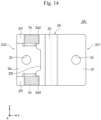
- Fig. 14 is a plan view of the busbar 2A
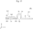
- Fig. 15 is a side view of the busbar 2A
- Fig. 16 is a perspective view of the busbar 2A placed on cell terminals.
- the configuration of the battery module is the same as that of Embodiment 1 except for the busbar 2A, and the following describes differences from Embodiment 1 only.
- the busbar 2A is a connecting conductor electrically and mechanically connecting the cell terminal 1p of one of the adjacent battery cells 1 in the stacking direction of the battery cells and the cell terminal 1n of the other battery cell, and is also a dissimilar metal junction structure formed by joining a copper portion 2e containing copper and an aluminum portion 2f containing aluminum.
- the busbar 2A has a pair of connection face portions 2c1 and 2c2, and a bridge portion 2d joining this pair of connection face portions 2c1 and 2c2.
- connection face portion 2c1 to be joined to the cell terminal 1p is a flat rectangular portion formed only with the aluminum portion 2f, and is disposed on the top surface of the cell terminal 1p and joined by laser welding.
- laser is applied to the surface of the connection face portion 2c1 so as to move the laser along the positioning hole 2z of the connection face portion 2c1 (see Figs. 13 and 14 ) with the cell terminal 1p and circumferentially around the solid portion outside the positioning hole 2z to join the cell terminal 1p and the connection face portion 2c1.
- connection face portion 2c2 to be joined to the negative cell terminal 1n is a substantially flat rectangular portion having a U-shaped part at each of the both ends in the longitudinal direction (x-axis direction) of the copper portion 2e so that the aluminum portion 2f is caught in the U-shaped parts of the copper portion 2e and is overlapped in the overlapping direction (z-axis direction) with the cell terminal 1n, and the copper portion 2e is joined to the cell terminal 1n by laser welding.
- the connection face portion 2c2 is a dissimilar metal joining portion where the flat recessed part of the aluminum portion 2f that is recessed toward the bridge portion 2d is overlapped on the flat rectangular portion of the copper portion 2e (on the opposite side of the cell terminal 1n).
- the aluminum portion 2f at the connection face portion 2c2 has a pair of arms 2f1.
- the pair of arms 2f1 is formed by cutting out a central portion of the aluminum portion 2f in the transverse direction (y-axis direction), which projects from a bridge portion 2d toward the connection face portion 2c2, from the projecting end toward the bridge portion 2d.
- the pair of arms 2f1 defines a recess 2f2, which is a recessed portion of the flat plate that is recessed toward the bridge portion 2d, therebetween so as to expose the copper portion 2e including the positioning hole 2z.
- the copper portion 2e of the connection face portion 2c2 has bases 2e3 and claws 2e2 facing each of the pair of arms 2f1 from one side and the other side of the overlapping direction.
- the bases 2e3 of the copper portion 2e are spaced apart from each other in the transverse direction and at both ends in the longitudinal direction to form pairs.
- the claws 2e2 of the copper portion 2e are formed by raising center parts in the transverse direction at both ends in the longitudinal direction to separate them from the cell terminal 1n located on one side in the overlapping direction relative to the bases 2e3, so that the arms 2f1 are insertable into gaps between the claws 2e2 and the bases 2e3.
- the aluminum portion 2f of the connection face portion 2c2 is a molded product of a rectangular flat plate that is recessed toward the bridge portion 2d.
- the aluminum portion 2f overlaps only on a part of both ends of the rectangular flat copper portion 2e in the transverse direction (y-axis direction) and on the end of the rectangular flat copper portion 2e close to the bridge portion 2d to expose the other portion of the copper portion 2e.
- the copper portion 2e of the connection face portion 2c2 therefore can be joined to the cell terminal 1n by laser welding.
- laser is applied to the surface of the copper portion 2e at the connection face portion 2c2 so as to move the laser along the positioning hole 2z of the copper portion 2e of the connection face portion 2c2 (see Figs. 13 and 14 ) with the cell terminal 1n and circumferentially around the solid portion outside the positioning hole 2z to join the cell terminal 1n and the copper portion 2e of the connection face portion 2c2.
- the copper portion 2e and the aluminum portion 2f (the pair of arms 2f1) at the connection face portion 2c2 are joined by ultrasonic joining.
- the overlapping portions with the aluminum portions 2f at the U-shaped flat portions located at both ends of the rectangular flat copper portion 2e in the transverse direction (y-axis direction), i.e., the overlapping portions of the arms 2f1 of the aluminum portion 2f with the claws 2e2 of the copper portion 2e are the joints 2x by ultrasonic joining.
- the face of the copper portion 2e opposed to the aluminum portion 2f is placed on an anvil, and a horn is applied to the surface of the aluminum portion 2f on the opposite side of the copper portion 2e so as to apply ultrasonic vibrations to the overlapping portion of the copper portion 2e and the aluminum portion 2f for joining of the copper portion 2e and the aluminum portion 2f.
- the surface of the copper portion 2e or the aluminum portion 2f or both surfaces, which are to be ultrasonically joined, may undergo the coating processing such as tin or nickel plating.
- this embodiment includes the copper portion 2e, a part of which has a U-shaped portion that sandwiches the aluminum portion 2e2 from above and below for overlapping, so as to form the joint 2x between the arms 2fl and the claws 2e2.
- the copper portion 2e is joined by laser to the cell terminal In, which is also made of copper, and they can be joined strongly because it is a copper-to-copper join. If external pressure is applied to the aluminum portion 2f in the upward direction, the joint becomes stronger, and if external pressure is applied to the aluminum portion 2f in the downward direction, the joint 2x does not bend downward because the cell terminal In under the aluminum portion 2f provides support.
- This embodiment therefore keeps a joint strength high at the joint 2x of the copper portion 2e and the aluminum portion 2f.
- the present embodiment therefore improves the resistance of the battery module against vibrations and the like, and provides a reliable battery module.
Landscapes
- Chemical & Material Sciences (AREA)
- Chemical Kinetics & Catalysis (AREA)
- Electrochemistry (AREA)
- General Chemical & Material Sciences (AREA)
- Engineering & Computer Science (AREA)
- Manufacturing & Machinery (AREA)
- Inorganic Chemistry (AREA)
- Connection Of Batteries Or Terminals (AREA)
- Battery Mounting, Suspending (AREA)
Description
- The present invention relates to battery modules each having a plurality of battery cells.
- A plurality of battery cells making up a battery module are joined to each other at their terminals via a connecting conductor called a busbar. The background art relating to this busbar includes a technique disclosed in Patent Literature 1. Patent Literature 1 describes a busbar including a copper part (701) that is laser welded to a negative electrode group and is made of a copper material, and an aluminum part (702) that is laser welded to a cell positive electrode group and is made of aluminum. This busbar is configured to linearly weld (705) these two parts made of two types of metals by an ultrasonic roller seam welding process (see paragraphs 0064, 0067 and
Fig. 15 ). - Patent Literature 1:
JP 2012-515418 A
Busbars with copper and aluminum portions which are joined to each other at their respective end faces, are disclosed inWO 2014/178114 A1 andWO 2019/069837 A1 . A single metal busbar allowing for a fusing part to be inserted into it, is disclosed inJP 2012 138239 A JP 2016 115458 A - A busbar joining the terminals of a plurality of batteries receives stress caused by vibrations applied to the battery module or a bulging of the battery cells during charging/discharging. A busbar including dissimilar metals joined as in Patent Literature 1 therefore has to be configured to keep a joint strength high so that the joint between the dissimilar metals does not peel off when stress acts on the joint between the dissimilar metals.
- One of the major aims of the present application is to keep a joint strength high at the joint between dissimilar metals of a busbar.
- The invention is defined in the appended claims. In order to solve the above problems, the present invention suggests the battery module defined in Claim 1. It includes: a plurality of battery cells each having terminals; and busbars each joining the terminals of the battery cells. Each busbar has: a plurality of connection face portions each connected to a corresponding one of the terminals to be joined; a plurality of rising portions each rising from a corresponding one of the plurality of connection face portions; and a connection portion connecting the plurality of rising portions. The busbar includes a copper portion containing copper and an aluminum portion containing aluminum. A joint between the copper portion and the aluminum portion is located on the connection face portion connected to the battery terminal. The connection face portion having the joint between the copper portion and the aluminum portion is connected to the battery cell terminal that is a strong member. This increases the rigidity at the joint between the copper portion and the aluminum portion and so increases the natural frequency, thus reducing stress acting on the joint between the copper portion and the aluminum portion. This configuration therefore keeps a joint strength high at the joint between the copper portion and the aluminum portion.
- As another aspect of the present invention to solve the above problems, the battery module defined in
Claim 5 is suggested. It includes a joint between the copper portion and the aluminum portion that is located on the rising portions rising from the connection face portions, and the copper portion and the aluminum portion are partially bent in a hook shape and are joined to each other at inner faces. In this way, a partial face of the copper portion and a partial face of the aluminum portion that define the rising portion are bent in a hook shape and are joined to each other at their inner faces, and this configuration allows the joint to receive a reactive force in the direction opposite to the stress acting on the joint between the copper portion and the aluminum portion. As a result, the stress acting on the joint between the copper portion and the aluminum portion is reduced. This configuration therefore keeps a joint strength high at the joint between the copper portion and the aluminum portion. - Major aspects of the present invention keep a joint strength high at the joint between dissimilar metals of the copper portion and the aluminum portion. This therefore enhances the resistance of the battery module against vibrations, and so provides a reliable battery module having excellent resistance.
- Further features of the present invention will be clear from the following descriptions and the attached drawings. Other problems, configurations and advantageous effects also will be clear from the following descriptions of the embodiments.
-
-
Fig. 1 is a perspective view showing the appearance of a battery module according to Embodiment 1 of the present invention. -
Fig. 2 is an exploded perspective view of the battery module inFig. 1 . -
Fig. 3 is an enlarged cross-sectional view of the major part of the battery module inFig. 1 . -
Fig. 4 is a perspective view of the busbar shown inFig. 3 . -
Fig. 5 is a plan view of the busbar shown inFig. 3 . -
Fig. 6 is an enlarged perspective view of a module terminal of the battery module inFig. 1 . -
Fig. 7 is an enlarged cross-sectional view of the module terminal taken along the line VII-VII ofFig. 6 . -
Fig. 8 is a perspective view of a busbar having a fuse that is connected to one of the module terminals that is shown inFig. 6 . -
Fig. 9 is a perspective view of a busbar that is connected to the other module terminal different from the module terminal shown inFig. 6 . -
Fig. 10 is a perspective view of a busbar connecting battery cells of a battery module according toEmbodiment 2 of the present invention. -
Fig. 11 is a plan view of the busbar shown inFig. 10 . -
Fig. 12 is a side view of the busbar shown inFig. 10 . -
Fig. 13 is a perspective view of a busbar connecting battery cells of a battery module according to Embodiment 3 of the present invention. -
Fig. 14 is a plan view of the busbar shown inFig. 13 . -
Fig. 15 is a side view of the busbar shown inFig. 13 . -
Fig. 16 is a perspective view of a busbar placed on cell terminals. -
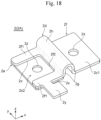
Fig. 17 is a perspective view of a busbar having a voltage detection wire joint disposed at a copper portion of the connection face portion. -
Fig. 18 is a perspective view of a busbar having a voltage detection wire joint disposed at an aluminum portion of the connection face portion. - The following describes some embodiments of the present invention, with reference to the attached drawings.
- The following may describe various parts of the battery module while referring to the orthogonal coordinate system having x axis, y axis, and z axis as shown in the drawings or the directional terms, such as upper, lower, left, right, front, and rear. These axes and directions are used for convenience in describing the illustrated state of the battery module, and do not limit the posture or arrangement of the battery module.
-
Figs. 1 to 9 show Embodiment 1 of the present invention. - First, the configuration of a
battery module 100 will be described referring toFigs. 1 and2 .Fig. 1 is a perspective view showing the appearance of thebattery module 100, andFig. 2 is an exploded perspective view of thebattery module 100. - The
battery module 100 mainly includes:module terminals battery cell group 10 including a plurality of battery cells 1; and busbars 2 electrically and mechanically connecting the plurality of battery cells 1 of thisbattery cell group 10 and electrically and mechanically connecting thisbattery cell group 10 with themodule terminals busbars 2 that electrically and mechanically connect the plurality of battery cells 1. Thebattery module 100 includes ahousing 20 and an electronic circuit board not shown in addition to the components described above. - The
battery cell group 10 is configured so that flattened rectangular battery cells 1, i.e., thin hexahedral or cuboid battery cells 1 having the thickness smaller than the width and the height, are stacked in the thickness direction (x-axis direction). Each battery cell 1 is a rectangular lithium-ion secondary battery, and includes a flattenedrectangular cell case 1a, an electrode group and electrolyte not shown that are stored in thiscell case 1a, and a pair ofcell terminals cell case 1a. Note here that thecell terminal 1p is a positive electrode terminal and thecell terminal 1n is a negative electrode terminal. - The
cell terminals cell case 1a. A resin insulating member is disposed between thecell terminal cell case 1a or between thecell case 1a and the electrode group for electrical insulation. The plurality of battery cells 1 making up thebattery cell group 10 are stacked while alternately reversing their direction by 180° so that thepositive cell terminal 1p of one of mutually adjacent battery cells 1 and thenegative cell terminal 1n of the other battery cell 1 are adjacent to each other in the stacking direction (x-axis direction). - The
housing 20 has a substantially cuboid shape, having the dimension in the length direction (x-axis direction) that is larger than the dimensions in the width direction (y-axis direction) and in the height direction (z-axis direction), and holds the plurality of battery cells 1 making up thebattery cell group 10. Specifically thehousing 20 has a plurality ofcell holders 21, a pair ofend plates 22, a pair ofside plates 23, aninsulation cover 24, and amodule cover 25. - In one example, the
cell holders 21 are made of a resin material such as polybutylene terephthalate (PBT). Eachcell holder 21 intervenes between mutually adjacent battery cells 1 of the plurality of battery cells 1 stacked in the thickness direction (x-axis direction), and holds these battery cells 1 to sandwich them from both sides in the thickness direction (x-axis direction). Themodule terminals battery module 100, are disposed at a pair ofcell holders 21 that are at both ends of thebattery cell group 10 in the stacking direction (x-axis direction) of the plurality of battery cells 1 making up thebattery cell group 10. Themodule terminal 101P is a positive electrode terminal and themodule terminal 101N is a negative electrode terminal. - The pair of
end plates 22 includes plate members made of metal. The pair ofend plates 22 is disposed at both ends of thebattery cell group 10 via the pair ofcell holders 21 disposed on both sides of thebattery cell group 10 in the stacking direction (x-axis direction) of the plurality of battery cells 1 making up thebattery cell group 10. Each of theend plates 22 as a pair has one face that is opposed to the plurality of battery cells 1 held at thecell holders 21. The other face of theend plate 22 is directed to the outside that is on the other side of thebattery cell group 10, and has a fixingpart 22a. - The fixing
part 22a at each of theend plates 22 as a pair is substantially cylindrical, and a part of the cylindrical face protrudes outward from the outer face of theend plate 22. Thecylindrical fixing part 22a has a bolt hole that is bored along the center axis parallel to the height direction (z-axis direction) of theend plate 22. This fixingpart 22a of theend plate 22 is to fix thebattery module 100 to an external mechanism such as a vehicle or another machine. The lower end face of this fixingpart 22a of theend plate 22 is a supportedface 20a of thehousing 20 that is supported by the external mechanism as stated above. - That is, to fix the
battery module 100 to the external mechanism, the operator may place the supportedface 20a of thehousing 20, which is the bottom face of each fixingpart 22a of theend plates 22, on the external mechanism for supporting, and insert a bolt into the bolt hole of the fixingpart 22a and screw the bolt together with an internal thread or a nut of the external mechanism for fastening. In other words, thebattery module 100 is fixed to the external mechanism with the bolt, and is supported by the external mechanism at the supported faces 20a of thehousing 20 that is the lower end faces of the fixingparts 22a of theend plates 22. - When the
battery module 100 is mounted on a vehicle such as an electric vehicle or a hybrid vehicle, the external mechanism to fix thebattery module 100 is the vehicle body of such a vehicle. Although not limited especially, when the vehicle to fix thebattery module 100 is placed on a horizontal road surface, the length direction (x-axis direction) and the width direction (y-axis direction) of thehousing 20 of thebattery module 100 are substantially parallel to the horizontal direction, and the height direction (z-axis direction) of thehousing 20 of thebattery module 100 is substantially parallel to the vertical direction. In this state, the supportedface 20a of thehousing 20 is substantially parallel to the horizontal plane. - The pair of
side plates 23 is disposed on both sides of the plurality of battery cells 1 making up thebattery cell group 10 in the width direction (y-axis direction) via thecell holders 21. Theside plates 23 as a pair are metal members each having a substantially rectangular shape, and are mutually opposed on both sides of thehousing 20 in the width direction (y-axis direction). Theside plates 23 as a pair are substantially oblongs, having the long-side direction, i.e., longitudinal direction in the stacking direction (x-axis direction) of the plurality of battery cells 1 making up thebattery cell group 10 and the short-side direction, i.e., transverse direction in the height direction (z-axis direction) of the plurality of battery cells 1 making up thebattery cell group 10. The pair ofside plates 23 are fastened at both ends in the longitudinal direction to the pair ofend plates 22 by fasteners such as rivets and bolts. The pair ofside plates 23 engage with recess-like grooves of thecell holders 21 at both ends in the transverse direction. - The
insulation cover 24 is a plate member made of resin such as PBT having an electrical insulating property. Theinsulation cover 24 is opposed to the upper end face of eachcell case 1a having thecell terminals insulation cover 24 has openings to expose the upper end faces of thecell terminals cell terminals adjacent busbars 2. The partition wall of theinsulation cover 24 is disposed so as to surround thecell terminals busbars 2. Various types of electric wiring are placed on theinsulation cover 24 to connect to thebattery cell group 10 and the electronic circuit board. - The electronic circuit board not shown is disposed between the
insulation cover 24 and themodule cover 25, i.e., on theinsulation cover 24 on the other side of thebattery cell group 10 in the height direction of thehousing 20, and electrically connects to thebusbars 2 via connecting conductors such as leading wiring and printed wiring and to a temperature sensor (thermistor) to detect the temperatures of the battery cells 1. - The
busbars 2 are connecting conductors that electrically and mechanically connect the plurality of battery cells 1 of thebattery cell group 10 and electrically and mechanically connect thebattery cell group 10 with themodule terminals - The
busbars 2 electrically and mechanically connecting the plurality of battery cells 1 of thebattery cell group 10 are a plurality ofbusbars 2A that electrically and mechanically connect the battery cells 1. Thesebusbars 2A are joined by welding to the upper end faces of thecell terminals battery cell group 10 that are exposed through the openings of theinsulation cover 24. Eachbusbar 2A electrically connects thecell terminal 1p of one of mutually adjacent battery cells 1 in the stacking direction and thecell terminal 1n of the other battery cell 1, so as to electrically connect all of the battery cells 1 of thebattery cell group 10 in series. - The
busbars 2 connecting thebattery cell group 10 with themodule terminals battery cell group 10 in the stacking direction of the battery cells. One of the busbars 2B as a pair electrically and mechanically connects to thecell terminal 1p of one of the pair of battery cells 1 disposed at both ends of the plurality of battery cells 1 in the stacking direction. The other busbar 2B electrically and mechanically connects to thecell terminal 1n of the other of the pair of battery cells 1 disposed at both ends of the plurality of battery cells 1 in the stacking direction. - One end of one of the busbars 2B as a pair is joined by welding to the upper end face of the
cell terminal 1p of one of the battery cells 1, and the other end is fastened to themodule terminal 101P disposed at one of the ends of thebattery cell group 10 in the stacking direction of the battery cells with a fastener such as a rivet or a bolt. One end of the other of the busbars 2B as a pair is joined by welding to the upper end face of thecell terminal 1n of one of the battery cells 1, and the other end is fastened to themodule terminal 101N disposed at the other end of thebattery cell group 10 in the stacking direction with a fastener such as a rivet or a bolt. - The
module cover 25 is a plate member made of resin such as PBT having an electrical insulating property. Themodule cover 25 is disposed at the upper end of thehousing 20 on the other side of thebattery cell group 10 in the height direction (z-axis direction) of thehousing 20 so as to cover theinsulation cover 24 and the electronic circuit board. Themodule cover 25 has terminal covers 25a at the positions corresponding to themodule terminals module terminals module cover 25 is fixed to the upper part of theinsulation cover 24 by engaginghooks 24b disposed at theframe 24a of theinsulation cover 24 with the side edge of themodule cover 25. - The
battery module 100 having the above-stated configuration has themodule terminals - Next the following describes the configuration of the
busbars 2 in details. - First, the configuration of the
busbars 2A will be described in details referring toFigs. 3 and5 .Fig. 3 is an enlarged cross-sectional view of thebattery module 100,Fig. 4 is a perspective view of thebusbar 2A, andFig. 5 is a plan view of thebusbar 2A. As described above, thebattery module 100 of the present embodiment has the most distinctive feature in the structure of thebusbar 2A. - As shown in
Fig. 3 , thebusbar 2A is a connecting conductor electrically and mechanically connecting thecell terminal 1p of one of the adjacent battery cells 1 in the stacking direction of the battery cells and thecell terminal 1n of the other battery cell, and is also a dissimilar metal junction structure formed by joining acopper portion 2e containing copper and analuminum portion 2f containing aluminum. - The
busbar 2A has a pair of connection face portions 2c1 and 2c2, and abridge portion 2d joining this pair of connection face portions 2c1 and 2c2. - Of the pair of connection face portions 2c1 and 2c2, the connection face portion 2c1 to be joined to the
cell terminal 1p is a flat rectangular portion formed only with thealuminum portion 2f, and is disposed on the top surface of thecell terminal 1p and joined by laser welding. For the laser welding, laser is applied to the surface of the connection face portion 2c1 so as to move the laser along apositioning hole 2z of the connection face portion 2c1 (seeFigs. 4 and5 ) with thecell terminal 1p and circumferentially around the solid portion outside thepositioning hole 2z to join thecell terminal 1p and the connection face portion 2c1. - The connection face portion 2c2 to be joined to the
negative cell terminal 1n is a substantially flat rectangular portion where thecopper portion 2e and thealuminum portion 2f are overlapped in the overlapping direction (z-axis direction) with thecell terminal 1n, and thecopper portion 2e is joined to thecell terminal 1n by laser welding. Thecopper portion 2e defines a flat rectangular plate portion, and a pair of arms 2f1 projecting parallel to each other from aflat portion 2g as a rising portion are overlapped on the flat portion for joining. The connection face portion 2c2 is a dissimilar metal joining portion where the pair of arms 2f1 including thealuminum portions 2f are overlapped for joining on the flat rectangular portion including thecopper portion 2e (on the opposite side of thecell terminal 1n), that is, on the flat portion. - The pair of arms 2f1 is formed by cutting out a central portion in the transverse direction (y-axis direction) of the
aluminum portion 2f, which projects from abridge portion 2d toward the connection face portion 2c2, from the projecting end toward thebridge portion 2d. The pair of arms 2f1 defines a recess 2f2, which is a recessed portion of the flat plate and is recessed toward thebridge portion 2d, therebetween so as to expose thecopper portion 2e including thepositioning hole 2z. - The
aluminum portion 2f of the connection face portion 2c2 is a molded product of a rectangular flat plate that is recessed toward thebridge portion 2d. Thealuminum portion 2f overlaps only on a part of both ends of the rectangularflat copper portion 2e in the transverse direction (y-axis direction) and on the end of the rectangularflat copper portion 2e close to thebridge portion 2d to expose the other portion of thecopper portion 2e. Thecopper portion 2e of the connection face portion 2c2 therefore can be joined to thecell terminal 1n by laser welding. For the laser welding, laser is applied to the surface of thecopper portion 2e at the connection face portion 2c2 so as to move the laser along thepositioning hole 2z of thecopper portion 2e of the connection face portion 2c2 (seeFigs. 4 and5 ) with thecell terminal 1n and circumferentially around the solid portion outside thepositioning hole 2z to join thecell terminal 1n and thecopper portion 2e of the connection face portion 2c2. - Ultrasonic joining is used for joining the
copper portion 2e and thealuminum portion 2f at the connection face portion 2c2, that is, the flat portion of thecopper portion 2e and the pair of arms 2f1 of thealuminum portion 2f. In this embodiment, the overlapping portions with thealuminum portions 2f at both ends of the rectangularflat copper portion 2e in the transverse direction (y-axis direction) are thejoints 2x by ultrasonic joining. For the ultrasonic joining, a face of thecopper portion 2e on the opposite side of thealuminum portion 2f is placed on an anvil, and a horn is applied to the surface of thealuminum portion 2f on the opposite side of thecopper portion 2e so as to apply ultrasonic vibrations to the overlapping portion of thecopper portion 2e and thealuminum portion 2f for joining of thecopper portion 2e and thealuminum portion 2f. The surface of thecopper portion 2e or thealuminum portion 2f or both surfaces, which are to be ultrasonically joined, may undergo the coating processing such as tin or nickel plating. - In this way, this embodiment includes the joint 2x of the
copper portion 2e and thealuminum portion 2f formed at the connection face portion 2c2. Such a joint 2x of thecopper portion 2e and thealuminum portion 2f formed at the connection face portion 2c2 increases the rigidity of the joint 2x of thecopper portion 2e and thealuminum portion 2f and so increases the natural frequency, because thecell terminal 1n is a strong member. The present embodiment therefore reduces stress acting on the joint 2x between thecopper portion 2e and thealuminum portion 2f due to vibrations of thebattery module 100 or the like, and so keeps the joint strength high at the joint 2x between thecopper portion 2e and thealuminum portion 2f. The present embodiment therefore enhances the resistance of thebattery module 100 against vibrations and the like, and provides areliable battery module 100. - The
bridge portion 2d is an inverted U-shaped portion formed only with thealuminum portion 2f, and has a pair offlat portions 2g (they may be called rising portions) rising vertically or at a steep angle upward from thebridge portion 2d-side ends of thealuminum portions 2f that define the connection face portions 2c1 and 2c2, and a foldedportion 2h (they may be called a connection portion) joining between the pair offlat portions 2g. The foldedportion 2h is curved in an arch shape. - The
copper portion 2e defining the connection face portion 2c2 that is exposed from thealuminum portion 2f has an end portion of the rectangularflat copper portion 2e projecting in the direction opposite to thebridge portion 2d. This end portion serves a detection conductor to detect the voltage, and is provided as a voltage detection wire joint 2y where lead wiring (not shown) for voltage detection is joined by brazing or ultrasonic welding. The voltage detection wire joint 2y may be located at thealuminum portion 2f defining the connection face portion 2c1. - In another example as shown in
Figs. 17 and18 , a terminal for joining voltage detection wiring may extend out as the voltage detection wire joint 2y from thealuminum portion 2f defining the connection face portion 2c1 or thecopper portion 2e defining the connection face portion 2c2, and lead wiring for voltage detection (not shown) may be joined to this extended terminal by brazing or ultrasonic welding. The extended terminal and the lead wiring may be connected with a terminal including an elastic member for connecting them under pressure. - Next, the configuration of the busbars 2B will be described in detail referring to
Figs. 6 to 9 .Fig. 6 is an enlarged perspective view of thebattery module 100 inFig. 1 ,Fig. 7 is an enlarged cross-sectional view taken along the line VII-VII ofFig. 6 ,Fig. 8 is a perspective view of the busbar 2B connected to themodule terminal 101N inFig. 6 , andFig. 9 is a perspective view of the busbar 2B connected to themodule terminal 101P.Fig. 6 is a cutaway view of a terminal cover, which is a part of themodule cover 25. This embodiment has a feature in that the busbar 2B connected to themodule terminal 101N includes afuse 2a, which is the smallest portion in volume in the current path, and has a space S below thefuse 2a of the busbar 2B for dropping the meltedfuse 2a. The term "below" refers to vertically below when thebattery module 100 is placed so that the supportedface 20a of thehousing 20 is horizontal. Thefuse 2a may be disposed in the busbar 2B connected to themodule terminal 101P. - First, the configuration of the busbar 2B1 connected to the
module terminal 101N is described in details with reference toFigs. 6 to 8 . - The busbar 2B1 has a pair of connection face portions 2c1 and 2c2 that are placed side by side in the x-axis direction, and a
bridge portion 2d extending from these connection face portions in the y-axis direction so as to join this pair of connection face portions 2c1 and 2c2 outside of these connection face portions. - The connection face portions 2c1 and 2c2 are rectangular flat plates. The connection face portion 2c1 to be connected to the
module terminal 101N and the connection face portion 2c2 to be connected to thecell terminal 1n are different in height in the z-axis direction. In the present embodiment, the connection face portion 2c1 is located higher than the connection face portion 2c2. The height of the connection face portion 2c1 and the connection face portion 2c2 may be the same, or their relationship in height may be reversed. - The
bridge portion 2d is a bent portion in the direction (y-axis direction) to intersect the connection face portions 2c1 and 2c2. More particularly, thebridge portion 2d includes a U-shaped first bridge portion 2d1, a U-shaped second bridge portion 2d2 placed lateral of the first bridge portion 2d1 in the x-axis direction, and thefuse 2a connecting between the two bridge portions in the x-axis direction. The first bridge portion 2d1 and the second bridge portion 2d2 are the same in height in the height direction (z-axis direction) of the battery cells 1. - The first bridge portion 2d1 includes a pair of flat portions 2g1 horizontally placed in the z-axis direction and a folded portion 2h1 (this may be called a connection portion) joining the pair of flat portions 2g1. The folded portion 2h1 is curved in an arch shape. The flat portion 2g1 connected to the connection face portion 2c1 and the flat portion 2g1 connected to the
fuse 2a face each other in the Z-axis direction, and they are connected by the folded portion 2h1 at their ends on the opposite side of the connection face portion 2c1. Thebridge 2d-side end of the connection face portion 2c1 and the connection surface portion 2c1-side end of the lower flat portion 2g1 in the z-axis direction of the pair of flat portions 2g1 are connected by aflat bridge 2w (this may be called a rising portion) extending (rising) in the z-axis direction. - The second bridge portion 2d2 includes a pair of flat portions 2g2 horizontally placed in the z-axis direction and a folded portion 2h2 (this may be called a connection portion) joining the pair of flat portions 2g2. The folded portion 2h2 is curved in an arch shape. The flat portion 2g2 connected to the connection face portion 2c2 and the flat portion 2g2 connected to the
fuse 2a face each other in the z-axis direction, and they are connected by the folded portion 2h2 at their ends on the opposite side of the connection face portion 2c2. Of the pair of flat portions 2g2, the lower flat portion 2g2 in the z-axis direction has a connection face portion 2c2-side end connected to thebridge portion 2d-side end of the connection face portion 2c2 in such a manner that the connection face portion 2c2-side end extends horizontally in the y-axis direction toward the connection face portion 2c2. - The
fuse 2a-side end of the upper flat portion 2g1 in the z-axis direction of the pair of flat portions 2g1 and thefuse 2a-side end of the upper flat portion 2g2 in the z-axis direction of the pair of flat portions 2g2 are connected by thefuse 2a. The current path between the first bridge portion 2d1 and the second bridge portion 2d2 includes only thefuse 2a, which has a smaller current carrying area than those of the first bridge portion 2d1 and the second bridge portion 2d2, and is the smallest volume current path in the busbar 2B1. With this configuration, when an excessive current flows through the busbar 2B1, the current density and temperature due to heat generation in thefuse 2a will be the highest in the busbar 2B1. When the temperature due to the heat generation exceeds the melting point temperature of the material of thefuse 2a, thefuse 2a blows the fastest in the busbar 2B1. This allows the current path of busbar 2B1 to be interrupted. - The busbar 2B1 is a dissimilar metal joint structure formed by joining the
copper portion 2e containing copper and thealuminum portion 2f containing aluminum. Clad joining is used to join these dissimilar metals, and so the busbar 2B1 may be referred to as a clad busbar. In this embodiment, the connection face portions 2c1 and 2c2 and thebridge portion 2w are thecopper portions 2e, and thebridge portion 2d is thealuminum portion 2f. A part of thebridge portion 2d (e.g., the upper flat portion 2g1 in the z-axis direction of the pair of flat portions 2g1, the upper flat portion 2g2 in the z-axis direction of the pair of flat portions 2g2, and thefuse 2a) may be thealuminum portions 2f, and the remaining may be thecopper portions 2e. - This embodiment includes the folded
parts 2h due to the space in theinsulation cover 24 to store the busbar. In another embodiment having a larger space to store the busbar, the foldedparts 2h may be omitted. - When the battery module is designed so that the
module terminal 101N and thecell terminal 1n are at the same height, thebridge portion 2w also can be omitted. - The space S to allow the melted
fuse 2a to fall is defined by the battery cell 1 and thehousing 20. Specifically the space S below thefuse 2a is an internal space of thehousing 20 defined by thecell terminal cell case 1a of the battery cell 1 and thecell holder 21 of thehousing 20. The space S faces the lower face of the busbar 2B1 opposed to the battery cell 1. The space S has a depth that is equal to or longer than the height of thecell terminal 1n in the direction (z-axis direction) perpendicular to the supportedface 20a of thehousing 20 and has a sufficiently large volume compared to the volume of thefuse 2a. If excessive current flows through the busbar 2B1 and the metal of thefuse 2a melts, the melted metal material of thefuse 2a falls down into the space S below thefuse 2a due to the action of gravity. This prevents the melted metal material from forming a new current path between thepositive cell terminal 1p and thenegative cell terminal 1n of the battery cell 1, thereby improving the safety of thebattery module 100. - With the configuration of the busbar 2B1 of this embodiment, the
fuse 2a can be located farther from thecell terminal 1n. This prevents a melted metal material from forming a new current path between thepositive cell terminal 1p and thenegative cell terminal 1n of the battery cell 1 more reliably, and so further improves the safety of thebattery module 100. - Next, the configuration of the busbar 2B2 connected to the
module terminal 101P will be described in detail referring toFig. 9 . - The busbar 2B2 has a pair of connection face portions 2c1 and 2c2 that are placed side by side in the x-axis direction, and a
bridge portion 2d joining this pair of connection face portions 2c1 and 2c2. - The connection face portions 2c1 and 2c2 are rectangular flat plates. The connection face portion 2c1 to be connected to the
module terminal 101P and the connection face portion 2c2 to be connected to thecell terminal 1p are different in height in the z-axis direction. In the present embodiment, the connection face portion 2c1 is located higher than the connection face portion 2c2. The height of the connection face portion 2c1 and the connection face portion 2c2 may be the same, or their relationship in height may be reversed. - The
bridge portion 2d is a flat rectangular portion that is bent (rising) in the direction (z-axis direction) that intersects the connection face portions 2c1 and 2c2, and may be called a rising portion. - The busbar 2B2 is a dissimilar metal joint structure formed by joining a
copper portion 2e containing copper and analuminum portion 2f containing aluminum. Clad joining is used to join these dissimilar metals, and so the busbar 2B2 may be referred to as a clad busbar. In this embodiment, a part from the connection face portion 2c1 to a part of thebridge portion 2d is thecopper portion 2e, and a part from the connection face portion 2c2 to the part of thebridge portion 2d is thealuminum portion 2f. -
Figs. 10 to 12 show Embodiment 2 of the present invention. - Similarly to Embodiment 1, this embodiment is for keeping a joint strength high at the joint 2x between the
copper portion 2e and thealuminum portion 2f of thebusbar 2A, and its structure is different from that of Embodiment 1.Fig. 10 is a perspective view of thebusbar 2A,Fig. 11 is a plan view of thebusbar 2A, andFig. 12 is a side view of thebusbar 2A. The configuration of the battery module is the same as that of Embodiment 1 except for thebusbar 2A, and the following describes differences from Embodiment 1 only. - The
busbar 2A is a connecting conductor electrically and mechanically connecting thecell terminal 1p of one of the adjacent battery cells 1 in the stacking direction of the battery cells and thecell terminal 1n of the other battery cell, and is also a dissimilar metal junction structure formed by joining acopper portion 2e containing copper and analuminum portion 2f containing aluminum. - As shown in
Fig. 10 , thebusbar 2A has a pair of connection face portions 2c1 and 2c2, and abridge portion 2d joining this pair of connection face portions 2c1 and 2c2. - Of the pair of connection face portions 2c1 and 2c2, the connection face portion 2c1 to be joined to the
cell terminal 1p is a flat rectangular portion formed only with thealuminum portion 2f, and is disposed on the top surface of thecell terminal 1p and joined by laser welding. For the laser welding, laser is applied to the surface of the connection face portion 2c1 so as to move the laser along thepositioning hole 2z of the connection face portion 2c1 (seeFigs. 10 and11 ) with thecell terminal 1p and circumferentially around the solid portion outside thepositioning hole 2z to join thecell terminal 1p and the connection face portion 2c1. - The connection face portion 2c2 to be joined to the
negative cell terminal 1n is a flat rectangular portion formed with thecopper portion 2e only, and is disposed on the top surface of thecell terminal 1n and joined by laser welding. For the laser welding, laser is applied to the surface of the connection face portion 2c2 so as to move the laser along thepositioning hole 2z of the connection face portion 2c2 (seeFigs. 10 and11 ) with thecell terminal 1n and circumferentially around the solid portion outside thepositioning hole 2z to join thecell terminal 1n and the connection face portion 2c2. - The
bridge portion 2d is an inverted U-shaped portion formed with thecopper portion 2e and thealuminum portion 2f, and has aflat portion 2g (this may be called a rising portion) rising vertically or at a steep angle upward from thebridge portion 2d side-end of thealuminum portion 2f that defines the connection face portions 2c1, aflat portion 2v opposed to theflat portion 2g in the x-axis direction, and a foldedportion 2h (this may be called a connection portion) joining between theflat portions - The folded
portion 2h is curved in an arch shape. Theflat portion 2g and the foldedportion 2h include thealuminum portions 2f, and theflat portion 2v includes the joining of thecopper portion 2e and thealuminum portion 2f. Theflat portion 2v is a dissimilar metal joining portion where thecopper portion 2e and thealuminum portion 2f are overlapped for joining. Theflat portion 2v in this embodiment corresponds to one of the rising portions described in the claims, and theflat portion 2g corresponds to the other rising portion described in the claims. - The
flat portion 2g has a shape having a cutout at the center of a rectangular flat plate in the y-axis direction, and includes two portions at both ends in the y-axis direction that extend upwardly in the z-axis direction from thebridge portion 2d-side end of the connection face portion 2c1. Similarly, the foldedportion 2h has a cutout at the center in the y-axis direction, and has both ends in the y-axis direction that extend toward theflat portion 2v. This exposes the inside of thebridge portion 2d, especially the inside of the central portion in the y-axis direction. In other words, theflat portion 2g and the foldedportion 2h have the cutouts that expose a flat rectangular portion 2e1. - The
flat portion 2v is an overlapping portion of the flat rectangular portion 2e1 (first flat rectangular portion) rising vertically or at a steep angle upward from thebridge portion 2d side-end of thecopper portion 2e of the connection face portion 2c2 and a flat rectangular portion 2f3 (second flat rectangular portion) extending downward in the z-axis direction from the foldedportion 2h, where these flat rectangular portions are overlapped at their inner faces in the x-axis direction. In other words, this is the overlapping portion of the inner faces of the two members that are bent in a hook shape. The flat rectangular portion 2f3 is continuous to the foldedportion 2h, and the side face opposed to theflat portion 2g is overlapped and joined to the connection face portion 2c2-side side face of the flat rectangular portion 2e1. - In this embodiment, the flat rectangular portion 2f3 extends over the upper end of the rising flat rectangular portion 2e1 and falls down there, so that they overlap in the x-axis direction. The busbar may have this configuration at the
flat portion 2g. In this case, the flat rectangular portion of thecopper portion 2e extends over the upper end of the flat rectangular portion of thealuminum portion 2f that rises upward from the aluminum portion, and falls down there, so that they overlap in the x-axis direction. - Similarly to Embodiment 1, the
copper portion 2e and thealuminum portion 2f are joined by ultrasonic joining. In this embodiment, the joint 2x between thecopper portion 2e and thealuminum portion 2f is located at the center part in the y-axis direction of the overlapping portion between the flat rectangular portion 2e1 and the flat rectangular portion 2f3. For the ultrasonic joining, an anvil is applied to one of the surfaces of the flat rectangular portion 2e1 on the opposite side of the flat rectangular portion 2f3 and the flat rectangular portion 2f3 on the opposite side of the flat rectangular portion 2e1 and at the center part in the y-axis direction, and a horn is applied to the surface of the other so as to apply ultrasonic vibrations to the overlapping portion of the flat rectangular portion 2e1 and the flat rectangular portion 2f3 for joining of thecopper portion 2e and thealuminum portion 2f. The surface of thecopper portion 2e or thealuminum portion 2f or both surfaces, which are to be ultrasonically joined, may undergo the coating processing such as tin or nickel plating. - In this way, this embodiment includes the joint 2x of the
copper portion 2e and thealuminum portion 2f formed at thebridge portion 2d. At thebridge portion 2d, the flat rectangular portion 2e1 and the flat rectangular portion 2f3 are bent into a hook shape and are boned at their opposed inner surfaces. If stress acts on the busbar in the direction of tearing off thecopper portion 2e and thealuminum portion 2f, this joining structure receives a pressurizing force to bring these portions into contact, and the elastic force at their bending portions acts on the joint 2x of thecopper portion 2e and thealuminum portion 2f as the reaction force in the direction opposite to the direction of the stress acting on the joint 2x of thecopper portion 2e and thealuminum portion 2f. As a result, the stress acting on the joint 2x between thecopper portion 2e and thealuminum portion 2f is reduced. - This means that if stress acts in the direction of separating the connection face portions 2c1 and 2c2 in the x-axis direction, a force will act on the busbar in a direction to bring the flat rectangular portion 2e1 of the
copper portion 2e and the flat rectangular portion 2f3 of thealuminum portion 2f into contact under pressure. This embodiment therefore keeps a joint strength high at the joint 2x of thecopper portion 2e and thealuminum portion 2f. Similarly to Embodiment 1, the present embodiment therefore improves the resistance of the battery module against vibrations and the like, and provides a reliable battery module. - A voltage detection wire joint may be disposed at either surface of the connection face portions 2c1 and 2c2. A terminal for connecting voltage detection wiring may extend out from either the connection face portion 2c1 or 2c2, and lead wiring for voltage detection (not shown) may be joined to this extended terminal by brazing or ultrasonic welding. The extended terminal and the lead wiring may be connected with a terminal including an elastic member for connecting them under pressure.
-
Figs. 13 to 16 show Embodiment 3 of the present invention. - Similarly to Embodiment 1, this embodiment is for keeping a joint strength high at the joint 2x between the
copper portion 2e and thealuminum portion 2f of thebusbar 2A, and its structure is different from that of Embodiment 1.Fig. 13 is a perspective view of thebusbar 2A,Fig. 14 is a plan view of thebusbar 2A,Fig. 15 is a side view of thebusbar 2A, andFig. 16 is a perspective view of thebusbar 2A placed on cell terminals. The configuration of the battery module is the same as that of Embodiment 1 except for thebusbar 2A, and the following describes differences from Embodiment 1 only. - As shown in
Fig. 16 , thebusbar 2A is a connecting conductor electrically and mechanically connecting thecell terminal 1p of one of the adjacent battery cells 1 in the stacking direction of the battery cells and thecell terminal 1n of the other battery cell, and is also a dissimilar metal junction structure formed by joining acopper portion 2e containing copper and analuminum portion 2f containing aluminum. - As shown in
Fig. 13 , thebusbar 2A has a pair of connection face portions 2c1 and 2c2, and abridge portion 2d joining this pair of connection face portions 2c1 and 2c2. - Of the pair of connection face portions 2c1 and 2c2, the connection face portion 2c1 to be joined to the
cell terminal 1p is a flat rectangular portion formed only with thealuminum portion 2f, and is disposed on the top surface of thecell terminal 1p and joined by laser welding. For the laser welding, laser is applied to the surface of the connection face portion 2c1 so as to move the laser along thepositioning hole 2z of the connection face portion 2c1 (seeFigs. 13 and14 ) with thecell terminal 1p and circumferentially around the solid portion outside thepositioning hole 2z to join thecell terminal 1p and the connection face portion 2c1. - The connection face portion 2c2 to be joined to the
negative cell terminal 1n is a substantially flat rectangular portion having a U-shaped part at each of the both ends in the longitudinal direction (x-axis direction) of thecopper portion 2e so that thealuminum portion 2f is caught in the U-shaped parts of thecopper portion 2e and is overlapped in the overlapping direction (z-axis direction) with thecell terminal 1n, and thecopper portion 2e is joined to thecell terminal 1n by laser welding. In other words, the connection face portion 2c2 is a dissimilar metal joining portion where the flat recessed part of thealuminum portion 2f that is recessed toward thebridge portion 2d is overlapped on the flat rectangular portion of thecopper portion 2e (on the opposite side of thecell terminal 1n). - The
aluminum portion 2f at the connection face portion 2c2 has a pair of arms 2f1. The pair of arms 2f1 is formed by cutting out a central portion of thealuminum portion 2f in the transverse direction (y-axis direction), which projects from abridge portion 2d toward the connection face portion 2c2, from the projecting end toward thebridge portion 2d. The pair of arms 2f1 defines a recess 2f2, which is a recessed portion of the flat plate that is recessed toward thebridge portion 2d, therebetween so as to expose thecopper portion 2e including thepositioning hole 2z. - The
copper portion 2e of the connection face portion 2c2 has bases 2e3 and claws 2e2 facing each of the pair of arms 2f1 from one side and the other side of the overlapping direction. The bases 2e3 of thecopper portion 2e are spaced apart from each other in the transverse direction and at both ends in the longitudinal direction to form pairs. The claws 2e2 of thecopper portion 2e are formed by raising center parts in the transverse direction at both ends in the longitudinal direction to separate them from thecell terminal 1n located on one side in the overlapping direction relative to the bases 2e3, so that the arms 2f1 are insertable into gaps between the claws 2e2 and the bases 2e3. - The
aluminum portion 2f of the connection face portion 2c2 is a molded product of a rectangular flat plate that is recessed toward thebridge portion 2d. Thealuminum portion 2f overlaps only on a part of both ends of the rectangularflat copper portion 2e in the transverse direction (y-axis direction) and on the end of the rectangularflat copper portion 2e close to thebridge portion 2d to expose the other portion of thecopper portion 2e. Thecopper portion 2e of the connection face portion 2c2 therefore can be joined to thecell terminal 1n by laser welding. For the laser welding, laser is applied to the surface of thecopper portion 2e at the connection face portion 2c2 so as to move the laser along thepositioning hole 2z of thecopper portion 2e of the connection face portion 2c2 (seeFigs. 13 and14 ) with thecell terminal 1n and circumferentially around the solid portion outside thepositioning hole 2z to join thecell terminal 1n and thecopper portion 2e of the connection face portion 2c2. - The
copper portion 2e and thealuminum portion 2f (the pair of arms 2f1) at the connection face portion 2c2 are joined by ultrasonic joining. In this embodiment, the overlapping portions with thealuminum portions 2f at the U-shaped flat portions located at both ends of the rectangularflat copper portion 2e in the transverse direction (y-axis direction), i.e., the overlapping portions of the arms 2f1 of thealuminum portion 2f with the claws 2e2 of thecopper portion 2e are thejoints 2x by ultrasonic joining. For the ultrasonic joining, the face of thecopper portion 2e opposed to thealuminum portion 2f is placed on an anvil, and a horn is applied to the surface of thealuminum portion 2f on the opposite side of thecopper portion 2e so as to apply ultrasonic vibrations to the overlapping portion of thecopper portion 2e and thealuminum portion 2f for joining of thecopper portion 2e and thealuminum portion 2f. The surface of thecopper portion 2e or thealuminum portion 2f or both surfaces, which are to be ultrasonically joined, may undergo the coating processing such as tin or nickel plating. - In this way, this embodiment includes the
copper portion 2e, a part of which has a U-shaped portion that sandwiches the aluminum portion 2e2 from above and below for overlapping, so as to form the joint 2x between the arms 2fl and the claws 2e2. Thecopper portion 2e is joined by laser to the cell terminal In, which is also made of copper, and they can be joined strongly because it is a copper-to-copper join. If external pressure is applied to thealuminum portion 2f in the upward direction, the joint becomes stronger, and if external pressure is applied to thealuminum portion 2f in the downward direction, the joint 2x does not bend downward because the cell terminal In under thealuminum portion 2f provides support. This embodiment therefore keeps a joint strength high at the joint 2x of thecopper portion 2e and thealuminum portion 2f. Similarly to Embodiment 1, the present embodiment therefore improves the resistance of the battery module against vibrations and the like, and provides a reliable battery module. - That is a detailed description of the embodiments of the present disclosure.
-
- 1
- Battery cell
- 1p
-
Cell terminal 1n Cell terminal - 2
- Busbar
- 2A
- Busbar
- 2B1(2B)
- Busbar
- 2B2(2B)
- Busbar
- 2a
- Fuse
- 2c1
- Connection face portion
- 2c2
- Connection face portion
- 2d
- Bridge portion
- 2d1
- First bridge portion
- 2d2
- Second bridge portion
- 2e
- Copper portion
- 2f
- Aluminum portion
- 2g
- Flat portion
- 2h
- Folded portion
- 2v
- Flat portion
- 2w
- Bridge portion
- 2x
- Joint
- 2y
- Voltage detection wire joint
- 2z
- Positioning hole
- 10
- Battery cell group
- 100
- Battery module
- 20
- Housing
- 20a
- Supported face
- 101P
- Module terminal
- 101N
- Module terminal
- S
- Space
Claims (7)
- A battery module comprising:a plurality of battery cells (1) each having terminals; andbusbars (2) each joining the terminals (1p, 1n) of the battery cells,each busbar having: a plurality of connection face portions (2c1, 2c2) each connected to a corresponding one of the terminals to be joined; a plurality of rising portions (2g) each rising from a corresponding one of the plurality of connection face portions; and a connection portion (2h) connecting the plurality of rising portions,the busbar comprising a copper portion (2e) including copper and an aluminum portion (2f) including aluminum,the copper portion and the aluminum portion being joined together,a joint (2x) between the copper portion and the aluminum portion being located on the connection face portions,the plurality of connection face portions having a pair of connection face portions disposed adjacently side by side on a plane,one of the connection face portions includes a dissimilar metal joining portion where the copper portion and the aluminum portion are overlapped for joining,the one of the connection face portions having:a flat portion including one of the copper portion and the aluminum portion, the flat portion being joined to one of the terminals of the battery cells; anda pair of arms (2f1) including the other of the copper portion and the aluminum portion, the arms projecting parallel to each other from one of the rising portions and being overlapped on the flat portion for joining.
- The battery module according to claim 1, wherein the flat portion has a positioning hole (2z) in a portion exposed between the pair of arms (2f1), the positioning hole being for laser-welding the flat portion to a corresponding terminal (1p, 1n) of the battery cells (1).
- The battery module according to claim 1, wherein the flat portion has bases and claws facing each of the arms (2f1) from one side and the other side of an overlapping direction of the flat portion and the arms, and
the joint (2x) is located at overlapping portions of the arms and the claws of the flat portion. - The battery module according to claim 1, wherein the one of the connection face portions (2c1, 2c2) has a detection conductor to detect voltage of the battery cells (1), and
the detection conductor is connected to a portion of the connection face portion that is different from the joint (2x) and a joint portion between the busbar (2) and the corresponding terminal (1p, 1n). - A battery module comprising:a plurality of battery cells (1) each having terminals (1p, 1n); andbusbars (2) each joining the terminals of the battery cells,each busbar having: a plurality of connection face portions (2c1, 2c2) each connected to a corresponding one of the terminals to be joined; a plurality of rising portions (2g) each rising from a corresponding one of the plurality of connection face portions; and a connection portion (2h) connecting the plurality of rising portions,the busbar comprising a copper portion (2e) including copper and an aluminum portion (2f) including aluminum,the copper portion and the aluminum portion being joined together,a joint (2x) between the copper portion and the aluminum portion being located on the rising portions,the copper portion and the aluminum portion being partially bent in a hook shape and being joined to each other at inner faces,the plurality of rising portions having a pair of rising portions that are opposed to each other,one of the rising portions including a dissimilar metal joining portion (2v) where the copper portion and the aluminum portion are overlapped for joining,the one of the rising portions having:a first flat rectangular portion (2e1) including one of the copper portion and the aluminum portion, the first flat rectangular portion being continuous to a corresponding one of the connection face portions; anda second flat rectangular portion (2f3) including the other of the copper portion and the aluminum portion, the second flat rectangular portion being continuous to the connection portion, the second flat rectangular portion having a side face opposed to the other rising portion, the side face being overlapped for joining to a side face of the first flat rectangular portion close to the corresponding connection face portion.
- The battery module according to claim 5, wherein the other rising portion (2g) and the connection portion (2h) each have a cutout to expose the first flat rectangular portion (2e1).
- The battery module according to any one of the preceding claims, wherein the joint (2x) is tin-plated or nickel-plated.
Applications Claiming Priority (2)
| Application Number | Priority Date | Filing Date | Title |
|---|---|---|---|
| JP2018205189 | 2018-10-31 | ||
| PCT/JP2019/040849 WO2020090492A1 (en) | 2018-10-31 | 2019-10-17 | Battery module |
Publications (3)
| Publication Number | Publication Date |
|---|---|
| EP3876305A1 EP3876305A1 (en) | 2021-09-08 |
| EP3876305A4 EP3876305A4 (en) | 2022-09-21 |
| EP3876305B1 true EP3876305B1 (en) | 2025-05-28 |
Family
ID=70463084
Family Applications (1)
| Application Number | Title | Priority Date | Filing Date |
|---|---|---|---|
| EP19879488.5A Active EP3876305B1 (en) | 2018-10-31 | 2019-10-17 | Battery module |
Country Status (5)
| Country | Link |
|---|---|
| US (2) | US12021266B2 (en) |
| EP (1) | EP3876305B1 (en) |
| JP (2) | JP7114731B2 (en) |
| CN (1) | CN112889180B (en) |
| WO (1) | WO2020090492A1 (en) |
Families Citing this family (15)
| Publication number | Priority date | Publication date | Assignee | Title |
|---|---|---|---|---|
| CN113519086B (en) * | 2019-03-12 | 2024-05-10 | 日本汽车能源株式会社 | Bus bar and battery module using same |
| KR102847235B1 (en) | 2020-06-17 | 2025-08-14 | 주식회사 엘지에너지솔루션 | Battery module with non-welded structure as a connection structure between a busbar and a voltage sensing member |
| CN117157820A (en) * | 2021-08-05 | 2023-12-01 | 日本汽车能源株式会社 | Battery pack |
| JP7600391B2 (en) * | 2021-08-26 | 2024-12-16 | エルジー エナジー ソリューション リミテッド | Battery pack with improved safety |
| CN116830380A (en) * | 2021-10-29 | 2023-09-29 | 宁德时代新能源科技股份有限公司 | Battery, electric equipment, manufacturing method and manufacturing equipment of battery |
| JP7444840B2 (en) * | 2021-11-17 | 2024-03-06 | プライムプラネットエナジー&ソリューションズ株式会社 | battery module |
| KR20230105965A (en) * | 2022-01-05 | 2023-07-12 | 삼성에스디아이 주식회사 | Battery pack |
| JP7488289B2 (en) | 2022-01-17 | 2024-05-21 | プライムプラネットエナジー&ソリューションズ株式会社 | Component joint structure, battery module, and battery pack |
| KR20230171100A (en) * | 2022-06-13 | 2023-12-20 | 주식회사 엘지에너지솔루션 | Secondary battery having improved terminal structure |
| CN218731641U (en) * | 2022-11-03 | 2023-03-24 | 湖北亿纬动力有限公司 | Bus bar, battery pack and electronic equipment |
| CN115890145A (en) * | 2022-11-15 | 2023-04-04 | 安庆帝伯格茨活塞环有限公司 | A preparation method of multi-layer busbar for new energy vehicle battery pack |
| JP7844396B2 (en) * | 2023-07-11 | 2026-04-13 | プライムプラネットエナジー&ソリューションズ株式会社 | Energy storage module |
| CN222813864U (en) * | 2023-12-15 | 2025-04-29 | 惠州亿纬锂能股份有限公司 | Connector bars, battery modules and battery packs |
| DE102023135807B4 (en) * | 2023-12-19 | 2025-11-20 | Andreas Stihl Ag & Co. Kg | Electric battery pack, process and electric battery system |
| EP4730545A1 (en) * | 2024-10-15 | 2026-04-22 | Samsung Sdi Co., Ltd. | Busbar and rechargeable battery module including the same |
Family Cites Families (22)
| Publication number | Priority date | Publication date | Assignee | Title |
|---|---|---|---|---|
| US5256502A (en) * | 1991-09-17 | 1993-10-26 | Gnb Incorporated | Modular, multicell lead-acid batteries |
| US8257848B2 (en) | 2009-01-12 | 2012-09-04 | A123 Systems, Inc. | Safety venting mechanism with tearing tooth structure for batteries |
| EP2441103B2 (en) | 2009-06-08 | 2018-09-12 | Auto-Kabel Management GmbH | Battery cell connector |
| JP5528746B2 (en) * | 2009-09-11 | 2014-06-25 | 三洋電機株式会社 | Assembled battery |
| JP5847377B2 (en) * | 2009-12-28 | 2016-01-20 | 三洋電機株式会社 | Power supply device and vehicle equipped with the same |
| JP2012138239A (en) | 2010-12-27 | 2012-07-19 | Panasonic Corp | Battery module |
| JPWO2012118014A1 (en) | 2011-02-28 | 2014-07-07 | 三洋電機株式会社 | Battery system and vehicle equipped with battery system |
| JP2013073929A (en) * | 2011-09-29 | 2013-04-22 | Gs Yuasa Corp | Battery pack |
| JP2013105567A (en) * | 2011-11-11 | 2013-05-30 | Hitachi Cable Ltd | Electrode lead connection body, nonaqueous electrolyte electricity storing device and method of manufacturing the same |
| US9318734B2 (en) | 2012-05-21 | 2016-04-19 | Tyco Electronics Corporation | Bimetal buss bar assembly |
| US9105912B2 (en) * | 2012-05-21 | 2015-08-11 | Tyco Electronics Corporation | Boltless battery cell connection |
| JP6078642B2 (en) | 2013-04-30 | 2017-02-08 | 日立オートモティブシステムズ株式会社 | Battery pack bus bar and battery pack |
| CN203932177U (en) * | 2013-09-30 | 2014-11-05 | 上海比亚迪有限公司 | A kind of cell connector and use the electrokinetic cell of this cell connector |
| JP6404045B2 (en) | 2014-09-09 | 2018-10-10 | 三井化学株式会社 | Lid, electric element, electric element unit, and method of manufacturing lid |
| JP6467211B2 (en) * | 2014-12-12 | 2019-02-06 | 日立オートモティブシステムズ株式会社 | Power storage module |
| JP6345101B2 (en) | 2014-12-17 | 2018-06-20 | 日立オートモティブシステムズ株式会社 | Power storage module |
| CN106159519B (en) * | 2015-03-26 | 2018-01-09 | 泰科电子(上海)有限公司 | Electric connector |
| CN107851767B (en) * | 2015-07-30 | 2020-10-30 | 三洋电机株式会社 | Power supply device and bus bar for battery unit |
| WO2018155090A1 (en) * | 2017-02-27 | 2018-08-30 | 日立オートモティブシステムズ株式会社 | Battery pack and busbar for battery pack |
| EP3461579B1 (en) | 2017-03-24 | 2021-10-13 | Hitachi Metals, Ltd. | Method for producing cladding material |
| CN118017170A (en) | 2017-10-05 | 2024-05-10 | 日本汽车能源株式会社 | Battery Module |
| CN113519086B (en) * | 2019-03-12 | 2024-05-10 | 日本汽车能源株式会社 | Bus bar and battery module using same |
-
2019
- 2019-10-17 JP JP2020553771A patent/JP7114731B2/en active Active
- 2019-10-17 US US17/287,029 patent/US12021266B2/en active Active
- 2019-10-17 CN CN201980067711.1A patent/CN112889180B/en active Active
- 2019-10-17 EP EP19879488.5A patent/EP3876305B1/en active Active
- 2019-10-17 WO PCT/JP2019/040849 patent/WO2020090492A1/en not_active Ceased
-
2022
- 2022-07-27 JP JP2022119261A patent/JP7324349B2/en active Active
-
2024
- 2024-05-10 US US18/660,664 patent/US20240291116A1/en active Pending
Also Published As
| Publication number | Publication date |
|---|---|
| WO2020090492A1 (en) | 2020-05-07 |
| JP2022159332A (en) | 2022-10-17 |
| US20240291116A1 (en) | 2024-08-29 |
| JP7324349B2 (en) | 2023-08-09 |
| JP7114731B2 (en) | 2022-08-08 |
| US12021266B2 (en) | 2024-06-25 |
| EP3876305A1 (en) | 2021-09-08 |
| CN112889180A (en) | 2021-06-01 |
| CN112889180B (en) | 2024-01-23 |
| JPWO2020090492A1 (en) | 2021-10-07 |
| US20210384592A1 (en) | 2021-12-09 |
| EP3876305A4 (en) | 2022-09-21 |
Similar Documents
| Publication | Publication Date | Title |
|---|---|---|
| EP3876305B1 (en) | Battery module | |
| US12283720B2 (en) | Bus bar, and battery module using same | |
| JP7307213B2 (en) | battery module | |
| CN111418090B (en) | Battery module, battery pack, device and method of manufacturing module bus bars | |
| CN111406329B (en) | Battery pack including connecting plate, electronic device and vehicle including battery pack | |
| EP3840085B1 (en) | Battery module | |
| CN110892552A (en) | Battery module with bus bar assembly | |
| CN210120177U (en) | Battery module, battery pack including the same, and vehicle including the battery pack | |
| KR20230031661A (en) | Battery module with improved wire bonding connection structure between busbar plate and ICB(Inter Connection Board) assembly and battery pack including the same | |
| CN115336098B (en) | Battery module, battery pack including the same, and vehicle | |
| WO2018043230A1 (en) | Connection module | |
| WO2020100621A1 (en) | Battery module | |
| JP2022074179A (en) | Voltage detection line and battery module | |
| CN111316464A (en) | Electrochemical battery cell pack, energy storage module and method of assembling the same | |
| JP6936397B2 (en) | Connection structure and battery module | |
| KR20240013593A (en) | Battery pack and electronic device including the same |
Legal Events
| Date | Code | Title | Description |
|---|---|---|---|
| STAA | Information on the status of an ep patent application or granted ep patent |
Free format text: STATUS: THE INTERNATIONAL PUBLICATION HAS BEEN MADE |
|
| PUAI | Public reference made under article 153(3) epc to a published international application that has entered the european phase |
Free format text: ORIGINAL CODE: 0009012 |
|
| STAA | Information on the status of an ep patent application or granted ep patent |
Free format text: STATUS: REQUEST FOR EXAMINATION WAS MADE |
|
| 17P | Request for examination filed |
Effective date: 20210415 |
|
| AK | Designated contracting states |
Kind code of ref document: A1 Designated state(s): AL AT BE BG CH CY CZ DE DK EE ES FI FR GB GR HR HU IE IS IT LI LT LU LV MC MK MT NL NO PL PT RO RS SE SI SK SM TR |
|
| DAV | Request for validation of the european patent (deleted) | ||
| DAX | Request for extension of the european patent (deleted) | ||
| REG | Reference to a national code |
Ref country code: DE Free format text: PREVIOUS MAIN CLASS: H01M0002200000 Ipc: H01M0050209000 Ref country code: DE Ref legal event code: R079 Ref document number: 602019070628 Country of ref document: DE Free format text: PREVIOUS MAIN CLASS: H01M0002200000 Ipc: H01M0050209000 |
|
| A4 | Supplementary search report drawn up and despatched |
Effective date: 20220823 |
|
| RIC1 | Information provided on ipc code assigned before grant |
Ipc: H01M 50/503 20210101ALI20220817BHEP Ipc: H01M 50/209 20210101AFI20220817BHEP |
|
| GRAP | Despatch of communication of intention to grant a patent |
Free format text: ORIGINAL CODE: EPIDOSNIGR1 |
|
| STAA | Information on the status of an ep patent application or granted ep patent |
Free format text: STATUS: GRANT OF PATENT IS INTENDED |
|
| INTG | Intention to grant announced |
Effective date: 20250220 |
|
| GRAS | Grant fee paid |
Free format text: ORIGINAL CODE: EPIDOSNIGR3 |
|
| GRAA | (expected) grant |
Free format text: ORIGINAL CODE: 0009210 |
|
| STAA | Information on the status of an ep patent application or granted ep patent |
Free format text: STATUS: THE PATENT HAS BEEN GRANTED |
|
| AK | Designated contracting states |
Kind code of ref document: B1 Designated state(s): AL AT BE BG CH CY CZ DE DK EE ES FI FR GB GR HR HU IE IS IT LI LT LU LV MC MK MT NL NO PL PT RO RS SE SI SK SM TR |
|
| REG | Reference to a national code |
Ref country code: GB Ref legal event code: FG4D |
|
| REG | Reference to a national code |
Ref country code: CH Ref legal event code: EP |
|
| REG | Reference to a national code |
Ref country code: IE Ref legal event code: FG4D Ref country code: DE Ref legal event code: R096 Ref document number: 602019070628 Country of ref document: DE |
|
| REG | Reference to a national code |
Ref country code: NL Ref legal event code: MP Effective date: 20250528 |
|
| PG25 | Lapsed in a contracting state [announced via postgrant information from national office to epo] |
Ref country code: FI Free format text: LAPSE BECAUSE OF FAILURE TO SUBMIT A TRANSLATION OF THE DESCRIPTION OR TO PAY THE FEE WITHIN THE PRESCRIBED TIME-LIMIT Effective date: 20250528 Ref country code: ES Free format text: LAPSE BECAUSE OF FAILURE TO SUBMIT A TRANSLATION OF THE DESCRIPTION OR TO PAY THE FEE WITHIN THE PRESCRIBED TIME-LIMIT Effective date: 20250528 |
|
| REG | Reference to a national code |
Ref country code: LT Ref legal event code: MG9D |
|
| PG25 | Lapsed in a contracting state [announced via postgrant information from national office to epo] |
Ref country code: NO Free format text: LAPSE BECAUSE OF FAILURE TO SUBMIT A TRANSLATION OF THE DESCRIPTION OR TO PAY THE FEE WITHIN THE PRESCRIBED TIME-LIMIT Effective date: 20250828 Ref country code: GR Free format text: LAPSE BECAUSE OF FAILURE TO SUBMIT A TRANSLATION OF THE DESCRIPTION OR TO PAY THE FEE WITHIN THE PRESCRIBED TIME-LIMIT Effective date: 20250829 |
|
| PG25 | Lapsed in a contracting state [announced via postgrant information from national office to epo] |
Ref country code: NL Free format text: LAPSE BECAUSE OF FAILURE TO SUBMIT A TRANSLATION OF THE DESCRIPTION OR TO PAY THE FEE WITHIN THE PRESCRIBED TIME-LIMIT Effective date: 20250528 Ref country code: PL Free format text: LAPSE BECAUSE OF FAILURE TO SUBMIT A TRANSLATION OF THE DESCRIPTION OR TO PAY THE FEE WITHIN THE PRESCRIBED TIME-LIMIT Effective date: 20250528 |
|
| PG25 | Lapsed in a contracting state [announced via postgrant information from national office to epo] |
Ref country code: BG Free format text: LAPSE BECAUSE OF FAILURE TO SUBMIT A TRANSLATION OF THE DESCRIPTION OR TO PAY THE FEE WITHIN THE PRESCRIBED TIME-LIMIT Effective date: 20250528 |
|
| PG25 | Lapsed in a contracting state [announced via postgrant information from national office to epo] |
Ref country code: HR Free format text: LAPSE BECAUSE OF FAILURE TO SUBMIT A TRANSLATION OF THE DESCRIPTION OR TO PAY THE FEE WITHIN THE PRESCRIBED TIME-LIMIT Effective date: 20250528 |
|
| PGFP | Annual fee paid to national office [announced via postgrant information from national office to epo] |
Ref country code: FR Payment date: 20250908 Year of fee payment: 7 |
|
| PG25 | Lapsed in a contracting state [announced via postgrant information from national office to epo] |
Ref country code: RS Free format text: LAPSE BECAUSE OF FAILURE TO SUBMIT A TRANSLATION OF THE DESCRIPTION OR TO PAY THE FEE WITHIN THE PRESCRIBED TIME-LIMIT Effective date: 20250828 |
|
| PG25 | Lapsed in a contracting state [announced via postgrant information from national office to epo] |
Ref country code: IS Free format text: LAPSE BECAUSE OF FAILURE TO SUBMIT A TRANSLATION OF THE DESCRIPTION OR TO PAY THE FEE WITHIN THE PRESCRIBED TIME-LIMIT Effective date: 20250928 |
|
| PG25 | Lapsed in a contracting state [announced via postgrant information from national office to epo] |
Ref country code: LV Free format text: LAPSE BECAUSE OF FAILURE TO SUBMIT A TRANSLATION OF THE DESCRIPTION OR TO PAY THE FEE WITHIN THE PRESCRIBED TIME-LIMIT Effective date: 20250528 |
|
| REG | Reference to a national code |
Ref country code: AT Ref legal event code: MK05 Ref document number: 1799193 Country of ref document: AT Kind code of ref document: T Effective date: 20250528 |
|
| PGFP | Annual fee paid to national office [announced via postgrant information from national office to epo] |
Ref country code: DE Payment date: 20250902 Year of fee payment: 7 |
|
| PG25 | Lapsed in a contracting state [announced via postgrant information from national office to epo] |
Ref country code: SM Free format text: LAPSE BECAUSE OF FAILURE TO SUBMIT A TRANSLATION OF THE DESCRIPTION OR TO PAY THE FEE WITHIN THE PRESCRIBED TIME-LIMIT Effective date: 20250528 Ref country code: AT Free format text: LAPSE BECAUSE OF FAILURE TO SUBMIT A TRANSLATION OF THE DESCRIPTION OR TO PAY THE FEE WITHIN THE PRESCRIBED TIME-LIMIT Effective date: 20250528 Ref country code: DK Free format text: LAPSE BECAUSE OF FAILURE TO SUBMIT A TRANSLATION OF THE DESCRIPTION OR TO PAY THE FEE WITHIN THE PRESCRIBED TIME-LIMIT Effective date: 20250528 |
|
| PG25 | Lapsed in a contracting state [announced via postgrant information from national office to epo] |
Ref country code: CZ Free format text: LAPSE BECAUSE OF FAILURE TO SUBMIT A TRANSLATION OF THE DESCRIPTION OR TO PAY THE FEE WITHIN THE PRESCRIBED TIME-LIMIT Effective date: 20250528 |
|
| PG25 | Lapsed in a contracting state [announced via postgrant information from national office to epo] |
Ref country code: EE Free format text: LAPSE BECAUSE OF FAILURE TO SUBMIT A TRANSLATION OF THE DESCRIPTION OR TO PAY THE FEE WITHIN THE PRESCRIBED TIME-LIMIT Effective date: 20250528 |
|
| PG25 | Lapsed in a contracting state [announced via postgrant information from national office to epo] |
Ref country code: RO Free format text: LAPSE BECAUSE OF FAILURE TO SUBMIT A TRANSLATION OF THE DESCRIPTION OR TO PAY THE FEE WITHIN THE PRESCRIBED TIME-LIMIT Effective date: 20250528 Ref country code: SK Free format text: LAPSE BECAUSE OF FAILURE TO SUBMIT A TRANSLATION OF THE DESCRIPTION OR TO PAY THE FEE WITHIN THE PRESCRIBED TIME-LIMIT Effective date: 20250528 |
|
| PG25 | Lapsed in a contracting state [announced via postgrant information from national office to epo] |
Ref country code: IT Free format text: LAPSE BECAUSE OF FAILURE TO SUBMIT A TRANSLATION OF THE DESCRIPTION OR TO PAY THE FEE WITHIN THE PRESCRIBED TIME-LIMIT Effective date: 20250528 |
|
| REG | Reference to a national code |
Ref country code: DE Ref legal event code: R097 Ref document number: 602019070628 Country of ref document: DE |
|
| PLBE | No opposition filed within time limit |
Free format text: ORIGINAL CODE: 0009261 |
|
| STAA | Information on the status of an ep patent application or granted ep patent |
Free format text: STATUS: NO OPPOSITION FILED WITHIN TIME LIMIT |
|
| REG | Reference to a national code |
Ref country code: CH Ref legal event code: L10 Free format text: ST27 STATUS EVENT CODE: U-0-0-L10-L00 (AS PROVIDED BY THE NATIONAL OFFICE) Effective date: 20260409 |