EP3876249A1 - Zero-sequence blocking transformer - Google Patents
Zero-sequence blocking transformer Download PDFInfo
- Publication number
- EP3876249A1 EP3876249A1 EP20161262.9A EP20161262A EP3876249A1 EP 3876249 A1 EP3876249 A1 EP 3876249A1 EP 20161262 A EP20161262 A EP 20161262A EP 3876249 A1 EP3876249 A1 EP 3876249A1
- Authority
- EP
- European Patent Office
- Prior art keywords
- zero
- core
- winding
- core part
- sequence blocking
- Prior art date
- Legal status (The legal status is an assumption and is not a legal conclusion. Google has not performed a legal analysis and makes no representation as to the accuracy of the status listed.)
- Pending
Links
Images


Classifications
-
- H—ELECTRICITY
- H01—ELECTRIC ELEMENTS
- H01F—MAGNETS; INDUCTANCES; TRANSFORMERS; SELECTION OF MATERIALS FOR THEIR MAGNETIC PROPERTIES
- H01F30/00—Fixed transformers not covered by group H01F19/00
- H01F30/02—Auto-transformers
-
- H—ELECTRICITY
- H01—ELECTRIC ELEMENTS
- H01F—MAGNETS; INDUCTANCES; TRANSFORMERS; SELECTION OF MATERIALS FOR THEIR MAGNETIC PROPERTIES
- H01F27/00—Details of transformers or inductances, in general
- H01F27/34—Special means for preventing or reducing unwanted electric or magnetic effects, e.g. no-load losses, reactive currents, harmonics, oscillations, leakage fields
- H01F27/346—Preventing or reducing leakage fields
-
- H—ELECTRICITY
- H01—ELECTRIC ELEMENTS
- H01F—MAGNETS; INDUCTANCES; TRANSFORMERS; SELECTION OF MATERIALS FOR THEIR MAGNETIC PROPERTIES
- H01F27/00—Details of transformers or inductances, in general
- H01F27/24—Magnetic cores
- H01F27/26—Fastening parts of the core together; Fastening or mounting the core on casing or support
-
- H—ELECTRICITY
- H01—ELECTRIC ELEMENTS
- H01F—MAGNETS; INDUCTANCES; TRANSFORMERS; SELECTION OF MATERIALS FOR THEIR MAGNETIC PROPERTIES
- H01F27/00—Details of transformers or inductances, in general
- H01F27/28—Coils; Windings; Conductive connections
-
- H—ELECTRICITY
- H01—ELECTRIC ELEMENTS
- H01F—MAGNETS; INDUCTANCES; TRANSFORMERS; SELECTION OF MATERIALS FOR THEIR MAGNETIC PROPERTIES
- H01F27/00—Details of transformers or inductances, in general
- H01F27/28—Coils; Windings; Conductive connections
- H01F27/30—Fastening or clamping coils, windings, or parts thereof together; Fastening or mounting coils or windings on core, casing, or other support
- H01F27/306—Fastening or mounting coils or windings on core, casing or other support
-
- H—ELECTRICITY
- H01—ELECTRIC ELEMENTS
- H01F—MAGNETS; INDUCTANCES; TRANSFORMERS; SELECTION OF MATERIALS FOR THEIR MAGNETIC PROPERTIES
- H01F3/00—Cores, Yokes, or armatures
- H01F3/10—Composite arrangements of magnetic circuits
- H01F3/12—Magnetic shunt paths
-
- H—ELECTRICITY
- H01—ELECTRIC ELEMENTS
- H01F—MAGNETS; INDUCTANCES; TRANSFORMERS; SELECTION OF MATERIALS FOR THEIR MAGNETIC PROPERTIES
- H01F3/00—Cores, Yokes, or armatures
- H01F3/10—Composite arrangements of magnetic circuits
- H01F3/14—Constrictions; Gaps, e.g. air-gaps
-
- H—ELECTRICITY
- H01—ELECTRIC ELEMENTS
- H01F—MAGNETS; INDUCTANCES; TRANSFORMERS; SELECTION OF MATERIALS FOR THEIR MAGNETIC PROPERTIES
- H01F30/00—Fixed transformers not covered by group H01F19/00
- H01F30/06—Fixed transformers not covered by group H01F19/00 characterised by the structure
- H01F30/12—Two-phase, three-phase or polyphase transformers
-
- H—ELECTRICITY
- H01—ELECTRIC ELEMENTS
- H01F—MAGNETS; INDUCTANCES; TRANSFORMERS; SELECTION OF MATERIALS FOR THEIR MAGNETIC PROPERTIES
- H01F30/00—Fixed transformers not covered by group H01F19/00
- H01F30/06—Fixed transformers not covered by group H01F19/00 characterised by the structure
- H01F30/16—Toroidal transformers
-
- H—ELECTRICITY
- H02—GENERATION; CONVERSION OR DISTRIBUTION OF ELECTRIC POWER
- H02M—APPARATUS FOR CONVERSION BETWEEN AC AND AC, BETWEEN AC AND DC, OR BETWEEN DC AND DC, AND FOR USE WITH MAINS OR SIMILAR POWER SUPPLY SYSTEMS; CONVERSION OF DC OR AC INPUT POWER INTO SURGE OUTPUT POWER; CONTROL OR REGULATION THEREOF
- H02M1/00—Details of apparatus for conversion
- H02M1/12—Arrangements for reducing harmonics from AC input or output
-
- H—ELECTRICITY
- H02—GENERATION; CONVERSION OR DISTRIBUTION OF ELECTRIC POWER
- H02M—APPARATUS FOR CONVERSION BETWEEN AC AND AC, BETWEEN AC AND DC, OR BETWEEN DC AND DC, AND FOR USE WITH MAINS OR SIMILAR POWER SUPPLY SYSTEMS; CONVERSION OF DC OR AC INPUT POWER INTO SURGE OUTPUT POWER; CONTROL OR REGULATION THEREOF
- H02M5/00—Conversion of AC power input into AC power output, e.g. for change of voltage, for change of frequency, for change of number of phases
- H02M5/02—Conversion of AC power input into AC power output, e.g. for change of voltage, for change of frequency, for change of number of phases without intermediate conversion into DC
- H02M5/04—Conversion of AC power input into AC power output, e.g. for change of voltage, for change of frequency, for change of number of phases without intermediate conversion into DC by static converters
- H02M5/10—Conversion of AC power input into AC power output, e.g. for change of voltage, for change of frequency, for change of number of phases without intermediate conversion into DC by static converters using transformers
-
- H—ELECTRICITY
- H02—GENERATION; CONVERSION OR DISTRIBUTION OF ELECTRIC POWER
- H02M—APPARATUS FOR CONVERSION BETWEEN AC AND AC, BETWEEN AC AND DC, OR BETWEEN DC AND DC, AND FOR USE WITH MAINS OR SIMILAR POWER SUPPLY SYSTEMS; CONVERSION OF DC OR AC INPUT POWER INTO SURGE OUTPUT POWER; CONTROL OR REGULATION THEREOF
- H02M7/00—Conversion of AC power input into DC power output; Conversion of DC power input into AC power output
- H02M7/02—Conversion of AC power input into DC power output without possibility of reversal
- H02M7/04—Conversion of AC power input into DC power output without possibility of reversal by static converters
- H02M7/06—Conversion of AC power input into DC power output without possibility of reversal by static converters using discharge tubes without control electrode or semiconductor devices without control electrode
- H02M7/068—Conversion of AC power input into DC power output without possibility of reversal by static converters using discharge tubes without control electrode or semiconductor devices without control electrode mounted on a transformer
-
- H—ELECTRICITY
- H02—GENERATION; CONVERSION OR DISTRIBUTION OF ELECTRIC POWER
- H02M—APPARATUS FOR CONVERSION BETWEEN AC AND AC, BETWEEN AC AND DC, OR BETWEEN DC AND DC, AND FOR USE WITH MAINS OR SIMILAR POWER SUPPLY SYSTEMS; CONVERSION OF DC OR AC INPUT POWER INTO SURGE OUTPUT POWER; CONTROL OR REGULATION THEREOF
- H02M7/00—Conversion of AC power input into DC power output; Conversion of DC power input into AC power output
- H02M7/02—Conversion of AC power input into DC power output without possibility of reversal
- H02M7/04—Conversion of AC power input into DC power output without possibility of reversal by static converters
- H02M7/06—Conversion of AC power input into DC power output without possibility of reversal by static converters using discharge tubes without control electrode or semiconductor devices without control electrode
- H02M7/08—Conversion of AC power input into DC power output without possibility of reversal by static converters using discharge tubes without control electrode or semiconductor devices without control electrode arranged for operation in parallel
-
- H—ELECTRICITY
- H02—GENERATION; CONVERSION OR DISTRIBUTION OF ELECTRIC POWER
- H02M—APPARATUS FOR CONVERSION BETWEEN AC AND AC, BETWEEN AC AND DC, OR BETWEEN DC AND DC, AND FOR USE WITH MAINS OR SIMILAR POWER SUPPLY SYSTEMS; CONVERSION OF DC OR AC INPUT POWER INTO SURGE OUTPUT POWER; CONTROL OR REGULATION THEREOF
- H02M1/00—Details of apparatus for conversion
- H02M1/0064—Magnetic structures combining different functions, e.g. storage, filtering or transformation
Definitions
- the present disclosure concerns designs for zero-sequence blocking transformers (ZSBTs).
- ZSBTs zero-sequence blocking transformers
- Zero-sequence blocking transformers are commonly used in multi-phase systems having several converters connected in parallel, such as auto-transformer rectifier units (ATRUs), to eliminate or block zero-sequence components in the output signals due to the parallel windings.
- Zero-sequence components are components that are at any one time equal in different phases of the system and thus give rise to undesirable harmonic content.
- ZSBTs are designed to present a high impedance between parallel outputs to block zero-sequence components, to remove triplen (3 rd , 6 th , 9 th etc) order harmonics.
- the ZSBT is commonly located in an ATRU between the diode bridge rectifiers and the common DC-link capacitor.
- a ZSBT present a leakage inductance which is a function of the leakage flux that does not flow from the primary to the secondary winding of the ZSBT. It is desirable to increase ZSBT leakage inductance as this improves the effect of reducing output current ripple from the diode bridge rectifier as well as improving overall ATRU input current power quality.
- each ZSBT therefore, will have a set leakage inductance, determined by its core geometry and winding arrangement.
- the present inventors have identified a need for a ZSBT design in which the leakage inductance can be controlled independently of the core geometry such that a given core can be easily adapted to have different leakage inductances for different needs.
- a zero-sequence blocking transformer comprising a first core part around which is wound a first winding and a second core part around which is wound a second winding, and a third core part to create an additional leakage flux path.
- the additional component part may be a rod of magnetic material fitted into the gap between the two windings to intentionally create an additional leakage flux path.
- an EE core geometry can be used and the additional leakage flux path is created by forming an air gap or adding a magnetic material insert in the leg which does not carry a winding.
- ATRUs are commonly used in medium to high power AC-DC power conversion systems used in e.g. aerospace applications.
- Figs. 1 and 2 show examples of 18-pulse and 24-pulse ATRUs. Other winding schemes and topologies are also known.
- ZSBTs are connected between the outputs of the diode bridge rectifiers and the DC-link capacitor.
- Fig. 1 shows an 18-pulse ATRU having a three-phase supply 1, an input filter 2, an 18-pulse ATU 3, a balancing resistor 4, three diode bridge rectifiers 5a, 5b and 5c, DC-link capacitor 8, load 7 and ZSBTs 6a, 6b, 6c between the rectifiers and the DC-link capacitor.
- Fig. 2 shows a 24-pulse ATRU having a three-phase supply 1, an input filter 2, a 24-pulse ATU 3, four diode bridge rectifiers 4a, 4b, 4c and 4d, DC-link capacitor 8, load 7 and ZSBTs 5a, 5b, 5c, 5d between the rectifiers and the DC-link capacitor.
- Fig. 3 shows a 12-pulse ATRU having a three-phase supply 1, an input filter 2, a 12-pulse ATU 3, two diode bridge rectifiers 4a, 4b, DC-link capacitor 8, load 7 and a 12-pulse ZSBT 5 between the rectifiers and the DC-link capacitor.
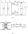
- ZSBTs are usually designed as a toroidal core 40 having two windings 20, 30 as shown in Fig. 4 .
- the main magnetic flux between the two windings 20,30 is usually equal and cancel each other out.
- ZSBTs have leakage inductances L leak and magnetizing inductances L mag as shown in the equivalent circuit in Fig. 4 . Only the leakage inductance is important in limiting zero-sequence currents between the outputs of the diode bridges as well as minimizing the output ripple currents.
- the leakage inductance is determined by the core geometry and cannot be controlled for different requirements.
- the ZSBT is designed such that the leakage inductance can be controlled independent of the coil geometry by addition of an extra leakage flux path between the windings. This can be applied to different types of core geometry.
- Fig. 5 shows an example of a toroidal core design according to the disclosure.
- an insert 50 of magnetic material is added in the space between the first and second windings 20,30. The effect of this is to create an extra leakage flux path which adds an additional leakage inductance L core as seen in the equivalent circuit of Fig. 5 .
- the overall leakage inductance of the ZSBT can be adjusted and controlled as required.
- an air-gap can be put between the magnetic insert and the toroidal core.
- a toroidal core design has two pairs of windings on opposing sides of the toroid.
- an insert 50' of magnetic material is provided in the space between the windings, which, again, provide an extra leakage flux path to add more leakage inductance.
- an air gap could also be incorporated to meet design requirements.
- Fig. 7 the concept is applied to an EE geometry core.
- Two options are shown in Fig. 7 .
- a first winding 20' is provided on a first leg 200 and a second winding 30' is provided on a second leg 300 and this geometry would determine the leakage inductance of the ZSBT.
- the third (middle) leg 400 which does not have a winding, is formed as an extra leakage flux path by the insertion of an additional leakage flux component 500 which may be an air gap or a magnetic insert or both.
- an additional leakage flux component 500 which may be an air gap or a magnetic insert or both.
- FIG. 7 shows an alternative modification of the EE core in which the left leg 200' and the middle leg 300' carry the first and second windings 20", 30" and the extra leakage flux path is formed on the other end leg 400' by the insertion of a leakage flux component 500' which may be an air gap or a magnetic insert.
- a leakage flux component 500' which may be an air gap or a magnetic insert.
- the core design of this disclosure allows the leakage inductance of ZSBTs to be designed in a controlled manner rather than being dependent on core geometry. Because the leakage inductance is mainly provided by the core part having no winding, the windings can have fewer turns and thus be smaller, resulting in a smaller overall core size which is lighter and uses less winding material.
Landscapes
- Engineering & Computer Science (AREA)
- Power Engineering (AREA)
- Chemical & Material Sciences (AREA)
- Composite Materials (AREA)
- Power Conversion In General (AREA)
Abstract
Description
- The present disclosure concerns designs for zero-sequence blocking transformers (ZSBTs).
- Zero-sequence blocking transformers (ZSBTs) are commonly used in multi-phase systems having several converters connected in parallel, such as auto-transformer rectifier units (ATRUs), to eliminate or block zero-sequence components in the output signals due to the parallel windings. Zero-sequence components are components that are at any one time equal in different phases of the system and thus give rise to undesirable harmonic content. ZSBTs are designed to present a high impedance between parallel outputs to block zero-sequence components, to remove triplen (3rd, 6th, 9th etc) order harmonics.
- The ZSBT is commonly located in an ATRU between the diode bridge rectifiers and the common DC-link capacitor.
- A ZSBT present a leakage inductance which is a function of the leakage flux that does not flow from the primary to the secondary winding of the ZSBT. It is desirable to increase ZSBT leakage inductance as this improves the effect of reducing output current ripple from the diode bridge rectifier as well as improving overall ATRU input current power quality.
- In conventional ZSBT designs, the magnetic core geometry and winding scheme are selected to provide a given leakage inductance. Each ZSBT, therefore, will have a set leakage inductance, determined by its core geometry and winding arrangement.
- The present inventors have identified a need for a ZSBT design in which the leakage inductance can be controlled independently of the core geometry such that a given core can be easily adapted to have different leakage inductances for different needs.
- According to the disclosure, there is provided a zero-sequence blocking transformer comprising a first core part around which is wound a first winding and a second core part around which is wound a second winding, and a third core part to create an additional leakage flux path.
- The concept of this disclosure can be applied to any known core structure by adding an additional leakage flux component part.
- In the case of a known toroidal core, the additional component part may be a rod of magnetic material fitted into the gap between the two windings to intentionally create an additional leakage flux path. Alternatively, an EE core geometry can be used and the additional leakage flux path is created by forming an air gap or adding a magnetic material insert in the leg which does not carry a winding.
-
-
Fig. 1 is a schematic circuit view of an 18-pulse ATRU with ZSBT. -
Fig. 2 . shows a 24-pulse ATRU with ZSBT. -
Fig. 3 shows a 12-pulse ATRU with ZSBT. -
Fig. 4 shows an example of a toroidal core used in a known ZSBT. -
Fig. 5 shows an example of a toroidal core modified according to this disclosure. -
Fig. 6 shows an example of a toroidal core for a 12-pulse ATRU such as shown in -
Fig. 3 , modified according to this disclosure -
Fig. 7 shows an example of an EE core modified according to this disclosure. - The described embodiments are by way of example only. The scope of this disclosure is limited only by the claims.
- The use of ZSBTs in ATRUs will be described for background, with reference to
Figs. 1, 2 and3 . - ATRUs are commonly used in medium to high power AC-DC power conversion systems used in e.g. aerospace applications.
Figs. 1 and 2 show examples of 18-pulse and 24-pulse ATRUs. Other winding schemes and topologies are also known. - As described above, to improve performance of the ATRU, ZSBTs are connected between the outputs of the diode bridge rectifiers and the DC-link capacitor.
-
Fig. 1 shows an 18-pulse ATRU having a three-phase supply 1, aninput filter 2, an 18-pulse ATU 3, abalancing resistor 4, threediode bridge rectifiers link capacitor 8,load 7 andZSBTs -
Fig. 2 shows a 24-pulse ATRU having a three-phase supply 1, aninput filter 2, a 24-pulse ATU 3, fourdiode bridge rectifiers link capacitor 8,load 7 andZSBTs -
Fig. 3 shows a 12-pulse ATRU having a three-phase supply 1, aninput filter 2, a 12-pulse ATU 3, twodiode bridge rectifiers link capacitor 8,load 7 and a 12-pulse ZSBT 5 between the rectifiers and the DC-link capacitor. - ZSBTs are usually designed as a
toroidal core 40 having twowindings Fig. 4 . The main magnetic flux between the twowindings Fig. 4 . Only the leakage inductance is important in limiting zero-sequence currents between the outputs of the diode bridges as well as minimizing the output ripple currents. - As mentioned above, in ZSBT designs as shown in
Fig. 3 , the leakage inductance is determined by the core geometry and cannot be controlled for different requirements. - According to the present disclosure, the ZSBT is designed such that the leakage inductance can be controlled independent of the coil geometry by addition of an extra leakage flux path between the windings. This can be applied to different types of core geometry.
-
Fig. 5 shows an example of a toroidal core design according to the disclosure. In this design, aninsert 50 of magnetic material is added in the space between the first andsecond windings Fig. 5 . By selecting the size and properties of themagnetic insert 50, the overall leakage inductance of the ZSBT can be adjusted and controlled as required. In case of being unable to find suitable size and properties of the magnetic insert, an air-gap can be put between the magnetic insert and the toroidal core. - In an alternative example, such as shown in
Fig. 6 , for use in e.g. a 12-pulse system such as shown inFig. 3 , a toroidal core design has two pairs of windings on opposing sides of the toroid. In a manner similar to that explained above forFig. 5 , an insert 50' of magnetic material is provided in the space between the windings, which, again, provide an extra leakage flux path to add more leakage inductance. Again, an air gap could also be incorporated to meet design requirements. - In an alternative example, shown in
Fig. 7 , the concept is applied to an EE geometry core. Two options are shown inFig. 7 . In the conventional EE transformer a first winding 20' is provided on afirst leg 200 and a second winding 30' is provided on asecond leg 300 and this geometry would determine the leakage inductance of the ZSBT. In the modification provided according to the present disclosure in the example to the left ofFig. 7 , the third (middle)leg 400, which does not have a winding, is formed as an extra leakage flux path by the insertion of an additionalleakage flux component 500 which may be an air gap or a magnetic insert or both. The right hand side ofFig. 7 shows an alternative modification of the EE core in which the left leg 200' and the middle leg 300' carry the first andsecond windings 20", 30" and the extra leakage flux path is formed on the other end leg 400' by the insertion of a leakage flux component 500' which may be an air gap or a magnetic insert. - Other core designs may be adapted similarly by insertion of an additional magnetic component without winding to create an additional leakage flux path.
- The core design of this disclosure allows the leakage inductance of ZSBTs to be designed in a controlled manner rather than being dependent on core geometry. Because the leakage inductance is mainly provided by the core part having no winding, the windings can have fewer turns and thus be smaller, resulting in a smaller overall core size which is lighter and uses less winding material.
Claims (10)
- A zero-sequence blocking transformer comprising a first core part around which is wound a first winding and a second core part around which is wound a second winding, and a third core part to create an additional leakage flux path.
- A zero-sequence blocking transformer as claimed in claim 1, where the third core part comprises an additional magnetic component without a winding.
- A zero-sequence blocking transformer as claimed in claim 1 or 2, wherein the first core part and the second core part combine to form a toroidal core defining a central space and wherein the third core part comprises a rod of magnetic material fitted into the central space between the two windings to create an additional leakage flux path.
- A zero-sequence blocking transformer as claimed in claim 3, wherein a third winding is wound about the first core part adjacent the first winding and a fourth winding is wound around the second core part adjacent the second winding.
- A zero-sequence blocking transformer as claimed in claim 3 or 4, wherein the third part also comprises an air gap.
- A zero-sequence blocking transformer as claimed in claim 1 or 2, wherein the first part and the second part are first and second legs of an EE core geometry and the third core part comprises a third leg of the EE core to which an air gap and/or a magnetic material is inserted.
- A zero-sequence blocking transformer according to claim 6, wherein the first and second legs are respective outer legs and the third leg is a middle leg between the first and second legs.
- A zero-sequence blocking transformer according to claim 6, wherein the first and third legs are respective outer legs and the second leg is a middle leg.
- A zero-sequence blocking transformer as claimed in claim 6, wherein the second and third legs are respective outer legs and the first leg is a middle leg.
- A multi-phase auto-transformer rectifier unit having a plurality of diode bridge rectifiers connected in parallel and a DC-link capacitor between the rectifiers and a load, and comprising a zero-sequence blocking transformer as claimed in any preceding claim between the rectifiers and the DC-link capacitor.
Priority Applications (2)
| Application Number | Priority Date | Filing Date | Title |
|---|---|---|---|
| EP20161262.9A EP3876249A1 (en) | 2020-03-05 | 2020-03-05 | Zero-sequence blocking transformer |
| US17/189,490 US20210280367A1 (en) | 2020-03-05 | 2021-03-02 | Zero-sequence blocking transformer |
Applications Claiming Priority (1)
| Application Number | Priority Date | Filing Date | Title |
|---|---|---|---|
| EP20161262.9A EP3876249A1 (en) | 2020-03-05 | 2020-03-05 | Zero-sequence blocking transformer |
Publications (1)
| Publication Number | Publication Date |
|---|---|
| EP3876249A1 true EP3876249A1 (en) | 2021-09-08 |
Family
ID=69779868
Family Applications (1)
| Application Number | Title | Priority Date | Filing Date |
|---|---|---|---|
| EP20161262.9A Pending EP3876249A1 (en) | 2020-03-05 | 2020-03-05 | Zero-sequence blocking transformer |
Country Status (2)
| Country | Link |
|---|---|
| US (1) | US20210280367A1 (en) |
| EP (1) | EP3876249A1 (en) |
Cited By (2)
| Publication number | Priority date | Publication date | Assignee | Title |
|---|---|---|---|---|
| EP4148968A1 (en) | 2021-09-14 | 2023-03-15 | Hamilton Sundstrand Corporation | Zero-sequence blocking transformer |
| US20240379275A1 (en) * | 2023-05-08 | 2024-11-14 | Archer Aviation Inc. | Systems and methods for enhancing leakage inductance of power transformers |
Families Citing this family (1)
| Publication number | Priority date | Publication date | Assignee | Title |
|---|---|---|---|---|
| CN114915173B (en) * | 2021-02-08 | 2026-04-21 | 台达电子工业股份有限公司 | Flexible power converter |
Citations (5)
| Publication number | Priority date | Publication date | Assignee | Title |
|---|---|---|---|---|
| US3387203A (en) * | 1965-01-07 | 1968-06-04 | Bell Telephone Labor Inc | Frequency changer |
| US6642672B2 (en) * | 2001-06-08 | 2003-11-04 | Delta Electronics, Inc. | Integrated filter with common-mode and differential-mode functions |
| US9054599B2 (en) * | 2012-03-15 | 2015-06-09 | Rockwell Automation Technologies, Inc. | Power converter and integrated DC choke therefor |
| CN106158250A (en) * | 2016-09-18 | 2016-11-23 | 田村(中国)企业管理有限公司 | A kind of ring-shaped inductors |
| DE102017214857A1 (en) * | 2017-08-24 | 2019-02-28 | Vacuumschmelze Gmbh & Co. Kg | Toroidal assembly, current-compensated inductor, and method of making a toroidal assembly |
Family Cites Families (4)
| Publication number | Priority date | Publication date | Assignee | Title |
|---|---|---|---|---|
| JP3580061B2 (en) * | 1996-12-27 | 2004-10-20 | 株式会社村田製作所 | choke coil |
| WO2002033711A1 (en) * | 2000-10-18 | 2002-04-25 | Koninklijke Philips Electronics N.V. | Inductor arrangement |
| NZ601844A (en) * | 2010-02-16 | 2013-04-26 | Ensitech Ip Pty Ltd | Constant-power supply for low impedance loads including a transformer with primary and secondary windings and a magnetic shunt for diverting magnetic flux associated with the windings |
| DE102010050828A1 (en) * | 2010-09-07 | 2012-03-08 | SUMIDA Components & Modules GmbH | Current-compensated choke with increased stray inductance |
-
2020
- 2020-03-05 EP EP20161262.9A patent/EP3876249A1/en active Pending
-
2021
- 2021-03-02 US US17/189,490 patent/US20210280367A1/en not_active Abandoned
Patent Citations (5)
| Publication number | Priority date | Publication date | Assignee | Title |
|---|---|---|---|---|
| US3387203A (en) * | 1965-01-07 | 1968-06-04 | Bell Telephone Labor Inc | Frequency changer |
| US6642672B2 (en) * | 2001-06-08 | 2003-11-04 | Delta Electronics, Inc. | Integrated filter with common-mode and differential-mode functions |
| US9054599B2 (en) * | 2012-03-15 | 2015-06-09 | Rockwell Automation Technologies, Inc. | Power converter and integrated DC choke therefor |
| CN106158250A (en) * | 2016-09-18 | 2016-11-23 | 田村(中国)企业管理有限公司 | A kind of ring-shaped inductors |
| DE102017214857A1 (en) * | 2017-08-24 | 2019-02-28 | Vacuumschmelze Gmbh & Co. Kg | Toroidal assembly, current-compensated inductor, and method of making a toroidal assembly |
Non-Patent Citations (2)
| Title |
|---|
| AITOR LAKA ET AL: "Novel Zero-Sequence Blocking Transformer (ZSBT) Using Three Single-Phase Transformers", IEEE TRANSACTIONS ON ENERGY CONVERSION, IEEE SERVICE CENTER, PISCATAWAY, NJ, US, vol. 28, no. 1, 1 March 2013 (2013-03-01), pages 234 - 242, XP011493442, ISSN: 0885-8969, DOI: 10.1109/TEC.2012.2229282 * |
| YAO WENLI ET AL: "Zero sequence blocking transformers for multi-pulse rectifier in aerospace applications", 2014 IEEE ENERGY CONVERSION CONGRESS AND EXPOSITION (ECCE), IEEE, 14 September 2014 (2014-09-14), pages 999 - 1006, XP032681173, DOI: 10.1109/ECCE.2014.6953508 * |
Cited By (4)
| Publication number | Priority date | Publication date | Assignee | Title |
|---|---|---|---|---|
| EP4148968A1 (en) | 2021-09-14 | 2023-03-15 | Hamilton Sundstrand Corporation | Zero-sequence blocking transformer |
| US12381032B2 (en) | 2021-09-14 | 2025-08-05 | Hamilton Sundstrand Corporation | Zero-sequence blocking transformer |
| US20240379275A1 (en) * | 2023-05-08 | 2024-11-14 | Archer Aviation Inc. | Systems and methods for enhancing leakage inductance of power transformers |
| WO2024233559A1 (en) * | 2023-05-08 | 2024-11-14 | Archer Aviation Inc. | Systems and methods for enhancing leakage inductance of power transformers |
Also Published As
| Publication number | Publication date |
|---|---|
| US20210280367A1 (en) | 2021-09-09 |
Similar Documents
| Publication | Publication Date | Title |
|---|---|---|
| US10971290B2 (en) | Magnetic assembly and power supply system with same | |
| US10389258B2 (en) | Integrated magnetic component and power converter | |
| US6101113A (en) | Transformers for multipulse AC/DC converters | |
| US8031042B2 (en) | Power converter magnetic devices | |
| US5481238A (en) | Compound inductors for use in switching regulators | |
| US7136293B2 (en) | Full wave series resonant type DC to DC power converter with integrated magnetics | |
| US5747981A (en) | Inductor for an electrical system | |
| US5905642A (en) | Apparatus and method to reduce common mode voltage from current source drives | |
| US7609536B2 (en) | Autotransformer AC/DC converter | |
| US9419538B2 (en) | AC/DC power conversion system and method of manufacture of same | |
| US20210280367A1 (en) | Zero-sequence blocking transformer | |
| US20060056207A1 (en) | Electromagnetic interference filter for an autotransformer | |
| US7265650B2 (en) | Power factor correction rectifier having independent inductive components | |
| US11948722B2 (en) | Planar winding transformer | |
| US10790697B2 (en) | System for converting electrical energy supplied by a network and a conversion method implemented by means of such a conversion system | |
| JP7295914B2 (en) | Three-phase magnetic assembly with integral core body | |
| US7161458B2 (en) | Electromagnetic device having independent inductive components | |
| JP2008178180A (en) | Rectifier circuit | |
| US12381032B2 (en) | Zero-sequence blocking transformer | |
| US6100781A (en) | High leakage inductance transformer | |
| US20240177926A1 (en) | Transformer assembly and electric conversion device | |
| CN110610795A (en) | Three-phase transformer for two-phase rectifier | |
| US10186370B1 (en) | Transformers with integrated inductors | |
| KR102910534B1 (en) | Transformer with split primary windings in parallel | |
| CN117501599B (en) | Flyback converter with improved magnetic configuration |
Legal Events
| Date | Code | Title | Description |
|---|---|---|---|
| PUAI | Public reference made under article 153(3) epc to a published international application that has entered the european phase |
Free format text: ORIGINAL CODE: 0009012 |
|
| STAA | Information on the status of an ep patent application or granted ep patent |
Free format text: STATUS: THE APPLICATION HAS BEEN PUBLISHED |
|
| AK | Designated contracting states |
Kind code of ref document: A1 Designated state(s): AL AT BE BG CH CY CZ DE DK EE ES FI FR GB GR HR HU IE IS IT LI LT LU LV MC MK MT NL NO PL PT RO RS SE SI SK SM TR |
|
| STAA | Information on the status of an ep patent application or granted ep patent |
Free format text: STATUS: REQUEST FOR EXAMINATION WAS MADE |
|
| 17P | Request for examination filed |
Effective date: 20220308 |
|
| RBV | Designated contracting states (corrected) |
Designated state(s): AL AT BE BG CH CY CZ DE DK EE ES FI FR GB GR HR HU IE IS IT LI LT LU LV MC MK MT NL NO PL PT RO RS SE SI SK SM TR |
|
| STAA | Information on the status of an ep patent application or granted ep patent |
Free format text: STATUS: EXAMINATION IS IN PROGRESS |
|
| 17Q | First examination report despatched |
Effective date: 20231130 |