EP3876074A1 - Dynamic configuration of a virtual keyboard - Google Patents
Dynamic configuration of a virtual keyboard Download PDFInfo
- Publication number
- EP3876074A1 EP3876074A1 EP20214422.6A EP20214422A EP3876074A1 EP 3876074 A1 EP3876074 A1 EP 3876074A1 EP 20214422 A EP20214422 A EP 20214422A EP 3876074 A1 EP3876074 A1 EP 3876074A1
- Authority
- EP
- European Patent Office
- Prior art keywords
- virtual keyboard
- string
- processor
- user
- keys
- Prior art date
- Legal status (The legal status is an assumption and is not a legal conclusion. Google has not performed a legal analysis and makes no representation as to the accuracy of the status listed.)
- Granted
Links
Images


Classifications
-
- G—PHYSICS
- G06—COMPUTING OR CALCULATING; COUNTING
- G06F—ELECTRIC DIGITAL DATA PROCESSING
- G06F3/00—Input arrangements for transferring data to be processed into a form capable of being handled by the computer; Output arrangements for transferring data from processing unit to output unit, e.g. interface arrangements
- G06F3/01—Input arrangements or combined input and output arrangements for interaction between user and computer
- G06F3/048—Interaction techniques based on graphical user interfaces [GUI]
- G06F3/0487—Interaction techniques based on graphical user interfaces [GUI] using specific features provided by the input device, e.g. functions controlled by the rotation of a mouse with dual sensing arrangements, or of the nature of the input device, e.g. tap gestures based on pressure sensed by a digitiser
- G06F3/0488—Interaction techniques based on graphical user interfaces [GUI] using specific features provided by the input device, e.g. functions controlled by the rotation of a mouse with dual sensing arrangements, or of the nature of the input device, e.g. tap gestures based on pressure sensed by a digitiser using a touch-screen or digitiser, e.g. input of commands through traced gestures
- G06F3/04886—Interaction techniques based on graphical user interfaces [GUI] using specific features provided by the input device, e.g. functions controlled by the rotation of a mouse with dual sensing arrangements, or of the nature of the input device, e.g. tap gestures based on pressure sensed by a digitiser using a touch-screen or digitiser, e.g. input of commands through traced gestures by partitioning the display area of the touch-screen or the surface of the digitising tablet into independently controllable areas, e.g. virtual keyboards or menus
-
- G—PHYSICS
- G06—COMPUTING OR CALCULATING; COUNTING
- G06F—ELECTRIC DIGITAL DATA PROCESSING
- G06F1/00—Details not covered by groups G06F3/00 - G06F13/00 and G06F21/00
- G06F1/16—Constructional details or arrangements
- G06F1/1613—Constructional details or arrangements for portable computers
- G06F1/1633—Constructional details or arrangements of portable computers not specific to the type of enclosures covered by groups G06F1/1615 - G06F1/1626
- G06F1/1662—Details related to the integrated keyboard
- G06F1/1664—Arrangements for ergonomically adjusting the disposition of keys of the integrated keyboard
-
- G—PHYSICS
- G06—COMPUTING OR CALCULATING; COUNTING
- G06F—ELECTRIC DIGITAL DATA PROCESSING
- G06F21/00—Security arrangements for protecting computers, components thereof, programs or data against unauthorised activity
- G06F21/30—Authentication, i.e. establishing the identity or authorisation of security principals
- G06F21/31—User authentication
- G06F21/316—User authentication by observing the pattern of computer usage, e.g. typical user behaviour
-
- G—PHYSICS
- G06—COMPUTING OR CALCULATING; COUNTING
- G06F—ELECTRIC DIGITAL DATA PROCESSING
- G06F21/00—Security arrangements for protecting computers, components thereof, programs or data against unauthorised activity
- G06F21/30—Authentication, i.e. establishing the identity or authorisation of security principals
- G06F21/31—User authentication
- G06F21/32—User authentication using biometric data, e.g. fingerprints, iris scans or voiceprints
-
- G—PHYSICS
- G06—COMPUTING OR CALCULATING; COUNTING
- G06F—ELECTRIC DIGITAL DATA PROCESSING
- G06F3/00—Input arrangements for transferring data to be processed into a form capable of being handled by the computer; Output arrangements for transferring data from processing unit to output unit, e.g. interface arrangements
- G06F3/01—Input arrangements or combined input and output arrangements for interaction between user and computer
- G06F3/02—Input arrangements using manually operated switches, e.g. using keyboards or dials
- G06F3/023—Arrangements for converting discrete items of information into a coded form, e.g. arrangements for interpreting keyboard generated codes as alphanumeric codes, operand codes or instruction codes
- G06F3/0233—Character input methods
-
- G—PHYSICS
- G06—COMPUTING OR CALCULATING; COUNTING
- G06F—ELECTRIC DIGITAL DATA PROCESSING
- G06F3/00—Input arrangements for transferring data to be processed into a form capable of being handled by the computer; Output arrangements for transferring data from processing unit to output unit, e.g. interface arrangements
- G06F3/01—Input arrangements or combined input and output arrangements for interaction between user and computer
- G06F3/048—Interaction techniques based on graphical user interfaces [GUI]
- G06F3/0487—Interaction techniques based on graphical user interfaces [GUI] using specific features provided by the input device, e.g. functions controlled by the rotation of a mouse with dual sensing arrangements, or of the nature of the input device, e.g. tap gestures based on pressure sensed by a digitiser
- G06F3/0488—Interaction techniques based on graphical user interfaces [GUI] using specific features provided by the input device, e.g. functions controlled by the rotation of a mouse with dual sensing arrangements, or of the nature of the input device, e.g. tap gestures based on pressure sensed by a digitiser using a touch-screen or digitiser, e.g. input of commands through traced gestures
- G06F3/04883—Interaction techniques based on graphical user interfaces [GUI] using specific features provided by the input device, e.g. functions controlled by the rotation of a mouse with dual sensing arrangements, or of the nature of the input device, e.g. tap gestures based on pressure sensed by a digitiser using a touch-screen or digitiser, e.g. input of commands through traced gestures for inputting data by handwriting, e.g. gesture or text
-
- G—PHYSICS
- G06—COMPUTING OR CALCULATING; COUNTING
- G06V—IMAGE OR VIDEO RECOGNITION OR UNDERSTANDING
- G06V40/00—Recognition of biometric, human-related or animal-related patterns in image or video data
- G06V40/10—Human or animal bodies, e.g. vehicle occupants or pedestrians; Body parts, e.g. hands
- G06V40/12—Fingerprints or palmprints
Definitions
- the present disclosure relates generally to dynamically configuring a virtual keyboard.
- Virtual keyboards are typically displayed on an electronic display, and use a digital surface to receive input similar to a traditional keyboard.
- a virtual keyboard can receive touch-based inputs corresponding to keys on the virtual keyboard.
- Due to differing physical characteristics of users, a standard size, shape, and/or placement of keys on the virtual keyboard may be difficult to use by different users. For example, users with smaller hands may find keys uncomfortably far apart while users with larger hands may frequently input incorrect keys due to inadequate spacing and/or size of keys. As a result, accuracy of typing, speed of typing, and comfort can be significantly diminished for certain users of a virtual keyboard.
- a system in an embodiment, includes an electronic display configured to display a virtual keyboard.
- the virtual keyboard includes a plurality of keys.
- the system also includes a processor communicatively coupled to the electronic display.
- the processor is configured to receive a first string of erased characters, receive a second string of replacement characters, and compare the first string and the second string to determine a difference at corresponding character locations of the first string and the second string.
- the processor is also configured to increment a counter based on the difference, wherein the counter corresponds to a first character of the first string and a second character of the second string and adjust at least one of the plurality of keys of the virtual keyboard based on the counter meeting a threshold.
- a method in another embodiment, includes receiving a set of touch data and generating a user keyboard profile based on the set of touch data.
- the user keyboard profile includes a configuration of a virtual keyboard.
- the method also includes receiving a set of biometric data and generating a user biometric profile based on the set of biometric data, wherein the user biometric profile is associated with the user keyboard profile.
- a method in another embodiment, includes receiving a set of biometric data and recognizing a user based on the set of biometric data. In certain embodiments, the method also includes adjusting, based on the recognition, at least one of a plurality of keys of a virtual keyboard.
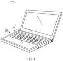
- FIG. 1 is a schematic diagram illustrating an electronic device 100 incorporating a virtual keyboard 104 on an electronic display 102, according to embodiments of the present disclosure.
- the electronic device 100 may be a mobile device, a laptop, a personal computer, a tablet, eReader, eWriter, a personal digital assistant, a watch, or any other suitable electronic device that may incorporate the virtual keyboard 104.
- the electronic display 102 may include any suitable display technology to display the virtual keyboard 104, such as a liquid crystal display (LCD), light-emitting diode (LED) display, or organic LED display.
- the electronic display 102 may be a touchscreen display.
- the electronic display 102 may include one or more sensors, such as capacitive or pressure sensors, to detect and indicate where a touch and/or pressure of a fingertip and/or writing utensil is applied to the electronic display 102.
- the electronic display 102 may display the virtual keyboard 104 having a set of keys, and each key of the set of keys in the virtual keyboard 104 may include one of the one or more sensors to sense when the respective key is selected.
- the virtual keyboard 104 may identify a character on the virtual keyboard 104 corresponding to the selected key.
- the virtual keyboard 104 may be optically projected onto a surface and/or may be displayed in a virtual reality, mixed reality, or augmented reality environment, and optical detection and analyzation of hand and finger motions may be interpreted as inputs to the virtual keyboard.
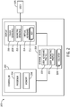
- FIG. 2 is a block diagram of a virtual keyboard system 200 that may be dynamically reconfigured, as described herein, according to embodiments of the present disclosure.
- the virtual keyboard system 200 includes a controller 202, a storage device 218, and an electronic display 208 that may generate a virtual keyboard 214, such as the electronic display 102 in FIG. 1 .
- the controller 202 may control operation of the display 208, may process touch data acquired by a touch sensor 210, and may process biometric data acquired by a biometric sensor 212.
- the controller 202 may be coupled to the display 208 by any suitable techniques for communicating sensor data and control signals between the controller 202 and the display 208, such as a wireless, optical, coaxial, wired, or other suitable connection.
- the display 208 may be similar to the electronic display 102 in FIG. 1 .
- the display 208 may include any suitable number of touch sensor(s) 210 and may include any suitable number of biometric sensor(s) 212.
- the display 208 may be a touchscreen display.
- the touch sensor(s) 210 may detect touch data indicating where a touch and/or pressure of a fingertip and/or writing utensil is applied to the display 208. The touch sensor(s) 210 may then transmit the touch data to the controller 202 for processing.
- the biometric sensor 212 may sense or detect a biometric data (e.g., a fingerprint, face recognition information, iris recognition information, a heartrate, electrocardiogram (ECG) information, body temperature, photoplethysmogram (PPG) information, electrodermal activity (EDA)) from the user 226.
- a biometric data e.g., a fingerprint, face recognition information, iris recognition information, a heartrate, electrocardiogram (ECG) information, body temperature, photoplethysmogram (PPG) information, electrodermal activity (EDA)
- ECG electrocardiogram
- PPG photoplethysmogram
- EDA electrodermal activity
- the controller 202 may include a number of elements to control operation of the display 208 and facilitate production and/or interpretation of the touch data and/or the biometric data.
- the controller 202 may include a processor 204 and a memory 206.
- the processor 204 may instruct the biometric sensor 212 and/or the touch sensor 210 to begin or end a sensing period.
- the processor 204 may process acquired touch data and/or biometric data to generate a user keyboard profile 220 and/or a user biometric profile 222.
- the user keyboard profile 220 may include a configuration of keys 216 for the virtual keyboard 214.
- the configuration may include a size, a shape, and a placement (i.e., location) for each key 216.
- the processor 204 may include one or more general purpose microprocessors, one or more application specific processors (ASICS), one or more field programmable logic arrays (FPGAs), or any other processing circuitry that facilitates managing the virtual keyboard system 200.
- ASICS application specific processors
- the processor 204 may determine keys 216 of the virtual keyboard 214 that were intended to be selected by the user 226, but were inadvertently missed due to the placement of the keys 216. Moreover, the processor 204 may dynamically reconfigure the virtual keyboard 214 to place the keys 216 intended to be selected by the user 226 where the user 226 expected them to be. As such, the processor 204 may include receiving and conversion circuitry. In particular, the processor 204 may receive touch data from the touch sensor(s) 210 representing a set of touch and/or pressure indications from the user 226 and process the touch data by, for example, identifying a set of character strings corresponding to the indications. In certain embodiments, one or more of the character strings may be a set of erased characters. Additionally or alternatively, one or more of the character strings may be a set of replacement characters.
- the processor 204 may compare the set of character strings to determine differences at one or more character locations of the set of character strings. For example, the processor 204 may receive touch data from the touch sensor(s) 210 and process the touch data to identify a first character string of erased characters and a second character string of replacement characters.
- the processor 204 may determine that the first character string and the second character string were input within a threshold time duration of less than five minutes (e.g., three minutes, one minute, thirty seconds, five seconds, and so on), which may be indicative of the user 226 selecting a key 216 (corresponding to an incorrect character in the first character string) by mistake, and correcting the mistake by deleting the incorrect key 216 and selecting a correct key 216 (corresponding to a correct character in the second character string).
- the threshold time duration may be less than five seconds.
- the processor 204 may parse the first character string and the second character string to identify similarities and/or differences between the first character string and the second character string.
- the first character string may be "macket" and the second character string may be "jacket”.
- the processor 204 may identify a first character (i.e., m) of the first string and a second character (i.e., j) of the second string as a key pair corresponding to a difference between the first character string and the second character string.
- the processor 204 may determine that the first character string and the second character string differ at only a single position, such as the first position in the example described above.
- the processor 204 may determine the characters in the key pair are located adjacent one another on a virtual keyboard 214 generated by the display 208. As a result, the processor 204 may determine that the user 226 incorrectly input the character "m" instead of the desired character "j". In certain embodiments, characters located adjacent on the virtual keyboard 214 may share at least a portion of a common border. Additionally or alternatively, characters located adjacent on the virtual keyboard 214 may have no intervening characters located between one another.
- the processor 204 may monitor the touch data for repeated occurrences of the same mistyped characters. For example, the processor 204 may count each instance of a mistyped character for a key pair. In some embodiments, the processor 204 may increment a counter 224 for a key pair including the first character of the first string and the second character of the second string and store the counter 224 for the key pair in the storage device 218. In certain embodiments, the counter 224 may be stored in the user keyboard profile 220. The processor 204 may compare the counter 224 value to a threshold value and adjust the display 208 for the virtual keyboard 214 when the counter meets or exceeds the threshold value. As a result, the processor 204 may dynamically reconfigure the virtual keyboard 214 after multiple repeated mistakes, instead of after single instances of mistyped characters.
- the processor 204 may continue to receive touch data from the touch sensor(s) 210 corresponding to a set of character strings. Additionally, the processor 204 may continue to increment a set of counters 224 for each key pair identified and store the set of counters 224 in the storage device 218. In certain embodiments, the processor 204 may monitor the set of counters 224 and compare a value of at least one of the set of counters 224 to a threshold value of at least ten (e.g., fifty, one hundred, one thousand, and so on). In some embodiments, the threshold value may be a dynamic threshold value, for example, starting at ten and increasing after the counter 224 reaches the dynamic threshold value.
- the processor 204 may reset the counter 224 once the threshold value is reached and begin incrementing the counter 224 again from zero. Additionally or alternatively, the processor 204 may reset the counter 224 after a threshold time duration. For example, the processor 204 may reset the counter 224 after a threshold time duration of at least one day (e.g., two days, a week, a month, and so on). As a result, the counter 224 may be reset periodically to prevent unintended reconfigurations of the virtual keyboard 214 because of a small number of errors accumulating over a long period of time into a larger number of errors which exceed a threshold value for the counter 224. After the counter meets the threshold value, the processor 204 may adjust the display 208 generating the virtual keyboard 214.
- the processor 204 may adjust a size, a shape, and/or a placement of at least one key 216 on the virtual keyboard 214 corresponding to one of the characters in the key pair. Additionally or alternatively, the processor 204 may adjust a size, a shape, and/or a placement of at least one key 216 on the virtual keyboard 214 corresponding to an adjacent key 216 of at least one of the characters in the key pair. After adjusting the display 208 generating the virtual keyboard 214, the processor 204 may store the adjusted display in a user keyboard profile 220 for the user 226.
- the processor 204 may store the adjusted display as a configuration of any number of keys 216 of the virtual keyboard 214 (e.g., the keys 216 that have been reconfigured from a default key configuration of the virtual keyboard 214, or each key 216 of the virtual keyboard 214).
- the configuration may include a size, a shape, and a placement for any number of keys 216 of the virtual keyboard 214.
- the processor 204 may associate a user biometric profile 22 with a user keyboard profile 220 in order to adjust the virtual keyboard 214 for multiple users.
- the processor 204 may receive the biometric data from the biometric sensor 212 representing a set of finger prints for the user 226, and process the biometric data by, for example, identifying friction ridges on at least one finger of the user 226.
- the processor 204 may generate a user biometric profile 222 for the user 226 based on the biometric data and/or the processed biometric data and store the user biometric profile 222 in storage device 218. Additionally or alternatively, the processor 204 may associate the user biometric profile 222 for the user 226 with the user keyboard profile 220 for the user 226.
- the processor 204 may determine when a change in the user 226 of the virtual keyboard system 200 occurs based on received biometric data from the biometric sensor 212. Moreover, the processor 204 may retrieve the stored user keyboard profile 220 for the user 226 and may adjust the display 208 generating the virtual keyboard 214 in response to the change in the user 226. In some embodiments, the processor 204 may receive a subsequent biometric data from the biometric sensor 212 and compare the subsequent biometric data to a set of previously received biometric data stored in a set of user biometric profiles 222. Additionally or alternatively, the processor 204 may process the subsequent biometric data and compare the processed subsequent biometric data to a set of previously processed biometric data stored in the set of user biometric profiles 222.
- the processor 204 may recognize a user of the virtual keyboard 214 based on the comparison. For example, the subsequent biometric data may match or correlate with one of the previously received biometric data in a corresponding user biometric profile 222. As a result, the processor 204 may receive the user keyboard profile 220 associated with the user biometric profile 222 and adjust a virtual keyboard 214 generated by the display 208 according to the user keyboard profile 220. Additionally or alternatively, the user 226 may input login information. For example, the processor 204 may recognize the user 226 based on login information received at the processor 204. The processor 204 may determine the login information corresponds to a user keyboard profile 220 and adjust the virtual keyboard 214 generated by the display 208 according to the user keyboard profile 220.
- the memory 206 may include one or more tangible, non-transitory, computer-readable media that store instruction executable by the processor 204 and/or data to be processed by the processor 204.
- the memory 206 may include random access memory (RAM), read-only memory (ROM), rewritable non-volatile memory such as flash memory, hard drives, optical discs, and/or the like.
- the memory 206 may store any suitable instruction to facilitate managing the virtual keyboard system 200.
- the memory 206 may store the touch data obtained via the touch sensor 210 and/or the biometric data obtained via the biometric sensor 212 and/or algorithms utilized by the processor 204 to generate user keyboard profile(s) 220 and user biometric profile(s) 222.
- the memory 206 may store a set of instructions and/or signal processing algorithms for the processor 204 to perform.
- the processor 204 may perform a signal processing algorithm on biometric data to generate a user biometric profile 222.
- the processor 204 may perform a signal processing algorithm to identify friction ridges in a fingerprint of at least one finger of a user 214.
- the storage device 218 may also include one or more tangible, non-transitory, computer-readable media that store instruction executable by the processor 204 and/or data to be process by the processor 204.
- the storage device 218 may include random access memory (RAM), read-only memory (ROM), one or more hard drives, flash memory, or the like.
- RAM random access memory
- ROM read-only memory
- the storage device 218 may store any suitable information to facilitate managing the virtual keyboard system 200.
- the storage device 218 may store touch data and/or biometric data to be processed by the controller 202 and may store processed touch data and processed biometric data.
- the virtual keyboard system 200 may include additional elements not shown in FIG. 2 , such as additional data acquisition and processing controls, display panels, user interfaces, and so forth.
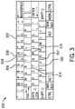
- FIG. 3 illustrates a virtual keyboard 300 prior to reconfiguration, according to embodiments of the present disclosure.
- the virtual keyboard 300 may include any suitable number of keys 302, such as alphanumeric character keys, punctuation keys, navigation keys, computer function keys, and command keys.
- Each of the keys 302 may include or be coupled to a touch sensor, such as touch sensor(s) 210 in FIG. 2 , to generate touch data based on a touch and/or pressure applied to the keys 302.
- a touch sensor such as touch sensor(s) 210 in FIG. 2
- each alphanumeric character key of the keys 302 may have a similar size and/or a similar shape.
- a central key may be surrounded by adjacent keys.
- central key 304 may be surrounded by adjacent keys 306, 308, 310, 312, 314, 316.
- the adjacent keys may be said to share a common border (e.g., the central key 304).
- no intervening keys may be located between each adjacent key and the central key.
- FIG. 4 illustrates a portion 400 of a virtual keyboard prior to reconfiguration, according to embodiments of the present disclosure.
- the portion 400 of the virtual keyboard may include a central key 402 and an adjacent key 404.
- the central key 402 and the adjacent key 404 may be alphanumeric character keys.
- the central key 402 and the adjacent key 404 may have a similar size and/or similar shape prior to reconfiguration.
- the central key 402 and the adjacent key 404 may be grouped into a key pair by the processor 204.
- each key pair may be a pair of keys that are commonly mistakenly selected in place of one another.
- two adjacent keys (e.g., 402, 404) may form a key pair.
- a processor such as processor 204 in FIG. 2 , may store a counter for the key pair corresponding to the central key 402 and the adjacent key 404, and increment the counter for the key pair each time the adjacent key 404 is incorrectly input for the central key 402, as described herein.
- FIG. 5 illustrates a virtual keyboard 500 after a single instance of reconfiguration, according to embodiments of the present disclosure.
- the virtual keyboard 500 includes a central key 502 and adjacent keys 504, 506. As illustrated, the central key and the adjacent keys 504, 506 are alphanumeric character keys.
- a processor such as processor 204 in FIG. 2 , may adjust and/or reconfigure a display of the virtual keyboard 500 based on a counter for a key pair including the central key 502 and an adjacent key (e.g., 504, 506) meeting a threshold value.
- the processor may increase a size (i.e., surface area) of the central key 502 and may decrease a size of the adjacent keys 504, 506. As illustrated, the processor may extend the surface area of the central key 502 in the direction of the adjacent keys 504, 506. Additionally or alternatively, the processor may only decrease a size (i.e., surface area) of the adjacent key corresponding to the character in the incremented key pair and/or increase a size of the central key.
- FIG. 6 illustrates a virtual keyboard 600 after multiple instances of reconfiguration, according to embodiments of the present disclosure.
- the virtual keyboard 600 includes any number of keys, such as keys 602, 604, 606, and 608.
- the keys 602, 604, 606, 608 differ in size, shape, and/or placement from a standard configuration, such as virtual keyboard 300 in FIG. 3 .
- the virtual keyboard 600 has undergone multiple instances of reconfiguration due to multiple counters associated with multiple key pairs meeting the respective threshold values.
- Each instance of reconfiguration may adjust a size, a shape, and a placement of one or more keys of the virtual keyboard 600.
- the user of the virtual keyboard 600 selects fewer and fewer incorrect keys due to the reconfiguration of the keys of the virtual keyboard 600 to meet the physical characteristics of the user.
- FIG. 7 is a flow diagram of a process 700 for dynamic reconfiguration of a virtual keyboard, such as the virtual keyboard 104 of FIG. 1 , according to embodiments of the present disclosure. While the process 700 is described as being performed by the processor 204, it should be understood that the process 700 may be performed by any suitable device that may control and/or communicate with components of the virtual keyboard system 200. Furthermore, while the process 700 is described using steps in a specific sequence, it should be understood that the present disclosure contemplates that the described steps may be performed in different sequences than the sequence illustrated, and certain described steps may be implemented by executing instructions stored in a tangible, non-transitory, computer-readable medium, such as the memory 206, using any suitable processing circuitry, such as the processor 204.
- a user such as user 226 in FIG. 2
- a set of touch data is generated and transmitted, for example, by the touch sensor(s) 210 of FIG. 2 .
- the set of touch data is received at a processor, such as the processor 204 of FIG. 2 .
- the processor 204 may process the set of touch data to generate a set of character strings.
- the set of character strings may include a first string of erased characters associated with the incorrectly input character string.
- the first string of erased characters is received (step 702), for example, at processor 204 of FIG. 2 .
- the user may delete the first character string and input a second, corrected character string.
- the processor 204 may process a second set of touch data to generate a second set of character strings including the second character string. Additionally or alternatively, the first set of character strings may include the second string of replacement characters.
- the second string of replacement of characters is generated and transmitted, for example, by the touch sensor(s) 210 of the display 208 in FIG. 2 .
- the second string of replacement characters is received (step 704), for example, at processor 204 of FIG. 2 .
- the processor 204 may determine a mistyped character and an intended character by comparison between the first string and the second string.
- the first string and the second string are compared (step 706), for example, at and/or by the processor 204 of FIG. 2 , to determine the mistyped character.
- the processor 204 identifies a character at each location of the first string and the second string.
- the processor 204 may group the characters at a same location in the first string and the second string. For example, the processor 204 may group the characters at the first location in a first group, may group the characters at the second location in a second group, and so on. Additionally, the processor 204 may analyze the groupings of the characters to determine whether any differences exist between the characters in the group.
- the processor 204 may determine a first character from the first string in the first group and a second character in the second string in the first group differ. In certain embodiments, the processor 204 may determine whether the differing characters in the group are located adjacent one another on the virtual keyboard, such as virtual keyboard 300 in FIG. 3 . For example, the processor 204 may determine the differing characters are adjacent characters on a virtual keyboard and determine the differing characters correspond to a mistyped character (i.e., deleted character) and an intended character (i.e., replacement character).
- a mistyped character i.e., deleted character
- an intended character i.e., replacement character
- the processor determines whether only a single difference exists between the first string and the second string based on the comparison (step 708). For example, the processor 204 may determine only a single difference exists in the groups of characters formed from the first string and the second string. As a result, the processor may increment a counter corresponding to a key pair for the first character and the second character (step 710). Additionally, the processor may store the counter for the key pair in the user keyboard profile for the user.
- the processor determines whether the counter for the key pair meets a threshold value (step 712).
- the threshold may be a dynamic threshold which increases each time the dynamic threshold is met. For example, a value for a dynamic threshold may begin at an initial value of ten and increase to a subsequent value of one hundred after the counter reaches the initial value. In certain instances, the dynamic threshold may increase exponentially. As a result, the processor 204 may adjust the virtual keyboard more frequently towards a beginning of a user's use of the virtual keyboard.
- the processor may adjust a configuration of the keys on the virtual keyboard in order to better accommodate a user making frequency mistakes for a specific key pair.
- the processor adjusts or instructs the display to adjust at least one key of the virtual keyboard (step 714).
- the processor may adjust a size, a shape, a placement, or any combination thereof for the at least one key.
- the processor may adjust a size, a shape, a placement, or any combination thereof for one or more adjacent keys of a central key in the key pair.
- the electronic display generating the virtual keyboard may adjust other keys of the virtual keyboard accordingly to display the adjusted size, shape, and/or placement of the keys of the virtual keyboard.
- process 700 may include additional steps.
- the processor may generate a user biometric profile to identify a user of the virtual keyboard and store a configuration of the virtual keyboard in a user keyboard profile associated with the user biometric profile.
- a biometric sensor such as biometric sensor 212 in FIG. 2
- a processor such as processor 204 in FIG. 2
- the processor may compare the set of biometric data to a set of biometric data stored in a user biometric profile, such as user biometric profile 222 in FIG. 2 , and recognize a user of the virtual keyboard based on the comparison.
- the processor may adjust at least one key of the virtual keyboard based on the recognition. For example, the processor may adjust at least one key of the virtual keyboard to match or correlate with a configuration included in a user keyboard profile associated with the recognized user biometric profile. Additionally or alternatively, the processor may process the set of biometric data received from the biometric sensor, may generate a new user biometric profile, and may store the new user biometric profile in a storage device, such as storage device 218 in FIG. 2 .
Landscapes
- Engineering & Computer Science (AREA)
- Theoretical Computer Science (AREA)
- General Engineering & Computer Science (AREA)
- Physics & Mathematics (AREA)
- General Physics & Mathematics (AREA)
- Human Computer Interaction (AREA)
- Computer Security & Cryptography (AREA)
- Computer Hardware Design (AREA)
- Software Systems (AREA)
- Multimedia (AREA)
- Health & Medical Sciences (AREA)
- General Health & Medical Sciences (AREA)
- Social Psychology (AREA)
- Input From Keyboards Or The Like (AREA)
- User Interface Of Digital Computer (AREA)
Abstract
Description
- The present disclosure relates generally to dynamically configuring a virtual keyboard.
- This section is intended to introduce the reader to various aspects of art that may be related to various aspects of the present disclosure, which are described and/or claimed below. This discussion is believed to be helpful in providing the reader with background information to facilitate a better understanding of the various aspects of the present disclosure. Accordingly, it should be understood that these statements are to be read in this light, and not as admissions of prior art.
- Virtual keyboards are typically displayed on an electronic display, and use a digital surface to receive input similar to a traditional keyboard. For example, a virtual keyboard can receive touch-based inputs corresponding to keys on the virtual keyboard. Due to differing physical characteristics of users, a standard size, shape, and/or placement of keys on the virtual keyboard may be difficult to use by different users. For example, users with smaller hands may find keys uncomfortably far apart while users with larger hands may frequently input incorrect keys due to inadequate spacing and/or size of keys. As a result, accuracy of typing, speed of typing, and comfort can be significantly diminished for certain users of a virtual keyboard.
- Various aspects of this disclosure may be better understood upon reading the following detailed description and upon reference to the drawings in which:
-
FIG. 1 is a schematic diagram of an electronic device incorporating a virtual keyboard, in accordance with an embodiment of the present disclosure; -
FIG. 2 is a block diagram of a virtual keyboard system, in accordance with an embodiment of the present disclosure; -
FIG. 3 is a schematic diagram of a virtual keyboard prior to reconfiguration, in accordance with an embodiment of the present disclosure; -
FIG. 4 is a schematic diagram of a portion of a virtual keyboard prior to reconfiguration, in accordance with an embodiment of the present disclosure; -
FIG. 5 is a schematic diagram of a virtual keyboard after a single instance of reconfiguration, in accordance with an embodiment of the present disclosure; -
FIG. 6 is a schematic diagram of a virtual keyboard after multiple instances of reconfiguration, in accordance with an embodiment of the present disclosure; and -
FIG. 7 is a flow diagram of a process for dynamic reconfiguration of a virtual keyboard system, in accordance with an embodiment of the present disclosure. - One or more specific embodiments of the present disclosure will be described below. In an effort to provide a concise description of these embodiments, not all features of an actual implementation are described in the specification. It should be appreciated that in the development of any such actual implementation, as in any engineering or design project, numerous implementation-specific decisions must be made to achieve the developer's specific goals, such as compliance with system-related and business-related constraints, which may vary from one implementation to another. Moreover, it should be appreciated that such a development effort might be complex and time consuming, but would nevertheless be a routine undertaking of design, fabrication, and manufacture for those of ordinary skill having the benefit of this disclosure.
- In an embodiment, a system includes an electronic display configured to display a virtual keyboard. In certain embodiments, the virtual keyboard includes a plurality of keys. In certain embodiments, the system also includes a processor communicatively coupled to the electronic display. In certain embodiments the processor is configured to receive a first string of erased characters, receive a second string of replacement characters, and compare the first string and the second string to determine a difference at corresponding character locations of the first string and the second string. In certain embodiments, the processor is also configured to increment a counter based on the difference, wherein the counter corresponds to a first character of the first string and a second character of the second string and adjust at least one of the plurality of keys of the virtual keyboard based on the counter meeting a threshold.
- In another embodiment, a method includes receiving a set of touch data and generating a user keyboard profile based on the set of touch data. In certain embodiments, the user keyboard profile includes a configuration of a virtual keyboard. In certain embodiments, the method also includes receiving a set of biometric data and generating a user biometric profile based on the set of biometric data, wherein the user biometric profile is associated with the user keyboard profile.
- In another embodiment, a method includes receiving a set of biometric data and recognizing a user based on the set of biometric data. In certain embodiments, the method also includes adjusting, based on the recognition, at least one of a plurality of keys of a virtual keyboard.
- With the preceding in mind,
FIG. 1 is a schematic diagram illustrating anelectronic device 100 incorporating avirtual keyboard 104 on anelectronic display 102, according to embodiments of the present disclosure. In some embodiments, theelectronic device 100 may be a mobile device, a laptop, a personal computer, a tablet, eReader, eWriter, a personal digital assistant, a watch, or any other suitable electronic device that may incorporate thevirtual keyboard 104. - The
electronic display 102 may include any suitable display technology to display thevirtual keyboard 104, such as a liquid crystal display (LCD), light-emitting diode (LED) display, or organic LED display. In certain embodiments, theelectronic display 102 may be a touchscreen display. For example, theelectronic display 102 may include one or more sensors, such as capacitive or pressure sensors, to detect and indicate where a touch and/or pressure of a fingertip and/or writing utensil is applied to theelectronic display 102. In certain embodiments, theelectronic display 102 may display thevirtual keyboard 104 having a set of keys, and each key of the set of keys in thevirtual keyboard 104 may include one of the one or more sensors to sense when the respective key is selected. In response to receiving an indication from the one or more sensors that a key is selected, thevirtual keyboard 104 may identify a character on thevirtual keyboard 104 corresponding to the selected key. Alternatively, thevirtual keyboard 104 may be optically projected onto a surface and/or may be displayed in a virtual reality, mixed reality, or augmented reality environment, and optical detection and analyzation of hand and finger motions may be interpreted as inputs to the virtual keyboard. -
FIG. 2 is a block diagram of avirtual keyboard system 200 that may be dynamically reconfigured, as described herein, according to embodiments of the present disclosure. In certain embodiments, thevirtual keyboard system 200 includes acontroller 202, astorage device 218, and anelectronic display 208 that may generate avirtual keyboard 214, such as theelectronic display 102 inFIG. 1 . Thecontroller 202 may control operation of thedisplay 208, may process touch data acquired by atouch sensor 210, and may process biometric data acquired by abiometric sensor 212. Thecontroller 202 may be coupled to thedisplay 208 by any suitable techniques for communicating sensor data and control signals between thecontroller 202 and thedisplay 208, such as a wireless, optical, coaxial, wired, or other suitable connection. - The
display 208 may be similar to theelectronic display 102 inFIG. 1 . Thedisplay 208 may include any suitable number of touch sensor(s) 210 and may include any suitable number of biometric sensor(s) 212. In certain embodiments, thedisplay 208 may be a touchscreen display. For example, the touch sensor(s) 210 may detect touch data indicating where a touch and/or pressure of a fingertip and/or writing utensil is applied to thedisplay 208. The touch sensor(s) 210 may then transmit the touch data to thecontroller 202 for processing. - The
biometric sensor 212 may sense or detect a biometric data (e.g., a fingerprint, face recognition information, iris recognition information, a heartrate, electrocardiogram (ECG) information, body temperature, photoplethysmogram (PPG) information, electrodermal activity (EDA)) from theuser 226. For example, thebiometric sensor 212 may detect biometric data from a fingerprint of theuser 226. Thebiometric sensor 212 may then transmit the biometric data to thecontroller 202 for processing. - As will be appreciated, the
controller 202 may include a number of elements to control operation of thedisplay 208 and facilitate production and/or interpretation of the touch data and/or the biometric data. For instance, as illustrated, thecontroller 202 may include aprocessor 204 and amemory 206. Theprocessor 204 may instruct thebiometric sensor 212 and/or thetouch sensor 210 to begin or end a sensing period. Additionally, theprocessor 204 may process acquired touch data and/or biometric data to generate auser keyboard profile 220 and/or a userbiometric profile 222. Theuser keyboard profile 220 may include a configuration ofkeys 216 for thevirtual keyboard 214. For example, the configuration may include a size, a shape, and a placement (i.e., location) for eachkey 216. Additionally, theprocessor 204 may include one or more general purpose microprocessors, one or more application specific processors (ASICS), one or more field programmable logic arrays (FPGAs), or any other processing circuitry that facilitates managing thevirtual keyboard system 200. - The
processor 204 may determinekeys 216 of thevirtual keyboard 214 that were intended to be selected by theuser 226, but were inadvertently missed due to the placement of thekeys 216. Moreover, theprocessor 204 may dynamically reconfigure thevirtual keyboard 214 to place thekeys 216 intended to be selected by theuser 226 where theuser 226 expected them to be. As such, theprocessor 204 may include receiving and conversion circuitry. In particular, theprocessor 204 may receive touch data from the touch sensor(s) 210 representing a set of touch and/or pressure indications from theuser 226 and process the touch data by, for example, identifying a set of character strings corresponding to the indications. In certain embodiments, one or more of the character strings may be a set of erased characters. Additionally or alternatively, one or more of the character strings may be a set of replacement characters. - In some embodiments, the
processor 204 may compare the set of character strings to determine differences at one or more character locations of the set of character strings. For example, theprocessor 204 may receive touch data from the touch sensor(s) 210 and process the touch data to identify a first character string of erased characters and a second character string of replacement characters. Additionally, theprocessor 204 may determine that the first character string and the second character string were input within a threshold time duration of less than five minutes (e.g., three minutes, one minute, thirty seconds, five seconds, and so on), which may be indicative of theuser 226 selecting a key 216 (corresponding to an incorrect character in the first character string) by mistake, and correcting the mistake by deleting theincorrect key 216 and selecting a correct key 216 (corresponding to a correct character in the second character string). In certain embodiments, the threshold time duration may be less than five seconds. - In particular, the
processor 204 may parse the first character string and the second character string to identify similarities and/or differences between the first character string and the second character string. For example, the first character string may be "macket" and the second character string may be "jacket". As a result, theprocessor 204 may identify a first character (i.e., m) of the first string and a second character (i.e., j) of the second string as a key pair corresponding to a difference between the first character string and the second character string. In certain embodiments, theprocessor 204 may determine that the first character string and the second character string differ at only a single position, such as the first position in the example described above. Additionally, theprocessor 204 may determine the characters in the key pair are located adjacent one another on avirtual keyboard 214 generated by thedisplay 208. As a result, theprocessor 204 may determine that theuser 226 incorrectly input the character "m" instead of the desired character "j". In certain embodiments, characters located adjacent on thevirtual keyboard 214 may share at least a portion of a common border. Additionally or alternatively, characters located adjacent on thevirtual keyboard 214 may have no intervening characters located between one another. - The
processor 204 may monitor the touch data for repeated occurrences of the same mistyped characters. For example, theprocessor 204 may count each instance of a mistyped character for a key pair. In some embodiments, theprocessor 204 may increment acounter 224 for a key pair including the first character of the first string and the second character of the second string and store thecounter 224 for the key pair in thestorage device 218. In certain embodiments, thecounter 224 may be stored in theuser keyboard profile 220. Theprocessor 204 may compare thecounter 224 value to a threshold value and adjust thedisplay 208 for thevirtual keyboard 214 when the counter meets or exceeds the threshold value. As a result, theprocessor 204 may dynamically reconfigure thevirtual keyboard 214 after multiple repeated mistakes, instead of after single instances of mistyped characters. - The
processor 204 may continue to receive touch data from the touch sensor(s) 210 corresponding to a set of character strings. Additionally, theprocessor 204 may continue to increment a set ofcounters 224 for each key pair identified and store the set ofcounters 224 in thestorage device 218. In certain embodiments, theprocessor 204 may monitor the set ofcounters 224 and compare a value of at least one of the set ofcounters 224 to a threshold value of at least ten (e.g., fifty, one hundred, one thousand, and so on). In some embodiments, the threshold value may be a dynamic threshold value, for example, starting at ten and increasing after thecounter 224 reaches the dynamic threshold value. Alternatively, theprocessor 204 may reset thecounter 224 once the threshold value is reached and begin incrementing thecounter 224 again from zero. Additionally or alternatively, theprocessor 204 may reset thecounter 224 after a threshold time duration. For example, theprocessor 204 may reset thecounter 224 after a threshold time duration of at least one day (e.g., two days, a week, a month, and so on). As a result, thecounter 224 may be reset periodically to prevent unintended reconfigurations of thevirtual keyboard 214 because of a small number of errors accumulating over a long period of time into a larger number of errors which exceed a threshold value for thecounter 224. After the counter meets the threshold value, theprocessor 204 may adjust thedisplay 208 generating thevirtual keyboard 214. - For example, the
processor 204 may adjust a size, a shape, and/or a placement of at least one key 216 on thevirtual keyboard 214 corresponding to one of the characters in the key pair. Additionally or alternatively, theprocessor 204 may adjust a size, a shape, and/or a placement of at least one key 216 on thevirtual keyboard 214 corresponding to anadjacent key 216 of at least one of the characters in the key pair. After adjusting thedisplay 208 generating thevirtual keyboard 214, theprocessor 204 may store the adjusted display in auser keyboard profile 220 for theuser 226. For example, theprocessor 204 may store the adjusted display as a configuration of any number ofkeys 216 of the virtual keyboard 214 (e.g., thekeys 216 that have been reconfigured from a default key configuration of thevirtual keyboard 214, or each key 216 of the virtual keyboard 214). In particular, the configuration may include a size, a shape, and a placement for any number ofkeys 216 of thevirtual keyboard 214. - The
processor 204 may associate a user biometric profile 22 with auser keyboard profile 220 in order to adjust thevirtual keyboard 214 for multiple users. For example, theprocessor 204 may receive the biometric data from thebiometric sensor 212 representing a set of finger prints for theuser 226, and process the biometric data by, for example, identifying friction ridges on at least one finger of theuser 226. In certain embodiments, theprocessor 204 may generate a userbiometric profile 222 for theuser 226 based on the biometric data and/or the processed biometric data and store the userbiometric profile 222 instorage device 218. Additionally or alternatively, theprocessor 204 may associate the userbiometric profile 222 for theuser 226 with theuser keyboard profile 220 for theuser 226. - The
processor 204 may determine when a change in theuser 226 of thevirtual keyboard system 200 occurs based on received biometric data from thebiometric sensor 212. Moreover, theprocessor 204 may retrieve the storeduser keyboard profile 220 for theuser 226 and may adjust thedisplay 208 generating thevirtual keyboard 214 in response to the change in theuser 226. In some embodiments, theprocessor 204 may receive a subsequent biometric data from thebiometric sensor 212 and compare the subsequent biometric data to a set of previously received biometric data stored in a set of user biometric profiles 222. Additionally or alternatively, theprocessor 204 may process the subsequent biometric data and compare the processed subsequent biometric data to a set of previously processed biometric data stored in the set of user biometric profiles 222. In certain embodiments, theprocessor 204 may recognize a user of thevirtual keyboard 214 based on the comparison. For example, the subsequent biometric data may match or correlate with one of the previously received biometric data in a corresponding userbiometric profile 222. As a result, theprocessor 204 may receive theuser keyboard profile 220 associated with the userbiometric profile 222 and adjust avirtual keyboard 214 generated by thedisplay 208 according to theuser keyboard profile 220. Additionally or alternatively, theuser 226 may input login information. For example, theprocessor 204 may recognize theuser 226 based on login information received at theprocessor 204. Theprocessor 204 may determine the login information corresponds to auser keyboard profile 220 and adjust thevirtual keyboard 214 generated by thedisplay 208 according to theuser keyboard profile 220. - The
memory 206 may include one or more tangible, non-transitory, computer-readable media that store instruction executable by theprocessor 204 and/or data to be processed by theprocessor 204. For example, thememory 206 may include random access memory (RAM), read-only memory (ROM), rewritable non-volatile memory such as flash memory, hard drives, optical discs, and/or the like. Thememory 206 may store any suitable instruction to facilitate managing thevirtual keyboard system 200. For example, thememory 206 may store the touch data obtained via thetouch sensor 210 and/or the biometric data obtained via thebiometric sensor 212 and/or algorithms utilized by theprocessor 204 to generate user keyboard profile(s) 220 and user biometric profile(s) 222. In some embodiments, thememory 206 may store a set of instructions and/or signal processing algorithms for theprocessor 204 to perform. In particular, theprocessor 204 may perform a signal processing algorithm on biometric data to generate a userbiometric profile 222. For example, theprocessor 204 may perform a signal processing algorithm to identify friction ridges in a fingerprint of at least one finger of auser 214. - The
storage device 218 may also include one or more tangible, non-transitory, computer-readable media that store instruction executable by theprocessor 204 and/or data to be process by theprocessor 204. For example, thestorage device 218 may include random access memory (RAM), read-only memory (ROM), one or more hard drives, flash memory, or the like. Thestorage device 218 may store any suitable information to facilitate managing thevirtual keyboard system 200. For example, thestorage device 218 may store touch data and/or biometric data to be processed by thecontroller 202 and may store processed touch data and processed biometric data. In certain embodiments, thevirtual keyboard system 200 may include additional elements not shown inFIG. 2 , such as additional data acquisition and processing controls, display panels, user interfaces, and so forth. - With the preceding in mind,
FIG. 3 illustrates avirtual keyboard 300 prior to reconfiguration, according to embodiments of the present disclosure. Thevirtual keyboard 300 may include any suitable number ofkeys 302, such as alphanumeric character keys, punctuation keys, navigation keys, computer function keys, and command keys. Each of thekeys 302 may include or be coupled to a touch sensor, such as touch sensor(s) 210 inFIG. 2 , to generate touch data based on a touch and/or pressure applied to thekeys 302. In certain embodiments, prior to reconfiguration, each alphanumeric character key of thekeys 302 may have a similar size and/or a similar shape. A central key may be surrounded by adjacent keys. For example,central key 304 may be surrounded byadjacent keys - With the preceding in mind,
FIG. 4 illustrates aportion 400 of a virtual keyboard prior to reconfiguration, according to embodiments of the present disclosure. Theportion 400 of the virtual keyboard may include acentral key 402 and anadjacent key 404. As illustrated, thecentral key 402 and theadjacent key 404 may be alphanumeric character keys. In certain embodiments, thecentral key 402 and theadjacent key 404 may have a similar size and/or similar shape prior to reconfiguration. Thecentral key 402 and theadjacent key 404 may be grouped into a key pair by theprocessor 204. In particular, each key pair may be a pair of keys that are commonly mistakenly selected in place of one another. For example, two adjacent keys (e.g., 402, 404) may form a key pair. A processor, such asprocessor 204 inFIG. 2 , may store a counter for the key pair corresponding to thecentral key 402 and theadjacent key 404, and increment the counter for the key pair each time theadjacent key 404 is incorrectly input for thecentral key 402, as described herein. - With the preceding in mind,
FIG. 5 illustrates avirtual keyboard 500 after a single instance of reconfiguration, according to embodiments of the present disclosure. Thevirtual keyboard 500 includes acentral key 502 andadjacent keys adjacent keys processor 204 inFIG. 2 , may adjust and/or reconfigure a display of thevirtual keyboard 500 based on a counter for a key pair including thecentral key 502 and an adjacent key (e.g., 504, 506) meeting a threshold value. For example, each time theuser 214 mistakenly enters the adjacent key (e.g., 504, 506) instead of thecentral key 502, and replaces the adjacent key character in a first character string of erased characters and replaces the adjacent key character with the central key character in a second character string of replacement characters, the counter associated with the corresponding key pair may be incremented. As a result of the counter associated with the key pair meeting the respective threshold value, and as depicted inFIG. 5 , the processor may increase a size (i.e., surface area) of thecentral key 502 and may decrease a size of theadjacent keys central key 502 in the direction of theadjacent keys - With the preceding in mind,
FIG. 6 illustrates avirtual keyboard 600 after multiple instances of reconfiguration, according to embodiments of the present disclosure. Thevirtual keyboard 600 includes any number of keys, such askeys keys virtual keyboard 300 inFIG. 3 . As depicted inFIG. 6 , thevirtual keyboard 600 has undergone multiple instances of reconfiguration due to multiple counters associated with multiple key pairs meeting the respective threshold values. Each instance of reconfiguration may adjust a size, a shape, and a placement of one or more keys of thevirtual keyboard 600. As a result, the user of thevirtual keyboard 600 selects fewer and fewer incorrect keys due to the reconfiguration of the keys of thevirtual keyboard 600 to meet the physical characteristics of the user. - With the preceding in mind,
FIG. 7 is a flow diagram of aprocess 700 for dynamic reconfiguration of a virtual keyboard, such as thevirtual keyboard 104 ofFIG. 1 , according to embodiments of the present disclosure. While theprocess 700 is described as being performed by theprocessor 204, it should be understood that theprocess 700 may be performed by any suitable device that may control and/or communicate with components of thevirtual keyboard system 200. Furthermore, while theprocess 700 is described using steps in a specific sequence, it should be understood that the present disclosure contemplates that the described steps may be performed in different sequences than the sequence illustrated, and certain described steps may be implemented by executing instructions stored in a tangible, non-transitory, computer-readable medium, such as thememory 206, using any suitable processing circuitry, such as theprocessor 204. - In this
process 700, a user, such asuser 226 inFIG. 2 , may be typing on a virtual keyboard, such asvirtual keyboard 214, and incorrectly input a character in a character string and subsequently replace the incorrect character with the correct character by erasing the character string or a portion of the character string. As a result of the typing and interaction with the virtual keyboard, a set of touch data is generated and transmitted, for example, by the touch sensor(s) 210 ofFIG. 2 . In some embodiments, the set of touch data is received at a processor, such as theprocessor 204 ofFIG. 2 . Additionally, theprocessor 204 may process the set of touch data to generate a set of character strings. In certain embodiments, the set of character strings may include a first string of erased characters associated with the incorrectly input character string. The first string of erased characters is received (step 702), for example, atprocessor 204 ofFIG. 2 . - After incorrectly typing the first string, the user may delete the first character string and input a second, corrected character string. In some embodiments, the
processor 204 may process a second set of touch data to generate a second set of character strings including the second character string. Additionally or alternatively, the first set of character strings may include the second string of replacement characters. The second string of replacement of characters is generated and transmitted, for example, by the touch sensor(s) 210 of thedisplay 208 inFIG. 2 . The second string of replacement characters is received (step 704), for example, atprocessor 204 ofFIG. 2 . - Next, the
processor 204 may determine a mistyped character and an intended character by comparison between the first string and the second string. The first string and the second string are compared (step 706), for example, at and/or by theprocessor 204 ofFIG. 2 , to determine the mistyped character. In particular, theprocessor 204 identifies a character at each location of the first string and the second string. In certain embodiments, theprocessor 204 may group the characters at a same location in the first string and the second string. For example, theprocessor 204 may group the characters at the first location in a first group, may group the characters at the second location in a second group, and so on. Additionally, theprocessor 204 may analyze the groupings of the characters to determine whether any differences exist between the characters in the group. For example, theprocessor 204 may determine a first character from the first string in the first group and a second character in the second string in the first group differ. In certain embodiments, theprocessor 204 may determine whether the differing characters in the group are located adjacent one another on the virtual keyboard, such asvirtual keyboard 300 inFIG. 3 . For example, theprocessor 204 may determine the differing characters are adjacent characters on a virtual keyboard and determine the differing characters correspond to a mistyped character (i.e., deleted character) and an intended character (i.e., replacement character). - In order to verify that the mistyped character was a mistake associated with a mistyped character and not a choice by the user to replace a character string altogether, the processor determines whether only a single difference exists between the first string and the second string based on the comparison (step 708). For example, the
processor 204 may determine only a single difference exists in the groups of characters formed from the first string and the second string. As a result, the processor may increment a counter corresponding to a key pair for the first character and the second character (step 710). Additionally, the processor may store the counter for the key pair in the user keyboard profile for the user. - The processor determines whether the counter for the key pair meets a threshold value (step 712). In certain embodiments, the threshold may be a dynamic threshold which increases each time the dynamic threshold is met. For example, a value for a dynamic threshold may begin at an initial value of ten and increase to a subsequent value of one hundred after the counter reaches the initial value. In certain instances, the dynamic threshold may increase exponentially. As a result, the
processor 204 may adjust the virtual keyboard more frequently towards a beginning of a user's use of the virtual keyboard. - Next, the processor may adjust a configuration of the keys on the virtual keyboard in order to better accommodate a user making frequency mistakes for a specific key pair. The processor adjusts or instructs the display to adjust at least one key of the virtual keyboard (step 714). In some embodiments, the processor may adjust a size, a shape, a placement, or any combination thereof for the at least one key. Additionally or alternatively, the processor may adjust a size, a shape, a placement, or any combination thereof for one or more adjacent keys of a central key in the key pair. The electronic display generating the virtual keyboard may adjust other keys of the virtual keyboard accordingly to display the adjusted size, shape, and/or placement of the keys of the virtual keyboard.
- In certain embodiments,
process 700 may include additional steps. In certain embodiments, the processor may generate a user biometric profile to identify a user of the virtual keyboard and store a configuration of the virtual keyboard in a user keyboard profile associated with the user biometric profile. For example, a biometric sensor, such asbiometric sensor 212 inFIG. 2 , may generate and transmit a set of biometric data for a user. In some embodiments, a processor, such asprocessor 204 inFIG. 2 , may receive the set of biometric data and may process the biometric data. The processor may compare the set of biometric data to a set of biometric data stored in a user biometric profile, such as userbiometric profile 222 inFIG. 2 , and recognize a user of the virtual keyboard based on the comparison. Additionally, the processor may adjust at least one key of the virtual keyboard based on the recognition. For example, the processor may adjust at least one key of the virtual keyboard to match or correlate with a configuration included in a user keyboard profile associated with the recognized user biometric profile. Additionally or alternatively, the processor may process the set of biometric data received from the biometric sensor, may generate a new user biometric profile, and may store the new user biometric profile in a storage device, such asstorage device 218 inFIG. 2 . - While only certain features of the disclosure have been illustrated and described herein, many modifications and changes will occur to those skilled in the art. For example, while the embodiments described herein include reconfiguration of virtual keyboard systems, substantially similar benefits provided by the present invention may be provided to similar virtual display systems for other types of controls. For example, virtual control systems for audio engineering, operation of virtual musical instruments, graphic design, augmented reality, virtual reality, and any other suitable virtual display systems may be reconfigured using the systems and methods described herein.
- The techniques presented and claimed herein are referenced and applied to material objects and concrete examples of a practical nature that demonstrably improve the present technical field and, as such, are not abstract, intangible or purely theoretical. Further, if any claims appended to the end of this specification contain one or more elements designated as "means for [perform]ing [a function]..." or "step for [perform]ing [a function]...", it is intended that such elements are to be interpreted under 35 U.S.C. § 112(f). However, for any claims containing elements designated in any other manner, it is intended that such elements are not to be interpreted under 35 U.S.C. § 112(f).
Claims (15)
- A system, comprising:an electronic display configured to display a virtual keyboard, wherein the virtual keyboard comprises a plurality of keys; anda processor communicatively coupled to the electronic display and configured to:receive a first string of erased characters;receive a second string of replacement characters;compare the first string and the second string to determine a difference at corresponding character locations of the first string and the second string;increment a counter based on the difference, wherein the counter corresponds to a first character of the first string and a second character of the second string; andadjust at least one of the plurality of keys of the virtual keyboard based on the counter meeting a threshold.
- The system of claim 1, comprising a biometric sensor configured to generate a set of biometric data, wherein the processor is configured to:receive the set of biometric data;identify a user based on the set of biometric data; andadjust at least one of the plurality of keys of the virtual keyboard based on the user.
- The system of any of the preceding claims, wherein adjusting at least one of the plurality of keys of the virtual keyboard comprises altering a size of at least one of the plurality of keys, a shape of at least one of the plurality of keys, or both.
- The system of any of the preceding claims, wherein the processor is configured to determine that the second character is located adjacent the first character on the virtual keyboard.
- The system of any of the preceding claims, wherein the corresponding character locations comprises a single location of the first string and a single location of the second string.
- The system of any of the preceding claims, wherein adjusting at least one of the plurality of keys of the virtual keyboard comprises altering a placement of one or more of the plurality of keys on the virtual keyboard.
- The system of any of the preceding claims, wherein the threshold is a dynamic threshold.
- The system of claim 7, wherein the dynamic threshold increases in response to the counter meeting the dynamic threshold.
- A method, comprising:receiving a set of touch data;generating a user keyboard profile based on the set of touch data, wherein the user keyboard profile comprises a configuration of a virtual keyboard;receiving a set of biometric data; andgenerating a user biometric profile based on the set of biometric data, wherein the user biometric profile is associated with the user keyboard profile.
- The method of claim 9, wherein the set of touch data comprises a first string of erased characters and a second string of replacement characters, wherein the method comprises:comparing the first string and the second string to determine a difference at corresponding character locations of the first string and the second string; andadjusting the configuration of the virtual keyboard based on the comparison.
- The method of claim 10, wherein adjusting the configuration of the virtual keyboard comprises altering a size of a first key of the virtual keyboard.
- The method of claim 11, wherein altering the size of the first key comprises increasing the size of the first key.
- The method of claim 11, wherein adjusting the configuration of the virtual keyboard comprises altering a size of a second key of the virtual keyboard.
- The method of claim 13, wherein altering the size of the second key comprises decreasing the size of the second key.
- The method of any of claims 11-14, wherein adjusting the configuration of the virtual keyboard comprises altering a shape of the first key of the virtual keyboard.
Applications Claiming Priority (1)
| Application Number | Priority Date | Filing Date | Title |
|---|---|---|---|
| US16/808,138 US11216182B2 (en) | 2020-03-03 | 2020-03-03 | Dynamic configuration of a virtual keyboard |
Publications (2)
| Publication Number | Publication Date |
|---|---|
| EP3876074A1 true EP3876074A1 (en) | 2021-09-08 |
| EP3876074B1 EP3876074B1 (en) | 2023-12-06 |
Family
ID=71097658
Family Applications (1)
| Application Number | Title | Priority Date | Filing Date |
|---|---|---|---|
| EP20214422.6A Active EP3876074B1 (en) | 2020-03-03 | 2020-12-16 | Dynamic configuration of a virtual keyboard |
Country Status (6)
| Country | Link |
|---|---|
| US (2) | US11216182B2 (en) |
| EP (1) | EP3876074B1 (en) |
| JP (1) | JP7750650B2 (en) |
| KR (1) | KR20210111670A (en) |
| CN (1) | CN113342250A (en) |
| TW (1) | TWI868276B (en) |
Families Citing this family (1)
| Publication number | Priority date | Publication date | Assignee | Title |
|---|---|---|---|---|
| US11842024B2 (en) * | 2020-09-30 | 2023-12-12 | Business Objects Software Ltd. | System and method for intelligent polymorphism of user interface |
Citations (2)
| Publication number | Priority date | Publication date | Assignee | Title |
|---|---|---|---|---|
| US20130019191A1 (en) * | 2011-07-11 | 2013-01-17 | International Business Machines Corporation | Dynamically customizable touch screen keyboard for adapting to user physiology |
| US9548012B1 (en) * | 2012-08-29 | 2017-01-17 | Amazon Technologies, Inc. | Adaptive ergonomic keyboard |
Family Cites Families (70)
| Publication number | Priority date | Publication date | Assignee | Title |
|---|---|---|---|---|
| US5963671A (en) * | 1991-11-27 | 1999-10-05 | International Business Machines Corporation | Enhancement of soft keyboard operations using trigram prediction |
| US5748177A (en) * | 1995-06-07 | 1998-05-05 | Semantic Compaction Systems | Dynamic keyboard and method for dynamically redefining keys on a keyboard |
| US7844914B2 (en) * | 2004-07-30 | 2010-11-30 | Apple Inc. | Activating virtual keys of a touch-screen virtual keyboard |
| US6266377B1 (en) * | 1998-05-12 | 2001-07-24 | Nortel Networks Limited | Method of timing recovery convergence monitoring in modems |
| US6378234B1 (en) * | 1999-04-09 | 2002-04-30 | Ching-Hsing Luo | Sequential stroke keyboard |
| ATE443946T1 (en) * | 1999-05-27 | 2009-10-15 | Tegic Communications Inc | KEYBOARD SYSTEM WITH AUTOMATIC CORRECTION |
| US7030863B2 (en) * | 2000-05-26 | 2006-04-18 | America Online, Incorporated | Virtual keyboard system with automatic correction |
| US6512838B1 (en) * | 1999-09-22 | 2003-01-28 | Canesta, Inc. | Methods for enhancing performance and data acquired from three-dimensional image systems |
| EP1316055A4 (en) * | 2000-05-29 | 2006-10-04 | Vkb Inc | Virtual data entry device and method for input of alphanumeric and other data |
| US7536557B2 (en) * | 2001-03-22 | 2009-05-19 | Ensign Holdings | Method for biometric authentication through layering biometric traits |
| US20030018522A1 (en) * | 2001-07-20 | 2003-01-23 | Psc Scanning, Inc. | Biometric system and method for identifying a customer upon entering a retail establishment |
| US6684166B2 (en) * | 2002-05-02 | 2004-01-27 | International Business Machines Corporation | Pressure sensitive keyboard |
| US7151530B2 (en) * | 2002-08-20 | 2006-12-19 | Canesta, Inc. | System and method for determining an input selected by a user through a virtual interface |
| BR0300474A (en) * | 2003-02-25 | 2004-11-03 | Banco Itau S A | Method of generating a virtual keyboard for entering a user's security password or positive identification |
| US20040183833A1 (en) * | 2003-03-19 | 2004-09-23 | Chua Yong Tong | Keyboard error reduction method and apparatus |
| US6830396B2 (en) * | 2003-03-31 | 2004-12-14 | Francis N. Kurriss | Keyboard configuration system |
| JP2005267424A (en) | 2004-03-19 | 2005-09-29 | Fujitsu Ltd | Data input device, information processing device, data input method, and data input program |
| US8065525B2 (en) * | 2004-09-22 | 2011-11-22 | Bekad Mgmt. Ii, Llc | Device with built-in user authentication and method for user authentication and identity theft protection |
| US7484173B2 (en) * | 2005-10-18 | 2009-01-27 | International Business Machines Corporation | Alternative key pad layout for enhanced security |
| US9235733B2 (en) * | 2006-08-11 | 2016-01-12 | J. Douglas Birdwell | Mobile biometrics information collection and identification |
| US9110590B2 (en) * | 2007-09-19 | 2015-08-18 | Typesoft Technologies, Inc. | Dynamically located onscreen keyboard |
| US8134449B2 (en) * | 2007-10-23 | 2012-03-13 | Minebea Co., Ltd | Method and system for biometric keyboard |
| US20090183098A1 (en) * | 2008-01-14 | 2009-07-16 | Dell Products, Lp | Configurable Keyboard |
| US10402087B2 (en) * | 2008-09-29 | 2019-09-03 | Intel Corporation | Adaptive keyboard for ultra-mobile devices |
| US8300023B2 (en) | 2009-04-10 | 2012-10-30 | Qualcomm Incorporated | Virtual keypad generator with learning capabilities |
| US20100281268A1 (en) * | 2009-04-30 | 2010-11-04 | Microsoft Corporation | Personalizing an Adaptive Input Device |
| US20110060984A1 (en) * | 2009-09-06 | 2011-03-10 | Lee Yung-Chao | Method and apparatus for word prediction of text input by assigning different priorities to words on a candidate word list according to how many letters have been entered so far by a user |
| WO2011037149A1 (en) * | 2009-09-25 | 2011-03-31 | 日本電気株式会社 | Input receiving device, input receiving method, recording medium, and mobile communication terminal |
| US8812972B2 (en) * | 2009-09-30 | 2014-08-19 | At&T Intellectual Property I, L.P. | Dynamic generation of soft keyboards for mobile devices |
| US20110267278A1 (en) * | 2010-04-29 | 2011-11-03 | Sony Ericsson Mobile Communications Ab | Adaptive soft keyboard |
| US8648809B2 (en) * | 2010-06-16 | 2014-02-11 | International Business Machines Corporation | Reconfiguration of virtual keyboard |
| EP2616908A2 (en) * | 2010-09-15 | 2013-07-24 | Jeffrey R. Spetalnick | Methods of and systems for reducing keyboard data entry errors |
| US20130275907A1 (en) * | 2010-10-14 | 2013-10-17 | University of Technology ,Sydney | Virtual keyboard |
| US20120166995A1 (en) * | 2010-12-24 | 2012-06-28 | Telefonaktiebolaget L M Ericsson (Publ) | Smart virtual keyboard for touchscreen devices |
| US20140368455A1 (en) * | 2011-03-15 | 2014-12-18 | Logitech Europe Sa | Control method for a function of a touchpad |
| US9430145B2 (en) * | 2011-04-06 | 2016-08-30 | Samsung Electronics Co., Ltd. | Dynamic text input using on and above surface sensing of hands and fingers |
| US20160132119A1 (en) * | 2014-11-12 | 2016-05-12 | Will John Temple | Multidirectional button, key, and keyboard |
| US9417754B2 (en) * | 2011-08-05 | 2016-08-16 | P4tents1, LLC | User interface system, method, and computer program product |
| TWI453628B (en) * | 2012-01-12 | 2014-09-21 | Amtran Technology Co Ltd | Method for adaptively adjusting size of virtual keys and display device usnig the same |
| US8934779B2 (en) * | 2012-02-10 | 2015-01-13 | Source Photonics, Inc. | Operational status indicators in an optical transceiver using dynamic thresholds |
| US20130222247A1 (en) * | 2012-02-29 | 2013-08-29 | Eric Liu | Virtual keyboard adjustment based on user input offset |
| JP5910345B2 (en) * | 2012-06-21 | 2016-04-27 | 富士通株式会社 | Character input program, information processing apparatus, and character input method |
| US9135135B2 (en) * | 2012-06-28 | 2015-09-15 | Sap Se | Method and system for auto-adjusting thresholds for efficient monitoring of system metrics |
| US9041654B2 (en) * | 2012-07-18 | 2015-05-26 | Sap Se | Virtual touchscreen keyboards |
| US9305229B2 (en) * | 2012-07-30 | 2016-04-05 | Bruno Delean | Method and system for vision based interfacing with a computer |
| US9104313B2 (en) * | 2012-09-14 | 2015-08-11 | Cellco Partnership | Automatic adjustment of selectable function presentation on electronic device display |
| US9164623B2 (en) * | 2012-10-05 | 2015-10-20 | Htc Corporation | Portable device and key hit area adjustment method thereof |
| US10048861B2 (en) * | 2012-11-27 | 2018-08-14 | Thomson Licensing | Adaptive virtual keyboard |
| US9411510B2 (en) * | 2012-12-07 | 2016-08-09 | Apple Inc. | Techniques for preventing typographical errors on soft keyboards |
| US20170109780A1 (en) * | 2013-01-03 | 2017-04-20 | Oversignal, Llc | Systems, apparatuses and methods for using virtual keyboards |
| US9275210B2 (en) * | 2013-01-29 | 2016-03-01 | Blackberry Limited | System and method of enhancing security of a wireless device through usage pattern detection |
| JP2014170427A (en) | 2013-03-04 | 2014-09-18 | Funai Electric Co Ltd | Electronic apparatus having software keyboard function and method for controlling electronic apparatus having software keyboard function |
| JP6142613B2 (en) | 2013-03-27 | 2017-06-07 | 株式会社リコー | Image processing system, operation unit, control method, and program |
| US9665246B2 (en) * | 2013-04-16 | 2017-05-30 | Google Inc. | Consistent text suggestion output |
| JP2014235722A (en) | 2013-06-05 | 2014-12-15 | 富士通株式会社 | Information terminal device, key correction method, and key correction program |
| US20160171417A1 (en) * | 2013-06-10 | 2016-06-16 | Smart Gladiator Llc | Systems and methods for operating and managing enterprise systems on a mobile electronic device to measure efficiency and productivity of mobile electronic device operators |
| US10591992B2 (en) | 2013-06-17 | 2020-03-17 | Lenovo (Singapore) Pte. Ltd. | Simulation of control areas on touch surface using haptic feedback |
| JP6154690B2 (en) * | 2013-07-22 | 2017-06-28 | ローム株式会社 | Software keyboard type input device, input method, electronic device |
| JP6447501B2 (en) * | 2013-09-02 | 2019-01-09 | ソニー株式会社 | Information processing apparatus, information processing method, and program |
| US9424478B2 (en) * | 2014-04-11 | 2016-08-23 | Accenture Global Services Limited | Multimodal biometric profiling |
| WO2016010524A1 (en) * | 2014-07-15 | 2016-01-21 | Hewlett-Packard Development Company, L.P. | Virtual keyboard |
| US10275152B2 (en) * | 2014-10-28 | 2019-04-30 | Idelan, Inc. | Advanced methods and systems for text input error correction |
| US20160335531A1 (en) * | 2015-05-12 | 2016-11-17 | Dynamics Inc. | Dynamic security codes, tokens, displays, cards, devices, multi-card devices, systems and methods |
| US10440574B2 (en) * | 2016-06-12 | 2019-10-08 | Apple Inc. | Unlocking a device |
| US11500538B2 (en) | 2016-09-13 | 2022-11-15 | Apple Inc. | Keyless keyboard with force sensing and haptic feedback |
| US10437990B2 (en) * | 2016-09-30 | 2019-10-08 | Mcafee, Llc | Detection of return oriented programming attacks in a processor |
| US10687306B2 (en) * | 2017-03-31 | 2020-06-16 | Microsoft Technology Licensing, Llc | Intelligent throttling and notifications management for monitoring and incident management systems |
| US11003839B1 (en) * | 2017-04-28 | 2021-05-11 | I.Q. Joe, Llc | Smart interface with facilitated input and mistake recovery |
| TWI638309B (en) * | 2017-11-16 | 2018-10-11 | 英業達股份有限公司 | Virtual keyboard adjustment method and touch device |
| US11275819B2 (en) * | 2018-12-05 | 2022-03-15 | Bank Of America Corporation | Generative adversarial network training and feature extraction for biometric authentication |
-
2020
- 2020-03-03 US US16/808,138 patent/US11216182B2/en active Active
- 2020-11-18 CN CN202011293422.4A patent/CN113342250A/en active Pending
- 2020-11-30 KR KR1020200164163A patent/KR20210111670A/en active Pending
- 2020-12-09 JP JP2020204068A patent/JP7750650B2/en active Active
- 2020-12-14 TW TW109144068A patent/TWI868276B/en active
- 2020-12-16 EP EP20214422.6A patent/EP3876074B1/en active Active
-
2021
- 2021-09-23 US US17/483,339 patent/US11789607B2/en active Active
Patent Citations (2)
| Publication number | Priority date | Publication date | Assignee | Title |
|---|---|---|---|---|
| US20130019191A1 (en) * | 2011-07-11 | 2013-01-17 | International Business Machines Corporation | Dynamically customizable touch screen keyboard for adapting to user physiology |
| US9548012B1 (en) * | 2012-08-29 | 2017-01-17 | Amazon Technologies, Inc. | Adaptive ergonomic keyboard |
Also Published As
| Publication number | Publication date |
|---|---|
| JP7750650B2 (en) | 2025-10-07 |
| US20220066634A1 (en) | 2022-03-03 |
| EP3876074B1 (en) | 2023-12-06 |
| US11789607B2 (en) | 2023-10-17 |
| US11216182B2 (en) | 2022-01-04 |
| TWI868276B (en) | 2025-01-01 |
| TW202134844A (en) | 2021-09-16 |
| JP2021140748A (en) | 2021-09-16 |
| CN113342250A (en) | 2021-09-03 |
| KR20210111670A (en) | 2021-09-13 |
| US20200201544A1 (en) | 2020-06-25 |
Similar Documents
| Publication | Publication Date | Title |
|---|---|---|
| US10817080B2 (en) | Unintentional touch rejection | |
| US10275152B2 (en) | Advanced methods and systems for text input error correction | |
| US7283126B2 (en) | System and method for providing gesture suggestions to enhance interpretation of user input | |
| USRE40153E1 (en) | Multi-touch system and method for emulating modifier keys via fingertip chords | |
| US6570557B1 (en) | Multi-touch system and method for emulating modifier keys via fingertip chords | |
| JPS63184130A (en) | Input/output device | |
| US9489086B1 (en) | Finger hover detection for improved typing | |
| US7961903B2 (en) | Handwriting style data input via keys | |
| CA2390503C (en) | System and method for providing gesture suggestions to enhance interpretation of user input | |
| US11789607B2 (en) | Dynamic configuration of a virtual keyboard | |
| US9874950B2 (en) | Adaptive guidelines for handwriting | |
| US20120176302A1 (en) | Optimized on-screen keyboard responsive to a user's thoughts and facial expressions | |
| WO2022006462A1 (en) | Systems and methods decoding intended symbols from neural activity | |
| CN106527717A (en) | Information input recognition method and device | |
| EP0889388A1 (en) | Data input interface for data processing systems | |
| Udapola et al. | Braille messenger: Adaptive learning based non-visual touch screen text input for the blind community using braille | |
| US20200319788A1 (en) | Interactive virtual keyboard configured for gesture based word selection and having a plurality of keys arranged approximately radially about at least one center point | |
| KR101034284B1 (en) | Character input device | |
| US20240176482A1 (en) | Gesture Based Space Adjustment for Editing | |
| US11609692B2 (en) | Cursor adjustments | |
| KR100232975B1 (en) | Character recognizing apparatus and its method and computer control apparatus | |
| JP2011076180A (en) | Input system and input device | |
| JPH10124612A (en) | Character recognition device | |
| JPH0642188B2 (en) | Pen input device |
Legal Events
| Date | Code | Title | Description |
|---|---|---|---|
| PUAI | Public reference made under article 153(3) epc to a published international application that has entered the european phase |
Free format text: ORIGINAL CODE: 0009012 |
|
| STAA | Information on the status of an ep patent application or granted ep patent |
Free format text: STATUS: THE APPLICATION HAS BEEN PUBLISHED |
|
| AK | Designated contracting states |
Kind code of ref document: A1 Designated state(s): AL AT BE BG CH CY CZ DE DK EE ES FI FR GB GR HR HU IE IS IT LI LT LU LV MC MK MT NL NO PL PT RO RS SE SI SK SM TR |
|
| STAA | Information on the status of an ep patent application or granted ep patent |
Free format text: STATUS: REQUEST FOR EXAMINATION WAS MADE |
|
| 17P | Request for examination filed |
Effective date: 20220308 |
|
| RBV | Designated contracting states (corrected) |
Designated state(s): AL AT BE BG CH CY CZ DE DK EE ES FI FR GB GR HR HU IE IS IT LI LT LU LV MC MK MT NL NO PL PT RO RS SE SI SK SM TR |
|
| GRAP | Despatch of communication of intention to grant a patent |
Free format text: ORIGINAL CODE: EPIDOSNIGR1 |
|
| STAA | Information on the status of an ep patent application or granted ep patent |
Free format text: STATUS: GRANT OF PATENT IS INTENDED |
|
| RIC1 | Information provided on ipc code assigned before grant |
Ipc: G06F 21/32 20130101ALI20230130BHEP Ipc: G06F 21/31 20130101ALI20230130BHEP Ipc: G06F 3/04886 20220101ALI20230130BHEP Ipc: G06F 1/16 20060101AFI20230130BHEP |
|
| INTG | Intention to grant announced |
Effective date: 20230222 |
|
| GRAJ | Information related to disapproval of communication of intention to grant by the applicant or resumption of examination proceedings by the epo deleted |
Free format text: ORIGINAL CODE: EPIDOSDIGR1 |
|
| STAA | Information on the status of an ep patent application or granted ep patent |
Free format text: STATUS: REQUEST FOR EXAMINATION WAS MADE |
|
| GRAP | Despatch of communication of intention to grant a patent |
Free format text: ORIGINAL CODE: EPIDOSNIGR1 |
|
| STAA | Information on the status of an ep patent application or granted ep patent |
Free format text: STATUS: GRANT OF PATENT IS INTENDED |
|
| INTC | Intention to grant announced (deleted) | ||
| INTG | Intention to grant announced |
Effective date: 20230629 |
|
| RIN1 | Information on inventor provided before grant (corrected) |
Inventor name: ERDMAN, ALEXANDER CONRAD Inventor name: WOOSTER, ROLAND P. |
|
| GRAS | Grant fee paid |
Free format text: ORIGINAL CODE: EPIDOSNIGR3 |
|
| GRAA | (expected) grant |
Free format text: ORIGINAL CODE: 0009210 |
|
| STAA | Information on the status of an ep patent application or granted ep patent |
Free format text: STATUS: THE PATENT HAS BEEN GRANTED |
|
| AK | Designated contracting states |
Kind code of ref document: B1 Designated state(s): AL AT BE BG CH CY CZ DE DK EE ES FI FR GB GR HR HU IE IS IT LI LT LU LV MC MK MT NL NO PL PT RO RS SE SI SK SM TR |
|
| REG | Reference to a national code |
Ref country code: GB Ref legal event code: FG4D |
|
| REG | Reference to a national code |
Ref country code: DE Ref legal event code: R096 Ref document number: 602020022251 Country of ref document: DE |
|
| REG | Reference to a national code |
Ref country code: CH Ref legal event code: EP |
|
| P01 | Opt-out of the competence of the unified patent court (upc) registered |
Effective date: 20231120 |
|
| REG | Reference to a national code |
Ref country code: IE Ref legal event code: FG4D |
|
| REG | Reference to a national code |
Ref country code: NL Ref legal event code: FP |
|
| REG | Reference to a national code |
Ref country code: LT Ref legal event code: MG9D |
|
| PG25 | Lapsed in a contracting state [announced via postgrant information from national office to epo] |
Ref country code: GR Free format text: LAPSE BECAUSE OF FAILURE TO SUBMIT A TRANSLATION OF THE DESCRIPTION OR TO PAY THE FEE WITHIN THE PRESCRIBED TIME-LIMIT Effective date: 20240307 |
|
| PG25 | Lapsed in a contracting state [announced via postgrant information from national office to epo] |
Ref country code: LT Free format text: LAPSE BECAUSE OF FAILURE TO SUBMIT A TRANSLATION OF THE DESCRIPTION OR TO PAY THE FEE WITHIN THE PRESCRIBED TIME-LIMIT Effective date: 20231206 |
|
| PG25 | Lapsed in a contracting state [announced via postgrant information from national office to epo] |
Ref country code: ES Free format text: LAPSE BECAUSE OF FAILURE TO SUBMIT A TRANSLATION OF THE DESCRIPTION OR TO PAY THE FEE WITHIN THE PRESCRIBED TIME-LIMIT Effective date: 20231206 |
|
| PG25 | Lapsed in a contracting state [announced via postgrant information from national office to epo] |
Ref country code: LT Free format text: LAPSE BECAUSE OF FAILURE TO SUBMIT A TRANSLATION OF THE DESCRIPTION OR TO PAY THE FEE WITHIN THE PRESCRIBED TIME-LIMIT Effective date: 20231206 Ref country code: GR Free format text: LAPSE BECAUSE OF FAILURE TO SUBMIT A TRANSLATION OF THE DESCRIPTION OR TO PAY THE FEE WITHIN THE PRESCRIBED TIME-LIMIT Effective date: 20240307 Ref country code: ES Free format text: LAPSE BECAUSE OF FAILURE TO SUBMIT A TRANSLATION OF THE DESCRIPTION OR TO PAY THE FEE WITHIN THE PRESCRIBED TIME-LIMIT Effective date: 20231206 Ref country code: BG Free format text: LAPSE BECAUSE OF FAILURE TO SUBMIT A TRANSLATION OF THE DESCRIPTION OR TO PAY THE FEE WITHIN THE PRESCRIBED TIME-LIMIT Effective date: 20240306 |
|
| REG | Reference to a national code |
Ref country code: AT Ref legal event code: MK05 Ref document number: 1639019 Country of ref document: AT Kind code of ref document: T Effective date: 20231206 |
|
| PG25 | Lapsed in a contracting state [announced via postgrant information from national office to epo] |
Ref country code: SE Free format text: LAPSE BECAUSE OF FAILURE TO SUBMIT A TRANSLATION OF THE DESCRIPTION OR TO PAY THE FEE WITHIN THE PRESCRIBED TIME-LIMIT Effective date: 20231206 Ref country code: RS Free format text: LAPSE BECAUSE OF FAILURE TO SUBMIT A TRANSLATION OF THE DESCRIPTION OR TO PAY THE FEE WITHIN THE PRESCRIBED TIME-LIMIT Effective date: 20231206 Ref country code: NO Free format text: LAPSE BECAUSE OF FAILURE TO SUBMIT A TRANSLATION OF THE DESCRIPTION OR TO PAY THE FEE WITHIN THE PRESCRIBED TIME-LIMIT Effective date: 20240306 Ref country code: LV Free format text: LAPSE BECAUSE OF FAILURE TO SUBMIT A TRANSLATION OF THE DESCRIPTION OR TO PAY THE FEE WITHIN THE PRESCRIBED TIME-LIMIT Effective date: 20231206 Ref country code: HR Free format text: LAPSE BECAUSE OF FAILURE TO SUBMIT A TRANSLATION OF THE DESCRIPTION OR TO PAY THE FEE WITHIN THE PRESCRIBED TIME-LIMIT Effective date: 20231206 |
|
| PG25 | Lapsed in a contracting state [announced via postgrant information from national office to epo] |
Ref country code: IS Free format text: LAPSE BECAUSE OF FAILURE TO SUBMIT A TRANSLATION OF THE DESCRIPTION OR TO PAY THE FEE WITHIN THE PRESCRIBED TIME-LIMIT Effective date: 20240406 |
|
| PG25 | Lapsed in a contracting state [announced via postgrant information from national office to epo] |
Ref country code: CZ Free format text: LAPSE BECAUSE OF FAILURE TO SUBMIT A TRANSLATION OF THE DESCRIPTION OR TO PAY THE FEE WITHIN THE PRESCRIBED TIME-LIMIT Effective date: 20231206 Ref country code: AT Free format text: LAPSE BECAUSE OF FAILURE TO SUBMIT A TRANSLATION OF THE DESCRIPTION OR TO PAY THE FEE WITHIN THE PRESCRIBED TIME-LIMIT Effective date: 20231206 |
|
| PG25 | Lapsed in a contracting state [announced via postgrant information from national office to epo] |
Ref country code: SK Free format text: LAPSE BECAUSE OF FAILURE TO SUBMIT A TRANSLATION OF THE DESCRIPTION OR TO PAY THE FEE WITHIN THE PRESCRIBED TIME-LIMIT Effective date: 20231206 |
|
| PG25 | Lapsed in a contracting state [announced via postgrant information from national office to epo] |
Ref country code: SM Free format text: LAPSE BECAUSE OF FAILURE TO SUBMIT A TRANSLATION OF THE DESCRIPTION OR TO PAY THE FEE WITHIN THE PRESCRIBED TIME-LIMIT Effective date: 20231206 Ref country code: SK Free format text: LAPSE BECAUSE OF FAILURE TO SUBMIT A TRANSLATION OF THE DESCRIPTION OR TO PAY THE FEE WITHIN THE PRESCRIBED TIME-LIMIT Effective date: 20231206 Ref country code: RO Free format text: LAPSE BECAUSE OF FAILURE TO SUBMIT A TRANSLATION OF THE DESCRIPTION OR TO PAY THE FEE WITHIN THE PRESCRIBED TIME-LIMIT Effective date: 20231206 Ref country code: IT Free format text: LAPSE BECAUSE OF FAILURE TO SUBMIT A TRANSLATION OF THE DESCRIPTION OR TO PAY THE FEE WITHIN THE PRESCRIBED TIME-LIMIT Effective date: 20231206 Ref country code: IS Free format text: LAPSE BECAUSE OF FAILURE TO SUBMIT A TRANSLATION OF THE DESCRIPTION OR TO PAY THE FEE WITHIN THE PRESCRIBED TIME-LIMIT Effective date: 20240406 Ref country code: EE Free format text: LAPSE BECAUSE OF FAILURE TO SUBMIT A TRANSLATION OF THE DESCRIPTION OR TO PAY THE FEE WITHIN THE PRESCRIBED TIME-LIMIT Effective date: 20231206 Ref country code: CZ Free format text: LAPSE BECAUSE OF FAILURE TO SUBMIT A TRANSLATION OF THE DESCRIPTION OR TO PAY THE FEE WITHIN THE PRESCRIBED TIME-LIMIT Effective date: 20231206 Ref country code: AT Free format text: LAPSE BECAUSE OF FAILURE TO SUBMIT A TRANSLATION OF THE DESCRIPTION OR TO PAY THE FEE WITHIN THE PRESCRIBED TIME-LIMIT Effective date: 20231206 |
|
| REG | Reference to a national code |
Ref country code: CH Ref legal event code: PL |
|
| PG25 | Lapsed in a contracting state [announced via postgrant information from national office to epo] |
Ref country code: PL Free format text: LAPSE BECAUSE OF FAILURE TO SUBMIT A TRANSLATION OF THE DESCRIPTION OR TO PAY THE FEE WITHIN THE PRESCRIBED TIME-LIMIT Effective date: 20231206 Ref country code: PT Free format text: LAPSE BECAUSE OF FAILURE TO SUBMIT A TRANSLATION OF THE DESCRIPTION OR TO PAY THE FEE WITHIN THE PRESCRIBED TIME-LIMIT Effective date: 20240408 |
|
| PG25 | Lapsed in a contracting state [announced via postgrant information from national office to epo] |
Ref country code: LU Free format text: LAPSE BECAUSE OF NON-PAYMENT OF DUE FEES Effective date: 20231216 |
|
| REG | Reference to a national code |
Ref country code: BE Ref legal event code: MM Effective date: 20231231 |
|
| PG25 | Lapsed in a contracting state [announced via postgrant information from national office to epo] |
Ref country code: PT Free format text: LAPSE BECAUSE OF FAILURE TO SUBMIT A TRANSLATION OF THE DESCRIPTION OR TO PAY THE FEE WITHIN THE PRESCRIBED TIME-LIMIT Effective date: 20240408 Ref country code: PL Free format text: LAPSE BECAUSE OF FAILURE TO SUBMIT A TRANSLATION OF THE DESCRIPTION OR TO PAY THE FEE WITHIN THE PRESCRIBED TIME-LIMIT Effective date: 20231206 Ref country code: LU Free format text: LAPSE BECAUSE OF NON-PAYMENT OF DUE FEES Effective date: 20231216 |
|
| REG | Reference to a national code |
Ref country code: DE Ref legal event code: R097 Ref document number: 602020022251 Country of ref document: DE |
|
| PG25 | Lapsed in a contracting state [announced via postgrant information from national office to epo] |
Ref country code: MC Free format text: LAPSE BECAUSE OF FAILURE TO SUBMIT A TRANSLATION OF THE DESCRIPTION OR TO PAY THE FEE WITHIN THE PRESCRIBED TIME-LIMIT Effective date: 20231206 |
|
| REG | Reference to a national code |
Ref country code: IE Ref legal event code: MM4A |
|
| PG25 | Lapsed in a contracting state [announced via postgrant information from national office to epo] |
Ref country code: IE Free format text: LAPSE BECAUSE OF NON-PAYMENT OF DUE FEES Effective date: 20231216 |
|
| PG25 | Lapsed in a contracting state [announced via postgrant information from national office to epo] |
Ref country code: DK Free format text: LAPSE BECAUSE OF FAILURE TO SUBMIT A TRANSLATION OF THE DESCRIPTION OR TO PAY THE FEE WITHIN THE PRESCRIBED TIME-LIMIT Effective date: 20231206 |
|
| PLBE | No opposition filed within time limit |
Free format text: ORIGINAL CODE: 0009261 |
|
| STAA | Information on the status of an ep patent application or granted ep patent |
Free format text: STATUS: NO OPPOSITION FILED WITHIN TIME LIMIT |
|
| PG25 | Lapsed in a contracting state [announced via postgrant information from national office to epo] |
Ref country code: BE Free format text: LAPSE BECAUSE OF NON-PAYMENT OF DUE FEES Effective date: 20231231 |
|
| PG25 | Lapsed in a contracting state [announced via postgrant information from national office to epo] |
Ref country code: CH Free format text: LAPSE BECAUSE OF NON-PAYMENT OF DUE FEES Effective date: 20231231 |
|
| PG25 | Lapsed in a contracting state [announced via postgrant information from national office to epo] |
Ref country code: SI Free format text: LAPSE BECAUSE OF FAILURE TO SUBMIT A TRANSLATION OF THE DESCRIPTION OR TO PAY THE FEE WITHIN THE PRESCRIBED TIME-LIMIT Effective date: 20231206 |
|
| PG25 | Lapsed in a contracting state [announced via postgrant information from national office to epo] |
Ref country code: SI Free format text: LAPSE BECAUSE OF FAILURE TO SUBMIT A TRANSLATION OF THE DESCRIPTION OR TO PAY THE FEE WITHIN THE PRESCRIBED TIME-LIMIT Effective date: 20231206 Ref country code: IE Free format text: LAPSE BECAUSE OF NON-PAYMENT OF DUE FEES Effective date: 20231216 Ref country code: DK Free format text: LAPSE BECAUSE OF FAILURE TO SUBMIT A TRANSLATION OF THE DESCRIPTION OR TO PAY THE FEE WITHIN THE PRESCRIBED TIME-LIMIT Effective date: 20231206 Ref country code: CH Free format text: LAPSE BECAUSE OF NON-PAYMENT OF DUE FEES Effective date: 20231231 Ref country code: BE Free format text: LAPSE BECAUSE OF NON-PAYMENT OF DUE FEES Effective date: 20231231 |
|
| 26N | No opposition filed |
Effective date: 20240909 |
|
| PGFP | Annual fee paid to national office [announced via postgrant information from national office to epo] |
Ref country code: NL Payment date: 20241128 Year of fee payment: 5 |
|
| PGFP | Annual fee paid to national office [announced via postgrant information from national office to epo] |
Ref country code: GB Payment date: 20241121 Year of fee payment: 5 |
|
| PGFP | Annual fee paid to national office [announced via postgrant information from national office to epo] |
Ref country code: FR Payment date: 20241121 Year of fee payment: 5 |
|
| PG25 | Lapsed in a contracting state [announced via postgrant information from national office to epo] |
Ref country code: FI Free format text: LAPSE BECAUSE OF FAILURE TO SUBMIT A TRANSLATION OF THE DESCRIPTION OR TO PAY THE FEE WITHIN THE PRESCRIBED TIME-LIMIT Effective date: 20231207 |
|
| PG25 | Lapsed in a contracting state [announced via postgrant information from national office to epo] |
Ref country code: CY Free format text: LAPSE BECAUSE OF FAILURE TO SUBMIT A TRANSLATION OF THE DESCRIPTION OR TO PAY THE FEE WITHIN THE PRESCRIBED TIME-LIMIT; INVALID AB INITIO Effective date: 20201216 |
|
| PG25 | Lapsed in a contracting state [announced via postgrant information from national office to epo] |
Ref country code: HU Free format text: LAPSE BECAUSE OF FAILURE TO SUBMIT A TRANSLATION OF THE DESCRIPTION OR TO PAY THE FEE WITHIN THE PRESCRIBED TIME-LIMIT; INVALID AB INITIO Effective date: 20201216 |
|
| PG25 | Lapsed in a contracting state [announced via postgrant information from national office to epo] |
Ref country code: TR Free format text: LAPSE BECAUSE OF FAILURE TO SUBMIT A TRANSLATION OF THE DESCRIPTION OR TO PAY THE FEE WITHIN THE PRESCRIBED TIME-LIMIT Effective date: 20231206 |
|
| PGFP | Annual fee paid to national office [announced via postgrant information from national office to epo] |
Ref country code: DE Payment date: 20251119 Year of fee payment: 6 |