EP3876064B1 - System and control method for a remotely controllable material handling vehicle - Google Patents
System and control method for a remotely controllable material handling vehicle Download PDFInfo
- Publication number
- EP3876064B1 EP3876064B1 EP21161049.8A EP21161049A EP3876064B1 EP 3876064 B1 EP3876064 B1 EP 3876064B1 EP 21161049 A EP21161049 A EP 21161049A EP 3876064 B1 EP3876064 B1 EP 3876064B1
- Authority
- EP
- European Patent Office
- Prior art keywords
- vehicle
- material handling
- handling vehicle
- travel request
- controller
- Prior art date
- Legal status (The legal status is an assumption and is not a legal conclusion. Google has not performed a legal analysis and makes no representation as to the accuracy of the status listed.)
- Active
Links
Images


Classifications
-
- B—PERFORMING OPERATIONS; TRANSPORTING
- B66—HOISTING; LIFTING; HAULING
- B66F—HOISTING, LIFTING, HAULING OR PUSHING, NOT OTHERWISE PROVIDED FOR, e.g. DEVICES WHICH APPLY A LIFTING OR PUSHING FORCE DIRECTLY TO THE SURFACE OF A LOAD
- B66F9/00—Devices for lifting or lowering bulky or heavy goods for loading or unloading purposes
- B66F9/06—Devices for lifting or lowering bulky or heavy goods for loading or unloading purposes movable, with their loads, on wheels or the like, e.g. fork-lift trucks
- B66F9/075—Constructional features or details
- B66F9/07581—Remote controls
-
- G—PHYSICS
- G05—CONTROLLING; REGULATING
- G05D—SYSTEMS FOR CONTROLLING OR REGULATING NON-ELECTRIC VARIABLES
- G05D1/00—Control of position, course, altitude or attitude of land, water, air or space vehicles, e.g. using automatic pilots
- G05D1/0011—Control of position, course, altitude or attitude of land, water, air or space vehicles, e.g. using automatic pilots associated with a remote control arrangement
-
- G—PHYSICS
- G05—CONTROLLING; REGULATING
- G05B—CONTROL OR REGULATING SYSTEMS IN GENERAL; FUNCTIONAL ELEMENTS OF SUCH SYSTEMS; MONITORING OR TESTING ARRANGEMENTS FOR SUCH SYSTEMS OR ELEMENTS
- G05B19/00—Program-control systems
- G05B19/02—Program-control systems electric
- G05B19/04—Program control other than numerical control, i.e. in sequence controllers or logic controllers
- G05B19/042—Program control other than numerical control, i.e. in sequence controllers or logic controllers using digital processors
- G05B19/0423—Input/output
-
- B—PERFORMING OPERATIONS; TRANSPORTING
- B60—VEHICLES IN GENERAL
- B60R—VEHICLES, VEHICLE FITTINGS, OR VEHICLE PARTS, NOT OTHERWISE PROVIDED FOR
- B60R16/00—Electric or fluid circuits specially adapted for vehicles and not otherwise provided for; Arrangement of elements of electric or fluid circuits specially adapted for vehicles and not otherwise provided for
- B60R16/02—Electric or fluid circuits specially adapted for vehicles and not otherwise provided for; Arrangement of elements of electric or fluid circuits specially adapted for vehicles and not otherwise provided for electric constitutive elements
-
- B—PERFORMING OPERATIONS; TRANSPORTING
- B60—VEHICLES IN GENERAL
- B60W—CONJOINT CONTROL OF VEHICLE SUB-UNITS OF DIFFERENT TYPE OR DIFFERENT FUNCTION; CONTROL SYSTEMS SPECIALLY ADAPTED FOR HYBRID VEHICLES; ROAD VEHICLE DRIVE CONTROL SYSTEMS FOR PURPOSES NOT RELATED TO THE CONTROL OF A PARTICULAR SUB-UNIT
- B60W60/00—Drive control systems specially adapted for autonomous road vehicles
- B60W60/005—Handover processes
-
- G—PHYSICS
- G05—CONTROLLING; REGULATING
- G05D—SYSTEMS FOR CONTROLLING OR REGULATING NON-ELECTRIC VARIABLES
- G05D1/00—Control of position, course, altitude or attitude of land, water, air or space vehicles, e.g. using automatic pilots
- G05D1/0055—Control of position, course, altitude or attitude of land, water, air or space vehicles, e.g. using automatic pilots with safety arrangements
- G05D1/0061—Control of position, course, altitude or attitude of land, water, air or space vehicles, e.g. using automatic pilots with safety arrangements for transition from automatic pilot to manual pilot and vice versa
-
- G—PHYSICS
- G05—CONTROLLING; REGULATING
- G05D—SYSTEMS FOR CONTROLLING OR REGULATING NON-ELECTRIC VARIABLES
- G05D1/00—Control of position, course, altitude or attitude of land, water, air or space vehicles, e.g. using automatic pilots
- G05D1/02—Control of position or course in two dimensions
- G05D1/021—Control of position or course in two dimensions specially adapted to land vehicles
- G05D1/0212—Control of position or course in two dimensions specially adapted to land vehicles with means for defining a desired trajectory
- G05D1/0223—Control of position or course in two dimensions specially adapted to land vehicles with means for defining a desired trajectory involving speed control of the vehicle
-
- G—PHYSICS
- G05—CONTROLLING; REGULATING
- G05D—SYSTEMS FOR CONTROLLING OR REGULATING NON-ELECTRIC VARIABLES
- G05D1/00—Control of position, course, altitude or attitude of land, water, air or space vehicles, e.g. using automatic pilots
- G05D1/60—Intended control result
- G05D1/65—Following a desired speed profile
-
- G—PHYSICS
- G07—CHECKING-DEVICES
- G07C—TIME OR ATTENDANCE REGISTERS; REGISTERING OR INDICATING THE WORKING OF MACHINES; GENERATING RANDOM NUMBERS; VOTING OR LOTTERY APPARATUS; ARRANGEMENTS, SYSTEMS OR APPARATUS FOR CHECKING NOT PROVIDED FOR ELSEWHERE
- G07C5/00—Registering or indicating the working of vehicles
- G07C5/08—Registering or indicating performance data other than driving, working, idle, or waiting time, with or without registering driving, working, idle or waiting time
- G07C5/0808—Diagnosing performance data
-
- G—PHYSICS
- G05—CONTROLLING; REGULATING
- G05B—CONTROL OR REGULATING SYSTEMS IN GENERAL; FUNCTIONAL ELEMENTS OF SUCH SYSTEMS; MONITORING OR TESTING ARRANGEMENTS FOR SUCH SYSTEMS OR ELEMENTS
- G05B2219/00—Program-control systems
- G05B2219/20—Pc systems
- G05B2219/23—Pc programming
- G05B2219/23051—Remote control, enter program remote, detachable programmer
Definitions
- the present disclosure relates generally to material handling vehicles and, more specifically, to remotely controllable material handling vehicles that can be switched between a manual operation mode and a travel request mode.
- a system for a remotely controllable material handling vehicle switchable between a manual mode and a travel request mode can include a controller including a processor and a memory, where vehicle condition data previously evaluated by the controller can be stored in the memory.
- a remote control device can be in communication with the controller, where a travel control function on the remote control device can be configured to provide a travel request to the controller to cause the material handling vehicle to move forward when the material handling vehicle is in the travel request mode.
- the controller can be configured to receive the travel request, recall at least one previously evaluated vehicle condition data stored in the memory, and, based on the at least one vehicle condition data stored in the memory, command the material handling vehicle to move forward.
- a system for a remotely controllable material handling vehicle is provided.
- the material handling vehicle is operable in a manual mode where an operator can maneuver the material handling vehicle normally and a travel request mode where the operator can remotely request the material handling vehicle to move forward.
- the system includes a controller including a processor and a memory and a remote control device in communication with the controller.
- the controller is configured to continuously receive vehicle condition data to be stored in the memory, receive a travel request from the remote control device, recall stored vehicle condition data from the memory, and based on the stored vehicle condition data, command the material handling vehicle to move forward.
- a method for remotely operating a material handling vehicle in a travel request mode can include receiving a travel request from a remote control device in communication with the material handling vehicle, recalling at least one previously evaluated vehicle condition to determine if the at least one vehicle condition is appropriate for moving the material handling vehicle forward, and, upon the determination that the at least one vehicle condition is appropriate, commanding the material handling vehicle to move forward.
- any reference to an element herein using a designation such as “first,” “second,” and so forth does not limit the quantity or order of those elements, unless such limitation is explicitly stated. Rather, these designations may be used herein as a convenient method of distinguishing between two or more elements or instances of an element. Thus, a reference to first and second elements does not mean that only two elements may be employed there or that the first element must precede the second element in some manner.
- material handling vehicles are designed in a variety of configurations to perform a variety of tasks.
- the various configurations of material handling vehicles described herein are shown by way of example. It will be apparent to those of skill in the art that the present invention is not limited to vehicles of these types, and can also be provided in various other types of material handling vehicle configurations, including for example, order pickers, reach vehicles, counterbalanced vehicles, and any other material handling vehicles.
- the various aspects disclosed herein are suitable for all of driver controlled, pedestrian controlled, remotely controlled, and autonomously controlled material handling vehicles.
- Figs. 1 and 2 illustrate one non-limiting example of a material handling vehicle 100 ("MHV") according to the present disclosure.
- the material handling vehicle 100 may include a vehicle frame 102, a traction wheel 104, a power section 108, and an operator compartment 110.
- the power section 108 may be disposed within the vehicle frame 102 and may include a battery (not shown) configured to supply power to various components of the material handling vehicle 100.
- the battery may supply power to a motor (not shown) and/or transmission (not shown) disposed within the power section 108 and configured to drive the traction wheel 104.
- the traction wheel 104 is arranged under the power section 108.
- the traction wheel 104 may be arranged in another location under the vehicle frame 102.
- the operator compartment 110 may include a control handle 111 configured to provide a user interface for an operator and to allow the operator to control a speed and direction of travel of the material handling vehicle 100.
- the control handle 111 may be configured to manually steer and control power to the traction wheel 104.
- the material handling vehicle 100 includes the operator compartment 110 arranged rearward of the power section 108 and having an operator opening 112 that opens towards lateral sides 114 of the material handling vehicle 100.
- the operator compartment 110 may also contain a floor mat 116 on which an operator of the material handling vehicle 100 may stand.
- the material handling vehicle 100 may be designed with the operator compartment arranged differently, for example, with an operator opening 112 that opens rearwardly.
- the material handling vehicle 100 includes a pair of forks 118 that can be raised or lowered via actuators (not shown) in response to commands from the control handle 111.
- the material handling vehicle 100 may also include a holster 119.
- the holster 119 can, for example, be attached to a portion of the material handling vehicle 100.
- the holster 119 is attached to a lateral side 114 of the material handling vehicle 100.
- the holster 119 can be configured to temporarily hold or store a remote control device 122 when the remote control device 122 is not being held by the operator.
- the holster 119 can include an integrated charger 121 for the remote control device 122 such that the remote control device 122 can be charged while being stored in the holster 119.
- the remote control device 122 when an operator places the remote control device 122 in the holster 119, the remote control device 122 can be unpaired from the material handling vehicle 100.
- Fig. 3 illustrates one non-limiting example of a system 120 for a remotely controllable material handling vehicle, which may be implemented, for example, in the material handling vehicle 100 shown in Fig. 1 .
- the system 120 includes a remote control device 122 in communication with the material handling vehicle 100.
- the remote control device 122 is operable by an operator of the material handling vehicle 100 and can include a travel control function 124 and an I/O function 126.
- the travel control function 124 and the I/O function 126 can be configured as first and second manually operable functions that can be operated by, for example, a button or a switch located on the remote control device 122.
- the travel control function 124 can be operated by a first button 125 on the remote control device 122 and the I/O function 126 can be operated by a second button 127 on the remote control device 122 (see Fig. 7 ).
- the travel control function 124 and the I/O function 126 can be in electrical communication with a transmitter 128 within the remote control device 122.
- the transmitter 128 on the remote control device 122 can wirelessly communicate with the material handling vehicle 100 via a receiver 130 located on the material handling vehicle 100, as represented by dashed line 132.
- the remote control device 122 may turn off after several minutes of inactivity.
- the travel control function 124 can be configured to send a first signal from the transmitter 128 to the receiver 130 located on the material handling vehicle 100.
- the first signal can be configured to instruct the material handling vehicle 100 to move forward from one location to the next within a warehouse while the operator is operating the travel control function 124 on the remote control device 122.
- the operator may desire the material handling vehicle 100 to move in an aisle along a rack within a warehouse from one picking location to the next picking location without the operator frequently entering/exiting the operator compartment 110 on the material handling vehicle 100.
- the operator can operate the travel control function 124 on the remote control device 122 from outside the operator compartment 110 to move the material handling vehicle 100.
- the travel control function 124 when actuated by the operator, provides a request to the material handling vehicle 100 to move forward.
- a duration of the forward movement of the material handling vehicle can be controllable by maintaining the travel control function 124 in an actuated state.
- the operator can control the duration of time the material handling vehicle 100 is moving by depressing and holding the travel control function 124.
- releasing the travel control function 124 after the travel control function 124 has been held can cause the material handling vehicle 100 to stop moving forward and/or coast to a stop.
- there may be a limited time duration on the holding of the travel request function 124 (e.g., after ten seconds, or more or less than ten seconds), after which travel of the material handling vehicle 100 may stop.
- a rapid "release-and-re-hold” e.g., within 2.5 seconds, or more or less than 2.5 seconds
- the travel request function 124 can "reset” the limited time duration without the material handling vehicle 100 coming to a stop.
- the I/O function 126 can be configured to send a second signal from the transmitter 128 to a receiver 130 located on the material handling vehicle 100.
- the second signal may cause a series of events to occur, such as unpairing the remote control device 122 from the material handling vehicle 100 and stopping the material handling vehicle 100 from moving forward.
- the I/O function 126 when actuated by the operator, unpairs the remote control device 122 from the material handling vehicle 100.
- the material handling vehicle 100 can also include a vehicle manager 134 ("VM").
- the vehicle manager can be in electrical communication with a steering control system 136 and a traction controller 138.
- the vehicle manager 134 can be configured to issue commands and control the steering control system 136.
- the vehicle manager 134 can send a signal to the steering control system 136 to perform a steering maneuver or issue steering commands.
- the steering control system 136 may then perform the issued steering commands based on the received signal.
- the vehicle manager 134 can be configured to issue commands and control the traction controller 138.
- the vehicle manager 134 can send a signal to the traction controller 138 to move, position, accelerate, slow, or otherwise change a speed of the material handling vehicle 100.
- the traction controller 138 may then communicate (e.g., via electrical communication) to a brake 140 or a power unit 142 to change the speed of the material handling vehicle.
- the vehicle manager 134 can be configured to evaluate vehicle condition data from the steer control system 136 and the traction controller 138.
- the steer control system 136 can sense (e.g., via a sensor) a steering angle of the material handling vehicle 100.
- the traction controller 138 can sense a speed (e.g., via a sensor) of the material handling vehicle 100. In either case, the sensed steering angle or speed of the material handling vehicle 100 can be communicated to the vehicle manager 134.
- the material handling vehicle 100 may also include a travel request controller 144 ("TRC").
- the travel request controller 144 can have a memory 146 and a processor 148.
- the memory 146 can be configured to store a plurality of executable instructions that may be carried out by the processor 148.
- the processor 148 can execute a continuous evaluation loop to continuously evaluate and store, for example, vehicle condition data of the material handling vehicle 100 in the memory 146.
- the processor 148 can be configured to interpret and perform calculations using the vehicle condition data stored on the memory 146.
- the travel request controller 144 can be in electrical communication with the receiver 130 such that the receiver 130 can receive the first and second signals from the transmitter 128 on the remote control device 122 and transmit the first and second signals to the travel request controller 144 to interpret them.
- the travel request controller 144 can also be in electrical communication with the vehicle manager 134 such that signals, commands, and vehicle data can be sent or communicated between the travel request controller 144 and the vehicle manager 134.
- the travel request controller 144 can continuously (e.g., about every 20 milliseconds, or more or less) communicate vehicle command information to the vehicle manager 134.
- the vehicle command information can be transmitted from the travel request controller 144 to the vehicle manager 134 via a process data object ("PDO") message.
- PDO process data object
- the vehicle command information continuously being delivered from the travel request controller 144 can include travel commands (e.g., a request for forward vehicle motion), fork 118 raising or lowering commands, horn activation commands, stop commands, and control mode requests (e.g., a request to transition to/from a manual mode or a travel request mode).
- travel commands e.g., a request for forward vehicle motion
- fork 118 raising or lowering commands horn activation commands
- stop commands e.g., a request to transition to/from a manual mode or a travel request mode
- control mode requests e.g., a request to transition to/from a manual mode or a travel request mode.
- the travel request controller 144 may send a steering command to the vehicle manager 134, or the travel request controller 144 can set a maximum vehicle speed limitation or acceleration limitation through the vehicle manager 134 (e.g., limiting the maximum speed of the material handling vehicle to a walking speed during remote operation, etc.).
- the material handling vehicle 100 can also have a sensor 150 (e.g., positioned at a front of the vehicle, see Figs. 1-2 ).
- the sensor 150 can be a time-of-flight camera or a 2D or 3D LIDAR scanner, however other obstacle detection capable sensors are also envisioned, such as any other obstacle detection sensor known in the art.
- the sensor 150 can be in electrical communication with the travel request controller 144 and can be configured to sense or detect obstacles located in or near a travel path of the vehicle.
- the sensor 150 may also be configured to detect a rack located along a lateral side 114 of the material handling vehicle 100.
- the material handling vehicle 100 can be configured to transition between a manual mode and a travel request mode.
- the material handling vehicle 100 can have a switch 151 (e.g., a manually operable switch, see Fig. 2 ) that can be positioned within or near the operator compartment 110 for access by the operator of the material handling vehicle 100.
- the switch can be positioned on the control handle 111, next to a display 115, or on a control panel 117 and accessible by the operator.
- the switch can be positioned on the outside of the material handling vehicle 100.
- the switch can be positioned on one or both of the lateral sides 114 or on the vehicle frame 102 of the material handling vehicle 100.
- the transition between a manual mode and a travel request mode can be initiated by the travel request controller 144 upon a pairing of the remote control device 122 to the material handling vehicle 100, or upon activating the travel control function 124.
- the material handling vehicle 100 can be operated normally by the operator.
- the operator can use the control handle 111 on the material handling vehicle 100 to accelerate, decelerate, steer, or otherwise maneuver the material handling vehicle 100 manually by using a throttle or brake button/lever located on the control handle 111.
- the control handle 111 may include one or more jog buttons 113 configured to, when engaged, cause the material handling vehicle 100 to travel at a walking speed. Upon release of the jog button 113, the material handling vehicle 100 may coast to a stop.
- the remote control device 122 can be paired, unpaired, or otherwise connected/disconnected to the material handling vehicle 100 when the material handling vehicle 100 is in the manual mode.
- travel or I/O commands (e.g., the first and second signals, respectively) generated by the remote control device 122 may not be executed by travel request controller 144 or communicated to the vehicle manager 134.
- I/O commands delivered by the remote control device 122 may still be sent to the travel request controller 144 to unpair the remote control device 122.
- travel or I/O signals (e.g., the first and second signals, respectively) generated by the remote control device 122 are communicated to the vehicle manager 134 via the travel request controller 144.
- the operator can cause the material handling vehicle 100 to move forward using the travel control function 124 and can cause the material handling vehicle 100 to unpair from the remote control device 122 using the I/O function 126 on the remote control device 122.
- the operator is unable to maneuver the material handling vehicle 100 using the control handle 111.
- steering or throttle inputs, including inputs from the jog buttons 113, from the control handle 111 may not be communicated to, or ignored by, the vehicle manager 134.
- the throttle on the control handle 111 can be prevented from controlling the speed of the material handling vehicle 100.
- the jog buttons 113 may remain functional. For example, when the material handling vehicle 100 is in the travel request mode position, and the remote control device 122 is yet to be paired, the jog buttons 113 may remain functional. If a remote control device 122 is then paired to the material handling vehicle 100, the jog buttons 113 may no longer be functional.
- a horn button (not shown) may be located on the control handle 111, and the horn button may remain active and usable by the operator when the material handling vehicle 100 is in either of the manual mode or the travel request mode.
- the operator may also be unable to manipulate the forks 118 using the control handle 111 when the material handling vehicle 100 is in the travel request mode.
- the forks 118 may not be maneuverable (e.g., raised or lowered) by the operator.
- the continuous evaluation loop 200 may be executed continuously, for example, by processor 148, at predetermined discrete time intervals (e.g., about every 20 milliseconds to about every 1 second, or more than 1 second or less than 20 milliseconds) while the material handling vehicle 100 is in operation (e.g., while the material handling vehicle 100 is "ON", irrespective of the mode the vehicle is in).
- the continuous evaluation loop 200 can start when the travel request controller 144 receives vehicle condition data from the vehicle manager 134, as illustrated by input block 202.
- the vehicle condition data can be communicated from the vehicle manager 134 to the travel request controller 144 via a process data object.
- the vehicle condition data can include one or both of the steering angle and the vehicle speed of the material handling vehicle 100.
- the steer control system 136 can sense the steering angle of the material handling vehicle 100 and the traction controller 138 can sense the speed of the material handling vehicle 100. The sensed steering angle and speed of the material handling vehicle 100 can be communicated to the vehicle manager 134, and the vehicle manager 134 can then communicate the vehicle condition data to the travel request controller 144.
- the vehicle condition data communicated from the vehicle manager 134 to the travel request controller 144 can further include the current mode the material handling vehicle 100 is operating in (e.g., either the manual mode or the travel request mode).
- the vehicle condition data can further include brake application status.
- the vehicle manager 134 can communicate through the traction controller 138 to determine a status of the brake 140, and communicate that status to the travel request controller 144.
- the travel request controller 144 can store the vehicle condition data (e.g., steering angle, vehicle speed, etc.) on the memory 146 in the travel request controller 144.
- the travel request controller 144 may then determine a vehicle condition, such as a motion condition, of the material handling vehicle. For example, the travel request controller 144 can determine if the material handling vehicle 100 is stopped. For example, the travel request controller 144 may use the vehicle speed received from the vehicle manager 134 or the vehicle speed stored in the memory 146 and compare the vehicle speed to a threshold value defined for a stopped vehicle (e.g., approximately 0 mph) to determine the motion condition of the material handling vehicle 100. In one non-limiting example, the threshold value can be zero mph.
- the travel request controller 144 determines that the vehicle speed is greater than the threshold value, then the travel request controller 144 stores (e.g., in the memory 146) that the material handling vehicle 100 is "IN MOTION" (or some other representative designation that may indicate that the vehicle is not stopped), as indicated by step 208. Conversely, if the travel request controller 144 determines that the vehicle speed is at or less than the threshold value, then the travel request controller 144 stores that the material handling vehicle 100 is "STOPPED" (or some other representative designation that may indicate that the vehicle is stopped), as indicated by step 210.
- the continuous evaluation loop 200 may run continuously at discrete time intervals, which can enable, for example, the memory 146 of the travel request controller 144 to have recent and accurate vehicle condition data stored on the memory 146.
- the continuous evaluation loop 200 can be executed by the travel request controller 144 about every 20 milliseconds.
- the continuous evaluation loop 200 can be executed about every second, any time period between 20 milliseconds and one second, or any time period more than 1 second or less than 20 milliseconds.
- the specific time period chosen can be application specific and is not intended to be limiting in any way.
- the travel request controller 144 can execute the continuous evaluation loop 200 such that the travel request controller 144 can evaluate the most recent vehicle condition data stored in the memory 146 upon receiving a travel command or a stop command given by the travel control function 124 or the I/O function 126 on the remote control device 122.
- only the most recent vehicle condition data can be stored in the memory 146.
- one data point can be stored and then continuously updated (e.g., overwritten) in the memory 146 as the continuous evaluation loop 200 is executed by the travel request controller 144.
- a history of the vehicle condition data can be stored in the memory 146.
- the process may start at step 302, where a request to transition from the manual mode to the travel request mode may be initiated (e.g., via one of the methods previously described herein).
- the travel request controller 144 may then recall at least one of the most recent vehicle condition data stored on the memory 146 (e.g., the vehicle condition data that was updated on the previous continuous evaluation loop 200 execution) and determine if the stored vehicle conditions are appropriate for transitioning from the manual mode to the travel request mode. In that way, the travel request controller 144 can use vehicle condition data and motion condition information that has been previously updated to determine if vehicle conditions are appropriate for transitioning modes.
- the travel request controller 144 can ensure that the most recent motion condition stored in the memory 146 is "STOPPED.” In addition, in some non-limiting examples, the travel request controller 144 can also check other aspects of the material handling vehicle 100 at step 304. For example, the travel request controller 144 can query the vehicle manager 134 to ensure that the material handling vehicle 100 is being operated in a manual mode. The travel request controller 144 can also check to ensure the I/O function 126 on the remote control device 122 is not currently being actuated by an operator. If the travel request controller 144 determines that the vehicle conditions are not appropriate for transitioning from the manual mode to the travel request mode, the travel request controller takes no action and continues to evaluate the vehicle conditions (e.g., by executing the continuous evaluation loop 200).
- the travel request controller 144 may then send a signal to the vehicle manager 134 to request a transition from the manual mode to the travel request mode at step 306.
- the vehicle manager 134 can then enable the material handling vehicle to switch to the travel request mode at step 308.
- remote operation of the material handling vehicle 100 by the operator using the remote control device 122 is then enabled.
- the operator can use the remote control device 122 to send signals to the travel request controller 144, as previously described herein.
- the travel request controller 144 can then generate vehicle commands and then communicate those vehicle commands to the vehicle manager 134 for execution.
- the material handling vehicle 100 can be switched back to the manual mode from the travel request mode by the operator (e.g., by actuating the switch 151, see Fig. 1 ).
- the material handling vehicle can be switched back to the manual mode from the travel request mode by the vehicle manager 134, if the vehicle manager 134 detects vehicle conditions that result in switching back to the manual mode.
- a method 400 of remotely operating the material handling vehicle 100 using the remote control device 122 when the material handling vehicle 100 is in a travel request mode is illustrated.
- the example of an order picking operation will be described, where an operator of the material handling vehicle 100 may desire to move in an aisle and along a rack within a warehouse from one picking location to the next picking location.
- an operator of the material handling vehicle 100 may desire to move in an aisle and along a rack within a warehouse from one picking location to the next picking location.
- this is just one example of operation and is not intended to be limiting in any way.
- the method 400 may begin at step 402, where the operator can actuate one of the travel control function 124 or the I/O function 126 on the remote control device 122, thus generating a first signal or a second signal, respectively.
- the transmitter 128 may wirelessly communicate the first and/or second signal to the travel request controller 144 via the receiver 130 in communication with the transmitter 128.
- the travel request controller 144 may then recall at least one of the most recent vehicle condition data stored on the memory 146 (e.g., the vehicle condition data that was updated on the previous/most recent continuous evaluation loop 200 execution) at step 406 and determine if the stored vehicle conditions are appropriate for executing the travel request issued by the remote control device 122. For example, the travel request controller 144 can ensure that the most recent motion condition stored in the memory 146 is "STOPPED.” In that way, the travel request controller 144 uses vehicle condition data and motion condition information that has been previously updated when determining if vehicle conditions are appropriate for the travel/stop command.
- the travel request controller 144 may then send a request (e.g., a vehicle command) to the vehicle manager 134 based on the received signal at step 404. For example, if the operator actuates the travel control function 124 on the remote control device 122 (e.g., by depressing the first button 125 on the remote control device 122, see Fig. 7 ), the travel request controller 144 can send a travel command to the vehicle manager 134 to instruct the material handling vehicle 100 to move, or otherwise travel forward.
- a request e.g., a vehicle command
- an unpair command is sent to the travel request controller 144 to request that the material handling vehicle 100 be unpaired from the remote control device 122 and a stop command can be sent from the travel request controller 144 to the vehicle manager 134 to instruct the material handling vehicle 100 to come to a stop.
- the vehicle manager 134 can communicate to the traction controller 138 at step 410 to operate the power unit 142 to enable the material handling vehicle 100 to travel or stop (e.g., if a travel command or a stop command is received, respectively).
- the material handling vehicle 100 may be at a first picking location within an aisle of a warehouse and the operator may desire the material handling vehicle 100 to travel to a second picking location within that aisle.
- the travel command executed by the vehicle manager 134 can enable the material handling vehicle to travel forward from the first picking location to the second picking location.
- the travel request controller may monitor the sensor 150 to determine if the material handling vehicle 100 should steer or stop. In the case that the sensor 150 provides an indication that the material handling vehicle 100 should steer, the travel request controller 144 can send a steer command to the vehicle manager 134 to request a steering maneuver. In response to the received steering command, the vehicle manager 134 can communicate to the steer control system 136 to maneuver the material handling vehicle 100 (e.g., to steer the material handling vehicle 100 to travel alongside a rack structure).
- the travel request controller can send a stop command to the vehicle manager 134 to request that the material handling vehicle 100 come to a stop.
- the vehicle manager 134 can communicate to the traction controller 138 to stop the material handling vehicle 100 (e.g., to stop the material handling vehicle 100 if the sensor 150 detects an obstacle in a travel path of the material handling vehicle 100).
Landscapes
- Engineering & Computer Science (AREA)
- Physics & Mathematics (AREA)
- General Physics & Mathematics (AREA)
- Automation & Control Theory (AREA)
- Remote Sensing (AREA)
- Radar, Positioning & Navigation (AREA)
- Aviation & Aerospace Engineering (AREA)
- Transportation (AREA)
- Mechanical Engineering (AREA)
- Structural Engineering (AREA)
- Civil Engineering (AREA)
- Life Sciences & Earth Sciences (AREA)
- Geology (AREA)
- Human Computer Interaction (AREA)
- Control Of Position, Course, Altitude, Or Attitude Of Moving Bodies (AREA)
Description
- This application is based on and claims the priority to
United States Provisional Patent Application No. 62/986,299, filed on March 6, 2020 - Warehouses typically employ the use of material handling vehicles, specifically, operators may use a remote control device to control travel of a material handling vehicle within the warehouse. A document disclosing a prior art material handling vehicle is published as
EP 3382668A1 , the material handling vehicle being controlled by a remote control, not evaluating a received travel request based on stored vehicle condition data. The document do not execute a continuous evaluation loop previous to receiving the travel request. Another document is published asJP 40524165 1A - The present disclosure relates generally to material handling vehicles and, more specifically, to remotely controllable material handling vehicles that can be switched between a manual operation mode and a travel request mode.
- According to some aspects of the present disclosure, a system for a remotely controllable material handling vehicle switchable between a manual mode and a travel request mode is provided. The system can include a controller including a processor and a memory, where vehicle condition data previously evaluated by the controller can be stored in the memory. In some aspects, a remote control device can be in communication with the controller, where a travel control function on the remote control device can be configured to provide a travel request to the controller to cause the material handling vehicle to move forward when the material handling vehicle is in the travel request mode. In some aspects, the controller can be configured to receive the travel request, recall at least one previously evaluated vehicle condition data stored in the memory, and, based on the at least one vehicle condition data stored in the memory, command the material handling vehicle to move forward.
- According to some aspects of the present disclosure, a system for a remotely controllable material handling vehicle is provided. The material handling vehicle is operable in a manual mode where an operator can maneuver the material handling vehicle normally and a travel request mode where the operator can remotely request the material handling vehicle to move forward. The system includes a controller including a processor and a memory and a remote control device in communication with the controller. The controller is configured to continuously receive vehicle condition data to be stored in the memory, receive a travel request from the remote control device, recall stored vehicle condition data from the memory, and based on the stored vehicle condition data, command the material handling vehicle to move forward.
- According to some aspects of the present disclosure, a method for remotely operating a material handling vehicle in a travel request mode is provided. The method can include receiving a travel request from a remote control device in communication with the material handling vehicle, recalling at least one previously evaluated vehicle condition to determine if the at least one vehicle condition is appropriate for moving the material handling vehicle forward, and, upon the determination that the at least one vehicle condition is appropriate, commanding the material handling vehicle to move forward.
- The foregoing and other aspects and advantages of the disclosure will appear from the following description. In the description, reference is made to the accompanying drawings which form a part hereof, and in which there is shown by way of illustration a preferred configuration of the disclosure. Such configuration does not necessarily represent the full scope of the disclosure, however, and reference is made therefore to the claims and herein for interpreting the scope of the disclosure.
- The invention will be better understood and features, aspects and advantages other than those set forth above will become apparent when consideration is given to the following detailed description thereof. Such detailed description makes reference to the following drawings.
-
Fig. 1 is a top, front, left isometric view of a non-limiting example of a material handling vehicle according to aspects of the present disclosure. -
Fig. 2 is a top, left side view of the material handling vehicle ofFig. 1 . -
Fig. 3 is a schematic illustration of a system for a remotely controllable material handling vehicle according to aspects of the present disclosure. -
Fig. 4 is a schematic illustration of a continuous evaluation loop according to aspects of the present disclosure. -
Fig. 5 is a schematic illustration of a method of switching a mode of operation of the material handling vehicle. -
Fig. 6 is a schematic illustration of a method of operation of the material handling vehicle in a travel request mode. -
Fig. 7 is an exemplary illustration of an operator-controlled remote control device in communication with the material handling vehicle ofFig. 1 . - Before any aspect of the present disclosure are explained in detail, it is to be understood that the present disclosure is not limited in its application to the details of construction and the arrangement of components set forth in the following description or illustrated in the following drawings. The present disclosure is capable of other configurations and of being practiced or of being carried out in various ways. Also, it is to be understood that the phraseology and terminology used herein is for the purpose of description and should not be regarded as limiting. The use of "including," "comprising," or "having" and variations thereof herein is meant to encompass the items listed thereafter and equivalents thereof as well as additional items. Unless specified or limited otherwise, the terms "mounted," "connected," "supported," and "coupled" and variations thereof are used broadly and encompass both direct and indirect mountings, connections, supports, and couplings. Further, "connected" and "coupled" are not restricted to physical or mechanical connections or couplings.
- It is also to be understood that any reference to an element herein using a designation such as "first," "second," and so forth does not limit the quantity or order of those elements, unless such limitation is explicitly stated. Rather, these designations may be used herein as a convenient method of distinguishing between two or more elements or instances of an element. Thus, a reference to first and second elements does not mean that only two elements may be employed there or that the first element must precede the second element in some manner.
- The following discussion is presented to enable a person skilled in the art to make and use aspects of the present disclosure. Various modifications to the illustrated configurations will be readily apparent to those skilled in the art, and the generic principles herein can be applied to other configurations and applications without departing from aspects of the present disclosure. Thus, aspects of the present disclosure are not intended to be limited to configurations shown, but are to be accorded the widest scope consistent with the principles and features disclosed herein. The following detailed description is to be read with reference to the figures, in which like elements in different figures have like reference numerals. The figures, which are not necessarily to scale, depict selected configurations and are not intended to limit the scope of the present disclosure. Skilled artisans will recognize the non-limiting examples provided herein have many useful alternatives and fall within the scope of the present disclosure.
- It is to be appreciated that material handling vehicles are designed in a variety of configurations to perform a variety of tasks. The various configurations of material handling vehicles described herein are shown by way of example. It will be apparent to those of skill in the art that the present invention is not limited to vehicles of these types, and can also be provided in various other types of material handling vehicle configurations, including for example, order pickers, reach vehicles, counterbalanced vehicles, and any other material handling vehicles. The various aspects disclosed herein are suitable for all of driver controlled, pedestrian controlled, remotely controlled, and autonomously controlled material handling vehicles.
-
Figs. 1 and2 illustrate one non-limiting example of a material handling vehicle 100 ("MHV") according to the present disclosure. Thematerial handling vehicle 100 may include avehicle frame 102, atraction wheel 104, apower section 108, and anoperator compartment 110. Thepower section 108 may be disposed within thevehicle frame 102 and may include a battery (not shown) configured to supply power to various components of thematerial handling vehicle 100. For example, the battery may supply power to a motor (not shown) and/or transmission (not shown) disposed within thepower section 108 and configured to drive thetraction wheel 104. In the illustrated non-limiting example, thetraction wheel 104 is arranged under thepower section 108. In other non-limiting examples, thetraction wheel 104 may be arranged in another location under thevehicle frame 102. - The
operator compartment 110 may include acontrol handle 111 configured to provide a user interface for an operator and to allow the operator to control a speed and direction of travel of thematerial handling vehicle 100. In some non-limiting examples, thecontrol handle 111 may be configured to manually steer and control power to thetraction wheel 104. - In the illustrated non-limiting example shown in
Figs. 1 and2 , thematerial handling vehicle 100 includes theoperator compartment 110 arranged rearward of thepower section 108 and having an operator opening 112 that opens towardslateral sides 114 of thematerial handling vehicle 100. Theoperator compartment 110 may also contain afloor mat 116 on which an operator of thematerial handling vehicle 100 may stand. In some non-limiting examples, thematerial handling vehicle 100 may be designed with the operator compartment arranged differently, for example, with an operator opening 112 that opens rearwardly. In the illustrated non-limiting example, thematerial handling vehicle 100 includes a pair offorks 118 that can be raised or lowered via actuators (not shown) in response to commands from thecontrol handle 111. - In the illustrated non-limiting example shown in
Fig. 2 , thematerial handling vehicle 100 may also include aholster 119. Theholster 119 can, for example, be attached to a portion of thematerial handling vehicle 100. In the illustrated non-limiting example, theholster 119 is attached to alateral side 114 of thematerial handling vehicle 100. Theholster 119 can be configured to temporarily hold or store aremote control device 122 when theremote control device 122 is not being held by the operator. In some embodiments, theholster 119 can include anintegrated charger 121 for theremote control device 122 such that theremote control device 122 can be charged while being stored in theholster 119. In some non-limiting examples, when an operator places theremote control device 122 in theholster 119, theremote control device 122 can be unpaired from thematerial handling vehicle 100. -
Fig. 3 illustrates one non-limiting example of asystem 120 for a remotely controllable material handling vehicle, which may be implemented, for example, in thematerial handling vehicle 100 shown inFig. 1 . Thesystem 120 includes aremote control device 122 in communication with thematerial handling vehicle 100. Theremote control device 122 is operable by an operator of thematerial handling vehicle 100 and can include atravel control function 124 and an I/O function 126. Thetravel control function 124 and the I/O function 126 can be configured as first and second manually operable functions that can be operated by, for example, a button or a switch located on theremote control device 122. For example, thetravel control function 124 can be operated by afirst button 125 on theremote control device 122 and the I/O function 126 can be operated by asecond button 127 on the remote control device 122 (seeFig. 7 ). Thetravel control function 124 and the I/O function 126 can be in electrical communication with atransmitter 128 within theremote control device 122. Thetransmitter 128 on theremote control device 122 can wirelessly communicate with thematerial handling vehicle 100 via areceiver 130 located on thematerial handling vehicle 100, as represented by dashedline 132. In some non-limiting examples, theremote control device 122 may turn off after several minutes of inactivity. - As will be described herein, the
travel control function 124 can be configured to send a first signal from thetransmitter 128 to thereceiver 130 located on thematerial handling vehicle 100. The first signal can be configured to instruct thematerial handling vehicle 100 to move forward from one location to the next within a warehouse while the operator is operating thetravel control function 124 on theremote control device 122. For example, the operator may desire thematerial handling vehicle 100 to move in an aisle along a rack within a warehouse from one picking location to the next picking location without the operator frequently entering/exiting theoperator compartment 110 on thematerial handling vehicle 100. Instead, the operator can operate thetravel control function 124 on theremote control device 122 from outside theoperator compartment 110 to move thematerial handling vehicle 100. That is, thetravel control function 124, when actuated by the operator, provides a request to thematerial handling vehicle 100 to move forward. In some non-limiting examples, a duration of the forward movement of the material handling vehicle can be controllable by maintaining thetravel control function 124 in an actuated state. For example, the operator can control the duration of time thematerial handling vehicle 100 is moving by depressing and holding thetravel control function 124. In some non-limiting examples, releasing thetravel control function 124 after thetravel control function 124 has been held can cause thematerial handling vehicle 100 to stop moving forward and/or coast to a stop. - In some non-limiting examples, there may be a limited time duration on the holding of the travel request function 124 (e.g., after ten seconds, or more or less than ten seconds), after which travel of the
material handling vehicle 100 may stop. In this specific non-limiting example, if the operator needs to "reset" this limited time duration, a rapid "release-and-re-hold" (e.g., within 2.5 seconds, or more or less than 2.5 seconds) of thetravel request function 124 can "reset" the limited time duration without thematerial handling vehicle 100 coming to a stop. - The I/
O function 126 can be configured to send a second signal from thetransmitter 128 to areceiver 130 located on thematerial handling vehicle 100. In some non-limiting examples, the second signal may cause a series of events to occur, such as unpairing theremote control device 122 from thematerial handling vehicle 100 and stopping thematerial handling vehicle 100 from moving forward. For example, the I/O function 126, when actuated by the operator, unpairs theremote control device 122 from thematerial handling vehicle 100. - The
material handling vehicle 100 can also include a vehicle manager 134 ("VM"). In the illustrated non-limiting example, the vehicle manager can be in electrical communication with asteering control system 136 and atraction controller 138. Thevehicle manager 134 can be configured to issue commands and control thesteering control system 136. For example, thevehicle manager 134 can send a signal to thesteering control system 136 to perform a steering maneuver or issue steering commands. Thesteering control system 136 may then perform the issued steering commands based on the received signal. Thevehicle manager 134 can be configured to issue commands and control thetraction controller 138. For example, thevehicle manager 134 can send a signal to thetraction controller 138 to move, position, accelerate, slow, or otherwise change a speed of thematerial handling vehicle 100. Thetraction controller 138 may then communicate (e.g., via electrical communication) to abrake 140 or apower unit 142 to change the speed of the material handling vehicle. In addition, thevehicle manager 134 can be configured to evaluate vehicle condition data from thesteer control system 136 and thetraction controller 138. In one non-limiting example, thesteer control system 136 can sense (e.g., via a sensor) a steering angle of thematerial handling vehicle 100. In another non-limiting example, thetraction controller 138 can sense a speed (e.g., via a sensor) of thematerial handling vehicle 100. In either case, the sensed steering angle or speed of thematerial handling vehicle 100 can be communicated to thevehicle manager 134. - Referring still to
Fig. 3 , thematerial handling vehicle 100 may also include a travel request controller 144 ("TRC"). Thetravel request controller 144 can have amemory 146 and aprocessor 148. Thememory 146 can be configured to store a plurality of executable instructions that may be carried out by theprocessor 148. In addition, as will be described herein, theprocessor 148 can execute a continuous evaluation loop to continuously evaluate and store, for example, vehicle condition data of thematerial handling vehicle 100 in thememory 146. Theprocessor 148 can be configured to interpret and perform calculations using the vehicle condition data stored on thememory 146. - The
travel request controller 144 can be in electrical communication with thereceiver 130 such that thereceiver 130 can receive the first and second signals from thetransmitter 128 on theremote control device 122 and transmit the first and second signals to thetravel request controller 144 to interpret them. As will be described herein, thetravel request controller 144 can also be in electrical communication with thevehicle manager 134 such that signals, commands, and vehicle data can be sent or communicated between thetravel request controller 144 and thevehicle manager 134. For example, thetravel request controller 144 can continuously (e.g., about every 20 milliseconds, or more or less) communicate vehicle command information to thevehicle manager 134. In one non-limiting example, the vehicle command information can be transmitted from thetravel request controller 144 to thevehicle manager 134 via a process data object ("PDO") message. The vehicle command information continuously being delivered from thetravel request controller 144 can include travel commands (e.g., a request for forward vehicle motion),fork 118 raising or lowering commands, horn activation commands, stop commands, and control mode requests (e.g., a request to transition to/from a manual mode or a travel request mode). In addition, when thematerial handling vehicle 100 is in a travel request mode, thetravel request controller 144 may send a steering command to thevehicle manager 134, or thetravel request controller 144 can set a maximum vehicle speed limitation or acceleration limitation through the vehicle manager 134 (e.g., limiting the maximum speed of the material handling vehicle to a walking speed during remote operation, etc.). - The
material handling vehicle 100 can also have a sensor 150 (e.g., positioned at a front of the vehicle, seeFigs. 1-2 ). In one non-limiting example, thesensor 150 can be a time-of-flight camera or a 2D or 3D LIDAR scanner, however other obstacle detection capable sensors are also envisioned, such as any other obstacle detection sensor known in the art. Thesensor 150 can be in electrical communication with thetravel request controller 144 and can be configured to sense or detect obstacles located in or near a travel path of the vehicle. In one non-limiting example, thesensor 150 may also be configured to detect a rack located along alateral side 114 of thematerial handling vehicle 100. - Referring now to
Figs. 1-3 , thematerial handling vehicle 100 can be configured to transition between a manual mode and a travel request mode. In one non-limiting example, thematerial handling vehicle 100 can have a switch 151 (e.g., a manually operable switch, seeFig. 2 ) that can be positioned within or near theoperator compartment 110 for access by the operator of thematerial handling vehicle 100. For example, the switch can be positioned on the control handle 111, next to adisplay 115, or on acontrol panel 117 and accessible by the operator. In another non-limiting example, the switch can be positioned on the outside of thematerial handling vehicle 100. For example, the switch can be positioned on one or both of thelateral sides 114 or on thevehicle frame 102 of thematerial handling vehicle 100. In another non-limiting example, the transition between a manual mode and a travel request mode can be initiated by thetravel request controller 144 upon a pairing of theremote control device 122 to thematerial handling vehicle 100, or upon activating thetravel control function 124. - Now that the components of the
system 120 have been described, operation of the remotely controlledmaterial handling vehicle 100 will be described in the paragraphs to follow with reference toFigs. 1-3 . When thematerial handling vehicle 100 is in manual mode, thematerial handling vehicle 100 can be operated normally by the operator. For example, the operator can use the control handle 111 on thematerial handling vehicle 100 to accelerate, decelerate, steer, or otherwise maneuver thematerial handling vehicle 100 manually by using a throttle or brake button/lever located on thecontrol handle 111. In one non-limiting example, the control handle 111 may include one ormore jog buttons 113 configured to, when engaged, cause thematerial handling vehicle 100 to travel at a walking speed. Upon release of thejog button 113, thematerial handling vehicle 100 may coast to a stop. - The
remote control device 122 can be paired, unpaired, or otherwise connected/disconnected to thematerial handling vehicle 100 when thematerial handling vehicle 100 is in the manual mode. However, travel or I/O commands (e.g., the first and second signals, respectively) generated by theremote control device 122 may not be executed bytravel request controller 144 or communicated to thevehicle manager 134. For example, when thematerial handling vehicle 100 is in the manual mode, the operator is unable to maneuver thematerial handling vehicle 100 using theremote control device 122. According to some embodiments, I/O commands delivered by theremote control device 122 may still be sent to thetravel request controller 144 to unpair theremote control device 122. - Conversely, when the
material handling vehicle 100 is in the travel request mode, travel or I/O signals (e.g., the first and second signals, respectively) generated by theremote control device 122 are communicated to thevehicle manager 134 via thetravel request controller 144. For example, when thematerial handling vehicle 100 is in the travel request mode, the operator can cause thematerial handling vehicle 100 to move forward using thetravel control function 124 and can cause thematerial handling vehicle 100 to unpair from theremote control device 122 using the I/O function 126 on theremote control device 122. Additionally, when thematerial handling vehicle 100 is in the travel request mode, the operator is unable to maneuver thematerial handling vehicle 100 using thecontrol handle 111. For example, steering or throttle inputs, including inputs from thejog buttons 113, from the control handle 111 may not be communicated to, or ignored by, thevehicle manager 134. For example, the throttle on the control handle 111 can be prevented from controlling the speed of thematerial handling vehicle 100. In some embodiments, thejog buttons 113 may remain functional. For example, when thematerial handling vehicle 100 is in the travel request mode position, and theremote control device 122 is yet to be paired, thejog buttons 113 may remain functional. If aremote control device 122 is then paired to thematerial handling vehicle 100, thejog buttons 113 may no longer be functional. In some non-limiting examples, a horn button (not shown) may be located on the control handle 111, and the horn button may remain active and usable by the operator when thematerial handling vehicle 100 is in either of the manual mode or the travel request mode. The operator may also be unable to manipulate theforks 118 using the control handle 111 when thematerial handling vehicle 100 is in the travel request mode. For example, when theremote control device 122 is paired with thematerial handling vehicle 100, theforks 118 may not be maneuverable (e.g., raised or lowered) by the operator. - Referring now to
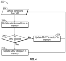
Fig. 4 , an exemplary schematic of thecontinuous evaluation loop 200 is illustrated. As previously described herein, thecontinuous evaluation loop 200 may be executed continuously, for example, byprocessor 148, at predetermined discrete time intervals (e.g., about every 20 milliseconds to about every 1 second, or more than 1 second or less than 20 milliseconds) while thematerial handling vehicle 100 is in operation (e.g., while thematerial handling vehicle 100 is "ON", irrespective of the mode the vehicle is in). Thecontinuous evaluation loop 200 can start when thetravel request controller 144 receives vehicle condition data from thevehicle manager 134, as illustrated byinput block 202. In one non-limiting example, the vehicle condition data can be communicated from thevehicle manager 134 to thetravel request controller 144 via a process data object. In one non-limiting example, the vehicle condition data can include one or both of the steering angle and the vehicle speed of thematerial handling vehicle 100. For example, thesteer control system 136 can sense the steering angle of thematerial handling vehicle 100 and thetraction controller 138 can sense the speed of thematerial handling vehicle 100. The sensed steering angle and speed of thematerial handling vehicle 100 can be communicated to thevehicle manager 134, and thevehicle manager 134 can then communicate the vehicle condition data to thetravel request controller 144. - In another non-limiting example, the vehicle condition data communicated from the
vehicle manager 134 to thetravel request controller 144 can further include the current mode thematerial handling vehicle 100 is operating in (e.g., either the manual mode or the travel request mode). In another non-limiting example, the vehicle condition data can further include brake application status. For example, thevehicle manager 134 can communicate through thetraction controller 138 to determine a status of thebrake 140, and communicate that status to thetravel request controller 144. - At
step 204, thetravel request controller 144 can store the vehicle condition data (e.g., steering angle, vehicle speed, etc.) on thememory 146 in thetravel request controller 144. Atstep 206, thetravel request controller 144 may then determine a vehicle condition, such as a motion condition, of the material handling vehicle. For example, thetravel request controller 144 can determine if thematerial handling vehicle 100 is stopped. For example, thetravel request controller 144 may use the vehicle speed received from thevehicle manager 134 or the vehicle speed stored in thememory 146 and compare the vehicle speed to a threshold value defined for a stopped vehicle (e.g., approximately 0 mph) to determine the motion condition of thematerial handling vehicle 100. In one non-limiting example, the threshold value can be zero mph. If thetravel request controller 144 determines that the vehicle speed is greater than the threshold value, then thetravel request controller 144 stores (e.g., in the memory 146) that thematerial handling vehicle 100 is "IN MOTION" (or some other representative designation that may indicate that the vehicle is not stopped), as indicated bystep 208. Conversely, if thetravel request controller 144 determines that the vehicle speed is at or less than the threshold value, then thetravel request controller 144 stores that thematerial handling vehicle 100 is "STOPPED" (or some other representative designation that may indicate that the vehicle is stopped), as indicated bystep 210. - As previously noted, the
continuous evaluation loop 200 may run continuously at discrete time intervals, which can enable, for example, thememory 146 of thetravel request controller 144 to have recent and accurate vehicle condition data stored on thememory 146. In one non-limiting example, thecontinuous evaluation loop 200 can be executed by thetravel request controller 144 about every 20 milliseconds. In another non-limiting example, thecontinuous evaluation loop 200 can be executed about every second, any time period between 20 milliseconds and one second, or any time period more than 1 second or less than 20 milliseconds. One of ordinary skill in the art readily recognizes that the specific time period chosen can be application specific and is not intended to be limiting in any way. - As will be described in greater detail in the paragraphs to follow, the
travel request controller 144 can execute thecontinuous evaluation loop 200 such that thetravel request controller 144 can evaluate the most recent vehicle condition data stored in thememory 146 upon receiving a travel command or a stop command given by thetravel control function 124 or the I/O function 126 on theremote control device 122. In one non-limiting example, only the most recent vehicle condition data can be stored in thememory 146. For example, one data point can be stored and then continuously updated (e.g., overwritten) in thememory 146 as thecontinuous evaluation loop 200 is executed by thetravel request controller 144. In another non-limiting example, a history of the vehicle condition data can be stored in thememory 146. - Referring now to
Fig. 5 , amethod 300 of switching thematerial handling vehicle 100 from the manual mode to the travel request mode will be described. The process may start atstep 302, where a request to transition from the manual mode to the travel request mode may be initiated (e.g., via one of the methods previously described herein). Atstep 304, thetravel request controller 144 may then recall at least one of the most recent vehicle condition data stored on the memory 146 (e.g., the vehicle condition data that was updated on the previouscontinuous evaluation loop 200 execution) and determine if the stored vehicle conditions are appropriate for transitioning from the manual mode to the travel request mode. In that way, thetravel request controller 144 can use vehicle condition data and motion condition information that has been previously updated to determine if vehicle conditions are appropriate for transitioning modes. For example, thetravel request controller 144 can ensure that the most recent motion condition stored in thememory 146 is "STOPPED." In addition, in some non-limiting examples, thetravel request controller 144 can also check other aspects of thematerial handling vehicle 100 atstep 304. For example, thetravel request controller 144 can query thevehicle manager 134 to ensure that thematerial handling vehicle 100 is being operated in a manual mode. Thetravel request controller 144 can also check to ensure the I/O function 126 on theremote control device 122 is not currently being actuated by an operator. If thetravel request controller 144 determines that the vehicle conditions are not appropriate for transitioning from the manual mode to the travel request mode, the travel request controller takes no action and continues to evaluate the vehicle conditions (e.g., by executing the continuous evaluation loop 200). - Upon the
travel request controller 144 determining that the vehicle conditions are appropriate based on the previously stored vehicle condition data, thetravel request controller 144 may then send a signal to thevehicle manager 134 to request a transition from the manual mode to the travel request mode atstep 306. In response to the signal sent from thetravel request controller 144 to thevehicle manager 134, thevehicle manager 134 can then enable the material handling vehicle to switch to the travel request mode atstep 308. With thematerial handling vehicle 100 in the travel request mode, remote operation of thematerial handling vehicle 100 by the operator using theremote control device 122 is then enabled. For example, the operator can use theremote control device 122 to send signals to thetravel request controller 144, as previously described herein. Thetravel request controller 144 can then generate vehicle commands and then communicate those vehicle commands to thevehicle manager 134 for execution. - The
material handling vehicle 100 can be switched back to the manual mode from the travel request mode by the operator (e.g., by actuating theswitch 151, seeFig. 1 ). According to one non-limiting example, the material handling vehicle can be switched back to the manual mode from the travel request mode by thevehicle manager 134, if thevehicle manager 134 detects vehicle conditions that result in switching back to the manual mode. - Referring now to
Figs. 3 and6 , amethod 400 of remotely operating thematerial handling vehicle 100 using theremote control device 122 when thematerial handling vehicle 100 is in a travel request mode is illustrated. In the exemplary discussion to follow, the example of an order picking operation will be described, where an operator of thematerial handling vehicle 100 may desire to move in an aisle and along a rack within a warehouse from one picking location to the next picking location. One of ordinary skill in the art readily recognizes that this is just one example of operation and is not intended to be limiting in any way. - The
method 400 may begin atstep 402, where the operator can actuate one of thetravel control function 124 or the I/O function 126 on theremote control device 122, thus generating a first signal or a second signal, respectively. Atstep 404, thetransmitter 128 may wirelessly communicate the first and/or second signal to thetravel request controller 144 via thereceiver 130 in communication with thetransmitter 128. - If the operator actuates the
travel control function 124, thetravel request controller 144 may then recall at least one of the most recent vehicle condition data stored on the memory 146 (e.g., the vehicle condition data that was updated on the previous/most recentcontinuous evaluation loop 200 execution) atstep 406 and determine if the stored vehicle conditions are appropriate for executing the travel request issued by theremote control device 122. For example, thetravel request controller 144 can ensure that the most recent motion condition stored in thememory 146 is "STOPPED." In that way, thetravel request controller 144 uses vehicle condition data and motion condition information that has been previously updated when determining if vehicle conditions are appropriate for the travel/stop command. - At
step 408, upon determining that the vehicle conditions are appropriate based on the previously stored vehicle condition data, thetravel request controller 144 may then send a request (e.g., a vehicle command) to thevehicle manager 134 based on the received signal atstep 404. For example, if the operator actuates thetravel control function 124 on the remote control device 122 (e.g., by depressing thefirst button 125 on theremote control device 122, seeFig. 7 ), thetravel request controller 144 can send a travel command to thevehicle manager 134 to instruct thematerial handling vehicle 100 to move, or otherwise travel forward. According to another example, if the operator actuates the I/O function 126 on theremote control device 122, an unpair command is sent to thetravel request controller 144 to request that thematerial handling vehicle 100 be unpaired from theremote control device 122 and a stop command can be sent from thetravel request controller 144 to thevehicle manager 134 to instruct thematerial handling vehicle 100 to come to a stop. - In response to the received commands, the
vehicle manager 134 can communicate to thetraction controller 138 atstep 410 to operate thepower unit 142 to enable thematerial handling vehicle 100 to travel or stop (e.g., if a travel command or a stop command is received, respectively). For example, thematerial handling vehicle 100 may be at a first picking location within an aisle of a warehouse and the operator may desire thematerial handling vehicle 100 to travel to a second picking location within that aisle. The travel command executed by thevehicle manager 134 can enable the material handling vehicle to travel forward from the first picking location to the second picking location. - While the
material handling vehicle 100 is traveling, the travel request controller may monitor thesensor 150 to determine if thematerial handling vehicle 100 should steer or stop. In the case that thesensor 150 provides an indication that thematerial handling vehicle 100 should steer, thetravel request controller 144 can send a steer command to thevehicle manager 134 to request a steering maneuver. In response to the received steering command, thevehicle manager 134 can communicate to thesteer control system 136 to maneuver the material handling vehicle 100 (e.g., to steer thematerial handling vehicle 100 to travel alongside a rack structure). In the case that thesensor 150 provides an indication that thematerial handling vehicle 100 should stop, for example, in response to detecting an obstacle in a travel path of thematerial handling vehicle 100, the travel request controller can send a stop command to thevehicle manager 134 to request that thematerial handling vehicle 100 come to a stop. In response to the received stop command, thevehicle manager 134 can communicate to thetraction controller 138 to stop the material handling vehicle 100 (e.g., to stop thematerial handling vehicle 100 if thesensor 150 detects an obstacle in a travel path of the material handling vehicle 100). - For certain types of vehicles there are training requirements imposed by various government agencies, laws, rules and regulations. For example, the United States Department of Labor Occupational Safety and Health Administration (OSHA) imposes a duty on employers to train and supervise operators of various types of material handling vehicles. Recertification every three years is also required. In certain instances, refresher training in relevant topics shall be provided to the operator when required. In all instances, the operator remains in control of the material handling vehicle during performance of any actions. Further, a warehouse manager remains in control of the fleet of material handling vehicles within the warehouse environment. The training of operators and supervision to be provided by warehouse managers requires among other things proper operational practices including among other things that an operator remain in control of the material handling vehicle, pay attention to the operating environment, and always look in the direction of travel.
- Within this specification embodiments have been described in a way which enables a clear and concise specification to be written, but it is intended and will be appreciated that embodiments may be variously combined or separated without parting from the invention. For example, it will be appreciated that all preferred features described herein are applicable to all aspects of the invention described herein.
- Thus, while the invention has been described in connection with particular embodiments and examples, the invention is not necessarily so limited, and that numerous other embodiments, examples, uses, modifications and departures from the embodiments, examples and uses are intended to be encompassed by the claims attached hereto.
- Various features and advantages of the invention are set forth in the following claims.
Claims (10)
- A system (120) for a remotely controllable material handling vehicle (100) switchable between a manual mode and a travel request mode, the system (120) comprising:a controller (144) comprising a processor (148) and a memory (146), wherein vehicle condition data previously evaluated by the controller (144) is stored in the memory (146);a remote control device (122) in communication with the controller (144), wherein a travel control function on the remote control device (122) is configured to provide a travel request to the controller (144) to cause the material handling vehicle (100) to move forward when the material handling vehicle (100) is in the travel request mode;the controller (144) configured to:receive the travel request;characterized in that,upon receiving the travel request, recall at least one vehicle condition data stored in the memory (146) that was evaluated previous to receiving the travel request to determine if the at least one vehicle condition is appropriate for moving the material handling vehicle (100) forward;based on the at least one vehicle condition data stored in the memory (146), command the material handling vehicle (100) to move forward; andprevious to receiving the travel request, execute a continuous evaluation loop (200) at predetermined discrete time intervals, wherein the continuous evaluation loop (200) includes:receiving the vehicle condition data;storing the vehicle condition data in the memory (146);evaluating the vehicle condition data to determine a motion condition of the material handling vehicle (100); andstoring the motion condition in the memory (146).
- The system (120) of claim 1, wherein the vehicle condition data is received via a process data object.
- The system (120) of claim 1 or claim 2, wherein the predetermined discrete time intervals are between about 20 milliseconds and about 1 second.
- The system (120) of any of the claims 1-3, wherein the controller (144) overwrites the previous vehicle condition data upon executing each continuous evaluation loop (200).
- The system (120) of any of the claims 1-4, wherein the vehicle condition data includes at least a vehicle speed of the material handling vehicle (100).
- The system (120) of claim 5, wherein the determination of the motion condition includes comparing the vehicle speed to a predetermined threshold value.
- The system (120) of claim 6, wherein the predetermined threshold value is zero mph.
- The system (120) of any of the claims 5 to 7, wherein if the vehicle speed is greater than the predetermined threshold value, the controller (144) determines that the material handling vehicle (100) is moving; and
wherein if the vehicle speed is less than the predetermined threshold value, the controller (144) determines that the material handling vehicle (100) is stopped. - A method for remotely operating a material handling vehicle (100) in a travel request mode, the method comprising:receiving a travel request from a remote control device (122) in communication with the material handling vehicle (100);characterized in,upon receiving the travel request, recalling at least one vehicle condition that was evaluated previous to receiving the travel request to determine if the at least one vehicle condition is appropriate for moving the material handling vehicle (100) forward;upon the determination that the at least one vehicle condition is appropriate, commanding the material handling vehicle (100) to move forward; andprevious to receiving the travel request, executing a continuous evaluation loop (200) at predetermined discrete time intervals, wherein the continuous evaluation loop includes:receiving vehicle condition data;storing the vehicle condition data in a memory (146);evaluating the vehicle condition data to determine the at least one vehicle condition of the material handling vehicle (100); andstoring the at least one vehicle condition in the memory (146).
- The method of claim 9, further comprising overwriting the previous vehicle condition data upon executing each continuous evaluation loop (200).
Applications Claiming Priority (1)
| Application Number | Priority Date | Filing Date | Title |
|---|---|---|---|
| US202062986299P | 2020-03-06 | 2020-03-06 |
Publications (3)
| Publication Number | Publication Date |
|---|---|
| EP3876064A1 EP3876064A1 (en) | 2021-09-08 |
| EP3876064C0 EP3876064C0 (en) | 2023-07-26 |
| EP3876064B1 true EP3876064B1 (en) | 2023-07-26 |
Family
ID=74859353
Family Applications (1)
| Application Number | Title | Priority Date | Filing Date |
|---|---|---|---|
| EP21161049.8A Active EP3876064B1 (en) | 2020-03-06 | 2021-03-05 | System and control method for a remotely controllable material handling vehicle |
Country Status (6)
| Country | Link |
|---|---|
| US (2) | US12410045B2 (en) |
| EP (1) | EP3876064B1 (en) |
| CN (1) | CN113433844A (en) |
| AU (1) | AU2021201427A1 (en) |
| CA (1) | CA3111413A1 (en) |
| MX (1) | MX2021002621A (en) |
Families Citing this family (6)
| Publication number | Priority date | Publication date | Assignee | Title |
|---|---|---|---|---|
| US11827503B2 (en) | 2020-03-18 | 2023-11-28 | Crown Equipment Corporation | Adaptive acceleration for materials handling vehicle |
| WO2022098402A1 (en) | 2020-11-03 | 2022-05-12 | Crown Equipment Corporation | Adaptive acceleration for materials handling vehicle |
| EP4295596B1 (en) * | 2021-02-19 | 2025-11-05 | Crown Equipment Corporation | Power savings for remote control device |
| US20230303373A1 (en) * | 2022-03-25 | 2023-09-28 | Logistics and Supply Chain MultiTech R&D Centre Limited | Teleoperated material handling system and material handling vehicle |
| CN116339339A (en) * | 2023-03-31 | 2023-06-27 | 奇瑞新能源汽车股份有限公司 | A control method and system for self-propelled vehicles on an automobile assembly line |
| CN119479108B (en) * | 2025-01-09 | 2025-03-21 | 思翼科技(深圳)有限公司 | Processing method of UAV power system data based on MCU external Flash memory |
Family Cites Families (22)
| Publication number | Priority date | Publication date | Assignee | Title |
|---|---|---|---|---|
| DE4014561A1 (en) * | 1990-05-04 | 1991-11-07 | Teves Gmbh Alfred | CONTROL SYSTEM FOR MOTOR VEHICLES |
| JP3054488B2 (en) * | 1992-02-28 | 2000-06-19 | 三洋電機株式会社 | Riding golf cart |
| DE19613386A1 (en) | 1996-04-03 | 1997-10-09 | Fiat Om Carrelli Elevatori | Industrial truck, which can be operated either manually or automatically |
| US6606550B1 (en) * | 2000-03-28 | 2003-08-12 | Robert Bosch Gmbh | Device for controlling an internal combustion engine |
| US7130729B2 (en) * | 2004-07-26 | 2006-10-31 | General Motors Corporation | Adaptive compensation of rear-wheel steering control using vehicle dynamics parameter estimation |
| US8970363B2 (en) * | 2006-09-14 | 2015-03-03 | Crown Equipment Corporation | Wrist/arm/hand mounted device for remotely controlling a materials handling vehicle |
| CA2860745C (en) * | 2006-09-14 | 2016-03-08 | Crown Equipment Corporation | Associating a transmitter and a receiver in a supplemental remote control system for materials handling vehicles |
| US9122276B2 (en) * | 2006-09-14 | 2015-09-01 | Crown Equipment Corporation | Wearable wireless remote control device for use with a materials handling vehicle |
| US8195366B2 (en) * | 2007-09-13 | 2012-06-05 | The Raymond Corporation | Control system for a pallet truck |
| WO2009117069A2 (en) * | 2008-03-17 | 2009-09-24 | Surgivision, Inc. | Low profile medical devices with internal drive shafts that cooperate with releasably engageable drive tools and related methods |
| US8433469B2 (en) * | 2011-03-18 | 2013-04-30 | The Raymond Corporation | Communication technique by which an autonomous guidance system controls an industrial vehicle |
| TW201501082A (en) * | 2013-06-27 | 2015-01-01 | 鴻海精密工業股份有限公司 | Vehicle trajectory simulation system and method |
| JP6732129B2 (en) * | 2016-11-30 | 2020-07-29 | ニッサン ノース アメリカ,インク | Remote control of autonomous vehicles to deal with problem situations |
| FR3068344B1 (en) | 2017-06-29 | 2019-08-23 | Compagnie Generale Des Etablissements Michelin | SYSTEM FOR CONTROLLING A FORKLIFT WITH AUTONOMOUS FORK, AND METHOD FOR CONTROLLING SUCH A TROLLEY. |
| FR3068345B1 (en) | 2017-06-29 | 2019-08-23 | Compagnie Generale Des Etablissements Michelin | SYSTEM FOR CONTROLLING A FORKLIFT FORK WITH MULTIPLE OPERATING MODES |
| JP6753385B2 (en) | 2017-10-23 | 2020-09-09 | 株式会社豊田自動織機 | Remote control system for industrial vehicles, remote control device, remote control program for industrial vehicles, and remote control method for industrial vehicles |
| US20200135033A1 (en) * | 2018-10-29 | 2020-04-30 | Peloton Technology, Inc. | Systems and methods for managing platoons |
| AU2020202306B2 (en) | 2019-04-02 | 2025-05-15 | The Raymond Corporation | Systems and methods for an arbitration controller to arbitrate multiple automation requests on a material handling device |
| US12259724B2 (en) | 2019-08-27 | 2025-03-25 | Crown Equipment Corporation | Adaptive acceleration for materials handling vehicle |
| EP4103969B8 (en) | 2020-02-12 | 2026-01-14 | Crown Equipment Corporation | Automating control of an industrial vehicle |
| CA3163133C (en) | 2020-02-21 | 2025-05-27 | Crown Equipment Corporation | POSITIONING ASSISTANCE SYSTEM FOR A MATERIAL HANDLING VEHICLE |
| US11827503B2 (en) | 2020-03-18 | 2023-11-28 | Crown Equipment Corporation | Adaptive acceleration for materials handling vehicle |
-
2021
- 2021-03-04 AU AU2021201427A patent/AU2021201427A1/en active Pending
- 2021-03-05 US US17/193,762 patent/US12410045B2/en active Active
- 2021-03-05 CA CA3111413A patent/CA3111413A1/en active Pending
- 2021-03-05 MX MX2021002621A patent/MX2021002621A/en unknown
- 2021-03-05 EP EP21161049.8A patent/EP3876064B1/en active Active
- 2021-03-08 CN CN202110251818.0A patent/CN113433844A/en active Pending
-
2025
- 2025-09-04 US US19/319,528 patent/US20260001750A1/en active Pending
Also Published As
| Publication number | Publication date |
|---|---|
| US20210276844A1 (en) | 2021-09-09 |
| US12410045B2 (en) | 2025-09-09 |
| EP3876064C0 (en) | 2023-07-26 |
| EP3876064A1 (en) | 2021-09-08 |
| US20260001750A1 (en) | 2026-01-01 |
| MX2021002621A (en) | 2022-07-11 |
| AU2021201427A1 (en) | 2021-09-23 |
| CA3111413A1 (en) | 2021-09-06 |
| CN113433844A (en) | 2021-09-24 |
Similar Documents
| Publication | Publication Date | Title |
|---|---|---|
| EP3876064B1 (en) | System and control method for a remotely controllable material handling vehicle | |
| US12448265B2 (en) | Systems and methods for control of a remotely controllable material handling vehicle | |
| US9207673B2 (en) | Finger-mounted apparatus for remotely controlling a materials handling vehicle | |
| KR101726209B1 (en) | Apparatus for remotely controlling a materials handling vehicle | |
| JP2019507974A (en) | Wireless capability and display for vehicle / trailer unit collision warning | |
| EP2631731A2 (en) | Improved robotic work tool | |
| EP2136275A1 (en) | Automatic driving system for automatically driving a motor vehicle along predefined paths | |
| JP4453683B2 (en) | Remote control device | |
| HK40056930A (en) | Systems and methods for evaluation of vehicle parameters of a remotely controllable material handling vehicle | |
| HK40061813A (en) | Systems and methods for control of a remotely controllable material handling vehicle | |
| EP4369132B1 (en) | Material handling vehicle mode transition systems and methods | |
| GB2102160A (en) | Control device for driverless guided vehicle | |
| HK40108748A (en) | Material handling vehicle mode transition systems and methods | |
| JPH05197427A (en) | Unmanned running vehicle | |
| JP2000305627A (en) | Golf cart |
Legal Events
| Date | Code | Title | Description |
|---|---|---|---|
| PUAI | Public reference made under article 153(3) epc to a published international application that has entered the european phase |
Free format text: ORIGINAL CODE: 0009012 |
|
| STAA | Information on the status of an ep patent application or granted ep patent |
Free format text: STATUS: THE APPLICATION HAS BEEN PUBLISHED |
|
| AK | Designated contracting states |
Kind code of ref document: A1 Designated state(s): AL AT BE BG CH CY CZ DE DK EE ES FI FR GB GR HR HU IE IS IT LI LT LU LV MC MK MT NL NO PL PT RO RS SE SI SK SM TR |
|
| STAA | Information on the status of an ep patent application or granted ep patent |
Free format text: STATUS: REQUEST FOR EXAMINATION WAS MADE |
|
| 17P | Request for examination filed |
Effective date: 20220308 |
|
| RBV | Designated contracting states (corrected) |
Designated state(s): AL AT BE BG CH CY CZ DE DK EE ES FI FR GB GR HR HU IE IS IT LI LT LU LV MC MK MT NL NO PL PT RO RS SE SI SK SM TR |
|
| STAA | Information on the status of an ep patent application or granted ep patent |
Free format text: STATUS: EXAMINATION IS IN PROGRESS |
|
| 17Q | First examination report despatched |
Effective date: 20220527 |
|
| GRAP | Despatch of communication of intention to grant a patent |
Free format text: ORIGINAL CODE: EPIDOSNIGR1 |
|
| STAA | Information on the status of an ep patent application or granted ep patent |
Free format text: STATUS: GRANT OF PATENT IS INTENDED |
|
| INTG | Intention to grant announced |
Effective date: 20230224 |
|
| GRAS | Grant fee paid |
Free format text: ORIGINAL CODE: EPIDOSNIGR3 |
|
| GRAA | (expected) grant |
Free format text: ORIGINAL CODE: 0009210 |
|
| STAA | Information on the status of an ep patent application or granted ep patent |
Free format text: STATUS: THE PATENT HAS BEEN GRANTED |
|
| AK | Designated contracting states |
Kind code of ref document: B1 Designated state(s): AL AT BE BG CH CY CZ DE DK EE ES FI FR GB GR HR HU IE IS IT LI LT LU LV MC MK MT NL NO PL PT RO RS SE SI SK SM TR |
|
| RAP3 | Party data changed (applicant data changed or rights of an application transferred) |
Owner name: THE RAYMOND CORPORATION |
|
| REG | Reference to a national code |
Ref country code: CH Ref legal event code: EP |
|
| REG | Reference to a national code |
Ref country code: IE Ref legal event code: FG4D |
|
| REG | Reference to a national code |
Ref country code: DE Ref legal event code: R096 Ref document number: 602021003691 Country of ref document: DE |
|
| U01 | Request for unitary effect filed |
Effective date: 20230825 |
|
| U07 | Unitary effect registered |
Designated state(s): AT BE BG DE DK EE FI FR IT LT LU LV MT NL PT SE SI Effective date: 20230829 |
|
| REG | Reference to a national code |
Ref country code: LT Ref legal event code: MG9D |
|
| PG25 | Lapsed in a contracting state [announced via postgrant information from national office to epo] |
Ref country code: GR Free format text: LAPSE BECAUSE OF FAILURE TO SUBMIT A TRANSLATION OF THE DESCRIPTION OR TO PAY THE FEE WITHIN THE PRESCRIBED TIME-LIMIT Effective date: 20231027 |
|
| PG25 | Lapsed in a contracting state [announced via postgrant information from national office to epo] |
Ref country code: IS Free format text: LAPSE BECAUSE OF FAILURE TO SUBMIT A TRANSLATION OF THE DESCRIPTION OR TO PAY THE FEE WITHIN THE PRESCRIBED TIME-LIMIT Effective date: 20231126 |
|
| PG25 | Lapsed in a contracting state [announced via postgrant information from national office to epo] |
Ref country code: RS Free format text: LAPSE BECAUSE OF FAILURE TO SUBMIT A TRANSLATION OF THE DESCRIPTION OR TO PAY THE FEE WITHIN THE PRESCRIBED TIME-LIMIT Effective date: 20230726 Ref country code: NO Free format text: LAPSE BECAUSE OF FAILURE TO SUBMIT A TRANSLATION OF THE DESCRIPTION OR TO PAY THE FEE WITHIN THE PRESCRIBED TIME-LIMIT Effective date: 20231026 Ref country code: IS Free format text: LAPSE BECAUSE OF FAILURE TO SUBMIT A TRANSLATION OF THE DESCRIPTION OR TO PAY THE FEE WITHIN THE PRESCRIBED TIME-LIMIT Effective date: 20231126 Ref country code: HR Free format text: LAPSE BECAUSE OF FAILURE TO SUBMIT A TRANSLATION OF THE DESCRIPTION OR TO PAY THE FEE WITHIN THE PRESCRIBED TIME-LIMIT Effective date: 20230726 Ref country code: GR Free format text: LAPSE BECAUSE OF FAILURE TO SUBMIT A TRANSLATION OF THE DESCRIPTION OR TO PAY THE FEE WITHIN THE PRESCRIBED TIME-LIMIT Effective date: 20231027 |
|
| PG25 | Lapsed in a contracting state [announced via postgrant information from national office to epo] |
Ref country code: PL Free format text: LAPSE BECAUSE OF FAILURE TO SUBMIT A TRANSLATION OF THE DESCRIPTION OR TO PAY THE FEE WITHIN THE PRESCRIBED TIME-LIMIT Effective date: 20230726 |
|
| U20 | Renewal fee for the european patent with unitary effect paid |
Year of fee payment: 4 Effective date: 20240207 |
|
| PG25 | Lapsed in a contracting state [announced via postgrant information from national office to epo] |
Ref country code: ES Free format text: LAPSE BECAUSE OF FAILURE TO SUBMIT A TRANSLATION OF THE DESCRIPTION OR TO PAY THE FEE WITHIN THE PRESCRIBED TIME-LIMIT Effective date: 20230726 |
|
| REG | Reference to a national code |
Ref country code: DE Ref legal event code: R097 Ref document number: 602021003691 Country of ref document: DE |
|
| PG25 | Lapsed in a contracting state [announced via postgrant information from national office to epo] |
Ref country code: SM Free format text: LAPSE BECAUSE OF FAILURE TO SUBMIT A TRANSLATION OF THE DESCRIPTION OR TO PAY THE FEE WITHIN THE PRESCRIBED TIME-LIMIT Effective date: 20230726 Ref country code: RO Free format text: LAPSE BECAUSE OF FAILURE TO SUBMIT A TRANSLATION OF THE DESCRIPTION OR TO PAY THE FEE WITHIN THE PRESCRIBED TIME-LIMIT Effective date: 20230726 Ref country code: ES Free format text: LAPSE BECAUSE OF FAILURE TO SUBMIT A TRANSLATION OF THE DESCRIPTION OR TO PAY THE FEE WITHIN THE PRESCRIBED TIME-LIMIT Effective date: 20230726 Ref country code: CZ Free format text: LAPSE BECAUSE OF FAILURE TO SUBMIT A TRANSLATION OF THE DESCRIPTION OR TO PAY THE FEE WITHIN THE PRESCRIBED TIME-LIMIT Effective date: 20230726 Ref country code: SK Free format text: LAPSE BECAUSE OF FAILURE TO SUBMIT A TRANSLATION OF THE DESCRIPTION OR TO PAY THE FEE WITHIN THE PRESCRIBED TIME-LIMIT Effective date: 20230726 |
|
| PLBE | No opposition filed within time limit |
Free format text: ORIGINAL CODE: 0009261 |
|
| STAA | Information on the status of an ep patent application or granted ep patent |
Free format text: STATUS: NO OPPOSITION FILED WITHIN TIME LIMIT |
|
| 26N | No opposition filed |
Effective date: 20240429 |
|
| REG | Reference to a national code |
Ref country code: CH Ref legal event code: PL |
|
| PG25 | Lapsed in a contracting state [announced via postgrant information from national office to epo] |
Ref country code: MC Free format text: LAPSE BECAUSE OF FAILURE TO SUBMIT A TRANSLATION OF THE DESCRIPTION OR TO PAY THE FEE WITHIN THE PRESCRIBED TIME-LIMIT Effective date: 20230726 |
|
| PG25 | Lapsed in a contracting state [announced via postgrant information from national office to epo] |
Ref country code: MC Free format text: LAPSE BECAUSE OF FAILURE TO SUBMIT A TRANSLATION OF THE DESCRIPTION OR TO PAY THE FEE WITHIN THE PRESCRIBED TIME-LIMIT Effective date: 20230726 |
|
| PG25 | Lapsed in a contracting state [announced via postgrant information from national office to epo] |
Ref country code: IE Free format text: LAPSE BECAUSE OF NON-PAYMENT OF DUE FEES Effective date: 20240305 |
|
| PG25 | Lapsed in a contracting state [announced via postgrant information from national office to epo] |
Ref country code: IE Free format text: LAPSE BECAUSE OF NON-PAYMENT OF DUE FEES Effective date: 20240305 Ref country code: CH Free format text: LAPSE BECAUSE OF NON-PAYMENT OF DUE FEES Effective date: 20240331 |
|
| U20 | Renewal fee for the european patent with unitary effect paid |
Year of fee payment: 5 Effective date: 20250205 |
|
| PG25 | Lapsed in a contracting state [announced via postgrant information from national office to epo] |
Ref country code: CY Free format text: LAPSE BECAUSE OF FAILURE TO SUBMIT A TRANSLATION OF THE DESCRIPTION OR TO PAY THE FEE WITHIN THE PRESCRIBED TIME-LIMIT; INVALID AB INITIO Effective date: 20210305 |
|
| PG25 | Lapsed in a contracting state [announced via postgrant information from national office to epo] |
Ref country code: HU Free format text: LAPSE BECAUSE OF FAILURE TO SUBMIT A TRANSLATION OF THE DESCRIPTION OR TO PAY THE FEE WITHIN THE PRESCRIBED TIME-LIMIT; INVALID AB INITIO Effective date: 20210305 |
|
| PG25 | Lapsed in a contracting state [announced via postgrant information from national office to epo] |
Ref country code: TR Free format text: LAPSE BECAUSE OF FAILURE TO SUBMIT A TRANSLATION OF THE DESCRIPTION OR TO PAY THE FEE WITHIN THE PRESCRIBED TIME-LIMIT Effective date: 20230726 |
|
| U20 | Renewal fee for the european patent with unitary effect paid |
Year of fee payment: 6 Effective date: 20260209 |
|
| PGFP | Annual fee paid to national office [announced via postgrant information from national office to epo] |
Ref country code: GB Payment date: 20260106 Year of fee payment: 6 |