EP3876039A1 - Moving mechanism and image forming apparatus - Google Patents
Moving mechanism and image forming apparatus Download PDFInfo
- Publication number
- EP3876039A1 EP3876039A1 EP21157605.3A EP21157605A EP3876039A1 EP 3876039 A1 EP3876039 A1 EP 3876039A1 EP 21157605 A EP21157605 A EP 21157605A EP 3876039 A1 EP3876039 A1 EP 3876039A1
- Authority
- EP
- European Patent Office
- Prior art keywords
- protrusion
- photoreceptor
- image forming
- stage
- terminal
- Prior art date
- Legal status (The legal status is an assumption and is not a legal conclusion. Google has not performed a legal analysis and makes no representation as to the accuracy of the status listed.)
- Granted
Links
Images









Classifications
-
- G—PHYSICS
- G03—PHOTOGRAPHY; CINEMATOGRAPHY; ANALOGOUS TECHNIQUES USING WAVES OTHER THAN OPTICAL WAVES; ELECTROGRAPHY; HOLOGRAPHY
- G03G—ELECTROGRAPHY; ELECTROPHOTOGRAPHY; MAGNETOGRAPHY
- G03G15/00—Apparatus for electrographic processes using a charge pattern
- G03G15/04—Apparatus for electrographic processes using a charge pattern for exposing, i.e. imagewise exposure by optically projecting the original image on a photoconductive recording material
- G03G15/043—Apparatus for electrographic processes using a charge pattern for exposing, i.e. imagewise exposure by optically projecting the original image on a photoconductive recording material with means for controlling illumination or exposure
-
- G—PHYSICS
- G03—PHOTOGRAPHY; CINEMATOGRAPHY; ANALOGOUS TECHNIQUES USING WAVES OTHER THAN OPTICAL WAVES; ELECTROGRAPHY; HOLOGRAPHY
- G03G—ELECTROGRAPHY; ELECTROPHOTOGRAPHY; MAGNETOGRAPHY
- G03G21/00—Arrangements not provided for by groups G03G13/00 - G03G19/00, e.g. cleaning, elimination of residual charge
- G03G21/16—Mechanical means for facilitating the maintenance of the apparatus, e.g. modular arrangements
- G03G21/1642—Mechanical means for facilitating the maintenance of the apparatus, e.g. modular arrangements for connecting the different parts of the apparatus
- G03G21/1647—Mechanical connection means
-
- G—PHYSICS
- G03—PHOTOGRAPHY; CINEMATOGRAPHY; ANALOGOUS TECHNIQUES USING WAVES OTHER THAN OPTICAL WAVES; ELECTROGRAPHY; HOLOGRAPHY
- G03G—ELECTROGRAPHY; ELECTROPHOTOGRAPHY; MAGNETOGRAPHY
- G03G15/00—Apparatus for electrographic processes using a charge pattern
- G03G15/04—Apparatus for electrographic processes using a charge pattern for exposing, i.e. imagewise exposure by optically projecting the original image on a photoconductive recording material
- G03G15/04036—Details of illuminating systems, e.g. lamps, reflectors
- G03G15/04045—Details of illuminating systems, e.g. lamps, reflectors for exposing image information provided otherwise than by directly projecting the original image onto the photoconductive recording material, e.g. digital copiers
- G03G15/04054—Details of illuminating systems, e.g. lamps, reflectors for exposing image information provided otherwise than by directly projecting the original image onto the photoconductive recording material, e.g. digital copiers by LED arrays
-
- G—PHYSICS
- G03—PHOTOGRAPHY; CINEMATOGRAPHY; ANALOGOUS TECHNIQUES USING WAVES OTHER THAN OPTICAL WAVES; ELECTROGRAPHY; HOLOGRAPHY
- G03G—ELECTROGRAPHY; ELECTROPHOTOGRAPHY; MAGNETOGRAPHY
- G03G21/00—Arrangements not provided for by groups G03G13/00 - G03G19/00, e.g. cleaning, elimination of residual charge
- G03G21/16—Mechanical means for facilitating the maintenance of the apparatus, e.g. modular arrangements
- G03G21/1661—Mechanical means for facilitating the maintenance of the apparatus, e.g. modular arrangements means for handling parts of the apparatus in the apparatus
- G03G21/1666—Mechanical means for facilitating the maintenance of the apparatus, e.g. modular arrangements means for handling parts of the apparatus in the apparatus for the exposure unit
-
- G—PHYSICS
- G03—PHOTOGRAPHY; CINEMATOGRAPHY; ANALOGOUS TECHNIQUES USING WAVES OTHER THAN OPTICAL WAVES; ELECTROGRAPHY; HOLOGRAPHY
- G03G—ELECTROGRAPHY; ELECTROPHOTOGRAPHY; MAGNETOGRAPHY
- G03G21/00—Arrangements not provided for by groups G03G13/00 - G03G19/00, e.g. cleaning, elimination of residual charge
- G03G21/16—Mechanical means for facilitating the maintenance of the apparatus, e.g. modular arrangements
- G03G21/1661—Mechanical means for facilitating the maintenance of the apparatus, e.g. modular arrangements means for handling parts of the apparatus in the apparatus
- G03G21/1671—Mechanical means for facilitating the maintenance of the apparatus, e.g. modular arrangements means for handling parts of the apparatus in the apparatus for the photosensitive element
-
- G—PHYSICS
- G03—PHOTOGRAPHY; CINEMATOGRAPHY; ANALOGOUS TECHNIQUES USING WAVES OTHER THAN OPTICAL WAVES; ELECTROGRAPHY; HOLOGRAPHY
- G03G—ELECTROGRAPHY; ELECTROPHOTOGRAPHY; MAGNETOGRAPHY
- G03G21/00—Arrangements not provided for by groups G03G13/00 - G03G19/00, e.g. cleaning, elimination of residual charge
- G03G21/16—Mechanical means for facilitating the maintenance of the apparatus, e.g. modular arrangements
- G03G21/1642—Mechanical means for facilitating the maintenance of the apparatus, e.g. modular arrangements for connecting the different parts of the apparatus
-
- G—PHYSICS
- G03—PHOTOGRAPHY; CINEMATOGRAPHY; ANALOGOUS TECHNIQUES USING WAVES OTHER THAN OPTICAL WAVES; ELECTROGRAPHY; HOLOGRAPHY
- G03G—ELECTROGRAPHY; ELECTROPHOTOGRAPHY; MAGNETOGRAPHY
- G03G2221/00—Processes not provided for by group G03G2215/00, e.g. cleaning or residual charge elimination
- G03G2221/16—Mechanical means for facilitating the maintenance of the apparatus, e.g. modular arrangements and complete machine concepts
- G03G2221/1636—Mechanical means for facilitating the maintenance of the apparatus, e.g. modular arrangements and complete machine concepts for the exposure unit
-
- G—PHYSICS
- G03—PHOTOGRAPHY; CINEMATOGRAPHY; ANALOGOUS TECHNIQUES USING WAVES OTHER THAN OPTICAL WAVES; ELECTROGRAPHY; HOLOGRAPHY
- G03G—ELECTROGRAPHY; ELECTROPHOTOGRAPHY; MAGNETOGRAPHY
- G03G2221/00—Processes not provided for by group G03G2215/00, e.g. cleaning or residual charge elimination
- G03G2221/16—Mechanical means for facilitating the maintenance of the apparatus, e.g. modular arrangements and complete machine concepts
- G03G2221/1651—Mechanical means for facilitating the maintenance of the apparatus, e.g. modular arrangements and complete machine concepts for connecting the different parts
- G03G2221/1654—Locks and means for positioning or alignment
Definitions
- Embodiments described herein relate generally to a moving mechanism and an image forming apparatus.
- a line-type light source such as an LED array may be used as an exposure light source of the image forming apparatus.
- the line-type light source is held in an exposure device.
- Light emitted from the line-type light source is focused on a line by a lens included in the exposure device.
- the exposure device is supported by a moving mechanism which advances toward and retreats from a photoreceptor unit including a photoreceptor.
- the moving mechanism moves the exposure device between an abutment position where the exposure device abuts on the photoreceptor unit and a separation position where the exposure device is separated from the photoreceptor unit.
- the exposure device is positioned with respect to the photoreceptor so that the emitted light is focused at an exposure position on a surface of a photoreceptor drum.
- One of the objects of the present invention is to improve prior art techniques and overcome at least some of the prior art problems as for instance above illustrated.
- an image forming apparatus comprising: a photoreceptor component comprising a photoreceptor configured to carry an electrostatic latent image; a first terminal configured to be supported by the photoreceptor component; a stage comprising a second terminal that fits with the first terminal and configured to regulate a relative movement in a first direction with the photoreceptor and to move from a first position closer to the photoreceptor to a second position farther from the photoreceptor in a second direction opposite to the first position so that the second terminal fits with the first terminal; a first protrusion that protrudes from a base portion provided on the stage in a direction intersecting the second direction; a second protrusion that protrudes in a direction intersecting the first direction from the first protrusion at a position separated from the base portion in the first direction; a slider configured to move in a third direction that intersects the second direction and the first direction, in which a thickness of a first position regulation portion in the first direction that regulates
- the thickness of the second position regulation portion in the first direction is a size that fits in a gap between the base portion and the second protrusion.
- the guide portion is inclined in a direction that diagonally intersects the second direction when viewed from the first direction.
- the first terminal comprises a shaft member long in the second direction
- the second terminal comprises a tubular portion configured to fit to the first terminal at least in the first direction and a curved portion whose diameter gradually increases from an end of the tubular portion in the second direction toward the second direction.
- the photoreceptor is a photoreceptor drum.
- the second terminal fits with the first terminal in a concave-convex manner.
- the third direction intersects the second direction and the first direction in a perpendicular manner.
- the first protrusion comprises a columnar portion and a tapered portion.
- the second protrusion comprises a columnar portion and a tapered portion.
- the slider has a cross section having a substantially trapezoidal shape.
- a moving mechanism for an image forming apparatus which includes a photoreceptor configured to carry an electrostatic latent image, a first terminal, and an exposure device that emits light to draw an electrostatic latent image on the photoreceptor, the moving mechanism comprising: a stage comprising a second terminal that fits with the first terminal and configured to regulate a relative movement in a first direction with the photoreceptor, to move from a first position closer to the photoreceptor to a second position farther from the photoreceptor in a second direction opposite the first position so that the second terminal fits with the first terminal, and to support the exposure device; a first protrusion that protrudes from a base portion provided on the stage in a direction intersecting the second direction; a second protrusion that protrudes in a direction intersecting the first direction from the first protrusion at a position separated from the base portion in the first direction; and a slider configured to move in a third direction that intersects the second direction and the first direction, in
- the thickness of the second position regulation portion in the first direction is a size that fits in a gap between the base portion and the second protrusion.
- the guide portion is inclined in a direction that diagonally intersects the second direction when viewed from the first direction.
- the first terminal comprises a shaft member long in the second direction
- the second terminal comprises a tubular portion configured to fit to the first terminal at least in the first direction and a curved portion whose diameter gradually increases from an end of the tubular portion in the second direction toward the second direction.
- the photoreceptor is a photoreceptor drum.
- the second terminal fits with the first terminal in a concave-convex manner.
- the third direction intersects the second direction and the first direction in a perpendicular manner.
- the first protrusion comprises a columnar portion and a tapered portion.
- the second protrusion comprises a columnar portion and a tapered portion.
- the slider has a cross section having a substantially trapezoidal shape.
- Embodiments provide a moving mechanism and an image forming apparatus that facilitates positioning of a stage and an operation of the stage.
- an image forming apparatus including a photoreceptor unit, a first terminal, a stage, a first protrusion, a second protrusion, a slider, and an exposure device.
- the photoreceptor unit is configured to include a photoreceptor for carrying an electrostatic latent image.
- the first terminal is configured to be supported by the photoreceptor unit.
- the stage is configured to include a second terminal that fits with the first terminal and regulates a relative movement in a first direction with the photoreceptor.
- the stage is configured to be able to move from a first position closer to the photoreceptor to a second position farther from the photoreceptor in a second direction than the first position so that the second terminal is fitted to the first terminal.
- the first protrusion is configured to protrude from a base portion provided on the stage in a direction intersecting the second direction.
- the second protrusion is configured to protrude in a direction intersecting the first direction from the first protrusion at a position separated from the base portion in the first direction.
- the slider is configured to move in a third direction that intersects the second direction and the first direction.
- the slider is configured to include a first position regulation portion and a second position regulation portion at positions separated from each other in the third direction.
- the first position regulation portion regulates a position of the first protrusion in the second direction when the stage is in the first position.
- the second position regulation portion abuts on the first protrusion when the stage is in the second position.
- a thickness of the first position regulation portion in the first direction is thinner than a thickness of the second position regulation portion in the first direction.
- the slider is configured to slide with the first protrusion between the base portion and the second protrusion and include a guide portion which is long in the third direction between the second position regulation portion and the first position regulation portion.
- the exposure device is configured to be supported by the stage and to emit light to draw an electrostatic latent image on the photoreceptor.
- FIG. 1 is a schematic cross-sectional view illustrating an overall configuration example of the image forming apparatus.
- an image forming apparatus 100 of the present embodiment includes a control panel 1, a scanner unit 2, a printer unit 3, a sheet supply unit 4, a conveyance unit 5, a manual feed unit 10, and a control unit 6.
- an X1 direction, an X2 direction, a Y1 direction, a Y2 direction, a Z1 direction, and a Z2 direction illustrated in the figure may be used.
- the X1 direction is a direction from left to right when standing in front of the image forming apparatus 100 (front side of the paper in FIG. 1 ).
- the X2 direction is opposite to the X1 direction.
- the Y1 direction is a direction from the back surface to the front surface of the image forming apparatus 100.
- the Y2 direction is opposite to the Y1 direction.
- the Z1 direction is a vertically upward direction.
- the Z2 direction is a vertically downward direction.
- the X1 (Y1, Z1) direction and the X2 (Y2, Z2) direction are not intended to be distinguished from each other, or when both directions are included, the X1 (Y1, Z1) direction and the X2 (Y2, Z2) direction are simply described as the X (Y, Z) direction.
- a plane having a normal line in the X direction is referred to as a YZ plane
- a plane having a normal line in the Y direction is referred to as a ZX plane
- a plane having a normal line in the Z direction is referred to as an XY plane.
- the ZX plane is a plane parallel to a conveyance direction of a sheet S in the image forming apparatus 100.
- the XY plane is a horizontal plane.
- each member of the image forming apparatus 100 will be described based on a state of being disposed in the image forming apparatus 100.
- the control panel 1 operates the image forming apparatus 100 by being operated by a user.
- the scanner unit 2 reads image information of an object to be copied based on brightness and darkness of light.
- the scanner unit 2 outputs the read image information to the printer unit 3.
- the printer unit 3 forms an image on the sheet S based on the image information from the scanner unit 2 or the outside.
- the printer unit 3 forms an output image (toner image) with a developer containing toner.
- the printer unit 3 transfers the toner image onto a surface of the sheet S.
- the printer unit 3 applies heat and pressure to the toner image on the surface of the sheet S to fix the toner image on the sheet S.
- the sheet supply unit 4 supplies the sheet S one by one to the printer unit 3 according to the timing when the printer unit 3 forms the toner image.
- the sheet supply unit 4 includes a paper feed cassette 20 and a cassette paper feed unit 21.
- the paper feed cassette 20 accommodates sheets S of various sizes.
- the cassette paper feed unit 21 is above an end portion of the paper feed cassette 20 in the X1 direction.
- the cassette paper feed unit 21 includes a pickup roller 22B, a paper feed roller 22A, and a separation roller 22C.
- the pickup roller 22B conveys the sheet S required for image formation from the paper feed cassette 20 to a nip portion between the paper feed roller 22A and the separation roller 22C.
- the paper feed roller 22A conveys the sheet S conveyed to the nip portion to the conveyance unit 5.
- the separation roller 22C separates one sheet S when a plurality of sheets S are conveyed.
- the conveyance unit 5 includes registration rollers 24.
- the registration rollers 24 align a tip of the sheet S fed by the paper feed roller 22A at a nip NP.
- the registration rollers 24 convey the sheet S according to the timing when the printer unit 3 transfers the toner image to the sheet S.
- the registration rollers 24 convey the sheet S toward a transfer unit 28.
- the printer unit 3 includes image forming units 25Y, 25M, 25C, and 25K, exposure units 26, an intermediate transfer belt 27, the transfer unit 28, a fixing device 29, and a transfer belt cleaning unit 35.
- the image forming units 25Y, 25M, 25C, and 25K are arranged in this order in the X1 direction.
- Each of the image forming units 25Y, 25M, 25C, and 25K forms a toner image to be transferred to the sheet S on the intermediate transfer belt 27.
- the image forming units 25Y, 25M, 25C, and 25K each include a photoreceptor drum 7.
- the photoreceptor drum 7 includes a photosensitive layer on a surface thereof, and is an example of a photoreceptor for carrying an electrostatic latent image.
- the image forming units 25Y, 25M, 25C, and 25K form a yellow, magenta, cyan, and black toner image on the photoreceptor drums 7, respectively, by developing the electrostatic latent image of each photoreceptor drum 7.
- a charger, the exposure unit 26, a developing device 8, a primary transfer roller, a cleaning unit, and an electric neutralizer are disposed around each photoreceptor drum 7.
- the primary transfer roller faces the photoreceptor drum 7.
- the intermediate transfer belt 27 is sandwiched between the primary transfer roller and the photoreceptor drum 7.
- Toner cartridges 33Y, 33M, 33C, and 33K are disposed above the image forming units 25Y, 25M, 25C, and 25K.
- the toner cartridges 33Y, 33M, 33C, and 33K contain yellow, magenta, cyan, and black toners, respectively.
- the toners of the toner cartridges 33Y, 33M, 33C, and 33K are respectively supplied to the image forming units 25Y, 25M, 25C, and 25K by a toner supply tube (not illustrated).
- Each exposure unit 26 irradiates the surface of each charged photoreceptor drum 7 with light. Light emission is controlled based on the image information.
- Each exposure unit 26 includes a light source in which a plurality of light emitting elements are arranged in the Y1 direction. In the example illustrated in FIG. 1 , each exposure unit 26 is disposed below each of the image forming units 25Y, 25M, 25C, and 25K.
- Image information corresponding to yellow, magenta, cyan, and black is supplied to the exposure units 26, respectively.
- Each exposure unit 26 forms an electrostatic latent image based on image information on the surface of each photoreceptor drum 7.
- FIG. 2 is a schematic perspective view illustrating the exposure units and a base portion in the image forming apparatus.
- the exposure unit 26 is disposed on the base portion 11 provided in the printer unit 3.
- the base portion 11 has four recesses 11a on which four exposure units 26 can be disposed.
- Each recess 11a is a groove long in the Y direction.
- Each recess 11a positions the bottom and sides of each exposure unit 26.
- the intermediate transfer belt 27 is an endless belt. Tension is applied to the intermediate transfer belt 27 by a plurality of rollers that are abutted on an inner peripheral surface thereof.
- the intermediate transfer belt 27 is stretched to be flat.
- the inner peripheral surface of the intermediate transfer belt 27 abuts on a support roller 28a at the most distant position in the X1 direction in a stretched direction.
- the inner peripheral surface of the intermediate transfer belt 27 abuts on a transfer belt roller 32 at the most distant position in the X2 direction in the stretched direction.
- the support roller 28a forms a part of the transfer unit 28.
- the support roller 28a guides the intermediate transfer belt 27 to a secondary transfer position.
- the transfer belt roller 32 guides the intermediate transfer belt 27 to a cleaning position.
- the image forming units 25Y, 25M, 25C, and 25K excluding the primary transfer roller are disposed in this order in the X1 direction.
- the image forming units 25Y, 25M, 25C, and 25K are disposed to be spaced apart from each other in a region between the transfer belt roller 32 and the support roller 28a.
- a transfer bias is applied to each of the primary transfer rollers of the image forming portions 25Y, 25M, 25C, and 25K when the toner image reaches the primary transfer position.
- Each primary transfer roller primarily transfers the toner image on the surface of each photoreceptor drum 7 onto the intermediate transfer belt 27.
- the transfer unit 28 is disposed at a position adjacent to the image forming unit 25K.
- the transfer unit 28 includes the support roller 28a and a secondary transfer roller 28b.
- the intermediate transfer belt 27 is sandwiched between the secondary transfer roller 28b and the support roller 28a. A position where the secondary transfer roller 28b and the intermediate hand transfer belt 27 abut on each other is the secondary transfer position.
- the transfer unit 28 transfers a charged toner image on the intermediate transfer belt 27 onto the surface of the sheet S at the secondary transfer position.
- the transfer unit 28 applies the transfer bias to the secondary transfer position.
- the transfer unit 28 transfers the toner image on the intermediate transfer belt 27 onto the sheet S by the transfer bias.
- the fixing device 29 applies heat and pressure to the sheet S.
- the fixing device 29 fixes the toner image transferred onto the sheet S by the heat and pressure.
- the fixing device 29 is disposed above the transfer unit 28.
- the transfer belt cleaning unit 35 faces the transfer belt roller 32.
- the transfer belt cleaning unit 35 sandwiches the intermediate transfer belt 27.
- the transfer belt cleaning unit 35 scrapes off the toner on the surface of the intermediate transfer belt 27.
- conveyance paths 30A and 30B for conveying the sheet S from a lower side to an upper side are formed in this order, respectively.
- Each of the conveyance paths 30A, 30B, and 30C includes a conveyance guide portion and a conveyance roller that face each other with the sheet S in between.
- the manual feed unit 10 supplies the sheet S on which the image is formed to the printer unit 3. If a manual feed tray 13 is used, the manual feed tray 13 is opened by being rotated clockwise as illustrated by the solid line. Sheets S of various sizes can be placed on the opened manual feed tray 13.
- the manual feed unit 10 includes a pickup roller, a paper feed roller, and a separation roller similar to those of the sheet supply unit 4.
- the control unit 6 controls the entire image forming apparatus 100 and each apparatus portion.
- the control unit 6 controls the control panel 1, the scanner unit 2, the printer unit 3, the sheet supply unit 4, the conveyance unit 5, and the manual feed unit 10 to convey the sheet S and form an image on the sheet S.
- control unit 6 As a device configuration of the control unit 6, for example, a processor such as a central processing unit (CPU) may be used.
- CPU central processing unit
- each exposure unit 26 The detailed configuration of each exposure unit 26 will be described.
- the configurations of the exposure units 26 are common to each other.
- the image forming units 25Y, 25M, 25C, and 25K disposed above the exposure units 26 are not distinguished from each other, the image forming units 25Y, 25M, 25C, and 25K are referred to as an image forming unit 25.
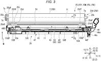
- FIG. 3 is a schematic side view illustrating the photoreceptor, the exposure unit, and the moving mechanism in the image forming apparatus of the embodiment.
- FIG. 4 is a schematic perspective view of the case accommodating the photoreceptor in the image forming apparatus.
- the image forming unit 25 includes a photoreceptor unit 25D including the photoreceptor drum 7 and a case 25A accommodating the photoreceptor drum 7.
- the exposure unit 26 in the image forming unit 25 includes an exposure device 43 and a moving mechanism 47.
- the exposure device 43 emits light to draw an electrostatic latent image on the photoreceptor drum 7.
- the moving mechanism 47 moves the exposure device 43 in the second direction between a second position and a first position.
- the second direction is an optical axis direction of light emitted from the exposure unit 26.
- the first position is a disposition position if the electrostatic latent image is formed on the photoreceptor drum 7 by light emitted from the exposure device 43.
- the exposure unit 26 and the photoreceptor unit 25D abut on each other, so that the distance between the exposure device 43 and the photoreceptor drum 7 is kept constant.
- the exposure unit 26 is separated from the photoreceptor unit 25D and a gap wider than that at the first position is formed between the exposure device 43 and the photoreceptor unit 25D.
- the photoreceptor unit 25D can be pulled out in the Y1 direction with the exposure unit 26 left in the printer unit 3.
- the photoreceptor drum 7 is long in the Y direction and has a rotation axis 7a at each of both ends in the Y direction. Each rotation axis 7a is coaxial with a central axis O parallel to the Y direction. A gear 7c is provided at the tip of the rotation axis 7a in the Y2 direction. A driving force for rotating the photoreceptor drum 7 is transmitted to the gear 7c.
- the case 25A includes a bottom plate 25c, side plates 25aF and 25aR, abutment portions 25fF and 25fR, and first positioning portions 25eF and 25eR.
- the first positioning portions 25eF and 25eR are examples of first terminals supported by the photoreceptor unit.
- the bottom plate 25c is above the exposure unit 26.
- the bottom plate 25c is formed with an opening 25d that transmits light emitted upward from the exposure unit 26.
- the opening 25d is a hole that penetrates the bottom plate 25c in the thickness direction and is long in the Y direction.
- a shape of the opening 25d when viewed from the Z2 direction is a rectangular shape.
- the side plate 25aF protruding in the Z1 direction is provided at the end of the bottom plate 25c in the Y1 direction.
- the side plate 25aR protruding in the Z1 direction is provided at the end of the bottom plate 25c in the Y2 direction.
- Bearing portions 25b that rotatably support the rotation axis 7a around the central axis O are provided on the side plates 25aF and 25aR, respectively.
- the abutment portion 25fF and the first positioning portion 25eF are provided to be separated from each other in this order in the Y1 direction.
- two abutment portions 25fR and the first positioning portion 25eR are provided to be separated from each other in this order in the Y2 direction.
- the two abutment portions 25fR are adjacent to each other in the X direction.
- the abutment portion 25fF and each abutment portion 25fR protrude below the lower surface of the bottom plate 25c along the normal line of the bottom plate 25c, respectively.
- the normal line of the bottom plate 25c is parallel to a second direction M in the moving direction of the exposure device 43.
- the distances between the tips of the abutment portion 25fF and each abutment portion 25fR in a protruding direction and the central axis O are equal to each other.
- the shapes of the abutment portion 25fF and each abutment portion 25fR are not particularly limited as long as the distance between the exposure unit 26 and the photoreceptor drum 7 can be kept constant by being abutted on an upper plate 53a of the exposure unit 26.
- a contact form between the tips of the abutment portions 25fF and 25fR and the upper plate 53a may be point contact, line contact, or surface contact.
- the abutment portion 25fF and each abutment portion 25fR may have a columnar shape, a prismatic shape, a hemispherical shape, a plate shape, or the like.
- the tips of the abutment portion 25fF and each abutment portion 25fR may be a flat surface or curved surface.
- the abutment portion 25fF and each abutment portion 25fR may be a column whose tip is formed of a flat surface parallel to the central axis O.
- the first positioning portions 25eF and 25eR are shaft members that protrude below the lower surface of the bottom plate 25c along the normal line of the bottom plate 25c, respectively.
- the first positioning portions 25eF and 25eR are columns which are long in the second direction M and whose tips are tapered in a tapered shape.
- the first positioning portions 25eF and 25eR include a columnar portion 25ea and a tapered portion 25eb, respectively.
- Each of the columnar portions 25ea of the first positioning portions 25eF and 25eR protrude further than the tips of the abutment portions 25fF and 25fR in the protruding direction.
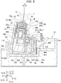
- FIG. 5 is a schematic cross-sectional view taken along line F5-F5 in FIG. 3 .
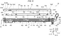
- FIG. 6 is an exploded view of an exposure unit and a moving mechanism in the image forming apparatus of the embodiment.
- the exposure device 43 includes a light source 50, a lens 51, and a holder 52.
- the light source 50 is long in the Y direction. As illustrated in FIG. 5 , the light source 50 includes a plurality of light emitting elements 50a and a circuit board 50b. For example, the plurality of light emitting elements 50a is a solid light emitting element array. For example, the plurality of light emitting elements 50a are arranged in the longitudinal direction of the light source 50. The longitudinal direction of the light source 50 is the Y direction in the image forming apparatus 100.
- the plurality of light emitting elements 50a may be an LED array, an organic EL array, or the like.
- the number of the plurality of light emitting elements 50a is equal to or greater than the number of pixels in a main scanning direction in image formation.
- Each of the plurality of light emitting elements 50a emits light L1 according to a drive current supplied by the circuit board 50b.
- the circuit board 50b turns on and off the plurality of light emitting elements 50a by controlling the drive currents for the plurality of light emitting elements 50a according to a control signal transmitted from the control unit 6.
- Each lens 51 focuses light L1 diverged from each of the plurality of light emitting elements 50a, and forms light L2 that is converged in a spot shape at a focal position on an optical axis L.
- a type of the lens 51 is not particularly limited as long as light L1 from the plurality of light emitting elements 50a can be focused independently.
- a SELFOCK (registered trademark) lens array or the like may be used as the lens 51.
- Optical axes L of lights L1 and L2 from the plurality of light emitting elements 50a are parallel to each other and are inclined by ⁇ with respect to a vertical line in the ZX plane.
- An inclination direction of the optical axis L is the clockwise direction in FIG. 5 .
- the focal position where each light L2 is focused is on the surface of the photoreceptor drum 7 mounted in the image forming apparatus 100.
- An angle of incidence of the optical axis L of light L2 with respect to the photoreceptor drum 7 is not particularly limited.
- the holder 52 is a resin member that holds the light source 50 and the lens 51.
- the holder 52 has an opening through which the lens 51 is inserted and a recess in which the light source 50 is disposed.
- the lens 51 is glued at the opening. If the light source 50 is fixed in the recess, light emitting portions of the plurality of light emitting elements 50a are at front focal points of the lenses 51.
- the moving mechanism 47 includes a casing 40, a stage 60, urging members 44F and 44R, a slider 41, guide members 41A, 41B, and 41C, and an operation unit 46.
- the casing 40 accommodates the stage 60 and the slider 41 inside.
- the casing 40 is mounted in the recess 11a of the base portion 11.
- the casing 40 is placed on a bottom surface 11b of the recess 11a, and is sandwiched between a right side surface 11c and a left side surface 11d protruding from the bottom surface 11b in the Z1 direction.
- the casing 40 is fitted and fixed to a fitting portion formed on the bottom surface 11b, a claw-shaped portion formed on the right side surface 11c, and a fitting portion formed on the left side surface 11d.
- the casing 40 has a bottom surface portion 40a, a first side wall 40b, an upper cover portion 40c, and a second side wall 40d.
- the bottom surface portion 40a, the first side wall 40b, the upper cover portion 40c, and the second side wall 40d are longer in the Y direction than any of the exposure device 43, the stage 60, and the slider 41.
- the bottom surface portion 40a supports the slider 41 to be slidable in the Y direction.
- the bottom surface portion 40a is placed on the bottom surface 11b in the recess 11a.
- a shape of an upper surface of the bottom surface portion 40a is not particularly limited as long as the slider 41 is slidably movable in the Y direction.
- the upper surface of the bottom surface portion 40a may have a flat surface parallel to the XY plane.
- the upper surface of the bottom surface portion 40a may have protrusions or ridges located on a plane parallel to the XY plane.
- the upper surface of the bottom surface portion 40a in the present embodiment has an inclined surface whose normal line direction is the second direction M, at least in the portion where the urging members 44F and 44R are disposed.
- the first side wall 40b extends in the Z1 direction from the end of the bottom surface portion 40a in the X1 direction along the right side surface 11c of the recess 11a.
- the slider 41 is disposed in close proximity to the bottom surface portion 40a on the X2 direction side of the first side wall 40b.
- the upper cover portion 40c is an L-shaped plate-shaped portion on the ZX plane.
- the upper cover portion 40c is formed in a range that covers the upper surface of the slider 41 from above.
- An inclined surface 40e parallel to the second direction M and Y direction is formed at the end portion of the upper cover portion 40c in the X2 direction.
- the second side wall 40d is a flat plate-shaped wall portion parallel to the second direction M and Y direction from the end of the bottom surface portion 40a in the X2 direction.
- the lower end portion of the second side wall 40d is adjacent to and close to the left side surface 11d of the recess 11a.
- a space 40g having a substantially trapezoidal cross section surrounded by the bottom surface portion 40a, the first side wall 40b, and the upper cover portion 40c is long in the Y direction.
- the slider 41 is inserted into the space 40g.
- the upper surface of the bottom surface portion 40a on which the slider 41 is placed slidably supports the slider 41 in the Y direction.
- the lower surface of the upper cover portion 40c guides the upper surface of the slider 41 in the Y direction.
- the side surface of the first side wall 40b on the X2 direction side guides the side surface of the slider 41 on the X1 direction side in the Y direction.
- the space 40g allows the slider 41 to move linearly in the Y direction.
- a distance between an inclined surface 40f on the X1 direction side of the second side wall 40d and the inclined surface 40e of the upper cover portion 40c is slightly wider than a width of the exposure device 43 in the direction orthogonal to the second direction M in the ZX plane. Between the inclined surfaces 40f and 40e, a space 40h is formed in which the exposure device 43 and a part of the stage 60 can move in the second direction M.
- an attachment portion 40i protruding in the Z2 direction further than the bottom surface portion 40a is provided.
- the attachment portion 40i is provided with a boss 40j for attaching the operating portion 46.
- the boss 40j protrudes in the X2 direction from a side portion of the attachment portion 40i.
- the stage 60 includes a holding member 53 and a stay 42.
- the holding member 53 holds the light source 50 and the lens 51 fixed to the holder 52.
- the material of the holding member 53 may be metal or resin.
- the holding member 53 may be made of a composite material of metal and resin. In the examples illustrated in FIGS. 5 and 6 , the holding member 53 has a box shape in which a metal plate such as a mild steel plate or a stainless steel plate is bent.
- the holding member 53 includes the upper plate 53a, a left side plate 53b, a right side plate 53c (see FIG. 5 ), a rear side plate 53fR (see FIG. 6 ), and a front side plate 53fF (see FIG. 6 ).
- the upper plate 53a is a flat plate forming the upper surface of the holding member 53.
- the normal line of the upper plate 53a is parallel to the second direction M.
- the shape of the upper plate 53a when viewed from the second direction M is a rectangular shape long in the Y direction. As illustrated in FIG. 2 , the upper plate 53a is longer than a length of the drum surface of the photoreceptor drum 7.
- an opening 53d is formed in the center of the upper plate 53a in the X direction.
- the upper end of the holder 52 holding the lens 51 is inserted into the opening 53d.
- FIG. 7 is a schematic perspective view illustrating a stage in the image forming apparatus of the embodiment.
- FIG. 8 is a schematic cross-sectional view taken along line F8-F8 in FIG. 7 .
- FIG. 9 is a schematic view of the right side view of the stage in the image forming apparatus.
- the stage 60 includes second positioning portions 53hF and 53hR.
- the second positioning portions 53hF and 53hR are examples of second terminals that are fitted with the first terminals to regulate a relative movement with the photoreceptor in a first direction N.
- the first direction N is the direction from the left side plate 53b toward the right side plate 53c among the directions orthogonal to the second direction M and Y direction.
- the second positioning portion 53hF is provided at an end portion of the upper plate 53a in the Y1 direction.
- the end portion of the upper plate 53a in the Y1 direction means the upper plate 53a in the range between the end of the upper plate 53a and the end of the lens 51 in the Y1 direction.
- the second positioning portion 53hF is provided in a region close to the end of the upper plate 53a in the Y1 direction at the end portion of the upper plate 53a in the Y1 direction.
- the second positioning portion 53hF and the first positioning portion 25eF of the case 25A can be fitted to each other in a concave-convex manner.
- the first positioning portion 25eF is a convex portion and the second positioning portion 53hF is a concave portion.
- the second positioning portion 53hF positions the first positioning portion 25eF in the Y direction.
- the second positioning portion 53hF is fitted with the columnar portion 25ea of the first positioning portion 25eF so that the columnar portion 25ea can be inserted and removed. As illustrated in FIG.
- the second positioning portion 53hF includes a cylindrically tubular portion 53hFa extending in a direction opposite to the second direction M and a curved portion 53hFb that smoothly curves along an arc-shaped curve from the upper end of the tubular portion 53hFa toward the upper plate 53a.
- An inner diameter of the curved portion 53hFb increases in a horn shape from the inner diameter of the tubular portion 53hFa in the second direction M.
- the second positioning portion 53hR is provided at the end portion of the upper plate 53a in the Y2 direction.
- the end portion of the upper plate 53a in the Y2 direction means the upper plate 53a between the end of the upper plate 53a and the end of the lens 51 in the Y2 direction.
- the second positioning portion 53hR is provided in a region close to the end of the upper plate 53a in the Y2 direction at the end portion of the upper plate 53a in the Y2 direction.
- the second positioning portion 53hR and the first positioning portion 25eR of the case 25A can be fitted to each other in a concave-convex manner.
- the first positioning portion 25eR is a convex portion and the second positioning portion 53hR is a concave portion.
- the second positioning portion 53hR positions the first positioning portion 25eR in the X direction.
- the second positioning portion 53hR is a long hole which is long in the Y direction.
- the second positioning portion 53hR has a lateral width that allows the columnar portion 25ea of the first positioning portion 25eR to be inserted and removed in the X direction, and a longitudinal width that is longer than the diameter of the columnar portion 25ea of the first positioning portion 25eR.
- the second positioning portion 53hR includes an elongated cylindrical-shaped tubular portion 53hRa extending in the direction opposite to the second direction M and a curved portion 53hRb that smoothly curves along an arc-shaped curve from the upper end of the tubular portion 53hRa toward the upper plate 53a.
- the lateral width of the curved portion 53hRb increases in a horn shape from the lateral width of the tubular portion 53hRa in the second direction M, similarly to the curved portion 53hFb. The same applies to the cross-sectional shape of the longitudinal width.
- the second positioning portions 53hF and 53hR are separated from the light source 50 and sandwich the light source 50 in between, in the Y direction.
- the second positioning portions 53hF and 53hR position the holding member 53 in the Y direction and in the first direction N intersecting the Y direction with respect to the abutment portions 25fF and 25fR by being fitted with the first positioning portions 25eF and 25eR, respectively.
- the first positioning portions 25eF and 25eR are provided on the photoreceptor unit 25D and can be fitted to the second positioning portions 53hF and 53hR of the stage 60 in a concave-convex manner at the first position to position the stage 60 in a direction intersecting the second direction M.
- the directions intersecting the second direction M are the lateral direction and the longitudinal direction of the upper plate 53a among the directions along the upper plate 53a.
- the stage 60 can be moved from the first position closer to the photoreceptor to the second position farther from the photoreceptor in the second direction than the first position to fit the second terminal into the first terminal.
- an abutment portion 53gF against which the tip of the abutment portion 25fF can abut is provided next to the second positioning portion 53hF in the Y2 direction.
- the shape of the abutment portion 53gF is not particularly limited as long as the abutment portion 53gF can abut on the abutment portion 25fF.
- the abutment portion 53gF is a planar surface of the upper plate 53a sandwiched between two slits 53i that are long in the X direction and separated from each other in the Y direction.
- an abutment portion 53gR to which the tip of the abutment portion 25fR can abut is provided next to the second positioning portion 53hR in the Y1 direction.
- the shape of the abutment portion 53gR is not particularly limited as long as the abutment portion 53gR can abut on the abutment portion 25fR.
- an abutment portion 53gF is a planar surface of the upper plate 53a sandwiched between the two slits 53i, like the abutment portion 53gF.
- the holding member 53, the stage 60 including the holding member 53, and the exposure device 43 held by the stage 60 are respectively positioned at the first position.
- the left side plate 53b is bent from the end of the upper plate 53a in the X2 direction in the direction opposite to the second direction M.
- the right side plate 53c is bent from the end of the upper plate 53a in the X1 direction in the direction opposite to the second direction M.
- An outer shape of the left side plate 53b when viewed from the X1 direction is a rectangular shape long in the Y direction (see FIG. 6 ).
- the outer shape of the right side plate 53c when viewed from the X2 direction is a rectangular shape long in the Y direction similar to the left side plate 53b (see FIG. 9 ).
- the rear side plate 53fR is bent in the Z2 direction from the end of the upper plate 53a in the Y2 direction.
- the length of the rear side plate 53fR in the Z direction is substantially equal to the length of the left side plate 53b in the Z direction.
- the front side plate 53fF is bent in the Z2 direction from the end of the upper plate 53a in the Y1 direction.
- the length of the front plate 53fF in the Z direction is substantially equal to the length of the left plate 53b in the Z direction.
- holes 53A, 53B, 53C, and 53D penetrate through a portion near the lower end (end in the Z2 direction) of the left side plate 53b in the thickness direction.
- the hole centers of the holes 53A, 53B, 53C, and 53D are on the same straight line parallel to the upper plate 53a.
- the holes 53A, 53B, 53C, and 53D penetrate through the right side plate 53c in the thickness direction at the same positions as in the left side plate 53b.
- the overall shape of the holding member 53 is a box shape in which the left side plate 53b, the rear side plate 53fR, the right side plate 53c, and the front side plate 53fF are erected on the outer edge of the upper plate 53a.
- the stay 42 is shorter than the holding member 53 and longer than the distance between the hole 53A and the hole 53D in the Y direction.
- the width of the upper part of the stay 42 in the X direction is a size that can be inserted inside the holding member 53.
- the stay 42 is connected to the holding member 53 with the upper part of the stay 42 inserted inside the holding member 53.
- the stay 42 is made of resin, for example.
- the shape of the stay 42 is a plate shape long in the Y direction as a whole.
- the stay 42 has side plate portions 42b and 42c.
- the side plate portions 42b and 42c are flat plates parallel to the second direction M and the Y direction.
- the side plate portions 42b and 42c are disposed in this order in the X1 direction, and face each other in the respective plate thickness directions.
- the side plate portions 42b and 42c are connected to each other in the facing direction by a plurality of ribs.
- protrusions 42A, 42B, 42C, and 42D that are fitted from the inside into the holes 53A, 53B, 53C, and 53D in the left side plate 53b, respectively, protrude to the side opposite to the side plate portion 42c (see FIG. 7 ).
- the protrusions 42A, 42B, 42C, and 42D that are fitted from the inside into the holes 53A, 53B, 53C, and 53D in the right side plate 53c, respectively, protrude to the side opposite to the side plate portion 42b (see FIG. 7 ).
- the shapes of the protrusions 42A, 42B, 42C, and 42D provided on the side plate portion 42c are the same as those of the protrusions 42A, 42B, 42C, and 42D provided on the side plate portion 42b, except for the protruding direction.
- the protrusions 42A, 42B, 42C, and 42D are formed on the side plate portions 42b and 42c which are divided into pieced portion by slits formed in the vicinity thereof.
- the protrusions 42A, 42B, 42C, and 42D can be inserted inside the holding member 53 by elastic deformation of respective pieced portions. After insertion, the protrusions 42A, 42B, 42C, and 42D are respectively urged toward the holes 53A, 53B, 53C, and 53D by the elastic restoring force of the respective pieced portions, and are respectively fitted to the holes 53A, 53B, 53C, and 53D from the inside of the holding member 53.
- the holding member 53 and the stay 42 are coupled each other by fitting the holes 53A, 53B, 53C, and 53D with the protrusions 42A, 42B, 42C, and 42D, respectively.
- the protrusions 42A, 42B, 42C, and 42D do not protrude to the outside of the left side plate 53b and the right side plate 53c, or even if the protrusions 42A, 42B, 42C, and 42D protrude, the protrusion is very slight.
- protrusions 42A, 42B, 42C, and 42D will be described below with an example in which the protrusions 42A, 42B, 42C, and 42D do not protrude to the outside of the left side plate 53b and the right side plate 53c.
- the width of the stage 60 (hereinafter referred to as the lateral width) in the first direction N is narrower than the interval between the inclined surfaces 40e and 40f.
- the stage 60 is movable in the second direction M and the first direction N between the inclined surfaces 40e and 40f in the casing 40.
- a step portion 42i long in the Y direction protrudes between the protrusions 42A and 42B adjacent to each other in the Y direction.
- the step portions 42i long in the Y direction respectively protrude between the protrusions 42B and 42C and between the protrusions 42C and 42D, which are adjacent to each other in the Y direction.
- the range of the lateral width of each step portion 42i is from the lower end of the right side plate 53c coupled to the stay 42 to the lower end of the side plate portion 42c.
- the protruding heights of the step portions 42i are equal to each other. As illustrated in FIG. 5 , the surface of each step portion 42i in the protruding direction is substantially flush with the surface of the right side plate 53c on the X1 direction side.
- a side surface portion 42h formed in the protruding direction in each step portion 42i is provided with a first protrusion 42j in an intermediate portion in the longitudinal direction and the lateral direction.
- the side surface portion 42h is an example of a base portion provided on the stage 60.
- each first protrusion 42j protrudes from the side surface portion 42h in a direction intersecting the second direction M.
- each first protrusions 42j protrudes in the X1 direction.
- Each first protrusion 42j is inclined counterclockwise in FIG. 5 by an angle ⁇ with respect to the normal line of the side surface portion 42h in the ZX plane.
- the shape of the first protrusion 42j is not particularly limited as long as the upper surface can be slidably locked to the slider 41.
- the first protrusion 42j may be a column, an elliptical column, a rod whose end face in the Z1 direction is rounded into a cylindrical surface shape, a polygonal pillar, or the like.
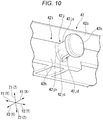
- FIG. 10 is a schematic perspective view illustrating the first protrusion in the moving mechanism of the embodiment.
- the first protrusion 42j in the present embodiment has a first curved surface 42ja, side surfaces 42jb, a second curved surface 42jc, and a slit 42jd.
- the first curved surface 42ja is the upper surface of the first protrusion 42j, and has a cylindrical surface shape in which an upwardly convex semicircle is extended in the X1 direction.
- Each of the side surfaces 42jb extend in the Z1 direction from both lower ends of the first curved surface 42ja.
- Each side surface 42jb is a flat surface parallel to the ZX plane.
- the second curved surface 42jc is the lower surface of the first protrusion 42j, and has a cylindrical surface shape in which a downwardly convex semicircle is extended in the X1 direction.
- the slit 42jd is formed in the Z1 direction from the central portion of the second curved surface 42jc, and is a groove portion long in the X1 direction.
- the slit 42jd is provided to reduce an average wall thickness of the first protrusion 42j.
- a second protrusion 42k protruding from the first protrusion 42j in the direction along the side surface portion 42h is provided.
- the second protrusion 42k may protrude from at least one surface of the first protrusion 42j in the Z1 direction and the Z2 direction.
- the second protrusion 42k in the example illustrated in FIG. 10 has a flange shape that protrudes from the entire peripheral surface of the first protrusion 42j.
- the second protrusion 42k has a plate shape having a substantially circular outer shape when viewed from the X2 direction. As illustrated in FIG. 5 , a surface 42ka of the second protrusion 42k facing the step portion 42i side is a flat surface parallel to the side surface portion 42h.
- the urging members 44F and 44R are provided between the bottom surface portion 40a of the casing 40 and the holding member 53.
- the urging members 44F and 44R urge the holding member 53 in the second direction M.
- the urging members 44F and 44R are not particularly limited as long as the holding member 53 can be urged in the second direction M.
- elastic springs, elastic bodies, and the like may be used for the urging members 44F and 44R.
- the urging members 44F and 44R are compression coil springs.
- the urging member 44F urges the end portion of the holding member 53 in the Y1 direction from the back surface of the upper plate 53a.
- the urging member 44F may urge the holding member 53 at a position overlapping the abutment portion 53gF in the second direction M.
- the urging member 44R urges the end portion of the holding member 53 in the Y2 direction from the back surface of the upper plate 53a.
- the urging member 44R may urge the holding member 53 at a position overlapping the abutment portion 53gR in the second direction M.
- the slider 41 will be described.
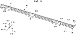
- FIG. 11 is a schematic perspective view illustrating the entire slider in the moving mechanism of the embodiment.
- the slider 41 has a thin plate shape in the X direction as a whole and is long in the Y direction.
- the cross section of the slider 41 parallel to the ZX plane is a substantially trapezoidal shape accommodated in the space 40g of the casing 40.
- the slider 41 is disposed next to the stay 42 in the X1 direction inside the space 40g.
- the slider 41 has a bottom surface 41a, a side plate 41b, an upper surface portion 41c, and a side surface 41d on the outer peripheral portion.
- the bottom surface 41a is a flat surface slidable in the Y direction.
- the bottom surface portion 40a is formed at a plurality of locations in the Y direction.
- the side plate 41b extends in the Z1 direction along the first side wall 40b of the casing 40. Ridges 41e long in the Y direction are provided at the upper end and the lower end of the side plate 41b, respectively. Each ridge 41e can abut on the inner surface of the first side wall 40b. Each ridge 41e reduces sliding resistance of the slider 41 in the Y direction when the ridge 41e abuts on the first side wall 40b.
- the upper surface portion 41c has a surface shape that can slide with the lower surface of the upper cover portion 40c of the casing 40 in the Y direction.
- the side surface 41d forms an end face of the slider 41 in the X2 direction.
- the side surface 41d is an inclined surface inclined by an angle ⁇ clockwise with respect to the YZ plane when viewed from the Y2 direction.
- the side surface 41d is formed at a position where the side surface 41d does not protrude in the X2 direction further than the same plane as the inclined surface 40e of the casing 40 in a movable range of the slider 41 in the X direction in the space 40g.
- the side surface 41d faces the side surface portion 42h and the right side plate 53c of the stage 60 with a gap in the X1 direction.
- a boss 41f that protrudes in the X2 direction further than the side surface 41d is provided at the end portion of the slider 41 in the Y1 direction.
- the operation unit 46 is attached to the boss 41f.
- the slider 41 can move in the Y direction in the casing 40.
- the Y1 direction or the Y2 direction is an example of a third direction that intersects the second direction M and the X1 direction which is an example of the first direction.
- the slider 41 includes the guide members 41A, 41B, and 41C on a part of the side surface 41d.
- the guide members 41A, 41B, and 41C convert the movement of the slider 41 in the Y direction into the movement in the Z1 direction and transmit the movement to the first protrusions 42j.
- the guide members 41A, 41B, and 41C are formed on the slider 41 at the same disposition intervals as those of the three first protrusions 42j on the stay 42.
- the guide member 41A Since the configurations of the guide members 41A, 41B, and 41C are the same as each other, the guide member 41A will be described below as an example.
- FIG. 12 is a schematic perspective view illustrating a main part of the slider in the moving mechanism of the embodiment.
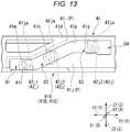
- FIG. 13 is a schematic view of the left side view of the guide member in the moving mechanism.
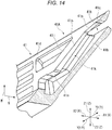
- FIG. 14 is a schematic perspective view illustrating the guide member in the moving mechanism.
- the guide member 41A is disposed to face the side plate 41b in the X direction, and is configured with a plate P whose surface in the X2 direction forms the side surface 41d.
- a through-hole G penetrating in the X1 direction is formed in the plate P.
- the first protrusion 42j between the protrusions 42A and 42B is inserted into the through-hole G (see FIG. 5 ).
- the plate P includes a first guide plate 41i on the Z1 direction side of the through-hole G and a second guide plate 41j on the Z2 direction side of the through-hole G.
- the edge of the first guide plate 41i in the Z2 direction forms the inner surface of the through-hole G in the Z1 direction.
- the edge of the second guide plate 41j in the Z1 direction forms the inner surface of the through-hole G in the Z2 direction.
- the through-hole G includes a first guide G1, a second guide G2, a third guide G3, and an insertion hole portion G4 when viewed from the X1 direction.
- the first guide G1 is a hole portion of the guide member 41A from the end in the Y2 direction toward the Y1 direction.
- the inner surface in the first guide G1 in the Z1 direction is a locking portion 41m that locks the first protrusion 42j in the Z1 direction.
- the stage 60 is in the second position if the first protrusion 42j is locked to the locking portion 41m.
- the locking portion 41m also moves the stage 60 to the lowermost side in a movement range of the stage 60 in the second direction M.
- the locking portion 41m is an example of a second position regulation portion that abuts on the first protrusion 42j if the stage 60 is in the second position.
- the locking portion 41m is a flat surface parallel to the XY plane.
- the inner surface of the first guide G1 in the Z2 direction is a lower surface 41r parallel to the locking portion 41m.
- the second guide G2 is a hole portion that inclines toward the Z1 direction from the end of the first guide G1 in the Y1 direction in accompaniment to advancing in the Y1 direction.
- the inner surface of the second guide G2 in the Z1 direction is guide portions 41n and 41p that raise the position of the first protrusion 42j.
- the guide portion 41n is connected to the end of the locking portion 41m in the Y1 direction.
- the guide portion 41p is connected to the end of the guide portion 41n in the Y1 direction.
- the inclination of the guide portion 41p is smaller than the inclination of the guide portion 41n.
- the guide portion 41p changes an ascending amount of the stage 60 when approaching the first position more gently than the guide portion 41n. If the stage 60 may be made to ascend at a constant rate from the second position to the first position, the guide portion 41p may be omitted.
- the third guide G3 is a hole portion of the second guide G2 from the end in the Y1 direction toward the Y1 direction.
- the inner surface of the third guide G3 in the Z1 direction is a stopper surface 41q that regulates an ascending position of the first protrusion 42j.
- the stopper surface 41q is parallel to the XY plane.
- the stopper surface 41q is an example of a first position regulation portion that regulates the position of the first protrusion 42j in the second direction M if the stage 60 is in the first position.
- the first position regulation portion and the second position regulation portion are separated from each other in the Y direction, which is the third direction from each other.
- the insertion hole portion G4 is a hole portion from the end of the third guide G3 in the Y1 direction toward the end of the through-hole G in the Y1 direction.
- the opening width of each of the first guide G1, the second guide G2, and the third guide G3 in the Z direction is wider than the width of the first protrusion 42j in the Z direction and narrower than the width of the second protrusion 42k in the Z direction.
- the insertion hole portion G4 has an opening larger than the outer shape of the second protrusion 42k.
- the insertion hole portion G4 is used for inserting the second protrusion 42k into the through-hole G during manufacturing.
- the length of the through-hole G in the Y direction is longer than a moving stroke of the slider 41 in the Y direction.
- the first protrusion 42j faces the locking portion 41m in the Z direction, as illustrated by a first protrusion 42j1.
- a gap is formed between the first protrusion 42j locked with the locking portion 41m and the lower surface 41r.
- the first protrusion 42j faces the stopper surface 41q in the Z direction, as illustrated by a first protrusion 42j3.
- the first protrusion 42j faces the guide portion 41n in the Z direction, as illustrated by a first protrusion 42j2.
- the bottom surface 41a is provided on the Z2 direction side of the guide member 41A within a range similar to the length of the guide member 41A in the Y direction.
- a substantially rectangular lower opening 41g is formed when viewed from the Z1 direction.
- the upper surface portion 41c is formed with an upper opening 41h that penetrates in a range that overlaps a part of the third guide G3 and the insertion hole portion G4 when viewed from the X1 direction.
- the second protrusion 42k can enter the upper opening 41h (see FIG. 5 ).
- the thickness of the plate P decreases uniformly in accompaniment to advancing in the second direction M, at least above the lower surface 41r in the range where the through-hole G is formed.
- the plate thickness of the plate P is the thickest at a height or less of the lower surface 41r and the minimum at the upper end of the plate P.
- the plate thickness of the guide portions 41n and 41p in the X1 direction uniformly decreases from the plate thickness of the locking portion 41m in accompaniment to advancing in the second direction M.
- the plate thickness increases uniformly in accompaniment to advancing in the second direction M.
- the thickness of the stopper surface 41q in the first direction N is thinner than the thickness of the locking portion 41m.
- the slider 41 is made of resin.
- a decrease rate of the plate thickness of the plate P is larger than the reduction rate based on an average draft of the slider 41.
- the operation unit 46 advances and retreats the slider 41 in the Y direction with respect to the casing 40.
- the operation unit 46 is a lever that rotates along the YZ plane.
- the operation unit 46 includes an elongated lever body 46b and a link 46d that connects the lever body 46b to the slider 41.
- a first end portion of the lever body 46b in the length direction is rotatably connected to the tip of the boss 40j of the casing 40 via a rotating joint 46c.
- the rotating joint 46c rotatably supports the lever body 46b around the central axis of the boss 40j.
- the central axis of the boss 40j is parallel to the X direction.
- a grip portion 46a that can be gripped by a user is provided at a second end portion opposite to the first end portion in the length direction of the lever body 46b.
- a rotating joint 46f that connects to the link 46d is provided between the first end portion and the second end portion in the length direction of the lever body 46b.
- the first end portion of the link 46d in the length direction is rotatably connected to the lever body 46b via the rotating joint 46f.
- the second end portion opposite to the first end portion in the length direction of the link 46d is rotatably connected to the tip of the boss 41f of the slider 41 via a rotating joint 46e.
- the link 46d can rotate relative to the lever body 46b around the rotating joint 46f, with respect to the lever body 46b that rotates around the rotating joint 46c.
- the operation of the moving mechanism 47 in the image forming apparatus 100 will be described focusing on actions of the guide members 41A, 41B, and 41C.
- the stage 60 can be made to ascend and descend by the moving mechanism 47 with respect to the casing 40 in the second direction M.
- the holding member 53 of the stage 60 abuts on the abutment portions 25fF and 25fR at the abutment portions 53gF and 53gR.
- the stage 60 is in the first position. At the first position, a posterior focal point of the lens 51 is on the surface of the photoreceptor drum 7.
- the holding member 53 presses the abutment portions 25fF and 25fR in the second direction M by the urging force from the urging members 44F and 44R.
- FIG. 15 is a schematic view of the left side view illustrating the exposure unit and the moving mechanism if descending in the image forming apparatus of the embodiment.
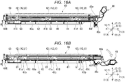
- FIG. 16 is a schematic diagram illustrating the operation of the moving mechanism in the image forming apparatus.
- FIG. 16 is a schematic view illustrating a force acting on a stay in the image forming apparatus.
- (a) illustrates a case of the first position
- (b) illustrates a case of the second position.
- each of the first protrusions 42j is located inside the third guide G3 like the first protrusion 42j3 illustrated in FIG. 13 .
- the stay 42 is moved in the Y1 direction by the operation unit 46 that is rotated clockwise and oriented horizontally. Since the guide members 41A, 41B, and 41C also move in the Y1 direction together with the stay 42, each of the first protrusions 42j abuts on the guide portion 41n and is pressed by the guide portion 41n in the direction opposite to the second direction M.
- Each first protrusion 42j moves to the first guide G1 lower than the third guide G3 while being guided by the guide portion 41n.
- each first protrusion 42j abuts on the locking portion 41m and is pressed by the locking portion 41m in the direction opposite to the second direction M.
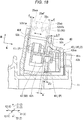
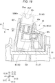
- FIGS. 17 , 18 and 19 are schematic views illustrating an ascending and descending operation of the stage of the moving mechanism of the embodiment.
- FIG. 17 illustrates a cross section when the stage 60 is in the second position.
- the first protrusion 42j is disposed at the same position as the first protrusion 42j1 in FIG. 13 .
- the upper end of the first protrusion 42j is locked to the locking portion 41m.
- Each of the gap between the left side plate 53b of the holding member 53 and the inclined surface 40f and the gap between the right side plate 53c and the inclined surface 40e is d.
- the distance between the side surface portion 42h and the inclined surface 40e is w.
- the distance between the lowermost end of the surface 42ka and the second guide plate 41j in the first direction N is a distance ⁇ 1.
- the interval between an intersection of the first curved surface 42ja and the surface 42ka and the first guide plate 41i in the first direction N is a distance ⁇ 1. Since the plate thickness of the plate P becomes thinner in accompaniment to advancing in the second direction M, ⁇ 1 is larger than ⁇ 1.
- the movement range of the stage 60 in the first direction N becomes smaller than d.
- FIG. 18 illustrates a cross section of the stage 60 in the process of moving from the second position to the first position.
- the first protrusion 42j is in the same position as the first protrusion 42j2 in FIG. 13 .
- the upper end of the first protrusion 42j is being abutted on the guide portion 41n and is ascending along the inclination of the guide portion 41n.
- the distance between the lowermost end of the second protrusion 42k and the second guide plate 41j is a distance ⁇ 2.
- the interval between the intersection of the first curved surface 42ja and the surface 42ka and the first guide plate 41i in the first direction N is a distance ⁇ 2.
- ⁇ 2 is larger than ⁇ 1 and ⁇ 2 is larger than ⁇ 1.
- the movement range of the stage 60 in the first direction N becomes smaller than d. Since ⁇ 2 is larger than ⁇ 1, the movement range of the stage 60 in the first direction N is larger than that of the stage 60 in the second position.
- an abutment length between the first protrusion 42j and the first guide plate 41i is smaller than the abutment length at the second position. Since the abutment length between the first protrusion 42j and the first guide plate 41i gradually decreases as the stage 60 ascends, the frictional force generated between the first protrusion 42j and the first guide plate 41i gradually decreases.
- the upper plate 53a approaches the first positioning portion 25eF.
- the first positioning portion 25eF and the central axis of the tubular portion 53hF of the second positioning portion 53hF are misaligned due to variations in parts, assembly errors during manufacturing, and the like, the first positioning portion 25eF cannot be fitted to the tubular portion 53hFa, or a large force is required when fitting the first positioning portion 25eF to the tubular portion 53hFa. If the force required when fitting exceeds the urging force of the urging members 44F and 44R, the stage 60 may not be able to ascend before moving to the first position.
- the curved portion 53hFb whose diameter is widened upward is provided at the upper end of the tubular portion 53hFa and the tapered portion 25eb is formed at the lower end of the first positioning portion 25eF, the deviation between the axis of the first positioning portion 25eF and the central axis of the tubular portion 53hFa can be absorbed to some extent.
- the deviation between the axis of the first positioning portion 25eF and the central axis of the tubular portion 53hFa is easily absorbed even at the point that the movement range of the stage 60 in the first direction N is widened.
- FIG. 19 illustrates a cross section when the stage 60 is in the first position.
- the first protrusion 42j is in the same position as the first protrusion 42j3 in FIG. 13 .
- the columnar portion 25ea of the first positioning portion 25eF is fitted with the tubular portion 53hFa, and the stage 60 is positioned in the first direction N and Y direction. Since the upper plate 53a abuts on the abutment portion 25fF, the stage 60 is positioned at the first position in the second direction M.
- the first protrusion 42j is moved inside the third guide G3 and is separated from the second guide plate 41j. Since the external force from the second guide plate 41j does not act on the stay 42 through the first protrusion 42j, the stage 60 is pressed against the abutment portion 25fF by the urging force of the urging member 44F.
- the relative operation of the first positioning portion 25eR and the second positioning portion 53hR is the same as the relative operation of the first positioning portion 25eR and the second positioning portion 53hR, except that the second positioning portion 53hR does not position in the Y direction of the first positioning portion 25eR.
- each exposure unit 26 is mounted in the printer unit 3 so that the holding member 53 is in the first position. At the first position, the focal position of the lens 51 is aligned with the surface of the photoreceptor drum 7.
- Image formation is started by the operation of the control panel 1 or an external signal.
- Image information is transmitted to the printer unit 3 by reading an object to be copied by the scanner unit 2, or is transmitted to the printer unit 3 from the outside.
- the printer unit 3 supplies the sheet S in the sheet supply unit 4 or the sheet S in the manual feed unit 10 to the registration roller 24 based on a control signal generated by the control unit 6 based on the operation of the control panel 1 or the external signal.
- control unit 6 controls, for example, to start feeding the sheet S and forming an image.
- Each exposure unit 26 exposes each of the photoreceptor drums 7 of the image forming unit 25Y, 25M, 25C, and 25K based on image information corresponding to a color transmitted from the control unit 6 to form an electrostatic latent image corresponding to each image information.
- Each electrostatic latent image is developed by the developing device 8. Therefore, a toner image corresponding to the electrostatic latent image is formed on the surface of each photoreceptor drum 7.
- Each toner image is primarily-transferred to the intermediate transfer belt 27 by each transfer roller. As the intermediate transfer belt 27 moves, the toner images are sequentially superposed without causing color shift and delivered to the transfer unit 28.
- the sheet S is fed from the registration roller 24 to the transfer unit 28.
- the toner image that reaches the transfer unit 28 is secondarily-transferred to the sheet S.
- the secondarily-transferred toner image is fixed to the sheet S by the fixing device 29. With such configuration, an image is formed on the sheet S.
- the photoreceptor unit 25D may need to be pulled out from the apparatus for maintenance.
- the user tilts the operation unit 46 of the moving mechanism 47 toward the Y1 direction to move the stage 60 to the second position.
- the stage 60 is separated downward from the abutment portions 25fF and 25fR.
- the exposure device 43 fixed to the stage 60 also descends together with the stage 60. Since a gap is formed above the upper plate 53a and above the lens 51 according to a descending amount of the stage 60, the photoreceptor unit 25D is pulled out in the Y1 direction without interfering with the exposure unit 26.
- the photoreceptor unit 25D After maintenance of the photoreceptor unit 25D is completed, the photoreceptor unit 25D is returned to the printer unit 3, and then the operation unit 46 is erected to move the stage 60 to the first position.
- the stage 60 is similarly moved to the second position even when cleaning the lens 51.
- a cleaner erects the operation unit 46 and moves the stage 60 to the first position.
- the holding member 53 can be switched between the second position and the first position by operating the operation unit 46. Since the operation of the operation unit 46 is only to switch the rotation position around the rotating joint 46c, the operation unit 46 can be easily operated.
- the moving mechanism 47 According to the moving mechanism 47, the thickness of each of the first guide plate 41i and the second guide plate 41j of the slider 41 becomes thinner in accompaniment to advancing in the second direction M. At the second position, the position blurring of the stage 60 in the first direction N is reduced. The moving mechanism 47 can stably hold the stage 60 in the second position.
- the movable range of the stage 60 in the first direction N increases in the vicinity of the first position, for example, even if the axes of the first positioning portions 25eF and 25eR and the central axes of the second positioning portions 53hF and 53hR are misaligned due to variations in parts and assembly errors during manufacturing, the first positioning portions 25eF and 25eR can be smoothly fitted to the second positioning portions 53hF and 53hR.
- the moving mechanism 47 can move the stage 60 to the first position accurately and smoothly.
- the moving mechanism 47 and the image forming apparatus 100 that facilitate the positioning of the stage 60 and the operation of the stage 60.
- FIG. 20 is a schematic cross-sectional view illustrating a moving mechanism of a first modification example of the embodiment.
- a moving mechanism 47A of the first modification example illustrated in FIG. 20 includes a slider 141 instead of the slider 41 of the moving mechanism 47 of the embodiment.
- the moving mechanism 47A can be used in the image forming apparatus 100 instead of the moving mechanism 47.
- the slider 141 includes a first guide plate 41iA instead of the first guide plate 41i of the slider 41.
- the first guide plate 41iA includes a plate PA instead of the plate P of the slider 41.
- the plate PA is different from the plate P in that the surface in the first direction N has a side surface Pa parallel to the side surface 41d and an inclined surface Pb that approaches the side surface 41d in accompaniment to advancing from the upper end of the side surface Pa to the second direction M.
- the side surface Pa is formed at a height from the end of the plate PA in the Z2 direction to the locking portion 41m.
- the inclined surface Pb is formed on the first guide plate 41i and the second guide plate 41j on the second direction M side of the locking portion 41m.
- the distance between the side surface Pa and the surface 42ka of the second protrusion 42k is ⁇ 1. While the second protrusion 42k faces the side surface Pa, the movement range of the stage 60 in the first direction N is limited to the ranges of w and ⁇ 1.
- the distance between the inclined surface Pb and the surface 42ka of the second protrusion 42k is determined according to an inclination amount of the inclined surface Pb, and gradually decreases from ⁇ 1 in accompaniment to advancing in the second direction M.
- FIG. 21 is a schematic cross-sectional view illustrating a moving mechanism of a second modification example of the embodiment.
- a moving mechanism 47B of the second modification example illustrated in FIG. 21 includes a stay 242 instead of the stay 42 of the moving mechanism 47 of the embodiment.
- the moving mechanism 47B can be used in the image forming apparatus 100 instead of the moving mechanism 47.
- the stay 242 includes a second protrusion 42kB instead of the second protrusion 42k of the slider 41.
- the second protrusion 42kB has a flange shape in which the lower end portion does not protrude further than a second curved surface 42jp.
- the surface 42ka of the second protrusion 42kB faces the surface of the first guide plate 41i on the first direction N side, but does not face the second guide plate 41j.
- the interval between the intersection of the first curved surface 42ja and the surface 42ka and the first guide plate 41i is set to ⁇ 1. Since the second protrusion 42kB does not protrude below the second curved surface 42jc, even if the interval between the upper end and the first guide plate 41i is narrowed as in ⁇ 1, the lower end of the second protrusion 42kB does not interfere with the second guide plate 41j.
- the modification example is an example if the second guide plate 41j is not used to regulate the movement range of the stage 60 in the first direction N.
- the first guide plate 41i and the second protrusion 42kB can exert the effect similar to that of the embodiment.
- the second guide plate 41j configuring a part of the through-hole G can be deleted if strength is not needed.
- the first positioning portion and the second positioning portion are respectively described as the columnar pin and the hole.
- the first positioning portion and the second positioning portion are not limited thereto as long as the first positioning portion and the second positioning portion can be fitted to each other in a concave-convex manner.
- the second positioning portion may be a columnar pin
- the first positioning portion may be a hole.
- a concave portion used for the concave-convex fitting may be a concave portion other than the hole.
- the concave portion may be a bottomed hole.
- pins and protrusions having various cross-sectional shapes other than the column may be used.
- the operation unit in the moving mechanism is described as a lever that rotates in the YZ plane.
- the operation unit is not limited to the lever that rotates in the YZ plane as long as the operation to move the guide member in the Y direction is possible.
- the stage of the moving mechanism holds the exposure device and is used for ascending and descending of the exposure device in the image forming apparatus 100 is described.
- a component other than the exposure device may be mounted on the stage .
- the moving mechanism may be used in equipment other than the image forming apparatus.
- a stage which has the first and second protrusions and a guide member which reduces the pressure in accompaniment to advancing in the second direction
- a moving mechanism and an image forming apparatus that facilitates positioning of the stage and operation of the stage are provided.
Landscapes
- Physics & Mathematics (AREA)
- General Physics & Mathematics (AREA)
- Electrophotography Configuration And Component (AREA)
- Printers Or Recording Devices Using Electromagnetic And Radiation Means (AREA)
- Exposure Or Original Feeding In Electrophotography (AREA)
Abstract
Description
- This application is based upon and claims the benefit of priority from Japanese Patent Application No.
2020-039088, filed on March 6, 2020 - Embodiments described herein relate generally to a moving mechanism and an image forming apparatus.
- As an exposure light source of the image forming apparatus, for example, a line-type light source such as an LED array may be used. The line-type light source is held in an exposure device. Light emitted from the line-type light source is focused on a line by a lens included in the exposure device. The exposure device is supported by a moving mechanism which advances toward and retreats from a photoreceptor unit including a photoreceptor.
- The moving mechanism moves the exposure device between an abutment position where the exposure device abuts on the photoreceptor unit and a separation position where the exposure device is separated from the photoreceptor unit. At the abutment position, the exposure device is positioned with respect to the photoreceptor so that the emitted light is focused at an exposure position on a surface of a photoreceptor drum.
- For example, if a movement path in the moving mechanism varies due to a component error, an assembly error, or the like, positioning at the abutment position may be hindered.
- One of the objects of the present invention is to improve prior art techniques and overcome at least some of the prior art problems as for instance above illustrated.
- According to a first aspect of the invention, it is provided an image forming apparatus, comprising: a photoreceptor component comprising a photoreceptor configured to carry an electrostatic latent image; a first terminal configured to be supported by the photoreceptor component; a stage comprising a second terminal that fits with the first terminal and configured to regulate a relative movement in a first direction with the photoreceptor and to move from a first position closer to the photoreceptor to a second position farther from the photoreceptor in a second direction opposite to the first position so that the second terminal fits with the first terminal; a first protrusion that protrudes from a base portion provided on the stage in a direction intersecting the second direction; a second protrusion that protrudes in a direction intersecting the first direction from the first protrusion at a position separated from the base portion in the first direction; a slider configured to move in a third direction that intersects the second direction and the first direction, in which a thickness of a first position regulation portion in the first direction that regulates a position of the first protrusion in the second direction when the stage is in the first position is thinner than a thickness of a second position regulation portion in the first direction that abuts on the first protrusion when the stage is in the second position, include the first position regulation portion and the second position regulation portion at positions separated from each other in the third direction, and slide with the first protrusion between the base portion and the second protrusion and include a guide portion which is long in the third direction between the second position regulation portion and the first position regulation portion; and an exposure device configured to be supported by the stage and to emit light to draw an electrostatic latent image on the photoreceptor.
- Optionally, in the image forming apparatus according to the first aspect of the invention, the thickness of the second position regulation portion in the first direction is a size that fits in a gap between the base portion and the second protrusion.
- Optionally, in the image forming apparatus according to the second aspect of the invention, the guide portion is inclined in a direction that diagonally intersects the second direction when viewed from the first direction.
- Optionally, in the image forming apparatus according to the second aspect of the invention, the first terminal comprises a shaft member long in the second direction, and the second terminal comprises a tubular portion configured to fit to the first terminal at least in the first direction and a curved portion whose diameter gradually increases from an end of the tubular portion in the second direction toward the second direction.
- Optionally, in the image forming apparatus according to the second aspect of the invention, the photoreceptor is a photoreceptor drum.
- Optionally, in the image forming apparatus according to the second aspect of the invention, the second terminal fits with the first terminal in a concave-convex manner.
- Optionally, in the image forming apparatus according to the second aspect of the invention, the third direction intersects the second direction and the first direction in a perpendicular manner.
- Optionally, in the image forming apparatus according to the second aspect of the invention, the first protrusion comprises a columnar portion and a tapered portion.
- Optionally, in the image forming apparatus according to the second aspect of the invention, the second protrusion comprises a columnar portion and a tapered portion.
- Optionally, in the image forming apparatus according to the second aspect of the invention, the slider has a cross section having a substantially trapezoidal shape.
- According to a second aspect of the invention, it is provided a moving mechanism for an image forming apparatus which includes a photoreceptor configured to carry an electrostatic latent image, a first terminal, and an exposure device that emits light to draw an electrostatic latent image on the photoreceptor, the moving mechanism comprising: a stage comprising a second terminal that fits with the first terminal and configured to regulate a relative movement in a first direction with the photoreceptor, to move from a first position closer to the photoreceptor to a second position farther from the photoreceptor in a second direction opposite the first position so that the second terminal fits with the first terminal, and to support the exposure device; a first protrusion that protrudes from a base portion provided on the stage in a direction intersecting the second direction; a second protrusion that protrudes in a direction intersecting the first direction from the first protrusion at a position separated from the base portion in the first direction; and a slider configured to move in a third direction that intersects the second direction and the first direction, in which a thickness of a first position regulation portion that regulates a position of the first protrusion in the second direction when the stage is in the first position is thinner than a thickness of a second position regulation portion that abuts on the first protrusion in the first direction when the stage is in the second position, include the first position regulation portion and the second position regulation portion at positions separated from each other in the third direction, and slide with the first protrusion between the base portion and the second protrusion and include a guide portion which is long in the third direction between the second position regulation portion and the first position regulation portion.
- Optionally, in the moving mechanism according to the second aspect of the invention, the thickness of the second position regulation portion in the first direction is a size that fits in a gap between the base portion and the second protrusion.
- Optionally, in the moving mechanism according to the second aspect of the invention, the guide portion is inclined in a direction that diagonally intersects the second direction when viewed from the first direction.
- Optionally, in the moving mechanism according to the second aspect of the invention, the first terminal comprises a shaft member long in the second direction, and the second terminal comprises a tubular portion configured to fit to the first terminal at least in the first direction and a curved portion whose diameter gradually increases from an end of the tubular portion in the second direction toward the second direction.
- Optionally, in the moving mechanism according to the second aspect of the invention, the photoreceptor is a photoreceptor drum.
- Optionally, in the moving mechanism according to the second aspect of the invention, the second terminal fits with the first terminal in a concave-convex manner.
- Optionally, in the moving mechanism according to the second aspect of the invention, the third direction intersects the second direction and the first direction in a perpendicular manner.
- Optionally, in the moving mechanism according to the second aspect of the invention, the first protrusion comprises a columnar portion and a tapered portion.
- Optionally, in the moving mechanism according to the second aspect of the invention, the second protrusion comprises a columnar portion and a tapered portion.
- Optionally, in the moving mechanism according to the second aspect of the invention, the slider has a cross section having a substantially trapezoidal shape.
-
-
FIG. 1 is a schematic cross-sectional view illustrating a configuration example of an image forming apparatus of an embodiment; -
FIG. 2 is a schematic perspective view illustrating an exposure unit and a base portion in the image forming apparatus; -
FIG. 3 is a schematic side view illustrating a photoreceptor, an exposure unit, and a moving mechanism in the image forming apparatus; -
FIG. 4 is a schematic perspective view of a case accommodating the photoreceptor in the image forming apparatus; -
FIG. 5 is a schematic cross-sectional view taken along line F5-F5 inFIG. 3 ; -
FIG. 6 is an exploded view of the exposure unit and the moving mechanism in the image forming apparatus; -
FIG. 7 is a schematic perspective view illustrating a stage in the image forming apparatus; -
FIG. 8 is a schematic cross-sectional view taken along line F8-F8 inFIG. 7 ; -
FIG. 9 is a schematic view of a right side view of the stage in the image forming apparatus; -
FIG. 10 is a schematic perspective view illustrating a first protrusion in the moving mechanism; -
FIG. 11 is a schematic perspective view illustrating the entire slider in the moving mechanism; -
FIG. 12 is a schematic perspective view illustrating a main part of the slider in the moving mechanism; -
FIG. 13 is a schematic view of a left side view of a guide member in the moving mechanism; -
FIG. 14 is a schematic perspective view illustrating the guide member in the moving mechanism; -
FIG. 15 is a schematic view of a left side view illustrating the exposure unit and the moving mechanism when descending in the image forming apparatus; -
FIG. 16 is a schematic diagram illustrating an operation of the moving mechanism in the image forming apparatus; -
FIG. 17 is a schematic view illustrating an ascending and descending operation of a stage of the moving mechanism; -
FIG. 18 is another schematic view illustrating the ascending and descending operation of the stage of the moving mechanism -
FIG. 19 is another schematic view illustrating the ascending and descending operation of the stage of the moving mechanism; -
FIG. 20 is a schematic cross-sectional view illustrating a moving mechanism of a first modification example of the embodiment; and -
FIG. 21 is a schematic cross-sectional view illustrating a moving mechanism of a second modification example of the embodiment. - Embodiments provide a moving mechanism and an image forming apparatus that facilitates positioning of a stage and an operation of the stage.
- In general, according to one embodiment, there is provided an image forming apparatus including a photoreceptor unit, a first terminal, a stage, a first protrusion, a second protrusion, a slider, and an exposure device. The photoreceptor unit is configured to include a photoreceptor for carrying an electrostatic latent image. The first terminal is configured to be supported by the photoreceptor unit. The stage is configured to include a second terminal that fits with the first terminal and regulates a relative movement in a first direction with the photoreceptor. The stage is configured to be able to move from a first position closer to the photoreceptor to a second position farther from the photoreceptor in a second direction than the first position so that the second terminal is fitted to the first terminal. The first protrusion is configured to protrude from a base portion provided on the stage in a direction intersecting the second direction. The second protrusion is configured to protrude in a direction intersecting the first direction from the first protrusion at a position separated from the base portion in the first direction. The slider is configured to move in a third direction that intersects the second direction and the first direction. The slider is configured to include a first position regulation portion and a second position regulation portion at positions separated from each other in the third direction. The first position regulation portion regulates a position of the first protrusion in the second direction when the stage is in the first position. The second position regulation portion abuts on the first protrusion when the stage is in the second position. A thickness of the first position regulation portion in the first direction is thinner than a thickness of the second position regulation portion in the first direction. The slider is configured to slide with the first protrusion between the base portion and the second protrusion and include a guide portion which is long in the third direction between the second position regulation portion and the first position regulation portion. The exposure device is configured to be supported by the stage and to emit light to draw an electrostatic latent image on the photoreceptor.
- Hereinafter, an image forming apparatus and a moving mechanism of the embodiment will be described with reference to the drawings. In the following figures, unless otherwise specified, the same or corresponding configurations are designated by the same reference numerals.
- The image forming apparatus of the embodiment will be described.
-
FIG. 1 is a schematic cross-sectional view illustrating an overall configuration example of the image forming apparatus. - As illustrated in
FIG. 1 , animage forming apparatus 100 of the present embodiment includes acontrol panel 1, ascanner unit 2, aprinter unit 3, asheet supply unit 4, aconveyance unit 5, amanual feed unit 10, and acontrol unit 6. - Hereinafter, when referring to a relative position in the
image forming apparatus 100, an X1 direction, an X2 direction, a Y1 direction, a Y2 direction, a Z1 direction, and a Z2 direction illustrated in the figure may be used. The X1 direction is a direction from left to right when standing in front of the image forming apparatus 100 (front side of the paper inFIG. 1 ). The X2 direction is opposite to the X1 direction. The Y1 direction is a direction from the back surface to the front surface of theimage forming apparatus 100. The Y2 direction is opposite to the Y1 direction. The Z1 direction is a vertically upward direction. The Z2 direction is a vertically downward direction. When the X1 (Y1, Z1) direction and the X2 (Y2, Z2) direction are not intended to be distinguished from each other, or when both directions are included, the X1 (Y1, Z1) direction and the X2 (Y2, Z2) direction are simply described as the X (Y, Z) direction. - A plane having a normal line in the X direction is referred to as a YZ plane, a plane having a normal line in the Y direction is referred to as a ZX plane, and a plane having a normal line in the Z direction is referred to as an XY plane. The ZX plane is a plane parallel to a conveyance direction of a sheet S in the
image forming apparatus 100. The XY plane is a horizontal plane. - Unless otherwise specified, a shape and disposition of each member of the
image forming apparatus 100 will be described based on a state of being disposed in theimage forming apparatus 100. - The
control panel 1 operates theimage forming apparatus 100 by being operated by a user. - The
scanner unit 2 reads image information of an object to be copied based on brightness and darkness of light. Thescanner unit 2 outputs the read image information to theprinter unit 3. - The
printer unit 3 forms an image on the sheet S based on the image information from thescanner unit 2 or the outside. - The
printer unit 3 forms an output image (toner image) with a developer containing toner. Theprinter unit 3 transfers the toner image onto a surface of the sheet S. Theprinter unit 3 applies heat and pressure to the toner image on the surface of the sheet S to fix the toner image on the sheet S. - The
sheet supply unit 4 supplies the sheet S one by one to theprinter unit 3 according to the timing when theprinter unit 3 forms the toner image. - The
sheet supply unit 4 includes a paper feed cassette 20 and a cassette paper feed unit 21. - The paper feed cassette 20 accommodates sheets S of various sizes.
- The cassette paper feed unit 21 is above an end portion of the paper feed cassette 20 in the X1 direction. The cassette paper feed unit 21 includes a
pickup roller 22B, apaper feed roller 22A, and aseparation roller 22C. - The
pickup roller 22B conveys the sheet S required for image formation from the paper feed cassette 20 to a nip portion between thepaper feed roller 22A and theseparation roller 22C. - The
paper feed roller 22A conveys the sheet S conveyed to the nip portion to theconveyance unit 5. - The
separation roller 22C separates one sheet S when a plurality of sheets S are conveyed. - The
conveyance unit 5 includesregistration rollers 24. - The
registration rollers 24 align a tip of the sheet S fed by thepaper feed roller 22A at a nip NP. Theregistration rollers 24 convey the sheet S according to the timing when theprinter unit 3 transfers the toner image to the sheet S. Theregistration rollers 24 convey the sheet S toward atransfer unit 28. - The
printer unit 3 includesimage forming units exposure units 26, anintermediate transfer belt 27, thetransfer unit 28, a fixingdevice 29, and a transferbelt cleaning unit 35. - The
image forming units - Each of the
image forming units intermediate transfer belt 27. - The
image forming units photoreceptor drum 7. Thephotoreceptor drum 7 includes a photosensitive layer on a surface thereof, and is an example of a photoreceptor for carrying an electrostatic latent image. - The
image forming units photoreceptor drum 7. - A charger, the
exposure unit 26, a developingdevice 8, a primary transfer roller, a cleaning unit, and an electric neutralizer are disposed around eachphotoreceptor drum 7. The primary transfer roller faces thephotoreceptor drum 7. Theintermediate transfer belt 27 is sandwiched between the primary transfer roller and thephotoreceptor drum 7. -
Toner cartridges image forming units toner cartridges - The toners of the
toner cartridges image forming units - Each
exposure unit 26 irradiates the surface of each chargedphotoreceptor drum 7 with light. Light emission is controlled based on the image information. Eachexposure unit 26 includes a light source in which a plurality of light emitting elements are arranged in the Y1 direction. In the example illustrated inFIG. 1 , eachexposure unit 26 is disposed below each of theimage forming units - Image information corresponding to yellow, magenta, cyan, and black is supplied to the
exposure units 26, respectively. Eachexposure unit 26 forms an electrostatic latent image based on image information on the surface of eachphotoreceptor drum 7. -
FIG. 2 is a schematic perspective view illustrating the exposure units and a base portion in the image forming apparatus. - As illustrated in
FIG. 2 as an example of theexposure unit 26 in theimage forming unit 25K, theexposure unit 26 is disposed on thebase portion 11 provided in theprinter unit 3. - The
base portion 11 has fourrecesses 11a on which fourexposure units 26 can be disposed. Eachrecess 11a is a groove long in the Y direction. Eachrecess 11a positions the bottom and sides of eachexposure unit 26. - As illustrated in
FIG. 1 , theintermediate transfer belt 27 is an endless belt. Tension is applied to theintermediate transfer belt 27 by a plurality of rollers that are abutted on an inner peripheral surface thereof. Theintermediate transfer belt 27 is stretched to be flat. The inner peripheral surface of theintermediate transfer belt 27 abuts on asupport roller 28a at the most distant position in the X1 direction in a stretched direction. The inner peripheral surface of theintermediate transfer belt 27 abuts on atransfer belt roller 32 at the most distant position in the X2 direction in the stretched direction. - The
support roller 28a forms a part of thetransfer unit 28. Thesupport roller 28a guides theintermediate transfer belt 27 to a secondary transfer position. - The
transfer belt roller 32 guides theintermediate transfer belt 27 to a cleaning position. - On the lower surface side of the
intermediate transfer belt 27 illustrated in the figure, theimage forming units image forming units transfer belt roller 32 and thesupport roller 28a. - A transfer bias is applied to each of the primary transfer rollers of the
image forming portions photoreceptor drum 7 onto theintermediate transfer belt 27. - In the
intermediate transfer belt 27, thetransfer unit 28 is disposed at a position adjacent to theimage forming unit 25K. - The
transfer unit 28 includes thesupport roller 28a and asecondary transfer roller 28b. Theintermediate transfer belt 27 is sandwiched between thesecondary transfer roller 28b and thesupport roller 28a. A position where thesecondary transfer roller 28b and the intermediatehand transfer belt 27 abut on each other is the secondary transfer position. - The
transfer unit 28 transfers a charged toner image on theintermediate transfer belt 27 onto the surface of the sheet S at the secondary transfer position. Thetransfer unit 28 applies the transfer bias to the secondary transfer position. Thetransfer unit 28 transfers the toner image on theintermediate transfer belt 27 onto the sheet S by the transfer bias. - The fixing
device 29 applies heat and pressure to the sheet S. The fixingdevice 29 fixes the toner image transferred onto the sheet S by the heat and pressure. The fixingdevice 29 is disposed above thetransfer unit 28. - The transfer
belt cleaning unit 35 faces thetransfer belt roller 32. The transferbelt cleaning unit 35 sandwiches theintermediate transfer belt 27. The transferbelt cleaning unit 35 scrapes off the toner on the surface of theintermediate transfer belt 27. - Between the
registration roller 24 and thetransfer unit 28, and between thetransfer unit 28 and the fixingdevice 29,conveyance paths - Each of the
conveyance paths - The
manual feed unit 10 supplies the sheet S on which the image is formed to theprinter unit 3. If a manual feed tray 13 is used, the manual feed tray 13 is opened by being rotated clockwise as illustrated by the solid line. Sheets S of various sizes can be placed on the opened manual feed tray 13. - The
manual feed unit 10 includes a pickup roller, a paper feed roller, and a separation roller similar to those of thesheet supply unit 4. - The
control unit 6 controls the entireimage forming apparatus 100 and each apparatus portion. For example, thecontrol unit 6 controls thecontrol panel 1, thescanner unit 2, theprinter unit 3, thesheet supply unit 4, theconveyance unit 5, and themanual feed unit 10 to convey the sheet S and form an image on the sheet S. - As a device configuration of the
control unit 6, for example, a processor such as a central processing unit (CPU) may be used. - The detailed configuration of each
exposure unit 26 will be described. The configurations of theexposure units 26 are common to each other. In the following, if theimage forming units exposure units 26 are not distinguished from each other, theimage forming units image forming unit 25. -
FIG. 3 is a schematic side view illustrating the photoreceptor, the exposure unit, and the moving mechanism in the image forming apparatus of the embodiment.FIG. 4 is a schematic perspective view of the case accommodating the photoreceptor in the image forming apparatus. - As illustrated in
FIG. 3 , theimage forming unit 25 includes aphotoreceptor unit 25D including thephotoreceptor drum 7 and acase 25A accommodating thephotoreceptor drum 7. Theexposure unit 26 in theimage forming unit 25 includes anexposure device 43 and a movingmechanism 47. Theexposure device 43 emits light to draw an electrostatic latent image on thephotoreceptor drum 7. The movingmechanism 47 moves theexposure device 43 in the second direction between a second position and a first position. - For example, the second direction is an optical axis direction of light emitted from the
exposure unit 26. The first position is a disposition position if the electrostatic latent image is formed on thephotoreceptor drum 7 by light emitted from theexposure device 43. At the first position, in the second direction, theexposure unit 26 and thephotoreceptor unit 25D abut on each other, so that the distance between theexposure device 43 and thephotoreceptor drum 7 is kept constant. At the second position, in the second direction, theexposure unit 26 is separated from thephotoreceptor unit 25D and a gap wider than that at the first position is formed between theexposure device 43 and thephotoreceptor unit 25D. - The
photoreceptor unit 25D can be pulled out in the Y1 direction with theexposure unit 26 left in theprinter unit 3. - The
photoreceptor drum 7 is long in the Y direction and has arotation axis 7a at each of both ends in the Y direction. Eachrotation axis 7a is coaxial with a central axis O parallel to the Y direction. Agear 7c is provided at the tip of therotation axis 7a in the Y2 direction. A driving force for rotating thephotoreceptor drum 7 is transmitted to thegear 7c. - The
case 25A includes abottom plate 25c, side plates 25aF and 25aR, abutment portions 25fF and 25fR, and first positioning portions 25eF and 25eR. - The first positioning portions 25eF and 25eR are examples of first terminals supported by the photoreceptor unit.
- The
bottom plate 25c is above theexposure unit 26. Thebottom plate 25c is formed with anopening 25d that transmits light emitted upward from theexposure unit 26. For example, theopening 25d is a hole that penetrates thebottom plate 25c in the thickness direction and is long in the Y direction. For example, a shape of theopening 25d when viewed from the Z2 direction is a rectangular shape. - The side plate 25aF protruding in the Z1 direction is provided at the end of the
bottom plate 25c in the Y1 direction. The side plate 25aR protruding in the Z1 direction is provided at the end of thebottom plate 25c in the Y2 direction.Bearing portions 25b that rotatably support therotation axis 7a around the central axis O are provided on the side plates 25aF and 25aR, respectively. - As illustrated in
FIG. 4 , on the lower surface of thebottom plate 25c, at a portion separated from theopening 25d in the Y1 direction, the abutment portion 25fF and the first positioning portion 25eF are provided to be separated from each other in this order in the Y1 direction. - On the lower surface of the
bottom plate 25c, at a portion separated from theopening 25d in the Y2 direction, two abutment portions 25fR and the first positioning portion 25eR are provided to be separated from each other in this order in the Y2 direction. The two abutment portions 25fR are adjacent to each other in the X direction. - The abutment portion 25fF and each abutment portion 25fR protrude below the lower surface of the
bottom plate 25c along the normal line of thebottom plate 25c, respectively. In the present embodiment, the normal line of thebottom plate 25c is parallel to a second direction M in the moving direction of theexposure device 43. The distances between the tips of the abutment portion 25fF and each abutment portion 25fR in a protruding direction and the central axis O are equal to each other. - The shapes of the abutment portion 25fF and each abutment portion 25fR are not particularly limited as long as the distance between the
exposure unit 26 and thephotoreceptor drum 7 can be kept constant by being abutted on anupper plate 53a of theexposure unit 26. A contact form between the tips of the abutment portions 25fF and 25fR and theupper plate 53a may be point contact, line contact, or surface contact. - For example, the abutment portion 25fF and each abutment portion 25fR may have a columnar shape, a prismatic shape, a hemispherical shape, a plate shape, or the like. The tips of the abutment portion 25fF and each abutment portion 25fR may be a flat surface or curved surface.
- For example, the abutment portion 25fF and each abutment portion 25fR may be a column whose tip is formed of a flat surface parallel to the central axis O.
- The first positioning portions 25eF and 25eR are shaft members that protrude below the lower surface of the
bottom plate 25c along the normal line of thebottom plate 25c, respectively. In the example illustrated inFIG. 4 , the first positioning portions 25eF and 25eR are columns which are long in the second direction M and whose tips are tapered in a tapered shape. The first positioning portions 25eF and 25eR include a columnar portion 25ea and a tapered portion 25eb, respectively. Each of the columnar portions 25ea of the first positioning portions 25eF and 25eR protrude further than the tips of the abutment portions 25fF and 25fR in the protruding direction. -
FIG. 5 is a schematic cross-sectional view taken along line F5-F5 inFIG. 3 .FIG. 6 is an exploded view of an exposure unit and a moving mechanism in the image forming apparatus of the embodiment. - As illustrated in
FIG. 5 , theexposure device 43 includes alight source 50, alens 51, and aholder 52. - The
light source 50 is long in the Y direction. As illustrated inFIG. 5 , thelight source 50 includes a plurality oflight emitting elements 50a and acircuit board 50b. For example, the plurality oflight emitting elements 50a is a solid light emitting element array. For example, the plurality oflight emitting elements 50a are arranged in the longitudinal direction of thelight source 50. The longitudinal direction of thelight source 50 is the Y direction in theimage forming apparatus 100. - For example, the plurality of
light emitting elements 50a may be an LED array, an organic EL array, or the like. - The number of the plurality of
light emitting elements 50a is equal to or greater than the number of pixels in a main scanning direction in image formation. - Each of the plurality of
light emitting elements 50a emits light L1 according to a drive current supplied by thecircuit board 50b. - The
circuit board 50b turns on and off the plurality oflight emitting elements 50a by controlling the drive currents for the plurality oflight emitting elements 50a according to a control signal transmitted from thecontrol unit 6. - Each
lens 51 focuses light L1 diverged from each of the plurality oflight emitting elements 50a, and forms light L2 that is converged in a spot shape at a focal position on an optical axis L. A type of thelens 51 is not particularly limited as long as light L1 from the plurality oflight emitting elements 50a can be focused independently. For example, as thelens 51, a SELFOCK (registered trademark) lens array or the like may be used. - Optical axes L of lights L1 and L2 from the plurality of
light emitting elements 50a are parallel to each other and are inclined by θ with respect to a vertical line in the ZX plane. An inclination direction of the optical axis L is the clockwise direction inFIG. 5 . - If the
exposure device 43 is in the first position, the focal position where each light L2 is focused is on the surface of thephotoreceptor drum 7 mounted in theimage forming apparatus 100. - An angle of incidence of the optical axis L of light L2 with respect to the
photoreceptor drum 7 is not particularly limited. - The
holder 52 is a resin member that holds thelight source 50 and thelens 51. Theholder 52 has an opening through which thelens 51 is inserted and a recess in which thelight source 50 is disposed. For example, thelens 51 is glued at the opening. If thelight source 50 is fixed in the recess, light emitting portions of the plurality oflight emitting elements 50a are at front focal points of thelenses 51. - As illustrated in
FIG. 6 , the movingmechanism 47 includes acasing 40, astage 60, urgingmembers slider 41,guide members operation unit 46. - As illustrated in
FIG. 5 , thecasing 40 accommodates thestage 60 and theslider 41 inside. Thecasing 40 is mounted in therecess 11a of thebase portion 11. Thecasing 40 is placed on abottom surface 11b of therecess 11a, and is sandwiched between aright side surface 11c and aleft side surface 11d protruding from thebottom surface 11b in the Z1 direction. For example, thecasing 40 is fitted and fixed to a fitting portion formed on thebottom surface 11b, a claw-shaped portion formed on theright side surface 11c, and a fitting portion formed on theleft side surface 11d. - The
casing 40 has abottom surface portion 40a, afirst side wall 40b, anupper cover portion 40c, and asecond side wall 40d. Thebottom surface portion 40a, thefirst side wall 40b, theupper cover portion 40c, and thesecond side wall 40d are longer in the Y direction than any of theexposure device 43, thestage 60, and theslider 41. - The
bottom surface portion 40a supports theslider 41 to be slidable in the Y direction. Thebottom surface portion 40a is placed on thebottom surface 11b in therecess 11a. A shape of an upper surface of thebottom surface portion 40a is not particularly limited as long as theslider 41 is slidably movable in the Y direction. For example, the upper surface of thebottom surface portion 40a may have a flat surface parallel to the XY plane. For example, the upper surface of thebottom surface portion 40a may have protrusions or ridges located on a plane parallel to the XY plane. - The upper surface of the
bottom surface portion 40a in the present embodiment has an inclined surface whose normal line direction is the second direction M, at least in the portion where the urgingmembers - The
first side wall 40b extends in the Z1 direction from the end of thebottom surface portion 40a in the X1 direction along theright side surface 11c of therecess 11a. Theslider 41 is disposed in close proximity to thebottom surface portion 40a on the X2 direction side of thefirst side wall 40b. - The
upper cover portion 40c is an L-shaped plate-shaped portion on the ZX plane. Theupper cover portion 40c is formed in a range that covers the upper surface of theslider 41 from above. Aninclined surface 40e parallel to the second direction M and Y direction is formed at the end portion of theupper cover portion 40c in the X2 direction. - The
second side wall 40d is a flat plate-shaped wall portion parallel to the second direction M and Y direction from the end of thebottom surface portion 40a in the X2 direction. The lower end portion of thesecond side wall 40d is adjacent to and close to theleft side surface 11d of therecess 11a. - In the
casing 40, aspace 40g having a substantially trapezoidal cross section surrounded by thebottom surface portion 40a, thefirst side wall 40b, and theupper cover portion 40c is long in the Y direction. Theslider 41 is inserted into thespace 40g. - The upper surface of the
bottom surface portion 40a on which theslider 41 is placed slidably supports theslider 41 in the Y direction. The lower surface of theupper cover portion 40c guides the upper surface of theslider 41 in the Y direction. The side surface of thefirst side wall 40b on the X2 direction side guides the side surface of theslider 41 on the X1 direction side in the Y direction. - The
space 40g allows theslider 41 to move linearly in the Y direction. - In the
casing 40, a distance between aninclined surface 40f on the X1 direction side of thesecond side wall 40d and theinclined surface 40e of theupper cover portion 40c is slightly wider than a width of theexposure device 43 in the direction orthogonal to the second direction M in the ZX plane. Between theinclined surfaces space 40h is formed in which theexposure device 43 and a part of thestage 60 can move in the second direction M. - As illustrated in
FIG. 6 , at the end of thecasing 40 in the Y1 direction, anattachment portion 40i protruding in the Z2 direction further than thebottom surface portion 40a is provided. - The
attachment portion 40i is provided with aboss 40j for attaching the operatingportion 46. Theboss 40j protrudes in the X2 direction from a side portion of theattachment portion 40i. - The
stage 60 includes a holdingmember 53 and astay 42. - The holding
member 53 holds thelight source 50 and thelens 51 fixed to theholder 52. The material of the holdingmember 53 may be metal or resin. The holdingmember 53 may be made of a composite material of metal and resin. In the examples illustrated inFIGS. 5 and6 , the holdingmember 53 has a box shape in which a metal plate such as a mild steel plate or a stainless steel plate is bent. - As illustrated in
FIGS. 5 and6 , the holdingmember 53 includes theupper plate 53a, aleft side plate 53b, aright side plate 53c (seeFIG. 5 ), a rear side plate 53fR (seeFIG. 6 ), and a front side plate 53fF (seeFIG. 6 ). - The
upper plate 53a is a flat plate forming the upper surface of the holdingmember 53. The normal line of theupper plate 53a is parallel to the second direction M. The shape of theupper plate 53a when viewed from the second direction M is a rectangular shape long in the Y direction. As illustrated inFIG. 2 , theupper plate 53a is longer than a length of the drum surface of thephotoreceptor drum 7. - As illustrated in
FIG. 5 , an opening 53d is formed in the center of theupper plate 53a in the X direction. The upper end of theholder 52 holding thelens 51 is inserted into the opening 53d. -
FIG. 7 is a schematic perspective view illustrating a stage in the image forming apparatus of the embodiment.FIG. 8 is a schematic cross-sectional view taken along line F8-F8 inFIG. 7 .FIG. 9 is a schematic view of the right side view of the stage in the image forming apparatus. - As illustrated in
FIG. 7 , thestage 60 includes second positioning portions 53hF and 53hR. The second positioning portions 53hF and 53hR are examples of second terminals that are fitted with the first terminals to regulate a relative movement with the photoreceptor in a first direction N. - Here, the first direction N is the direction from the
left side plate 53b toward theright side plate 53c among the directions orthogonal to the second direction M and Y direction. - The second positioning portion 53hF is provided at an end portion of the
upper plate 53a in the Y1 direction. The end portion of theupper plate 53a in the Y1 direction means theupper plate 53a in the range between the end of theupper plate 53a and the end of thelens 51 in the Y1 direction. In the example illustrated inFIG. 7 , the second positioning portion 53hF is provided in a region close to the end of theupper plate 53a in the Y1 direction at the end portion of theupper plate 53a in the Y1 direction. - The second positioning portion 53hF and the first positioning portion 25eF of the
case 25A can be fitted to each other in a concave-convex manner. In the present embodiment, the first positioning portion 25eF is a convex portion and the second positioning portion 53hF is a concave portion. The second positioning portion 53hF positions the first positioning portion 25eF in the Y direction. For example, the second positioning portion 53hF is fitted with the columnar portion 25ea of the first positioning portion 25eF so that the columnar portion 25ea can be inserted and removed. As illustrated inFIG. 8 , the second positioning portion 53hF includes a cylindrically tubular portion 53hFa extending in a direction opposite to the second direction M and a curved portion 53hFb that smoothly curves along an arc-shaped curve from the upper end of the tubular portion 53hFa toward theupper plate 53a. An inner diameter of the curved portion 53hFb increases in a horn shape from the inner diameter of the tubular portion 53hFa in the second direction M. - As illustrated in
FIG. 7 , the second positioning portion 53hR is provided at the end portion of theupper plate 53a in the Y2 direction. The end portion of theupper plate 53a in the Y2 direction means theupper plate 53a between the end of theupper plate 53a and the end of thelens 51 in the Y2 direction. In the example illustrated inFIG. 7 , the second positioning portion 53hR is provided in a region close to the end of theupper plate 53a in the Y2 direction at the end portion of theupper plate 53a in the Y2 direction. - The second positioning portion 53hR and the first positioning portion 25eR of the
case 25A can be fitted to each other in a concave-convex manner. In the present embodiment, the first positioning portion 25eR is a convex portion and the second positioning portion 53hR is a concave portion. The second positioning portion 53hR positions the first positioning portion 25eR in the X direction. For example, the second positioning portion 53hR is a long hole which is long in the Y direction. The second positioning portion 53hR has a lateral width that allows the columnar portion 25ea of the first positioning portion 25eR to be inserted and removed in the X direction, and a longitudinal width that is longer than the diameter of the columnar portion 25ea of the first positioning portion 25eR. - The second positioning portion 53hR includes an elongated cylindrical-shaped tubular portion 53hRa extending in the direction opposite to the second direction M and a curved portion 53hRb that smoothly curves along an arc-shaped curve from the upper end of the tubular portion 53hRa toward the
upper plate 53a. As illustrated inFIG. 8 , the lateral width of the curved portion 53hRb increases in a horn shape from the lateral width of the tubular portion 53hRa in the second direction M, similarly to the curved portion 53hFb. The same applies to the cross-sectional shape of the longitudinal width. - The second positioning portions 53hF and 53hR are separated from the
light source 50 and sandwich thelight source 50 in between, in the Y direction. The second positioning portions 53hF and 53hR position the holdingmember 53 in the Y direction and in the first direction N intersecting the Y direction with respect to the abutment portions 25fF and 25fR by being fitted with the first positioning portions 25eF and 25eR, respectively. - The first positioning portions 25eF and 25eR are provided on the
photoreceptor unit 25D and can be fitted to the second positioning portions 53hF and 53hR of thestage 60 in a concave-convex manner at the first position to position thestage 60 in a direction intersecting the second direction M. In the present embodiment, the directions intersecting the second direction M are the lateral direction and the longitudinal direction of theupper plate 53a among the directions along theupper plate 53a. - The
stage 60 can be moved from the first position closer to the photoreceptor to the second position farther from the photoreceptor in the second direction than the first position to fit the second terminal into the first terminal. - At the end portion of the
upper plate 53a in the Y1 direction, an abutment portion 53gF against which the tip of the abutment portion 25fF can abut is provided next to the second positioning portion 53hF in the Y2 direction. The shape of the abutment portion 53gF is not particularly limited as long as the abutment portion 53gF can abut on the abutment portion 25fF. In the example illustrated inFIG. 7 , the abutment portion 53gF is a planar surface of theupper plate 53a sandwiched between twoslits 53i that are long in the X direction and separated from each other in the Y direction. - At the end of the
upper plate 53a in the Y2 direction, an abutment portion 53gR to which the tip of the abutment portion 25fR can abut is provided next to the second positioning portion 53hR in the Y1 direction. The shape of the abutment portion 53gR is not particularly limited as long as the abutment portion 53gR can abut on the abutment portion 25fR. In the example illustrated inFIG. 7 , an abutment portion 53gF is a planar surface of theupper plate 53a sandwiched between the twoslits 53i, like the abutment portion 53gF. - If the abutment portions 53gF and 53gR abut on the abutment portions 25fF and 25fR, the holding
member 53, thestage 60 including the holdingmember 53, and theexposure device 43 held by thestage 60 are respectively positioned at the first position. - As illustrated in
FIG. 8 , theleft side plate 53b is bent from the end of theupper plate 53a in the X2 direction in the direction opposite to the second direction M. - The
right side plate 53c is bent from the end of theupper plate 53a in the X1 direction in the direction opposite to the second direction M. - An outer shape of the
left side plate 53b when viewed from the X1 direction is a rectangular shape long in the Y direction (seeFIG. 6 ). The outer shape of theright side plate 53c when viewed from the X2 direction is a rectangular shape long in the Y direction similar to theleft side plate 53b (seeFIG. 9 ). - The rear side plate 53fR is bent in the Z2 direction from the end of the
upper plate 53a in the Y2 direction. The length of the rear side plate 53fR in the Z direction is substantially equal to the length of theleft side plate 53b in the Z direction. - The front side plate 53fF is bent in the Z2 direction from the end of the
upper plate 53a in the Y1 direction. The length of the front plate 53fF in the Z direction is substantially equal to the length of theleft plate 53b in the Z direction. - As illustrated in
FIG. 6 , holes 53A, 53B, 53C, and 53D penetrate through a portion near the lower end (end in the Z2 direction) of theleft side plate 53b in the thickness direction. The hole centers of theholes upper plate 53a. - As illustrated in
FIG. 9 , theholes right side plate 53c in the thickness direction at the same positions as in theleft side plate 53b. - The overall shape of the holding
member 53 is a box shape in which theleft side plate 53b, the rear side plate 53fR, theright side plate 53c, and the front side plate 53fF are erected on the outer edge of theupper plate 53a. - As illustrated in
FIG. 6 , thestay 42 is shorter than the holdingmember 53 and longer than the distance between thehole 53A and thehole 53D in the Y direction. The width of the upper part of thestay 42 in the X direction is a size that can be inserted inside the holdingmember 53. Thestay 42 is connected to the holdingmember 53 with the upper part of thestay 42 inserted inside the holdingmember 53. - The
stay 42 is made of resin, for example. - As illustrated in
FIG. 7 , the shape of thestay 42 is a plate shape long in the Y direction as a whole. - The
stay 42 hasside plate portions side plate portions side plate portions side plate portions - As illustrated in
FIG. 6 , on theside plate portion 42b,protrusions holes left side plate 53b, respectively, protrude to the side opposite to theside plate portion 42c (seeFIG. 7 ). - As illustrated in
FIG. 9 , on theside plate portion 42c, theprotrusions holes right side plate 53c, respectively, protrude to the side opposite to theside plate portion 42b (seeFIG. 7 ). The shapes of theprotrusions side plate portion 42c are the same as those of theprotrusions side plate portion 42b, except for the protruding direction. - In the present embodiment, the
protrusions side plate portions protrusions member 53 by elastic deformation of respective pieced portions. After insertion, theprotrusions holes holes member 53. - The holding
member 53 and thestay 42 are coupled each other by fitting theholes protrusions protrusions left side plate 53b and theright side plate 53c, or even if theprotrusions protrusions protrusions left side plate 53b and theright side plate 53c. - The width of the stage 60 (hereinafter referred to as the lateral width) in the first direction N is narrower than the interval between the
inclined surfaces stage 60 is movable in the second direction M and the first direction N between theinclined surfaces casing 40. - As illustrated in
FIG. 7 , on the surface of theside plate portion 42c in the X1 direction, astep portion 42i long in the Y direction protrudes between theprotrusions - As illustrated in
FIG. 9 , on the surface of theside plate portion 42c in the X1 direction, thestep portions 42i long in the Y direction respectively protrude between theprotrusions protrusions step portion 42i is from the lower end of theright side plate 53c coupled to thestay 42 to the lower end of theside plate portion 42c. - The protruding heights of the
step portions 42i are equal to each other. As illustrated inFIG. 5 , the surface of eachstep portion 42i in the protruding direction is substantially flush with the surface of theright side plate 53c on the X1 direction side. - As illustrated in
FIG. 9 , aside surface portion 42h formed in the protruding direction in eachstep portion 42i is provided with afirst protrusion 42j in an intermediate portion in the longitudinal direction and the lateral direction. Theside surface portion 42h is an example of a base portion provided on thestage 60. - As an example illustrated in
FIG. 5 , eachfirst protrusion 42j protrudes from theside surface portion 42h in a direction intersecting the second direction M. In the present embodiment, eachfirst protrusions 42j protrudes in the X1 direction. Eachfirst protrusion 42j is inclined counterclockwise inFIG. 5 by an angle θ with respect to the normal line of theside surface portion 42h in the ZX plane. - The shape of the
first protrusion 42j is not particularly limited as long as the upper surface can be slidably locked to theslider 41. For example, thefirst protrusion 42j may be a column, an elliptical column, a rod whose end face in the Z1 direction is rounded into a cylindrical surface shape, a polygonal pillar, or the like. -
FIG. 10 is a schematic perspective view illustrating the first protrusion in the moving mechanism of the embodiment. - As illustrated in
FIG. 10 , thefirst protrusion 42j in the present embodiment has a first curved surface 42ja, side surfaces 42jb, a second curved surface 42jc, and a slit 42jd. - The first curved surface 42ja is the upper surface of the
first protrusion 42j, and has a cylindrical surface shape in which an upwardly convex semicircle is extended in the X1 direction. - Each of the side surfaces 42jb extend in the Z1 direction from both lower ends of the first curved surface 42ja. Each side surface 42jb is a flat surface parallel to the ZX plane.
- The second curved surface 42jc is the lower surface of the
first protrusion 42j, and has a cylindrical surface shape in which a downwardly convex semicircle is extended in the X1 direction. - The slit 42jd is formed in the Z1 direction from the central portion of the second curved surface 42jc, and is a groove portion long in the X1 direction. The slit 42jd is provided to reduce an average wall thickness of the
first protrusion 42j. - At the tip of the
first protrusion 42j in the protruding direction, asecond protrusion 42k protruding from thefirst protrusion 42j in the direction along theside surface portion 42h is provided. - The
second protrusion 42k may protrude from at least one surface of thefirst protrusion 42j in the Z1 direction and the Z2 direction. Thesecond protrusion 42k in the example illustrated inFIG. 10 has a flange shape that protrudes from the entire peripheral surface of thefirst protrusion 42j. - The
second protrusion 42k has a plate shape having a substantially circular outer shape when viewed from the X2 direction. As illustrated inFIG. 5 , a surface 42ka of thesecond protrusion 42k facing thestep portion 42i side is a flat surface parallel to theside surface portion 42h. - As illustrated in
FIG. 6 , the urgingmembers bottom surface portion 40a of thecasing 40 and the holdingmember 53. The urgingmembers member 53 in the second direction M. - The urging
members member 53 can be urged in the second direction M. For example, elastic springs, elastic bodies, and the like may be used for the urgingmembers FIG. 6 , the urgingmembers - The urging
member 44F urges the end portion of the holdingmember 53 in the Y1 direction from the back surface of theupper plate 53a. For example, the urgingmember 44F may urge the holdingmember 53 at a position overlapping the abutment portion 53gF in the second direction M. - The urging
member 44R urges the end portion of the holdingmember 53 in the Y2 direction from the back surface of theupper plate 53a. For example, the urgingmember 44R may urge the holdingmember 53 at a position overlapping the abutment portion 53gR in the second direction M. - The
slider 41 will be described. -
FIG. 11 is a schematic perspective view illustrating the entire slider in the moving mechanism of the embodiment. - As illustrated in
FIG. 11 , theslider 41 has a thin plate shape in the X direction as a whole and is long in the Y direction. - As illustrated in
FIG. 5 , the cross section of theslider 41 parallel to the ZX plane is a substantially trapezoidal shape accommodated in thespace 40g of thecasing 40. Theslider 41 is disposed next to thestay 42 in the X1 direction inside thespace 40g. - The
slider 41 has abottom surface 41a, aside plate 41b, anupper surface portion 41c, and aside surface 41d on the outer peripheral portion. - The
bottom surface 41a is a flat surface slidable in the Y direction. Thebottom surface portion 40a is formed at a plurality of locations in the Y direction. - The
side plate 41b extends in the Z1 direction along thefirst side wall 40b of thecasing 40.Ridges 41e long in the Y direction are provided at the upper end and the lower end of theside plate 41b, respectively. Eachridge 41e can abut on the inner surface of thefirst side wall 40b. Eachridge 41e reduces sliding resistance of theslider 41 in the Y direction when theridge 41e abuts on thefirst side wall 40b. - The
upper surface portion 41c has a surface shape that can slide with the lower surface of theupper cover portion 40c of thecasing 40 in the Y direction. - The
side surface 41d forms an end face of theslider 41 in the X2 direction. Theside surface 41d is an inclined surface inclined by an angle θ clockwise with respect to the YZ plane when viewed from the Y2 direction. Theside surface 41d is formed at a position where theside surface 41d does not protrude in the X2 direction further than the same plane as theinclined surface 40e of thecasing 40 in a movable range of theslider 41 in the X direction in thespace 40g. Theside surface 41d faces theside surface portion 42h and theright side plate 53c of thestage 60 with a gap in the X1 direction. - As illustrated in
FIG. 11 , aboss 41f that protrudes in the X2 direction further than theside surface 41d is provided at the end portion of theslider 41 in the Y1 direction. Theoperation unit 46 is attached to theboss 41f. - If an external force in the Y direction is applied to the
boss 41f from theoperation unit 46, theslider 41 can move in the Y direction in thecasing 40. - The Y1 direction or the Y2 direction is an example of a third direction that intersects the second direction M and the X1 direction which is an example of the first direction.
- The
slider 41 includes theguide members side surface 41d. - The
guide members slider 41 in the Y direction into the movement in the Z1 direction and transmit the movement to thefirst protrusions 42j. - The
guide members slider 41 at the same disposition intervals as those of the threefirst protrusions 42j on thestay 42. - Since the configurations of the
guide members guide member 41A will be described below as an example. -
FIG. 12 is a schematic perspective view illustrating a main part of the slider in the moving mechanism of the embodiment.FIG. 13 is a schematic view of the left side view of the guide member in the moving mechanism.FIG. 14 is a schematic perspective view illustrating the guide member in the moving mechanism. - As illustrated in
FIG. 12 , theguide member 41A is disposed to face theside plate 41b in the X direction, and is configured with a plate P whose surface in the X2 direction forms theside surface 41d. A through-hole G penetrating in the X1 direction is formed in the plate P. Thefirst protrusion 42j between theprotrusions FIG. 5 ). - The plate P includes a
first guide plate 41i on the Z1 direction side of the through-hole G and asecond guide plate 41j on the Z2 direction side of the through-hole G. The edge of thefirst guide plate 41i in the Z2 direction forms the inner surface of the through-hole G in the Z1 direction. The edge of thesecond guide plate 41j in the Z1 direction forms the inner surface of the through-hole G in the Z2 direction. - As illustrated in
FIG. 13 , the through-hole G includes a first guide G1, a second guide G2, a third guide G3, and an insertion hole portion G4 when viewed from the X1 direction. - The first guide G1 is a hole portion of the
guide member 41A from the end in the Y2 direction toward the Y1 direction. The inner surface in the first guide G1 in the Z1 direction is a lockingportion 41m that locks thefirst protrusion 42j in the Z1 direction. Thestage 60 is in the second position if thefirst protrusion 42j is locked to the lockingportion 41m. The lockingportion 41m also moves thestage 60 to the lowermost side in a movement range of thestage 60 in the second direction M. - The locking
portion 41m is an example of a second position regulation portion that abuts on thefirst protrusion 42j if thestage 60 is in the second position. - In the present embodiment, the locking
portion 41m is a flat surface parallel to the XY plane. - The inner surface of the first guide G1 in the Z2 direction is a
lower surface 41r parallel to the lockingportion 41m. - The second guide G2 is a hole portion that inclines toward the Z1 direction from the end of the first guide G1 in the Y1 direction in accompaniment to advancing in the Y1 direction. The inner surface of the second guide G2 in the Z1 direction is
guide portions first protrusion 42j. Theguide portion 41n is connected to the end of the lockingportion 41m in the Y1 direction. Theguide portion 41p is connected to the end of theguide portion 41n in the Y1 direction. The inclination of theguide portion 41p is smaller than the inclination of theguide portion 41n. - The
guide portion 41p changes an ascending amount of thestage 60 when approaching the first position more gently than theguide portion 41n. If thestage 60 may be made to ascend at a constant rate from the second position to the first position, theguide portion 41p may be omitted. - The third guide G3 is a hole portion of the second guide G2 from the end in the Y1 direction toward the Y1 direction. The inner surface of the third guide G3 in the Z1 direction is a
stopper surface 41q that regulates an ascending position of thefirst protrusion 42j. Thestopper surface 41q is parallel to the XY plane. - The
stopper surface 41q is an example of a first position regulation portion that regulates the position of thefirst protrusion 42j in the second direction M if thestage 60 is in the first position. The first position regulation portion and the second position regulation portion are separated from each other in the Y direction, which is the third direction from each other. - The insertion hole portion G4 is a hole portion from the end of the third guide G3 in the Y1 direction toward the end of the through-hole G in the Y1 direction.
- The opening width of each of the first guide G1, the second guide G2, and the third guide G3 in the Z direction is wider than the width of the
first protrusion 42j in the Z direction and narrower than the width of thesecond protrusion 42k in the Z direction. - The insertion hole portion G4 has an opening larger than the outer shape of the
second protrusion 42k. The insertion hole portion G4 is used for inserting thesecond protrusion 42k into the through-hole G during manufacturing. - The length of the through-hole G in the Y direction is longer than a moving stroke of the
slider 41 in the Y direction. - For example, if the
slider 41 moves most in the Y1 direction, thefirst protrusion 42j faces the lockingportion 41m in the Z direction, as illustrated by a first protrusion 42j1. A gap is formed between thefirst protrusion 42j locked with the lockingportion 41m and thelower surface 41r. - For example, if the
slider 41 moves most in the Y2 direction, thefirst protrusion 42j faces thestopper surface 41q in the Z direction, as illustrated by a first protrusion 42j3. - For example, if the
slider 41 moves in the middle of the moving stroke, thefirst protrusion 42j faces theguide portion 41n in the Z direction, as illustrated by a first protrusion 42j2. - As illustrated in
FIG. 12 , thebottom surface 41a is provided on the Z2 direction side of theguide member 41A within a range similar to the length of theguide member 41A in the Y direction. At the center of thebottom surface 41a, a substantially rectangularlower opening 41g is formed when viewed from the Z1 direction. - The
upper surface portion 41c is formed with anupper opening 41h that penetrates in a range that overlaps a part of the third guide G3 and the insertion hole portion G4 when viewed from the X1 direction. - If the
stage 60 moves to the first position, thesecond protrusion 42k can enter theupper opening 41h (seeFIG. 5 ). - As illustrated in
FIG. 5 , the thickness of the plate P decreases uniformly in accompaniment to advancing in the second direction M, at least above thelower surface 41r in the range where the through-hole G is formed. The plate thickness of the plate P is the thickest at a height or less of thelower surface 41r and the minimum at the upper end of the plate P. - For example, as illustrated in
FIG. 14 , the plate thickness of theguide portions portion 41m in accompaniment to advancing in the second direction M. - In the gap between the
first guide plate 41i and theside plate 41b and the gap between thesecond guide plate 41j and theside plate 41b, the plate thickness increases uniformly in accompaniment to advancing in the second direction M. - Since the plate P has such a plate thickness, the thickness of the
stopper surface 41q in the first direction N is thinner than the thickness of the lockingportion 41m. - The
slider 41 is made of resin. A decrease rate of the plate thickness of the plate P is larger than the reduction rate based on an average draft of theslider 41. - As illustrated in
FIG. 6 , theoperation unit 46 advances and retreats theslider 41 in the Y direction with respect to thecasing 40. For example, theoperation unit 46 is a lever that rotates along the YZ plane. - The
operation unit 46 includes anelongated lever body 46b and alink 46d that connects thelever body 46b to theslider 41. - A first end portion of the
lever body 46b in the length direction is rotatably connected to the tip of theboss 40j of thecasing 40 via a rotating joint 46c. The rotating joint 46c rotatably supports thelever body 46b around the central axis of theboss 40j. The central axis of theboss 40j is parallel to the X direction. - A
grip portion 46a that can be gripped by a user is provided at a second end portion opposite to the first end portion in the length direction of thelever body 46b. - A rotating joint 46f that connects to the
link 46d is provided between the first end portion and the second end portion in the length direction of thelever body 46b. - The first end portion of the
link 46d in the length direction is rotatably connected to thelever body 46b via the rotating joint 46f. - The second end portion opposite to the first end portion in the length direction of the
link 46d is rotatably connected to the tip of theboss 41f of theslider 41 via a rotating joint 46e. - The
link 46d can rotate relative to thelever body 46b around the rotating joint 46f, with respect to thelever body 46b that rotates around the rotating joint 46c. - The operation of the moving
mechanism 47 in theimage forming apparatus 100 will be described focusing on actions of theguide members - The
stage 60 can be made to ascend and descend by the movingmechanism 47 with respect to thecasing 40 in the second direction M. - As illustrated in
FIG. 3 , if theoperation unit 46 is erected and the rotating joint 46e is substantially directly above the rotating joint 46c, the holdingmember 53 of thestage 60 abuts on the abutment portions 25fF and 25fR at the abutment portions 53gF and 53gR. Thestage 60 is in the first position. At the first position, a posterior focal point of thelens 51 is on the surface of thephotoreceptor drum 7. - The holding
member 53 presses the abutment portions 25fF and 25fR in the second direction M by the urging force from the urgingmembers -
FIG. 15 is a schematic view of the left side view illustrating the exposure unit and the moving mechanism if descending in the image forming apparatus of the embodiment. - As illustrated in
FIG. 15 , when thelever body 46b rotates clockwise as illustrated from an erected state, theslider 41 moves in the Y1 direction. Thestage 60 descends in the second direction M together with theslider 41. Thestage 60 is in the second position. At the second position, the holdingmember 53 is separated from the abutment portions 25fF and 25fR by the movingmechanism 47 against the urging force of the urgingmembers - The switching operation between the second position and the first position by the moving
mechanism 47 will be described in detail. -
FIG. 16 is a schematic diagram illustrating the operation of the moving mechanism in the image forming apparatus.FIG. 16 is a schematic view illustrating a force acting on a stay in the image forming apparatus. InFIG. 16 , (a) illustrates a case of the first position, and (b) illustrates a case of the second position. - As illustrated in (a) of
FIG. 16 , at the first position, thestay 42 is moved in the Y2 direction by the erectedoperation unit 46. Since theguide members stay 42, each of thefirst protrusions 42j is located inside the third guide G3 like the first protrusion 42j3 illustrated inFIG. 13 . - As illustrated in (b) of
FIG. 16 , at the second position, thestay 42 is moved in the Y1 direction by theoperation unit 46 that is rotated clockwise and oriented horizontally. Since theguide members stay 42, each of thefirst protrusions 42j abuts on theguide portion 41n and is pressed by theguide portion 41n in the direction opposite to the second direction M. - Each
first protrusion 42j moves to the first guide G1 lower than the third guide G3 while being guided by theguide portion 41n. In the first guide G1, eachfirst protrusion 42j abuts on the lockingportion 41m and is pressed by the lockingportion 41m in the direction opposite to the second direction M. - An ascending operation of the moving
mechanism 47 will be described in a cross section parallel to the ZX plane. -
FIGS. 17 ,18 and19 are schematic views illustrating an ascending and descending operation of the stage of the moving mechanism of the embodiment. -
FIG. 17 illustrates a cross section when thestage 60 is in the second position. Thefirst protrusion 42j is disposed at the same position as the first protrusion 42j1 inFIG. 13 . The upper end of thefirst protrusion 42j is locked to the lockingportion 41m. - Each of the gap between the
left side plate 53b of the holdingmember 53 and theinclined surface 40f and the gap between theright side plate 53c and theinclined surface 40e is d. - The distance between the
side surface portion 42h and theinclined surface 40e is w. - The distance between the lowermost end of the surface 42ka and the
second guide plate 41j in the first direction N is a distance δ1. The interval between an intersection of the first curved surface 42ja and the surface 42ka and thefirst guide plate 41i in the first direction N is a distance Δ1. Since the plate thickness of the plate P becomes thinner in accompaniment to advancing in the second direction M, Δ1 is larger than δ1. - By making the magnitudes of w and δ1 smaller than d, the movement range of the
stage 60 in the first direction N becomes smaller than d. The smaller w and δ1, the more the position blurring of thestage 60 in the first direction N at the second position can be reduced. -
FIG. 18 illustrates a cross section of thestage 60 in the process of moving from the second position to the first position. InFIG. 18 , thefirst protrusion 42j is in the same position as the first protrusion 42j2 inFIG. 13 . The upper end of thefirst protrusion 42j is being abutted on theguide portion 41n and is ascending along the inclination of theguide portion 41n. The distance between the lowermost end of thesecond protrusion 42k and thesecond guide plate 41j is a distance δ2. The interval between the intersection of the first curved surface 42ja and the surface 42ka and thefirst guide plate 41i in the first direction N is a distance Δ2. - Since the plate P becomes thinner in accompaniment to advancing in the second direction M, δ2 is larger than δ1 and Δ2 is larger than Δ1.
- By making the magnitude of δ2 smaller than d, the movement range of the
stage 60 in the first direction N becomes smaller than d. Since δ2 is larger than δ1, the movement range of thestage 60 in the first direction N is larger than that of thestage 60 in the second position. - Since the width of the
guide portion 41n in the first direction N is narrower than the width of the lockingportion 41m, an abutment length between thefirst protrusion 42j and thefirst guide plate 41i is smaller than the abutment length at the second position. Since the abutment length between thefirst protrusion 42j and thefirst guide plate 41i gradually decreases as thestage 60 ascends, the frictional force generated between thefirst protrusion 42j and thefirst guide plate 41i gradually decreases. - Since traction force of the
stay 42 decreases as thestage 60 ascends, the operating force of theoperation unit 46 is reduced. - If the
stage 60 ascends in the second direction M, theupper plate 53a approaches the first positioning portion 25eF. For example, if the axis of the first positioning portion 25eF and the central axis of the tubular portion 53hF of the second positioning portion 53hF are misaligned due to variations in parts, assembly errors during manufacturing, and the like, the first positioning portion 25eF cannot be fitted to the tubular portion 53hFa, or a large force is required when fitting the first positioning portion 25eF to the tubular portion 53hFa. If the force required when fitting exceeds the urging force of the urgingmembers stage 60 may not be able to ascend before moving to the first position. - In the present embodiment, since the curved portion 53hFb whose diameter is widened upward is provided at the upper end of the tubular portion 53hFa and the tapered portion 25eb is formed at the lower end of the first positioning portion 25eF, the deviation between the axis of the first positioning portion 25eF and the central axis of the tubular portion 53hFa can be absorbed to some extent.
- In the present embodiment, as the
stage 60 rises, the deviation between the axis of the first positioning portion 25eF and the central axis of the tubular portion 53hFa is easily absorbed even at the point that the movement range of thestage 60 in the first direction N is widened. -
FIG. 19 illustrates a cross section when thestage 60 is in the first position. InFIG. 19 , thefirst protrusion 42j is in the same position as the first protrusion 42j3 inFIG. 13 . - The columnar portion 25ea of the first positioning portion 25eF is fitted with the tubular portion 53hFa, and the
stage 60 is positioned in the first direction N and Y direction. Since theupper plate 53a abuts on the abutment portion 25fF, thestage 60 is positioned at the first position in the second direction M. - The
first protrusion 42j is moved inside the third guide G3 and is separated from thesecond guide plate 41j. Since the external force from thesecond guide plate 41j does not act on thestay 42 through thefirst protrusion 42j, thestage 60 is pressed against the abutment portion 25fF by the urging force of the urgingmember 44F. - Thus, the ascending operation of the
stage 60 is described, focusing on the relative operation of theguide member 41A and thefirst protrusion 42j and the relative operation of the first positioning portion 25eF and the second positioning portion 53hF. The same applies to the relative operation of theguide member 41B and thefirst protrusion 42j and the relative operation of theguide member 41C and thefirst protrusion 42j. - The relative operation of the first positioning portion 25eR and the second positioning portion 53hR is the same as the relative operation of the first positioning portion 25eR and the second positioning portion 53hR, except that the second positioning portion 53hR does not position in the Y direction of the first positioning portion 25eR.
- An operation of the
image forming apparatus 100 will be described. - First, an image forming operation of the
image forming apparatus 100 will be briefly described. - In the
image forming apparatus 100 illustrated inFIG. 1 , eachexposure unit 26 is mounted in theprinter unit 3 so that the holdingmember 53 is in the first position. At the first position, the focal position of thelens 51 is aligned with the surface of thephotoreceptor drum 7. - Image formation is started by the operation of the
control panel 1 or an external signal. Image information is transmitted to theprinter unit 3 by reading an object to be copied by thescanner unit 2, or is transmitted to theprinter unit 3 from the outside. Theprinter unit 3 supplies the sheet S in thesheet supply unit 4 or the sheet S in themanual feed unit 10 to theregistration roller 24 based on a control signal generated by thecontrol unit 6 based on the operation of thecontrol panel 1 or the external signal. - If an operation input for image formation is made from the
control panel 1, thecontrol unit 6 controls, for example, to start feeding the sheet S and forming an image. - Each
exposure unit 26 exposes each of thephotoreceptor drums 7 of theimage forming unit control unit 6 to form an electrostatic latent image corresponding to each image information. Each electrostatic latent image is developed by the developingdevice 8. Therefore, a toner image corresponding to the electrostatic latent image is formed on the surface of eachphotoreceptor drum 7. - Each toner image is primarily-transferred to the
intermediate transfer belt 27 by each transfer roller. As theintermediate transfer belt 27 moves, the toner images are sequentially superposed without causing color shift and delivered to thetransfer unit 28. - The sheet S is fed from the
registration roller 24 to thetransfer unit 28. The toner image that reaches thetransfer unit 28 is secondarily-transferred to the sheet S. The secondarily-transferred toner image is fixed to the sheet S by the fixingdevice 29. With such configuration, an image is formed on the sheet S. - In the
image forming apparatus 100, thephotoreceptor unit 25D may need to be pulled out from the apparatus for maintenance. The user tilts theoperation unit 46 of the movingmechanism 47 toward the Y1 direction to move thestage 60 to the second position. Thestage 60 is separated downward from the abutment portions 25fF and 25fR. Theexposure device 43 fixed to thestage 60 also descends together with thestage 60. Since a gap is formed above theupper plate 53a and above thelens 51 according to a descending amount of thestage 60, thephotoreceptor unit 25D is pulled out in the Y1 direction without interfering with theexposure unit 26. - After maintenance of the
photoreceptor unit 25D is completed, thephotoreceptor unit 25D is returned to theprinter unit 3, and then theoperation unit 46 is erected to move thestage 60 to the first position. - For example, the
stage 60 is similarly moved to the second position even when cleaning thelens 51. When cleaning of thelens 51 is completed by inserting a cleaning tool on thelens 51 descended to the second position, a cleaner erects theoperation unit 46 and moves thestage 60 to the first position. - As described above, according to the
image forming apparatus 100 of the present embodiment, since the movingmechanism 47 is provided, the holdingmember 53 can be switched between the second position and the first position by operating theoperation unit 46. Since the operation of theoperation unit 46 is only to switch the rotation position around the rotating joint 46c, theoperation unit 46 can be easily operated. - According to the moving
mechanism 47, the thickness of each of thefirst guide plate 41i and thesecond guide plate 41j of theslider 41 becomes thinner in accompaniment to advancing in the second direction M. At the second position, the position blurring of thestage 60 in the first direction N is reduced. The movingmechanism 47 can stably hold thestage 60 in the second position. - Since the movable range of the
stage 60 in the first direction N increases in the vicinity of the first position, for example, even if the axes of the first positioning portions 25eF and 25eR and the central axes of the second positioning portions 53hF and 53hR are misaligned due to variations in parts and assembly errors during manufacturing, the first positioning portions 25eF and 25eR can be smoothly fitted to the second positioning portions 53hF and 53hR. The movingmechanism 47 can move thestage 60 to the first position accurately and smoothly. - According to the present embodiment, it is possible to provide the moving
mechanism 47 and theimage forming apparatus 100 that facilitate the positioning of thestage 60 and the operation of thestage 60. - Hereinafter, a modification example of the embodiment described above will be described.
-
FIG. 20 is a schematic cross-sectional view illustrating a moving mechanism of a first modification example of the embodiment. - A moving
mechanism 47A of the first modification example illustrated inFIG. 20 includes aslider 141 instead of theslider 41 of the movingmechanism 47 of the embodiment. The movingmechanism 47A can be used in theimage forming apparatus 100 instead of the movingmechanism 47. - The
slider 141 includes a first guide plate 41iA instead of thefirst guide plate 41i of theslider 41. - The first guide plate 41iA includes a plate PA instead of the plate P of the
slider 41. The plate PA is different from the plate P in that the surface in the first direction N has a side surface Pa parallel to theside surface 41d and an inclined surface Pb that approaches theside surface 41d in accompaniment to advancing from the upper end of the side surface Pa to the second direction M. - The side surface Pa is formed at a height from the end of the plate PA in the Z2 direction to the locking
portion 41m. - The inclined surface Pb is formed on the
first guide plate 41i and thesecond guide plate 41j on the second direction M side of the lockingportion 41m. - According to the modification example, the distance between the side surface Pa and the surface 42ka of the
second protrusion 42k is δ1. While thesecond protrusion 42k faces the side surface Pa, the movement range of thestage 60 in the first direction N is limited to the ranges of w and δ1. - The distance between the inclined surface Pb and the surface 42ka of the
second protrusion 42k is determined according to an inclination amount of the inclined surface Pb, and gradually decreases from δ1 in accompaniment to advancing in the second direction M. - According to the modification example, since the upper end and the lower end of the
second protrusion 42k facing the side surface Pa regulate the movement range of thestage 60 in the first direction N, respectively, stability of the position of thestage 60 at the second position is improved. -
FIG. 21 is a schematic cross-sectional view illustrating a moving mechanism of a second modification example of the embodiment. - A moving
mechanism 47B of the second modification example illustrated inFIG. 21 includes astay 242 instead of thestay 42 of the movingmechanism 47 of the embodiment. The movingmechanism 47B can be used in theimage forming apparatus 100 instead of the movingmechanism 47. - The
stay 242 includes a second protrusion 42kB instead of thesecond protrusion 42k of theslider 41. - The second protrusion 42kB has a flange shape in which the lower end portion does not protrude further than a second curved surface 42jp. The surface 42ka of the second protrusion 42kB faces the surface of the
first guide plate 41i on the first direction N side, but does not face thesecond guide plate 41j. - In the modification example, the interval between the intersection of the first curved surface 42ja and the surface 42ka and the
first guide plate 41i is set to δ1. Since the second protrusion 42kB does not protrude below the second curved surface 42jc, even if the interval between the upper end and thefirst guide plate 41i is narrowed as in δ1, the lower end of the second protrusion 42kB does not interfere with thesecond guide plate 41j. - The modification example is an example if the
second guide plate 41j is not used to regulate the movement range of thestage 60 in the first direction N. - According to the modification example, the
first guide plate 41i and the second protrusion 42kB can exert the effect similar to that of the embodiment. - According to the modification example, for example, the
second guide plate 41j configuring a part of the through-hole G can be deleted if strength is not needed. - In the embodiment and each modification example, the first positioning portion and the second positioning portion are respectively described as the columnar pin and the hole. However, the first positioning portion and the second positioning portion are not limited thereto as long as the first positioning portion and the second positioning portion can be fitted to each other in a concave-convex manner. For example, the second positioning portion may be a columnar pin, and the first positioning portion may be a hole.
- A concave portion used for the concave-convex fitting may be a concave portion other than the hole. For example, the concave portion may be a bottomed hole.
- As a convex portion used for the concave-convex fitting, pins and protrusions having various cross-sectional shapes other than the column may be used.
- In the embodiment and each modification example, the operation unit in the moving mechanism is described as a lever that rotates in the YZ plane. However, the operation unit is not limited to the lever that rotates in the YZ plane as long as the operation to move the guide member in the Y direction is possible.
- In the embodiment and each modification example, the example in which the stage of the moving mechanism holds the exposure device and is used for ascending and descending of the exposure device in the
image forming apparatus 100 is described. However, a component other than the exposure device may be mounted on the stage . The moving mechanism may be used in equipment other than the image forming apparatus. - According to at least one embodiment described above, by including a stage which has the first and second protrusions and a guide member which reduces the pressure in accompaniment to advancing in the second direction, a moving mechanism and an image forming apparatus that facilitates positioning of the stage and operation of the stage are provided.
- While certain embodiments have been described, these embodiments have been presented by way of example only, and are not intended to limit the scope of the inventions. Indeed, the novel embodiments described herein may be embodied in a variety of other forms; furthermore, various omissions, substitutions and changes in the form of the embodiments described herein may be made without departing from the scope of the inventions as defined by the appended claims. The accompanying claims and their equivalents are intended to cover such forms or modifications as would fall within the scope of the inventions.
Claims (15)
- An image forming apparatus, comprising:a photoreceptor component comprising a photoreceptor configured to carry an electrostatic latent image;a first terminal configured to be supported by the photoreceptor component;a stage comprising a second terminal that fits with the first terminal and configured to regulate a relative movement in a first direction with the photoreceptor and to move from a first position closer to the photoreceptor to a second position farther from the photoreceptor in a second direction opposite to the first position so that the second terminal fits with the first terminal;a first protrusion that protrudes from a base portion provided on the stage in a direction intersecting the second direction;a second protrusion that protrudes in a direction intersecting the first direction from the first protrusion at a position separated from the base portion in the first direction;a slider configured tomove in a third direction that intersects the second direction and the first direction,in which a thickness of a first position regulation portion in the first direction that regulates a position of the first protrusion in the second direction when the stage is in the first position is thinner than a thickness of a second position regulation portion in the first direction that abuts on the first protrusion when the stage is in the second position,include the first position regulation portion and the second position regulation portion at positions separated from each other in the third direction, andslide with the first protrusion between the base portion and the second protrusion and include a guide portion which is long in the third direction between the second position regulation portion and the first position regulation portion; andan exposure device configured to be supported by the stage and to emit light to draw an electrostatic latent image on the photoreceptor.
- The image forming apparatus according to claim 1, wherein the thickness of the second position regulation portion in the first direction is a size that fits in a gap between the base portion and the second protrusion.
- The image forming apparatus according to claim 1 or 2, wherein
the guide portion is inclined in a direction that diagonally intersects the second direction when viewed from the first direction. - The image forming apparatus according to any of claims 1 to 3, wherein
the first terminal comprises a shaft member long in the second direction, and
the second terminal comprises a tubular portion configured to fit to the first terminal at least in the first direction and a curved portion whose diameter gradually increases from an end of the tubular portion in the second direction toward the second direction. - The image forming apparatus according to any of claims 1 to 4, wherein
the photoreceptor is a photoreceptor drum. - The image forming apparatus according to any of claims 1 to 5, wherein
the second terminal fits with the first terminal in a concave-convex manner. - The image forming apparatus according to any of claims 1 to 6, wherein
the third direction intersects the second direction and the first direction in a perpendicular manner. - The image forming apparatus according to any if claims 1 to 7, wherein
the first protrusion comprises a columnar portion and a tapered portion. - The image forming apparatus according to any of claims 1 to 8, wherein
the second protrusion comprises a columnar portion and a tapered portion. - The image forming apparatus according to any of claims 1 to 9, wherein
the slider has a cross section having a substantially trapezoidal shape. - A moving mechanism for an image forming apparatus which includes a photoreceptor configured to carry an electrostatic latent image, a first terminal, and an exposure device that emits light to draw an electrostatic latent image on the photoreceptor, the moving mechanism comprising:a stage comprising a second terminal that fits with the first terminal and configured to regulate a relative movement in a first direction with the photoreceptor, to move from a first position closer to the photoreceptor to a second position farther from the photoreceptor in a second direction opposite the first position so that the second terminal fits with the first terminal, and to support the exposure device;a first protrusion that protrudes from a base portion provided on the stage in a direction intersecting the second direction;a second protrusion that protrudes in a direction intersecting the first direction from the first protrusion at a position separated from the base portion in the first direction; anda slider configured tomove in a third direction that intersects the second direction and the first direction,in which a thickness of a first position regulation portion that regulates a position of the first protrusion in the second direction when the stage is in the first position is thinner than a thickness of a second position regulation portion that abuts on the first protrusion in the first direction when the stage is in the second position,include the first position regulation portion and the second position regulation portion at positions separated from each other in the third direction, andslide with the first protrusion between the base portion and the second protrusion and include a guide portion which is long in the third direction between the second position regulation portion and the first position regulation portion.
- The moving mechanism according to claim 11, wherein the thickness of the second position regulation portion in the first direction is a size that fits in a gap between the base portion and the second protrusion.
- The moving mechanism according to claim 11 or 12, wherein the guide portion is inclined in a direction that diagonally intersects the second direction when viewed from the first direction.
- The moving mechanism according to any of claims 11 to 13, wherein
the first terminal comprises a shaft member long in the second direction, and
the second terminal comprises a tubular portion configured to fit to the first terminal at least in the first direction and a curved portion whose diameter gradually increases from an end of the tubular portion in the second direction toward the second direction. - The moving mechanism according to any of claims 11 to 14, wherein
the photoreceptor is a photoreceptor drum.
Applications Claiming Priority (1)
| Application Number | Priority Date | Filing Date | Title |
|---|---|---|---|
| JP2020039088A JP7374022B2 (en) | 2020-03-06 | 2020-03-06 | Moving mechanism and image forming device |
Publications (2)
| Publication Number | Publication Date |
|---|---|
| EP3876039A1 true EP3876039A1 (en) | 2021-09-08 |
| EP3876039B1 EP3876039B1 (en) | 2023-09-27 |
Family
ID=74666575
Family Applications (1)
| Application Number | Title | Priority Date | Filing Date |
|---|---|---|---|
| EP21157605.3A Active EP3876039B1 (en) | 2020-03-06 | 2021-02-17 | Moving mechanism and image forming apparatus |
Country Status (4)
| Country | Link |
|---|---|
| US (1) | US11131941B1 (en) |
| EP (1) | EP3876039B1 (en) |
| JP (1) | JP7374022B2 (en) |
| CN (1) | CN113359401B (en) |
Families Citing this family (1)
| Publication number | Priority date | Publication date | Assignee | Title |
|---|---|---|---|---|
| JP7760863B2 (en) * | 2021-08-25 | 2025-10-28 | 富士フイルムビジネスイノベーション株式会社 | Image forming apparatus and exposure apparatus |
Citations (2)
| Publication number | Priority date | Publication date | Assignee | Title |
|---|---|---|---|---|
| US20090052938A1 (en) * | 2007-08-21 | 2009-02-26 | Fuji Xerox Co., Ltd. | Image forming apparatus |
| JP2014021156A (en) * | 2012-07-12 | 2014-02-03 | Sharp Corp | Image forming apparatus |
Family Cites Families (12)
| Publication number | Priority date | Publication date | Assignee | Title |
|---|---|---|---|---|
| JPS6032080A (en) * | 1983-08-02 | 1985-02-19 | Canon Inc | Device for shifting charge erasing means of picture formation device |
| JP2006018126A (en) | 2004-07-05 | 2006-01-19 | Murata Mach Ltd | Image forming apparatus |
| JP4848709B2 (en) | 2005-09-08 | 2011-12-28 | 富士ゼロックス株式会社 | Image forming apparatus and exposure head |
| JP5050726B2 (en) * | 2007-08-21 | 2012-10-17 | 富士ゼロックス株式会社 | Image forming apparatus |
| JP5539038B2 (en) * | 2010-06-02 | 2014-07-02 | キヤノン株式会社 | Electrophotographic image forming apparatus |
| JP5862255B2 (en) | 2011-12-08 | 2016-02-16 | 富士ゼロックス株式会社 | Image forming apparatus |
| JP5867075B2 (en) | 2011-12-28 | 2016-02-24 | ブラザー工業株式会社 | Image forming apparatus and developing unit |
| JP2014106415A (en) * | 2012-11-28 | 2014-06-09 | Ricoh Co Ltd | Image forming apparatus |
| JP5991262B2 (en) * | 2013-04-25 | 2016-09-14 | 富士ゼロックス株式会社 | Exposure apparatus and image forming apparatus |
| US10082761B2 (en) * | 2016-06-22 | 2018-09-25 | Ricoh Company, Ltd. | Image forming apparatus including a rotatable exposure device |
| JP2019159043A (en) | 2018-03-12 | 2019-09-19 | 富士ゼロックス株式会社 | Drive transmission mechanism, drive device, and image formation device |
| US10877431B1 (en) * | 2020-03-18 | 2020-12-29 | Toshiba Tec Kabushiki Kaisha | Image forming apparatus |
-
2020
- 2020-03-06 JP JP2020039088A patent/JP7374022B2/en active Active
- 2020-12-08 US US17/114,618 patent/US11131941B1/en active Active
- 2020-12-10 CN CN202011439779.9A patent/CN113359401B/en active Active
-
2021
- 2021-02-17 EP EP21157605.3A patent/EP3876039B1/en active Active
Patent Citations (2)
| Publication number | Priority date | Publication date | Assignee | Title |
|---|---|---|---|---|
| US20090052938A1 (en) * | 2007-08-21 | 2009-02-26 | Fuji Xerox Co., Ltd. | Image forming apparatus |
| JP2014021156A (en) * | 2012-07-12 | 2014-02-03 | Sharp Corp | Image forming apparatus |
Also Published As
| Publication number | Publication date |
|---|---|
| CN113359401B (en) | 2025-08-19 |
| CN113359401A (en) | 2021-09-07 |
| JP2021140083A (en) | 2021-09-16 |
| EP3876039B1 (en) | 2023-09-27 |
| JP7374022B2 (en) | 2023-11-06 |
| US11131941B1 (en) | 2021-09-28 |
| US20210278778A1 (en) | 2021-09-09 |
Similar Documents
| Publication | Publication Date | Title |
|---|---|---|
| US10642182B2 (en) | Image forming apparatus having optical print head | |
| JP5539038B2 (en) | Electrophotographic image forming apparatus | |
| CN102004406A (en) | Electrophotographic image forming apparatus | |
| JP2008105856A (en) | Sheet feeding apparatus and image forming apparatus | |
| CN113495454B (en) | Image forming apparatus having a plurality of image forming units | |
| EP3876039B1 (en) | Moving mechanism and image forming apparatus | |
| EP2584776B1 (en) | Image reading device and image forming apparatus | |
| CN213517887U (en) | Exposure apparatus and image forming apparatus | |
| JP2023053161A (en) | image forming device | |
| EP3862817B1 (en) | Image forming apparatus | |
| US10768569B2 (en) | Fixing device and image forming apparatus | |
| US10915058B1 (en) | Image forming apparatus with a roller, a pressing part, a lever, a cover, and an engagement part | |
| JP6645602B1 (en) | Image forming device | |
| CN105739276A (en) | Image forming apparatus | |
| US20250284220A1 (en) | Image forming apparatus | |
| US10996616B1 (en) | Operating mechanism and image forming apparatus | |
| JP2017009751A (en) | Light-emission element support structure, static eliminator, and image forming apparatus | |
| JP5027681B2 (en) | Laser light irradiation unit and image forming apparatus | |
| JP7739931B2 (en) | Image forming device | |
| JP7592386B2 (en) | Imaging unit and image forming apparatus | |
| JP2024178571A (en) | Exposure device and image forming device | |
| JP2025169735A (en) | Exposure device and image forming device | |
| JP2021087161A (en) | Image reading device and image forming apparatus | |
| JP2009063639A (en) | Laser light irradiation unit, image forming apparatus |
Legal Events
| Date | Code | Title | Description |
|---|---|---|---|
| PUAI | Public reference made under article 153(3) epc to a published international application that has entered the european phase |
Free format text: ORIGINAL CODE: 0009012 |
|
| STAA | Information on the status of an ep patent application or granted ep patent |
Free format text: STATUS: THE APPLICATION HAS BEEN PUBLISHED |
|
| AK | Designated contracting states |
Kind code of ref document: A1 Designated state(s): AL AT BE BG CH CY CZ DE DK EE ES FI FR GB GR HR HU IE IS IT LI LT LU LV MC MK MT NL NO PL PT RO RS SE SI SK SM TR |
|
| STAA | Information on the status of an ep patent application or granted ep patent |
Free format text: STATUS: REQUEST FOR EXAMINATION WAS MADE |
|
| 17P | Request for examination filed |
Effective date: 20220207 |
|
| RBV | Designated contracting states (corrected) |
Designated state(s): AL AT BE BG CH CY CZ DE DK EE ES FI FR GB GR HR HU IE IS IT LI LT LU LV MC MK MT NL NO PL PT RO RS SE SI SK SM TR |
|
| GRAP | Despatch of communication of intention to grant a patent |
Free format text: ORIGINAL CODE: EPIDOSNIGR1 |
|
| STAA | Information on the status of an ep patent application or granted ep patent |
Free format text: STATUS: GRANT OF PATENT IS INTENDED |
|
| INTG | Intention to grant announced |
Effective date: 20230509 |
|
| RIN1 | Information on inventor provided before grant (corrected) |
Inventor name: ANDO, SHUNSUKE |
|
| GRAS | Grant fee paid |
Free format text: ORIGINAL CODE: EPIDOSNIGR3 |
|
| GRAA | (expected) grant |
Free format text: ORIGINAL CODE: 0009210 |
|
| STAA | Information on the status of an ep patent application or granted ep patent |
Free format text: STATUS: THE PATENT HAS BEEN GRANTED |
|
| AK | Designated contracting states |
Kind code of ref document: B1 Designated state(s): AL AT BE BG CH CY CZ DE DK EE ES FI FR GB GR HR HU IE IS IT LI LT LU LV MC MK MT NL NO PL PT RO RS SE SI SK SM TR |
|
| REG | Reference to a national code |
Ref country code: GB Ref legal event code: FG4D |
|
| REG | Reference to a national code |
Ref country code: CH Ref legal event code: EP |
|
| REG | Reference to a national code |
Ref country code: DE Ref legal event code: R096 Ref document number: 602021005339 Country of ref document: DE |
|
| REG | Reference to a national code |
Ref country code: IE Ref legal event code: FG4D |
|
| REG | Reference to a national code |
Ref country code: LT Ref legal event code: MG9D |
|
| PG25 | Lapsed in a contracting state [announced via postgrant information from national office to epo] |
Ref country code: GR Free format text: LAPSE BECAUSE OF FAILURE TO SUBMIT A TRANSLATION OF THE DESCRIPTION OR TO PAY THE FEE WITHIN THE PRESCRIBED TIME-LIMIT Effective date: 20231228 |
|
| PG25 | Lapsed in a contracting state [announced via postgrant information from national office to epo] |
Ref country code: SE Free format text: LAPSE BECAUSE OF FAILURE TO SUBMIT A TRANSLATION OF THE DESCRIPTION OR TO PAY THE FEE WITHIN THE PRESCRIBED TIME-LIMIT Effective date: 20230927 Ref country code: RS Free format text: LAPSE BECAUSE OF FAILURE TO SUBMIT A TRANSLATION OF THE DESCRIPTION OR TO PAY THE FEE WITHIN THE PRESCRIBED TIME-LIMIT Effective date: 20230927 Ref country code: NO Free format text: LAPSE BECAUSE OF FAILURE TO SUBMIT A TRANSLATION OF THE DESCRIPTION OR TO PAY THE FEE WITHIN THE PRESCRIBED TIME-LIMIT Effective date: 20231227 Ref country code: LV Free format text: LAPSE BECAUSE OF FAILURE TO SUBMIT A TRANSLATION OF THE DESCRIPTION OR TO PAY THE FEE WITHIN THE PRESCRIBED TIME-LIMIT Effective date: 20230927 Ref country code: LT Free format text: LAPSE BECAUSE OF FAILURE TO SUBMIT A TRANSLATION OF THE DESCRIPTION OR TO PAY THE FEE WITHIN THE PRESCRIBED TIME-LIMIT Effective date: 20230927 Ref country code: HR Free format text: LAPSE BECAUSE OF FAILURE TO SUBMIT A TRANSLATION OF THE DESCRIPTION OR TO PAY THE FEE WITHIN THE PRESCRIBED TIME-LIMIT Effective date: 20230927 Ref country code: GR Free format text: LAPSE BECAUSE OF FAILURE TO SUBMIT A TRANSLATION OF THE DESCRIPTION OR TO PAY THE FEE WITHIN THE PRESCRIBED TIME-LIMIT Effective date: 20231228 Ref country code: FI Free format text: LAPSE BECAUSE OF FAILURE TO SUBMIT A TRANSLATION OF THE DESCRIPTION OR TO PAY THE FEE WITHIN THE PRESCRIBED TIME-LIMIT Effective date: 20230927 |
|
| REG | Reference to a national code |
Ref country code: NL Ref legal event code: MP Effective date: 20230927 |
|
| REG | Reference to a national code |
Ref country code: AT Ref legal event code: MK05 Ref document number: 1616014 Country of ref document: AT Kind code of ref document: T Effective date: 20230927 |
|
| PG25 | Lapsed in a contracting state [announced via postgrant information from national office to epo] |
Ref country code: NL Free format text: LAPSE BECAUSE OF FAILURE TO SUBMIT A TRANSLATION OF THE DESCRIPTION OR TO PAY THE FEE WITHIN THE PRESCRIBED TIME-LIMIT Effective date: 20230927 |
|
| PG25 | Lapsed in a contracting state [announced via postgrant information from national office to epo] |
Ref country code: IS Free format text: LAPSE BECAUSE OF FAILURE TO SUBMIT A TRANSLATION OF THE DESCRIPTION OR TO PAY THE FEE WITHIN THE PRESCRIBED TIME-LIMIT Effective date: 20240127 |
|
| PG25 | Lapsed in a contracting state [announced via postgrant information from national office to epo] |
Ref country code: AT Free format text: LAPSE BECAUSE OF FAILURE TO SUBMIT A TRANSLATION OF THE DESCRIPTION OR TO PAY THE FEE WITHIN THE PRESCRIBED TIME-LIMIT Effective date: 20230927 |
|
| PG25 | Lapsed in a contracting state [announced via postgrant information from national office to epo] |
Ref country code: ES Free format text: LAPSE BECAUSE OF FAILURE TO SUBMIT A TRANSLATION OF THE DESCRIPTION OR TO PAY THE FEE WITHIN THE PRESCRIBED TIME-LIMIT Effective date: 20230927 |
|
| PG25 | Lapsed in a contracting state [announced via postgrant information from national office to epo] |
Ref country code: SM Free format text: LAPSE BECAUSE OF FAILURE TO SUBMIT A TRANSLATION OF THE DESCRIPTION OR TO PAY THE FEE WITHIN THE PRESCRIBED TIME-LIMIT Effective date: 20230927 Ref country code: RO Free format text: LAPSE BECAUSE OF FAILURE TO SUBMIT A TRANSLATION OF THE DESCRIPTION OR TO PAY THE FEE WITHIN THE PRESCRIBED TIME-LIMIT Effective date: 20230927 Ref country code: IS Free format text: LAPSE BECAUSE OF FAILURE TO SUBMIT A TRANSLATION OF THE DESCRIPTION OR TO PAY THE FEE WITHIN THE PRESCRIBED TIME-LIMIT Effective date: 20240127 Ref country code: ES Free format text: LAPSE BECAUSE OF FAILURE TO SUBMIT A TRANSLATION OF THE DESCRIPTION OR TO PAY THE FEE WITHIN THE PRESCRIBED TIME-LIMIT Effective date: 20230927 Ref country code: EE Free format text: LAPSE BECAUSE OF FAILURE TO SUBMIT A TRANSLATION OF THE DESCRIPTION OR TO PAY THE FEE WITHIN THE PRESCRIBED TIME-LIMIT Effective date: 20230927 Ref country code: CZ Free format text: LAPSE BECAUSE OF FAILURE TO SUBMIT A TRANSLATION OF THE DESCRIPTION OR TO PAY THE FEE WITHIN THE PRESCRIBED TIME-LIMIT Effective date: 20230927 Ref country code: AT Free format text: LAPSE BECAUSE OF FAILURE TO SUBMIT A TRANSLATION OF THE DESCRIPTION OR TO PAY THE FEE WITHIN THE PRESCRIBED TIME-LIMIT Effective date: 20230927 Ref country code: SK Free format text: LAPSE BECAUSE OF FAILURE TO SUBMIT A TRANSLATION OF THE DESCRIPTION OR TO PAY THE FEE WITHIN THE PRESCRIBED TIME-LIMIT Effective date: 20230927 Ref country code: PT Free format text: LAPSE BECAUSE OF FAILURE TO SUBMIT A TRANSLATION OF THE DESCRIPTION OR TO PAY THE FEE WITHIN THE PRESCRIBED TIME-LIMIT Effective date: 20240129 |
|
| PG25 | Lapsed in a contracting state [announced via postgrant information from national office to epo] |
Ref country code: PL Free format text: LAPSE BECAUSE OF FAILURE TO SUBMIT A TRANSLATION OF THE DESCRIPTION OR TO PAY THE FEE WITHIN THE PRESCRIBED TIME-LIMIT Effective date: 20230927 Ref country code: IT Free format text: LAPSE BECAUSE OF FAILURE TO SUBMIT A TRANSLATION OF THE DESCRIPTION OR TO PAY THE FEE WITHIN THE PRESCRIBED TIME-LIMIT Effective date: 20230927 |
|
| REG | Reference to a national code |
Ref country code: DE Ref legal event code: R097 Ref document number: 602021005339 Country of ref document: DE |
|
| PG25 | Lapsed in a contracting state [announced via postgrant information from national office to epo] |
Ref country code: DK Free format text: LAPSE BECAUSE OF FAILURE TO SUBMIT A TRANSLATION OF THE DESCRIPTION OR TO PAY THE FEE WITHIN THE PRESCRIBED TIME-LIMIT Effective date: 20230927 |
|
| PG25 | Lapsed in a contracting state [announced via postgrant information from national office to epo] |
Ref country code: DK Free format text: LAPSE BECAUSE OF FAILURE TO SUBMIT A TRANSLATION OF THE DESCRIPTION OR TO PAY THE FEE WITHIN THE PRESCRIBED TIME-LIMIT Effective date: 20230927 |
|
| PLBE | No opposition filed within time limit |
Free format text: ORIGINAL CODE: 0009261 |
|
| STAA | Information on the status of an ep patent application or granted ep patent |
Free format text: STATUS: NO OPPOSITION FILED WITHIN TIME LIMIT |
|
| 26N | No opposition filed |
Effective date: 20240628 |
|
| PG25 | Lapsed in a contracting state [announced via postgrant information from national office to epo] |
Ref country code: MC Free format text: LAPSE BECAUSE OF FAILURE TO SUBMIT A TRANSLATION OF THE DESCRIPTION OR TO PAY THE FEE WITHIN THE PRESCRIBED TIME-LIMIT Effective date: 20230927 |
|
| REG | Reference to a national code |
Ref country code: CH Ref legal event code: PL |
|
| PG25 | Lapsed in a contracting state [announced via postgrant information from national office to epo] |
Ref country code: LU Free format text: LAPSE BECAUSE OF NON-PAYMENT OF DUE FEES Effective date: 20240217 |
|
| PG25 | Lapsed in a contracting state [announced via postgrant information from national office to epo] |
Ref country code: CH Free format text: LAPSE BECAUSE OF NON-PAYMENT OF DUE FEES Effective date: 20240229 |
|
| PG25 | Lapsed in a contracting state [announced via postgrant information from national office to epo] |
Ref country code: SI Free format text: LAPSE BECAUSE OF FAILURE TO SUBMIT A TRANSLATION OF THE DESCRIPTION OR TO PAY THE FEE WITHIN THE PRESCRIBED TIME-LIMIT Effective date: 20230927 |
|
| PG25 | Lapsed in a contracting state [announced via postgrant information from national office to epo] |
Ref country code: SI Free format text: LAPSE BECAUSE OF FAILURE TO SUBMIT A TRANSLATION OF THE DESCRIPTION OR TO PAY THE FEE WITHIN THE PRESCRIBED TIME-LIMIT Effective date: 20230927 Ref country code: LU Free format text: LAPSE BECAUSE OF NON-PAYMENT OF DUE FEES Effective date: 20240217 Ref country code: CH Free format text: LAPSE BECAUSE OF NON-PAYMENT OF DUE FEES Effective date: 20240229 |
|
| PG25 | Lapsed in a contracting state [announced via postgrant information from national office to epo] |
Ref country code: BG Free format text: LAPSE BECAUSE OF FAILURE TO SUBMIT A TRANSLATION OF THE DESCRIPTION OR TO PAY THE FEE WITHIN THE PRESCRIBED TIME-LIMIT Effective date: 20230927 |
|
| PG25 | Lapsed in a contracting state [announced via postgrant information from national office to epo] |
Ref country code: BG Free format text: LAPSE BECAUSE OF FAILURE TO SUBMIT A TRANSLATION OF THE DESCRIPTION OR TO PAY THE FEE WITHIN THE PRESCRIBED TIME-LIMIT Effective date: 20230927 |
|
| REG | Reference to a national code |
Ref country code: BE Ref legal event code: MM Effective date: 20240229 |
|
| PG25 | Lapsed in a contracting state [announced via postgrant information from national office to epo] |
Ref country code: BE Free format text: LAPSE BECAUSE OF NON-PAYMENT OF DUE FEES Effective date: 20240229 |
|
| PG25 | Lapsed in a contracting state [announced via postgrant information from national office to epo] |
Ref country code: IE Free format text: LAPSE BECAUSE OF NON-PAYMENT OF DUE FEES Effective date: 20240217 |
|
| PG25 | Lapsed in a contracting state [announced via postgrant information from national office to epo] |
Ref country code: IE Free format text: LAPSE BECAUSE OF NON-PAYMENT OF DUE FEES Effective date: 20240217 Ref country code: BE Free format text: LAPSE BECAUSE OF NON-PAYMENT OF DUE FEES Effective date: 20240229 |
|
| PG25 | Lapsed in a contracting state [announced via postgrant information from national office to epo] |
Ref country code: CY Free format text: LAPSE BECAUSE OF FAILURE TO SUBMIT A TRANSLATION OF THE DESCRIPTION OR TO PAY THE FEE WITHIN THE PRESCRIBED TIME-LIMIT; INVALID AB INITIO Effective date: 20210217 |
|
| PG25 | Lapsed in a contracting state [announced via postgrant information from national office to epo] |
Ref country code: HU Free format text: LAPSE BECAUSE OF FAILURE TO SUBMIT A TRANSLATION OF THE DESCRIPTION OR TO PAY THE FEE WITHIN THE PRESCRIBED TIME-LIMIT; INVALID AB INITIO Effective date: 20210217 |
|
| PG25 | Lapsed in a contracting state [announced via postgrant information from national office to epo] |
Ref country code: TR Free format text: LAPSE BECAUSE OF FAILURE TO SUBMIT A TRANSLATION OF THE DESCRIPTION OR TO PAY THE FEE WITHIN THE PRESCRIBED TIME-LIMIT Effective date: 20230927 |
|
| PGFP | Annual fee paid to national office [announced via postgrant information from national office to epo] |
Ref country code: FR Payment date: 20251208 Year of fee payment: 6 |
|
| PGFP | Annual fee paid to national office [announced via postgrant information from national office to epo] |
Ref country code: GB Payment date: 20260106 Year of fee payment: 6 |
|
| PGFP | Annual fee paid to national office [announced via postgrant information from national office to epo] |
Ref country code: DE Payment date: 20251224 Year of fee payment: 6 |