EP3876019A1 - Telephoto lens and mobile terminal - Google Patents
Telephoto lens and mobile terminal Download PDFInfo
- Publication number
- EP3876019A1 EP3876019A1 EP19906814.9A EP19906814A EP3876019A1 EP 3876019 A1 EP3876019 A1 EP 3876019A1 EP 19906814 A EP19906814 A EP 19906814A EP 3876019 A1 EP3876019 A1 EP 3876019A1
- Authority
- EP
- European Patent Office
- Prior art keywords
- lens
- telephoto lens
- telephoto
- object side
- expression
- Prior art date
- Legal status (The legal status is an assumption and is not a legal conclusion. Google has not performed a legal analysis and makes no representation as to the accuracy of the status listed.)
- Granted
Links
Images





Classifications
-
- H—ELECTRICITY
- H04—ELECTRIC COMMUNICATION TECHNIQUE
- H04M—TELEPHONIC COMMUNICATION
- H04M1/00—Substation equipment, e.g. for use by subscribers
- H04M1/02—Constructional features of telephone sets
- H04M1/0202—Portable telephone sets, e.g. cordless phones, mobile phones or bar type handsets
- H04M1/026—Details of the structure or mounting of specific components
- H04M1/0264—Details of the structure or mounting of specific components for a camera module assembly
-
- G—PHYSICS
- G02—OPTICS
- G02B—OPTICAL ELEMENTS, SYSTEMS OR APPARATUS
- G02B1/00—Optical elements characterised by the material of which they are made; Optical coatings for optical elements
-
- G—PHYSICS
- G02—OPTICS
- G02B—OPTICAL ELEMENTS, SYSTEMS OR APPARATUS
- G02B13/00—Optical objectives specially designed for the purposes specified below
- G02B13/001—Miniaturised objectives for electronic devices, e.g. portable telephones, webcams, PDAs, small digital cameras
- G02B13/0015—Miniaturised objectives for electronic devices, e.g. portable telephones, webcams, PDAs, small digital cameras characterised by the lens design
- G02B13/002—Miniaturised objectives for electronic devices, e.g. portable telephones, webcams, PDAs, small digital cameras characterised by the lens design having at least one aspherical surface
- G02B13/0035—Miniaturised objectives for electronic devices, e.g. portable telephones, webcams, PDAs, small digital cameras characterised by the lens design having at least one aspherical surface having three lenses
-
- G—PHYSICS
- G02—OPTICS
- G02B—OPTICAL ELEMENTS, SYSTEMS OR APPARATUS
- G02B13/00—Optical objectives specially designed for the purposes specified below
- G02B13/001—Miniaturised objectives for electronic devices, e.g. portable telephones, webcams, PDAs, small digital cameras
- G02B13/0055—Miniaturised objectives for electronic devices, e.g. portable telephones, webcams, PDAs, small digital cameras employing a special optical element
- G02B13/006—Miniaturised objectives for electronic devices, e.g. portable telephones, webcams, PDAs, small digital cameras employing a special optical element at least one element being a compound optical element, e.g. cemented elements
-
- G—PHYSICS
- G02—OPTICS
- G02B—OPTICAL ELEMENTS, SYSTEMS OR APPARATUS
- G02B13/00—Optical objectives specially designed for the purposes specified below
- G02B13/001—Miniaturised objectives for electronic devices, e.g. portable telephones, webcams, PDAs, small digital cameras
- G02B13/0055—Miniaturised objectives for electronic devices, e.g. portable telephones, webcams, PDAs, small digital cameras employing a special optical element
- G02B13/0065—Miniaturised objectives for electronic devices, e.g. portable telephones, webcams, PDAs, small digital cameras employing a special optical element having a beam-folding prism or mirror
-
- G—PHYSICS
- G02—OPTICS
- G02B—OPTICAL ELEMENTS, SYSTEMS OR APPARATUS
- G02B13/00—Optical objectives specially designed for the purposes specified below
- G02B13/02—Telephoto objectives, i.e. systems of the type + - in which the distance from the front vertex to the image plane is less than the equivalent focal length
-
- G—PHYSICS
- G02—OPTICS
- G02B—OPTICAL ELEMENTS, SYSTEMS OR APPARATUS
- G02B9/00—Optical objectives characterised both by the number of the components and their arrangements according to their sign, i.e. + or -
- G02B9/12—Optical objectives characterised both by the number of the components and their arrangements according to their sign, i.e. + or - having three components only
-
- G—PHYSICS
- G03—PHOTOGRAPHY; CINEMATOGRAPHY; ANALOGOUS TECHNIQUES USING WAVES OTHER THAN OPTICAL WAVES; ELECTROGRAPHY; HOLOGRAPHY
- G03B—APPARATUS OR ARRANGEMENTS FOR TAKING PHOTOGRAPHS OR FOR PROJECTING OR VIEWING THEM; APPARATUS OR ARRANGEMENTS EMPLOYING ANALOGOUS TECHNIQUES USING WAVES OTHER THAN OPTICAL WAVES; ACCESSORIES THEREFOR
- G03B17/00—Details of cameras or camera bodies; Accessories therefor
- G03B17/02—Bodies
- G03B17/17—Bodies with reflectors arranged in beam forming the photographic image, e.g. for reducing dimensions of camera
-
- H—ELECTRICITY
- H04—ELECTRIC COMMUNICATION TECHNIQUE
- H04N—PICTORIAL COMMUNICATION, e.g. TELEVISION
- H04N23/00—Cameras or camera modules comprising electronic image sensors; Control thereof
- H04N23/50—Constructional details
- H04N23/54—Mounting of pick-up tubes, electronic image sensors, deviation or focusing coils
Definitions
- the present disclosure relates to the field of optical lens technologies, and more particularly, to a telephoto lens and a mobile terminal.
- the equivalent focal length ratio of the telephoto lens and the wide-angle lens is between 3 and 5 times, and the zoom ratio can reach 3 to 5 times when the two are used in combination.
- the zoom ratio is too small compared with the traditional zoom lens, so it is difficult to meet the requirements of miniaturization and high-definition imaging of portable electronic products.
- the objects of the disclosure are to provide a telephoto lens and a mobile terminal to solve the above problems.
- the present disclosure provides a telephoto lens.
- the telephoto lens sequentially includes: a first lens having a positive refractive power, a second lens having a refractive power, a third lens having a negative refractive power, a flat glass and a filter.
- An object side surface of the first lens is a convex surface
- an image side surface of the third lens is a concave surface.
- the present disclosure provides a mobile terminal.
- the mobile terminal includes a telephoto lens and an image sensor, the image sensor is disposed on an imaging surface of the telephoto lens and configured to receive optical signals output by the telephoto lens and form electrical signals corresponding to the optical signals.
- the telephoto lens and the mobile terminal provided by the disclosure can achieve a higher zoom ratio.
- the equivalent focal length of the telephoto lens provided by the disclosure and the conventional wide-angle lens is more than 8 times, that is, the telephoto lens provided by the disclosure can achieve zooming of more than 8 times when used in combination with the conventional wide-angle lens, thereby better satisfying the requirements of miniaturization and high-definition imaging of electronic products.
- the embodiment of the present disclosure provides a telephoto lens.
- the telephoto lens sequentially includes: a first lens having a positive refractive power, a second lens having a refractive power, a third lens having a negative refractive power, a flat glass, and a filter.
- An object side surface of the first lens is a convex surface
- an image side surface of the third lens is a concave surface.
- the telephoto lens meets the expression: 0.75 ⁇ TTL / f ⁇ 2.0; where TTL represents a total optical lens of the telephoto lens, f represents a focal length of the telephoto lens. Satisfying the above expression can effectively shorten the total optical length of the telephoto lens and promote the miniaturization of the telephoto lens.
- the flat glass meets the expression: N d4 > 1.8; where N d4 refers to a refractive index of the flat glass.
- the flat glass uses a material with high refractive index to facilitate the incidence of the light.
- the first lens is made of glass. Due to the temperature resistance of the glass material is better and the performance is more stable, the first lens is made of glass material, which can effectively achieve the effect of thermalization for the telephoto lens.
- the telephoto lens meets the expression: 3 ⁇ f / R 1 ⁇ 5; where f represents a focal length of the telephoto lens, R 1 represents a radius of curvature of the object side surface of the first lens.
- f represents a focal length of the telephoto lens
- R 1 represents a radius of curvature of the object side surface of the first lens.
- the telephoto lens meets the expression: 1 ⁇ R 1/ R 6 ⁇ 2; where R 1 represents a radius of curvature of the object side surface of the first lens, R 6 represents a radius of curvature of the image side surface of the third lens. Satisfying the above expression can effectively improve the resolution of the margin field of the telephoto lens.
- the telephoto lens meets the expression: 0 ⁇ CT 2 / CT 1 , ⁇ 2; where CT 1 represents a center thickness of the first lens, CT 2 represents a center thickness of the second lens. Satisfying the above expression can effectively shorten the total optical length of the telephoto lens and promote the miniaturization of the telephoto lens.
- the telephoto lens meets the expression: -5 ⁇ f 2 / f 1 ⁇ 5; where f 1 represents a focal length of the first lens, f 2 represents a focal length of the second lens.
- f 1 represents a focal length of the first lens
- f 2 represents a focal length of the second lens.
- the telephoto lens meets the expression: -1 ⁇ f 3 / f ⁇ 0; where f 3 represents a focal length of the third lens, f represents a focal length of the telephoto lens.
- f 3 represents a focal length of the third lens
- f represents a focal length of the telephoto lens.
- the telephoto lens meets the expression: -2 ⁇ ( R 3 + R 4 )/( R 3 - R 4 ) ⁇ 5; where R 3 represents a radius of curvature of the object side surface of the second lens, R 4 represents a radius of curvature of the image side surface of the second lens.
- R 3 represents a radius of curvature of the object side surface of the second lens
- R 4 represents a radius of curvature of the image side surface of the second lens.
- the telephoto lens meets the expression: -2 ⁇ R 4 / f 2 ⁇ 3; where R 4 represents a radius of curvature of the image side surface of the second lens, f 2 represents a focal length of the second lens.
- R 4 represents a radius of curvature of the image side surface of the second lens
- f 2 represents a focal length of the second lens.
- At least one of the object side surface of the first lens, an image side surface of the first lens, an object side surface of the second lens, an image side surface of the second lens, an object side surface of the third lens, and the image side surface of the third lens is a aspheric surface.
- a stop is disposed between the object side and the first lens. Aspheric surface can make the telephoto lens have more control variables to reduce aberration.
- the embodiment of the present disclosure further provides a mobile terminal.
- the mobile terminal includes the telephoto lens as mentioned in any above embodiments, the mobile terminal further includes an image sensor, the image sensor is disposed on the imaging surface of the telephoto lens and configured to receive optical signals output by the telephoto lens and form electrical signals corresponding to the optical signals.
- the telephoto lens provided by the present disclosure can achieve a higher zoom ratio.
- the zoom ratio refers to the ratio of the equivalent focal length of the telephoto lens to the equivalent focal length of the wide-angle lens under the premise of the same pixels.
- the equivalent focal length of the telephoto lens provided by the disclosure and the conventional wide-angle lens is more than 8 times, that is, the telephoto lens provided by the disclosure can achieve zooming of more than 8 times when used in combination with the conventional wide-angle lens, thereby better satisfying the requirements of miniaturization and high-definition imaging of electronic products.
- each lens in the telephoto lens is different.
- the parameter table in each embodiment refers to the parameter table in each embodiment.
- FIG.1 is a structural diagram of a telephoto lens 10 provided in a first embodiment of the disclosure. From an object side to an imaging surface thereof, the telephoto lens 10 sequentially includes a stop ST, a first lens L1, a second lens L2, a third lens L3, a flat glass G1 and a filter G2.
- the first lens L1 has a positive refractive power, an object side surface S1 of the first lens L1 is a convex surface and an image side surface S2 of the first lens L1 is a concave surface.
- the first lens is made of glass, and the object side surface S1 of the first lens L1 and the image side surface S2 of the first lens L1 are both aspheric surfaces.
- the second lens L2 has a positive refractive power, an object side surface S3 of the second lens L2 is a convex surface, an image side surface S4 of the second lens L2 is a concave surface.
- the third lens L3 has a negative refractive power, an object side surface S5 of the third lens L3 is a convex surface, an image side surface S6 of the third lens L3 is a concave surface.
- Table 1 Surface NO. Sign Surface type Radius of curvature Thickness Refractive index Abbe number Object surface S0 Flat surface - ST Stop Flat surface - -1.498 S1 First lens L1 Aspheric surface 7.130 1.317 1.808 40.921 S2 Aspheric surface 9.529 0.139 S3 Second lens L2 Spherical surface 10.321 1.363 1.697 56.200 S4 Spherical surface 44.119 0.048 S5 Third lens L3 Spherical surface 9.711 0.497 1.805 25.477 S6 Spherical surface 5.265 10.000 S7 Flat glass G1 Flat surface - 13.000 1.901 37.054 S8 Flat surface - 0.200 S9 Filter G2 Flat surface - 0.210 1.517 64.212 S10 Flat surface - 7.272 S11 Imaging surface Flat surface - - -
- Table 2 Surface NO. k A 4 A 6 A 8 A 10 A 12 A 14 A 16 S1 -0.399 1.70E-05 3.53E-06 -1.21E-06 1.13E-07 -6.39E-09 1.87E-10 -2.38E-12 S2 0 7.18E-07 -4.44E-06 -1.18E-07 -3.40E-09 2.77E-10 -1.33E-11 0.00E+00
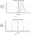
- FIG. 2 shows field curvature curves of the telephoto lens 10 in this embodiment
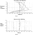
- FIG. 3 shows axial spherical aberration curves of the telephoto lens 10 in this embodiment
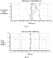
- FIG. 4 shows lateral chromatic aberration curves of the telephoto lens 10 in this embodiment.
- the field curvature, the axial spherical aberration, the lateral chromatic aberration and the distortion of the telephoto lens 10 of this embodiment are all corrected well.
- FIG.5 is a structural diagram of a telephoto lens 20 provided in this embodiment.
- the telephoto lens 20 in this embodiment is substantially similar to the telephoto lens 10 in the first embodiment expect that: a second lens L2 of the telephoto lens 20 has a negative refractive power, an object side surface S3 of the second lens L2 and an image side surface S4 of the second lens L2 are both aspheric surface, and the radius of curvature and the materials of each lens are different. Related parameters of each lens are shown in Table 3. Table 3 Surface NO.
- Table 4 Surface NO. k A 4 A 6 A 8 A 10 A 12 A 14 A 16 S1 -0.416 2.77E-05 1.31E-05 -1.46E-06 1.10E-07 -6.10E-09 1.20E-10 -8.29E-13 S2 0.000 1.67E-03 -6.09E-05 -2.20E-07 8.60E-09 0.00E+00 0.00E+00 S3 9.782 2.24E-03 -1.30E-05 0.00E+00 0.00E+00 0.00E+00 0.00E+00 S4 1.954 -1.64E-04 9.74E-05 0.00E+00 0.00E+00 0.00E+00 0.00E+00 0.00E+00 0.00E+00 0.00E+00 0.00E+00 0.00E+00
- FIG. 6 shows field curvature curves of the telephoto lens 20 in this embodiment
- FIG. 7 shows axial spherical aberration of the telephoto lens 20 in this embodiment
- FIG. 8 shows lateral chromatic aberration curves of the telephoto lens 20 in this embodiment.
- the field curvature, the axial spherical aberration, the lateral chromatic aberration, and the distortion of the telephoto lens 20 of this embodiment are all corrected well.
- FIG. 9 is a structural diagram of a telephoto lens 30 provided in this embodiment.
- the telephoto lens 30 in this embodiment is substantially similar to the telephoto lens 10 in the first embodiment expect that: a first lens L1 and a second lens L2 of the telephoto lens 30 form a cemented lens, the second lens L2 has a negative refractive power, and the radius of curvature and the materials of each lens are different. Related parameters of each lens are shown in Table 5. Table 5 Surface NO.
- Table 6 Surface NO. k A 4 A 6 A 8 A 10 A 12 A 14 A 16 S1 -0.197 -5.81E-05 1.08E-05 -1.68E-06 1.42E-07 -6.81E-09 1.72E-10 -1.76E-12
- FIG. 10 shows field curvature curves of the telephoto lens 30 in this embodiment
- FIG. 11 shows axial spherical aberration of the telephoto lens 30 in this embodiment
- FIG. 12 shows lateral chromatic aberration curves of the lateral chromatic aberration of the telephoto lens 30 in this embodiment.
- the field curvature, the axial spherical aberration, the lateral chromatic aberration and the distortion of the telephoto lens 30 of this embodiment are all corrected well.
- FIG. 13 is a structural diagram of a telephoto lens 40 provided in this embodiment.
- the telephoto lens 40 in this embodiment is substantially similar to the telephoto lens 10 in the first embodiment expect that: an image side surface of a second lens L2 of the telephoto lens 40 is a convex surface, and the radius of curvature and the materials of each lens are different. Related parameters of each lens are shown in Table 7. Table 7 Surface NO.
- Table 8 Surface NO. k A 4 A 6 A 8 A 10 A 12 A 14 A 16 S1 -0.685 1.56E-04 -4.92E-06 1.08E-07 1.20E-08 -1.50E-09 5.86E-11 -1.39E-12 S2 1.454 7.57E-05 -1.06E-05 3.36E-07 7.07E-09 -1.24E-09 1.12E-11 0.00E+00
- FIG. 14 shows field curvature curves of the telephoto lens 40 in this embodiment
- FIG. 15 shows axial spherical aberration of the telephoto lens 40 in this embodiment
- FIG. 16 shows lateral chromatic aberration curves of the telephoto lens 40 in this embodiment.
- the field curvature, the axial spherical aberration, the lateral chromatic aberration and the distortion of the telephoto lens 40 of this embodiment are all corrected well.
- Table 9 shows the optical characteristics corresponding to the telephoto lens in the above four embodiments, including the total optical length TTL, the focal length f, the aperture number F #, and the field angle 2 ⁇ , and the value corresponding to each of the above conditional expression.
- Table 9 Condition First embodiment Second embodiment Third embodiment Fourth embodiment TTL 34.045 34.093 33.950 34.075 f 31.000 31.000 31.004 31.000 F# 3.6 3.6 3.6 3.6 2 ⁇ 8° 8° 8° 8° TTL / f 1.098 1.100 1.095 1.099 f / R 1 4.348 3.976 4.117 4.221 R 1 / R 6 1.354 1.367 1.429 1.352 CT 2 / CT 1 1.035 0.261 0.224 0.517 f 2 lf 1 0.677 -3.037 -3.196 3.929 f 3 / f -0.481 -0.886 -0.565 -0.473 ( R 3 + R 4 ) /( R 3 - R 4 )
- the total optical length of the telephoto lens provided by the disclosure exceeds 30mm, which is far more than the thickness of a mobile phone.
- the lens can be designed as a periscope lens imaging system using a reflective optical surface, which is embedded in the mobile phone to the meet the requirements of thin and light electronics product.
- the equivalent focal length of a conventional wide-angle lens is usually 20 ⁇ 30mm.
- the equivalent focal length ratio of the two is more than 8 times, that is, the telephoto lens provided by the disclosure can achieve zooming of more than 8 times when used in combination with the conventional wide-angle lens, thereby having better zoom imaging effects and better satisfying the requirements of miniaturization and high-definition imaging of electronic products.
- the embodiment provides a mobile terminal 100 including an image sensor 50 and a telephoto lens in any of the foregoing embodiments, such as the telephoto lens 10.
- the image sensor 50 is disposed on the imaging surface S11 of the telephoto lens 10, and configured to receive optical signals output by the telephoto lens and form electrical signals corresponding to the optical signals.
- the image sensor 50 may be a Complementary Metal Oxide Semiconductor (CMOS) image sensor, or a Charge Coupled Device (CCD) image sensor.
- CMOS Complementary Metal Oxide Semiconductor
- CCD Charge Coupled Device
- the total optical length TTL of the telephoto lens provided by the disclosure can reach 34mm, which is far more than the thickness of the mobile terminal 100.
- the mobile terminal 100 further includes a first prism 61 and a second prism 62.
- the first prism 61 is disposed at an entrance of the telephoto lens
- the second prism 62 is disposed at an exit of the telephoto lens 10, thereby designing the telephoto lens 10 as a periscope lens imaging system (the incident light and the exit light are perpendicular to different planes) using reflective optical surfaces of the prisms, shortening a transmission distance of the optical path, and meeting the miniaturization requirements of the mobile terminal 100.
- the first prism 61 turns the incident light (incident parallel to the paper surface) into the telephoto lens 10
- the second prism 62 turns the light emitted by the telephoto lens 10 again to form the exit light (exit perpendicular to the paper surface), the incident light and the exit light form a vertical relationship.
- the mobile terminal 100 provided by the embodiment includes the telephoto lens 10, which can achieve a higher zoom ratio than a conventional telephoto lens, and can better satisfy the requirements of miniaturization and high-definition imaging of electronic products.
Landscapes
- Physics & Mathematics (AREA)
- General Physics & Mathematics (AREA)
- Optics & Photonics (AREA)
- Engineering & Computer Science (AREA)
- Signal Processing (AREA)
- Multimedia (AREA)
- Lenses (AREA)
Abstract
Description
- The present disclosure relates to the field of optical lens technologies, and more particularly, to a telephoto lens and a mobile terminal.
- In recent years, with the pursuit of the imaging quality of portable electronic products, dual cameras have become the standard equipment for mobile phone products. In order to achieve high-quality imaging effect, most mobile phones use a solution of "fixed-focus dual-camera", which is a combination of a wide-angle lens and a telephoto lens, therefore the mobile phone can not only perform wide-angle shooting, but also enlarge the scene clearly when shooting in the distance, so that the mobile phone can have a good shooting effect similar to that of signal lens reflex cameras.
- In the conventional dual-camera products, the equivalent focal length ratio of the telephoto lens and the wide-angle lens is between 3 and 5 times, and the zoom ratio can reach 3 to 5 times when the two are used in combination. The zoom ratio is too small compared with the traditional zoom lens, so it is difficult to meet the requirements of miniaturization and high-definition imaging of portable electronic products.
- The objects of the disclosure are to provide a telephoto lens and a mobile terminal to solve the above problems.
- The embodiments of the present disclosure achieve the above objects through the following technical solutions.
- In a first aspect, the present disclosure provides a telephoto lens. From an object side to an imaging surface, the telephoto lens sequentially includes: a first lens having a positive refractive power, a second lens having a refractive power, a third lens having a negative refractive power, a flat glass and a filter. An object side surface of the first lens is a convex surface, an image side surface of the third lens is a concave surface.
- In a second aspect, the present disclosure provides a mobile terminal. The mobile terminal includes a telephoto lens and an image sensor, the image sensor is disposed on an imaging surface of the telephoto lens and configured to receive optical signals output by the telephoto lens and form electrical signals corresponding to the optical signals.
- Compared with the related art, the telephoto lens and the mobile terminal provided by the disclosure can achieve a higher zoom ratio. The equivalent focal length of the telephoto lens provided by the disclosure and the conventional wide-angle lens is more than 8 times, that is, the telephoto lens provided by the disclosure can achieve zooming of more than 8 times when used in combination with the conventional wide-angle lens, thereby better satisfying the requirements of miniaturization and high-definition imaging of electronic products.
- The advantages of the present disclosure will be partially given in the following description, and some will become apparent from the following description, or be learned through the practice of the present disclosure.
-
-
FIG. 1 is a schematic structural diagram of a telephoto lens in a first embodiment of the disclosure. -
FIG. 2 is a diagram showing field curvature curves of the telephoto lens in the first embodiment of the disclosure. -
FIG. 3 is a diagram showing axial spherical aberration curves of the telephoto lens in the first embodiment of the disclosure. -
FIG. 4 is a diagram showing lateral chromatic aberration curves of the telephoto lens in the first embodiment of the disclosure. -
FIG. 5 is a schematic structural diagram of a telephoto lens in a second embodiment of the disclosure. -
FIG. 6 is a diagram showing field curvature curves of the telephoto lens in the second embodiment of the disclosure. -
FIG. 7 is a diagram showing axial spherical aberration curves of the telephoto lens in the second embodiment of the disclosure. -
FIG. 8 is a diagram showing lateral chromatic aberration curves of the telephoto lens in the second embodiment of the disclosure. -
FIG. 9 is a schematic structural diagram of a telephoto lens in a third embodiment of the disclosure. -
FIG. 10 is a diagram showing field curvature curves of the telephoto lens in the third embodiment of the disclosure. -
FIG. 11 is a diagram showing axial spherical aberration curves of the telephoto lens in the third embodiment of the disclosure. -
FIG. 12 is a diagram showing lateral chromatic aberration curves of the telephoto lens in the third embodiment of the disclosure. -
FIG. 13 is a schematic structural diagram of a telephoto lens in a fourth embodiment of the disclosure. -
FIG. 14 is a diagram showing field curvature curves of the telephoto lens in the fourth embodiment of the disclosure. -
FIG. 15 is a diagram showing axial spherical aberration curves of the telephoto lens in the fourth embodiment of the disclosure. -
FIG. 16 is a diagram showing lateral chromatic aberration curves of the telephoto lens in the fourth embodiment of the disclosure. -
FIG. 17 is a schematic structural diagram of a mobile terminal in a fifth embodiment of the disclosure. -
FIG. 18 is a top view of theFIG. 17 . - Reference numerals of main components:
Stop ST First lens L1 Second lens L2 Third lens L3 Flat glass G1 Filter G2 - The following embodiments will further illustrate the present disclosure with reference to the above drawings.
- In order to facilitate a better understanding of the present disclosure, the present disclosure will be further explained below with reference to the accompanying drawings. The embodiments of the present disclosure are shown in the drawings, but the present disclosure is not limited to the above-mentioned preferred embodiments. Rather, these embodiments are provided to make the disclosure of the present disclosure more sufficient.
- The embodiment of the present disclosure provides a telephoto lens. Form an object side to an imaging surface, the telephoto lens sequentially includes: a first lens having a positive refractive power, a second lens having a refractive power, a third lens having a negative refractive power, a flat glass, and a filter. An object side surface of the first lens is a convex surface, an image side surface of the third lens is a concave surface.
- In some embodiments, the telephoto lens meets the expression: 0.75 < TTL/f < 2.0;
where TTL represents a total optical lens of the telephoto lens, f represents a focal length of the telephoto lens. Satisfying the above expression can effectively shorten the total optical length of the telephoto lens and promote the miniaturization of the telephoto lens. - In some embodiments, the flat glass meets the expression: Nd4 > 1.8;
where Nd4 refers to a refractive index of the flat glass. The flat glass uses a material with high refractive index to facilitate the incidence of the light. - In some embodiments, the first lens is made of glass. Due to the temperature resistance of the glass material is better and the performance is more stable, the first lens is made of glass material, which can effectively achieve the effect of thermalization for the telephoto lens.
- In some embodiments, the telephoto lens meets the expression: 3 < f/R 1 < 5;
where f represents a focal length of the telephoto lens, R 1 represents a radius of curvature of the object side surface of the first lens. When the value of f/R 1 exceeds the lower limit, the refractive power of the first lens becomes larger, which is not conducive to ensuring the peripheral performance, and the eccentric sensitivity becomes larger. When the value of f/R 1 exceeds the upper limit, it is difficult to correct the chromatic aberration of the telephoto lens. - In some embodiments, the telephoto lens meets the expression: 1 < R 1/ R 6 < 2;
where R 1 represents a radius of curvature of the object side surface of the first lens, R 6 represents a radius of curvature of the image side surface of the third lens. Satisfying the above expression can effectively improve the resolution of the margin field of the telephoto lens. - In some embodiments, the telephoto lens meets the expression: 0 < CT 2/CT 1 , < 2;
where CT 1 represents a center thickness of the first lens, CT 2 represents a center thickness of the second lens. Satisfying the above expression can effectively shorten the total optical length of the telephoto lens and promote the miniaturization of the telephoto lens. - In some embodiments, the telephoto lens meets the expression: -5<f 2/f 1 < 5;
where f 1 represents a focal length of the first lens, f 2 represents a focal length of the second lens. When the value of f/R 1 exceeds the lower limit, the refractive power and the eccentric sensitivity becomes larger; when the value of f/R 1 exceeds the upper limit, the refractive power becomes smaller, which is not conducive to maintaining miniaturization. - In some embodiments, the telephoto lens meets the expression: -1< f 3/f< 0;
where f 3 represents a focal length of the third lens, f represents a focal length of the telephoto lens. When the value of f 3 lf exceeds the lower limit, high-order aberration will occur for off-axis lights, and the performance of the telephoto will deteriorate; when the value of f 3/f exceeds the upper limit, it is relatively difficult to correct the field curvature and the coma, and the eccentric sensitivity becomes larger. - In some embodiments, the telephoto lens meets the expression: -2 < (R 3 + R 4)/(R 3 - R 4) < 5;
where R 3 represents a radius of curvature of the object side surface of the second lens, R 4 represents a radius of curvature of the image side surface of the second lens. When the value of (R 3 + R 4)/(R 3 - R 4) exceeds the upper limit, the field curvature and the distortion increase excessively in the positive direction, and are difficult to correct. Conversely, when the value of (R 3 + R 4)/(R 3 - R 4) exceeds the lower limit, the field curvature and the distortion increase excessively in the negative direction, and also are difficult to correct. - In some embodiments, the telephoto lens meets the expression: -2 < R 4/f 2 < 3;
where R 4 represents a radius of curvature of the image side surface of the second lens, f 2 represents a focal length of the second lens. When the value of R 4/f 2 exceeds the lower limit, the refractive power of R 4 becomes larger, which is not conducive to ensure the peripheral performance, and the eccentric sensitivity becomes larger; when the value of R 4/ f 2 exceeds the upper limit, it is difficult to correct the field curvature. - In some embodiments, at least one of the object side surface of the first lens, an image side surface of the first lens, an object side surface of the second lens, an image side surface of the second lens, an object side surface of the third lens, and the image side surface of the third lens is a aspheric surface. A stop is disposed between the object side and the first lens. Aspheric surface can make the telephoto lens have more control variables to reduce aberration.
- The embodiment of the present disclosure further provides a mobile terminal. The mobile terminal includes the telephoto lens as mentioned in any above embodiments, the mobile terminal further includes an image sensor, the image sensor is disposed on the imaging surface of the telephoto lens and configured to receive optical signals output by the telephoto lens and form electrical signals corresponding to the optical signals.
- The shapes of aspheric surfaces of the optical lens provided by the embodiments of the present disclosure satisfy the following equation:

- Compared with a conventional telephoto lens, the telephoto lens provided by the present disclosure can achieve a higher zoom ratio. The zoom ratio refers to the ratio of the equivalent focal length of the telephoto lens to the equivalent focal length of the wide-angle lens under the premise of the same pixels. Equivalent focal length = actual focal length * focal length conversion factor; focal length conversion factor = 43.3 / the diagonal length of the target surface of the image sensor.
- The equivalent focal length of the telephoto lens provided by the disclosure and the conventional wide-angle lens is more than 8 times, that is, the telephoto lens provided by the disclosure can achieve zooming of more than 8 times when used in combination with the conventional wide-angle lens, thereby better satisfying the requirements of miniaturization and high-definition imaging of electronic products.
- The present disclosure will be further described in the following multiple embodiments. In each of the following embodiments, the thickness and radius of curvature of each lens in the telephoto lens are different. For specific differences, refer to the parameter table in each embodiment.
- Please refer to
FIG.1 , which is a structural diagram of atelephoto lens 10 provided in a first embodiment of the disclosure. From an object side to an imaging surface thereof, thetelephoto lens 10 sequentially includes a stop ST, a first lens L1, a second lens L2, a third lens L3, a flat glass G1 and a filter G2. - The first lens L1 has a positive refractive power, an object side surface S1 of the first lens L1 is a convex surface and an image side surface S2 of the first lens L1 is a concave surface. The first lens is made of glass, and the object side surface S1 of the first lens L1 and the image side surface S2 of the first lens L1 are both aspheric surfaces. The second lens L2 has a positive refractive power, an object side surface S3 of the second lens L2 is a convex surface, an image side surface S4 of the second lens L2 is a concave surface. The third lens L3 has a negative refractive power, an object side surface S5 of the third lens L3 is a convex surface, an image side surface S6 of the third lens L3 is a concave surface.
- Related parameters of each lens in the
telephoto lens 10 provided by the first lens are shown in Table 1.Table 1 Surface NO. Sign Surface type Radius of curvature Thickness Refractive index Abbe number Object surface S0 Flat surface - ST Stop Flat surface - -1.498 S1 First lens L1 Aspheric surface 7.130 1.317 1.808 40.921 S2 Aspheric surface 9.529 0.139 S3 Second lens L2 Spherical surface 10.321 1.363 1.697 56.200 S4 Spherical surface 44.119 0.048 S5 Third lens L3 Spherical surface 9.711 0.497 1.805 25.477 S6 Spherical surface 5.265 10.000 S7 Flat glass G1 Flat surface - 13.000 1.901 37.054 S8 Flat surface - 0.200 S9 Filter G2 Flat surface - 0.210 1.517 64.212 S10 Flat surface - 7.272 S11 Imaging surface Flat surface - - - The parameters of the aspheric surfaces of the first lens of this embodiment are shown in Table 2.
Table 2 Surface NO. k A4 A6 A8 A10 A12 A14 A16 S1 -0.399 1.70E-05 3.53E-06 -1.21E-06 1.13E-07 -6.39E-09 1.87E-10 -2.38 E-12 S2 0 7.18E-07 -4.44E-06 -1.18E-07 -3.40E-09 2.77E-10 -1.33E-11 0.00E+00 -
FIG. 2 shows field curvature curves of thetelephoto lens 10 in this embodiment,FIG. 3 shows axial spherical aberration curves of thetelephoto lens 10 in this embodiment,FIG. 4 shows lateral chromatic aberration curves of thetelephoto lens 10 in this embodiment. As can be seen from the figures, the field curvature, the axial spherical aberration, the lateral chromatic aberration and the distortion of thetelephoto lens 10 of this embodiment are all corrected well. - Please refer to
FIG.5 , which is a structural diagram of atelephoto lens 20 provided in this embodiment. Thetelephoto lens 20 in this embodiment is substantially similar to thetelephoto lens 10 in the first embodiment expect that: a second lens L2 of thetelephoto lens 20 has a negative refractive power, an object side surface S3 of the second lens L2 and an image side surface S4 of the second lens L2 are both aspheric surface, and the radius of curvature and the materials of each lens are different. Related parameters of each lens are shown in Table 3.Table 3 Surface NO. Sign Surface type Radius of curvature Thickness Refractive index Abbe number Object surface S0 Flat surface - ST Stop Flat surface - -1.345 S1 First lens L1 Aspheric surface 7.796 1.711 1.773 49.503 S2 Aspheric surface 43.597 0.041 S3 Second lens L2 Aspheric surface 15.694 0.446 1.544 55.951 S4 Aspheric surface 8.683 0.541 S5 Third lens L3 Spherical surface 7.595 0.488 1.946 17.944 S6 Spherical surface 5.705 10.000 S7 Flat glass G1 Flat surface - 13.000 1.901 37.054 S8 Flat surface - 0.200 S9 Filter G2 Flat surface - 0.210 1.517 64.212 S10 Flat surface - 7.456 S11 Imaging surface Flat surface - - - The parameters of the aspheric surfaces of the lenses of this embodiment are shown in Table 4.
Table 4 Surface NO. k A4 A6 A8 A10 A12 A14 A16 S1 -0.416 2.77E-05 1.31E-05 -1.46E-06 1.10E-07 -6.10E-09 1.20E-10 -8.29E-13 S2 0.000 1.67E-03 -6.09E-05 -2.20E-07 8.60E-09 0.00E+00 0.00E+00 0.00E+00 S3 9.782 2.24E-03 -1.30E-05 0.00E+00 0.00E+00 0.00E+00 0.00E+00 0.00E+00 S4 1.954 -1.64E-04 9.74E-05 0.00E+00 0.00E+00 0.00E+00 0.00E+00 0.00E+00 -
FIG. 6 shows field curvature curves of thetelephoto lens 20 in this embodiment,FIG. 7 shows axial spherical aberration of thetelephoto lens 20 in this embodiment,FIG. 8 shows lateral chromatic aberration curves of thetelephoto lens 20 in this embodiment. As can be seen from the figures, the field curvature, the axial spherical aberration, the lateral chromatic aberration, and the distortion of thetelephoto lens 20 of this embodiment are all corrected well. - Please refer to
FIG. 9 , which is a structural diagram of atelephoto lens 30 provided in this embodiment. Thetelephoto lens 30 in this embodiment is substantially similar to thetelephoto lens 10 in the first embodiment expect that: a first lens L1 and a second lens L2 of thetelephoto lens 30 form a cemented lens, the second lens L2 has a negative refractive power, and the radius of curvature and the materials of each lens are different. Related parameters of each lens are shown in Table 5.Table 5 Surface NO. Sign Surface type Radius of curvature Thickness Refractive index Abbe number Object surface S0 Flat surface - ST Stop Flat surface - -1.462 S1 First lens L1 Aspheric surface 7.530 2.023 1.773 49.503 S2 Second lens L2 Spherical surface 39.522 0.441 1.648 33.842 S3 Spherical surface 23.101 0.452 S4 Third lens L3 Spherical surface 8.710 0.471 1.805 25.477 S5 Spherical surface 5.270 10.000 S6 Flat glass G1 Flat surface - 13.000 1.901 37.054 S7 Flat surface - 0.200 S8 Filter G2 Flat surface - 0.210 1.517 64.212 S9 Flat surface - 7.153 S10 Imaging surface Flat surface - - - The parameters of the aspheric surfaces of the lenses of this embodiment are shown in Table 6.
Table 6 Surface NO. k A4 A6 A8 A10 A12 A14 A16 S1 -0.197 -5.81E-05 1.08E-05 -1.68E-06 1.42E-07 -6.81E-09 1.72E-10 -1.76E-12 -
FIG. 10 shows field curvature curves of thetelephoto lens 30 in this embodiment,FIG. 11 shows axial spherical aberration of thetelephoto lens 30 in this embodiment,FIG. 12 shows lateral chromatic aberration curves of the lateral chromatic aberration of thetelephoto lens 30 in this embodiment. As can be seen from the figures, the field curvature, the axial spherical aberration, the lateral chromatic aberration and the distortion of thetelephoto lens 30 of this embodiment are all corrected well. - Please refer to
FIG. 13 , which is a structural diagram of atelephoto lens 40 provided in this embodiment. Thetelephoto lens 40 in this embodiment is substantially similar to thetelephoto lens 10 in the first embodiment expect that: an image side surface of a second lens L2 of thetelephoto lens 40 is a convex surface, and the radius of curvature and the materials of each lens are different. Related parameters of each lens are shown in Table 7.Table 7 Surface NO. Sign Surface type Radius of curvature Thickness Refractive index Abbe number Object surface S0 Flat surface - ST Stop Flat surface - -1.462 S1 First lens L1 Aspheric surface 7.344 1.746 1.768 49.647 S2 Aspheric surface 19.649 0.327 S3 Second lens L2 Spherical surface 48.985 0.902 1.603 65.460 S4 Spherical surface -110.657 0.046 S5 Third lens L3 Spherical surface 11.239 0.509 1.741 27.762 S6 Spherical surface 5.432 10.000 S7 Flat glass G1 Flat surface - 13.000 1.901 37.054 S8 Flat surface - 0.200 S9 Filter G2 Flat surface - 0.210 1.517 64.212 S10 Flat surface - 7.134 S11 Imaging surface Flat surface - - - The parameters of the aspheric surfaces of the lenses of this embodiment are shown in Table 8.
Table 8 Surface NO. k A4 A6 A8 A10 A12 A14 A16 S1 -0.685 1.56E-04 -4.92E-06 1.08E-07 1.20E-08 -1.50E-09 5.86E-11 -1.39E-12 S2 1.454 7.57E-05 -1.06E-05 3.36E-07 7.07E-09 -1.24E-09 1.12E-11 0.00E+00 -
FIG. 14 shows field curvature curves of thetelephoto lens 40 in this embodiment,FIG. 15 shows axial spherical aberration of thetelephoto lens 40 in this embodiment,FIG. 16 shows lateral chromatic aberration curves of thetelephoto lens 40 in this embodiment. As can be seen from the figures, the field curvature, the axial spherical aberration, the lateral chromatic aberration and the distortion of thetelephoto lens 40 of this embodiment are all corrected well. - Table 9 shows the optical characteristics corresponding to the telephoto lens in the above four embodiments, including the total optical length TTL, the focal length f, the aperture number F #, and the field angle 2θ, and the value corresponding to each of the above conditional expression.
Table 9 Condition First embodiment Second embodiment Third embodiment Fourth embodiment TTL 34.045 34.093 33.950 34.075 f 31.000 31.000 31.004 31.000 F# 3.6 3.6 3.6 3.6 2θ 8° 8° 8° 8° TTL/f 1.098 1.100 1.095 1.099 f/R 1 4.348 3.976 4.117 4.221 R 1/R 6 1.354 1.367 1.429 1.352 CT 2/CT 1 1.035 0.261 0.224 0.517 f 2 lf 1 0.677 -3.037 -3.196 3.929 f 3/f -0.481 -0.886 -0.565 -0.473 (R 3 + R 4 )/(R 3 - R 4) -1.611 3.477 3.814 -0.386 R 4/f 2 2.327 -0.238 -0.724 -1.966 - The total optical length of the telephoto lens provided by the disclosure exceeds 30mm, which is far more than the thickness of a mobile phone. When the telephoto lens is used in a mobile phone, the lens can be designed as a periscope lens imaging system using a reflective optical surface, which is embedded in the mobile phone to the meet the requirements of thin and light electronics product.
- The focal lens of the telephoto lens provided by the disclosure can reach 31mm, and the diagonal length of the image sensor matched with the telephoto lens is 5mm, and the calculation method of the equivalent focal length can be obtained: (1) focal length conversion factor = 43.3 / the diagonal length of the target surface of the image sensor = 43.3 / 5 = 8.66; (2) equivalent focal length = actual focal length * focal length conversion factor = 31 * 8.66 = 268.46mm. Therefore, the equivalent focal length of the telephoto lens provided by the disclosure can reach 268mm. Generally, the equivalent focal length of a conventional wide-angle lens is usually 20 ~ 30mm. When the telephoto lens provided by the disclosure is used in combination with a conventional wide-angle lens, the equivalent focal length ratio of the two is more than 8 times, that is, the telephoto lens provided by the disclosure can achieve zooming of more than 8 times when used in combination with the conventional wide-angle lens, thereby having better zoom imaging effects and better satisfying the requirements of miniaturization and high-definition imaging of electronic products.
- Please refer to
FIG. 17 and FIG. 18 , the embodiment provides amobile terminal 100 including animage sensor 50 and a telephoto lens in any of the foregoing embodiments, such as thetelephoto lens 10. Theimage sensor 50 is disposed on the imaging surface S11 of thetelephoto lens 10, and configured to receive optical signals output by the telephoto lens and form electrical signals corresponding to the optical signals. - The
image sensor 50 may be a Complementary Metal Oxide Semiconductor (CMOS) image sensor, or a Charge Coupled Device (CCD) image sensor. - The total optical length TTL of the telephoto lens provided by the disclosure can reach 34mm, which is far more than the thickness of the
mobile terminal 100. When thetelephoto lens 10 is disposed in themobile terminal 100, themobile terminal 100 further includes afirst prism 61 and asecond prism 62. Thefirst prism 61 is disposed at an entrance of the telephoto lens, and thesecond prism 62 is disposed at an exit of thetelephoto lens 10, thereby designing thetelephoto lens 10 as a periscope lens imaging system (the incident light and the exit light are perpendicular to different planes) using reflective optical surfaces of the prisms, shortening a transmission distance of the optical path, and meeting the miniaturization requirements of themobile terminal 100. - As shown in the perspective of
FIG. 17 , thefirst prism 61 turns the incident light (incident parallel to the paper surface) into thetelephoto lens 10, and thesecond prism 62 turns the light emitted by thetelephoto lens 10 again to form the exit light (exit perpendicular to the paper surface), the incident light and the exit light form a vertical relationship. - The
mobile terminal 100 provided by the embodiment includes thetelephoto lens 10, which can achieve a higher zoom ratio than a conventional telephoto lens, and can better satisfy the requirements of miniaturization and high-definition imaging of electronic products. - The above-mentioned embodiments are merely illustrative of several embodiments of the present disclosure, and the description thereof is more specific and detailed, however is not to be construed as limiting the scope of the disclosure. It should be noted that various variations and modifications may be made by those skilled in the art without departing from the spirit and scope of the disclosure. Therefore, the scope of the disclosure should be determined by the appended claims.
Claims (14)
- A telephoto lens, from an object side to an imaging surface thereof, sequentially comprising:a first lens having a positive refractive power, an object side surface of the first lens being convex;a second lens having a refractive power;a third lens having a negative refractive power, an image side surface of the third lens being concave;a flat glass; anda filter.
- The telephoto lens as claimed in claim 1, wherein the telephoto lens meets the expression:

- The telephoto lens as claimed in claim 1, wherein the flat glass meets the expression:

- The telephoto lens as claimed in claim 1, wherein the first lens is made of glass.
- The telephoto lens as claimed in claim 1, wherein the telephoto lens meets the expression:

- The telephoto lens as claimed in claim 1, wherein the telephoto lens meets the expression:

- The telephoto lens as claimed in claim 1, wherein the telephoto lens meets the expression:

- The telephoto lens as claimed in claim 1, wherein the telephoto lens meets the expression:

- The telephoto lens as claimed in claim 1, wherein the telephoto lens meets the expression:

- The telephoto lens as claimed in claim 1, wherein the telephoto lens meets the expression:

- The telephoto lens as claimed in claim 1, wherein the telephoto lens meets the expression:

- The telephoto lens as claimed in claim 1, wherein at least one of the object side surface of the first lens, an image side surface of the first lens, an object side surface of the second lens, an image side surface of the second lens, an object side surface of the third lens, and the image side surface of the third lens is a aspheric surface; and a stop is disposed between the object side and the first lens.
- A mobile terminal, comprising a telephoto lens as claimed in any one of claims 1-12 and an image sensor, the image sensor is disposed on an imaging surface of the telephoto lens and configured to receive optical signals output by the telephoto lens and form electrical signals corresponding to the optical signals.
- The mobile terminal as claimed in claim 13, wherein the mobile terminal further comprises a first prism and a second prism, the first prism is disposed at an entrance of the telephoto lens, the second prism is disposed at an exit of the telephoto lens, the first prism turns incident lights into the telephoto lens, and the second prism turns the lights again to form exit lights, the incident lights and the exit lights are perpendicular.
Applications Claiming Priority (2)
| Application Number | Priority Date | Filing Date | Title |
|---|---|---|---|
| CN201910005847.1A CN109557643B (en) | 2019-01-03 | 2019-01-03 | Telephoto lens and mobile terminal |
| PCT/CN2019/127517 WO2020140788A1 (en) | 2019-01-03 | 2019-12-23 | Telephoto lens and mobile terminal |
Publications (3)
| Publication Number | Publication Date |
|---|---|
| EP3876019A1 true EP3876019A1 (en) | 2021-09-08 |
| EP3876019A4 EP3876019A4 (en) | 2022-01-12 |
| EP3876019B1 EP3876019B1 (en) | 2025-08-13 |
Family
ID=65872360
Family Applications (1)
| Application Number | Title | Priority Date | Filing Date |
|---|---|---|---|
| EP19906814.9A Active EP3876019B1 (en) | 2019-01-03 | 2019-12-23 | Telephoto lens and mobile terminal |
Country Status (4)
| Country | Link |
|---|---|
| US (1) | US11340428B2 (en) |
| EP (1) | EP3876019B1 (en) |
| CN (1) | CN109557643B (en) |
| WO (1) | WO2020140788A1 (en) |
Families Citing this family (9)
| Publication number | Priority date | Publication date | Assignee | Title |
|---|---|---|---|---|
| CN109557643B (en) * | 2019-01-03 | 2020-06-23 | 江西联益光学有限公司 | Telephoto lens and mobile terminal |
| CN110058389B (en) * | 2019-05-30 | 2024-04-09 | 浙江舜宇光学有限公司 | Combined zoom double-shot lens |
| US12196917B2 (en) * | 2019-06-28 | 2025-01-14 | Jiangxi Jingchao Optical Co., Ltd. | Imaging lens, photographing module, and electronic device |
| TWI719659B (en) | 2019-10-03 | 2021-02-21 | 大立光電股份有限公司 | Imaging optical system, imaging apparatus and electronic device |
| CN111929859B (en) * | 2020-09-22 | 2021-04-02 | 江西联益光学有限公司 | Telephoto lens and mobile terminal |
| CN115701117B (en) | 2021-07-29 | 2025-09-05 | 华为技术有限公司 | Camera modules and electronic equipment |
| CN114200642B (en) * | 2021-11-17 | 2022-11-08 | 珠海视熙科技有限公司 | Lens system, imaging module and camera |
| KR102724907B1 (en) * | 2022-11-24 | 2024-11-01 | 삼성전기주식회사 | Imaging Lens System |
| US12411320B2 (en) | 2022-11-24 | 2025-09-09 | Samsung Electro-Mechanics Co., Ltd. | Imaging lens system |
Family Cites Families (17)
| Publication number | Priority date | Publication date | Assignee | Title |
|---|---|---|---|---|
| JP4631306B2 (en) * | 2004-04-26 | 2011-02-16 | 株式会社ニコン | Objective lens and observation optical system |
| DE602005003905T2 (en) * | 2004-11-01 | 2008-12-11 | Konica Minolta Opto, Inc., Hachioji | Compact lens with three single lenses |
| JP5013078B2 (en) * | 2007-04-24 | 2012-08-29 | コニカミノルタアドバンストレイヤー株式会社 | Lens barrel and imaging device |
| CN201145765Y (en) * | 2007-12-06 | 2008-11-05 | 新鉅科技股份有限公司 | Imaging lens group |
| JP5952135B2 (en) * | 2012-08-28 | 2016-07-13 | カンタツ株式会社 | Ultra-small imaging lens |
| JP6146741B2 (en) * | 2013-07-29 | 2017-06-14 | 株式会社オプトロジック | Imaging lens |
| JP6237106B2 (en) * | 2013-10-18 | 2017-11-29 | コニカミノルタ株式会社 | Zoom lens and imaging device |
| TWI522645B (en) * | 2015-01-05 | 2016-02-21 | 信泰光學(深圳)有限公司 | Lens assembly |
| CN104977699B (en) * | 2015-06-30 | 2017-08-01 | 瑞声声学科技(苏州)有限公司 | Pick-up lens |
| CN204833031U (en) | 2015-07-10 | 2015-12-02 | 灿瑞半导体(上海)有限公司 | A compensating circuit for adjusting charging device's output voltage |
| CN204883031U (en) * | 2015-08-11 | 2015-12-16 | 浙江舜宇光学有限公司 | Modular zoom |
| TWI627438B (en) * | 2015-11-12 | 2018-06-21 | 柯尼卡美能達股份有限公司 | Lens unit, image capture device, and mobile device |
| KR102732412B1 (en) * | 2016-07-29 | 2024-11-22 | 삼성전자주식회사 | Optical lens assembly and electronic apparatus having the same |
| CN206387955U (en) * | 2016-12-12 | 2017-08-08 | 广西师范大学 | A kind of compact high-pixel mobile phone lens |
| CN109557643B (en) * | 2019-01-03 | 2020-06-23 | 江西联益光学有限公司 | Telephoto lens and mobile terminal |
| TWI719659B (en) * | 2019-10-03 | 2021-02-21 | 大立光電股份有限公司 | Imaging optical system, imaging apparatus and electronic device |
| TWI757732B (en) * | 2020-05-05 | 2022-03-11 | 大立光電股份有限公司 | Image capturing optical lens assembly, imaging apparatus and electronic device |
-
2019
- 2019-01-03 CN CN201910005847.1A patent/CN109557643B/en active Active
- 2019-12-23 WO PCT/CN2019/127517 patent/WO2020140788A1/en not_active Ceased
- 2019-12-23 EP EP19906814.9A patent/EP3876019B1/en active Active
-
2020
- 2020-07-02 US US16/920,362 patent/US11340428B2/en active Active
Also Published As
| Publication number | Publication date |
|---|---|
| US11340428B2 (en) | 2022-05-24 |
| EP3876019A4 (en) | 2022-01-12 |
| EP3876019B1 (en) | 2025-08-13 |
| CN109557643A (en) | 2019-04-02 |
| WO2020140788A1 (en) | 2020-07-09 |
| CN109557643B (en) | 2020-06-23 |
| US20200333561A1 (en) | 2020-10-22 |
Similar Documents
| Publication | Publication Date | Title |
|---|---|---|
| EP3876019B1 (en) | Telephoto lens and mobile terminal | |
| US20210055519A1 (en) | Lens group, camera module and motion camera | |
| US12270972B2 (en) | Optical lens, camera module and terminal | |
| US12092796B2 (en) | Optical imaging lens assembly | |
| US20210055528A1 (en) | Wide-angle lens, camera module and camera | |
| US7821724B2 (en) | Photographing optical lens assembly | |
| EP3904934A1 (en) | Optical system, camera module, and electronic apparatus | |
| EP3896510A1 (en) | Optical system, image capturing device and electronic device | |
| US20180045923A1 (en) | Telephoto lens | |
| EP3876020A1 (en) | Optical imaging lens and imaging device | |
| US12124006B2 (en) | Camera lens group | |
| EP4170407A1 (en) | Seven-lens imaging objective | |
| EP4194921A1 (en) | Optical system, lens module, and electronic device | |
| CN114114650B (en) | Optical lens and imaging apparatus | |
| US11531186B2 (en) | Electronic imaging device comprising two capturing devices | |
| CN111239971A (en) | Optical system, camera module and electronic device | |
| CN113433674B (en) | Optical lens and imaging apparatus | |
| CN113721345B (en) | Optical system, lens module and electronic equipment | |
| CN112014957B (en) | Optical lens and imaging apparatus | |
| WO2022222926A1 (en) | Optical lens and imaging device | |
| EP4435488A1 (en) | Optical imaging system, camera module and electronic device | |
| CN113741006A (en) | Optical lens, camera module and electronic equipment | |
| EP4682608A2 (en) | Optical lens, image module, and terminal device | |
| US20210389569A1 (en) | Six-piece optical lens system with a wide field of view | |
| CN113253429B (en) | Wide-angle lens and imaging apparatus |
Legal Events
| Date | Code | Title | Description |
|---|---|---|---|
| STAA | Information on the status of an ep patent application or granted ep patent |
Free format text: STATUS: THE INTERNATIONAL PUBLICATION HAS BEEN MADE |
|
| PUAI | Public reference made under article 153(3) epc to a published international application that has entered the european phase |
Free format text: ORIGINAL CODE: 0009012 |
|
| STAA | Information on the status of an ep patent application or granted ep patent |
Free format text: STATUS: REQUEST FOR EXAMINATION WAS MADE |
|
| 17P | Request for examination filed |
Effective date: 20210603 |
|
| AK | Designated contracting states |
Kind code of ref document: A1 Designated state(s): AL AT BE BG CH CY CZ DE DK EE ES FI FR GB GR HR HU IE IS IT LI LT LU LV MC MK MT NL NO PL PT RO RS SE SI SK SM TR |
|
| STAA | Information on the status of an ep patent application or granted ep patent |
Free format text: STATUS: EXAMINATION IS IN PROGRESS |
|
| A4 | Supplementary search report drawn up and despatched |
Effective date: 20211214 |
|
| RIC1 | Information provided on ipc code assigned before grant |
Ipc: H04M 1/02 20060101ALI20211208BHEP Ipc: G02B 13/00 20060101ALI20211208BHEP Ipc: G02B 9/12 20060101ALI20211208BHEP Ipc: G02B 13/02 20060101AFI20211208BHEP |
|
| 17Q | First examination report despatched |
Effective date: 20220105 |
|
| DAV | Request for validation of the european patent (deleted) | ||
| DAX | Request for extension of the european patent (deleted) | ||
| GRAP | Despatch of communication of intention to grant a patent |
Free format text: ORIGINAL CODE: EPIDOSNIGR1 |
|
| STAA | Information on the status of an ep patent application or granted ep patent |
Free format text: STATUS: GRANT OF PATENT IS INTENDED |
|
| INTG | Intention to grant announced |
Effective date: 20250528 |
|
| GRAS | Grant fee paid |
Free format text: ORIGINAL CODE: EPIDOSNIGR3 |
|
| GRAA | (expected) grant |
Free format text: ORIGINAL CODE: 0009210 |
|
| STAA | Information on the status of an ep patent application or granted ep patent |
Free format text: STATUS: THE PATENT HAS BEEN GRANTED |
|
| AK | Designated contracting states |
Kind code of ref document: B1 Designated state(s): AL AT BE BG CH CY CZ DE DK EE ES FI FR GB GR HR HU IE IS IT LI LT LU LV MC MK MT NL NO PL PT RO RS SE SI SK SM TR |
|
| REG | Reference to a national code |
Ref country code: GB Ref legal event code: FG4D |
|
| REG | Reference to a national code |
Ref country code: CH Ref legal event code: EP |
|
| REG | Reference to a national code |
Ref country code: DE Ref legal event code: R096 Ref document number: 602019074240 Country of ref document: DE |
|
| REG | Reference to a national code |
Ref country code: IE Ref legal event code: FG4D |
|
| REG | Reference to a national code |
Ref country code: NL Ref legal event code: MP Effective date: 20250813 |
|
| PG25 | Lapsed in a contracting state [announced via postgrant information from national office to epo] |
Ref country code: IS Free format text: LAPSE BECAUSE OF FAILURE TO SUBMIT A TRANSLATION OF THE DESCRIPTION OR TO PAY THE FEE WITHIN THE PRESCRIBED TIME-LIMIT Effective date: 20251213 |
|
| PG25 | Lapsed in a contracting state [announced via postgrant information from national office to epo] |
Ref country code: NO Free format text: LAPSE BECAUSE OF FAILURE TO SUBMIT A TRANSLATION OF THE DESCRIPTION OR TO PAY THE FEE WITHIN THE PRESCRIBED TIME-LIMIT Effective date: 20251113 |
|
| REG | Reference to a national code |
Ref country code: LT Ref legal event code: MG9D |
|
| PG25 | Lapsed in a contracting state [announced via postgrant information from national office to epo] |
Ref country code: PT Free format text: LAPSE BECAUSE OF FAILURE TO SUBMIT A TRANSLATION OF THE DESCRIPTION OR TO PAY THE FEE WITHIN THE PRESCRIBED TIME-LIMIT Effective date: 20251215 |
|
| PG25 | Lapsed in a contracting state [announced via postgrant information from national office to epo] |
Ref country code: FI Free format text: LAPSE BECAUSE OF FAILURE TO SUBMIT A TRANSLATION OF THE DESCRIPTION OR TO PAY THE FEE WITHIN THE PRESCRIBED TIME-LIMIT Effective date: 20250813 |
|
| PG25 | Lapsed in a contracting state [announced via postgrant information from national office to epo] |
Ref country code: NL Free format text: LAPSE BECAUSE OF FAILURE TO SUBMIT A TRANSLATION OF THE DESCRIPTION OR TO PAY THE FEE WITHIN THE PRESCRIBED TIME-LIMIT Effective date: 20250813 Ref country code: HR Free format text: LAPSE BECAUSE OF FAILURE TO SUBMIT A TRANSLATION OF THE DESCRIPTION OR TO PAY THE FEE WITHIN THE PRESCRIBED TIME-LIMIT Effective date: 20250813 |
|
| PG25 | Lapsed in a contracting state [announced via postgrant information from national office to epo] |
Ref country code: GR Free format text: LAPSE BECAUSE OF FAILURE TO SUBMIT A TRANSLATION OF THE DESCRIPTION OR TO PAY THE FEE WITHIN THE PRESCRIBED TIME-LIMIT Effective date: 20251114 |
|
| PG25 | Lapsed in a contracting state [announced via postgrant information from national office to epo] |
Ref country code: SE Free format text: LAPSE BECAUSE OF FAILURE TO SUBMIT A TRANSLATION OF THE DESCRIPTION OR TO PAY THE FEE WITHIN THE PRESCRIBED TIME-LIMIT Effective date: 20250813 |
|
| PG25 | Lapsed in a contracting state [announced via postgrant information from national office to epo] |
Ref country code: LV Free format text: LAPSE BECAUSE OF FAILURE TO SUBMIT A TRANSLATION OF THE DESCRIPTION OR TO PAY THE FEE WITHIN THE PRESCRIBED TIME-LIMIT Effective date: 20250813 |
|
| PG25 | Lapsed in a contracting state [announced via postgrant information from national office to epo] |
Ref country code: PL Free format text: LAPSE BECAUSE OF FAILURE TO SUBMIT A TRANSLATION OF THE DESCRIPTION OR TO PAY THE FEE WITHIN THE PRESCRIBED TIME-LIMIT Effective date: 20250813 Ref country code: BG Free format text: LAPSE BECAUSE OF FAILURE TO SUBMIT A TRANSLATION OF THE DESCRIPTION OR TO PAY THE FEE WITHIN THE PRESCRIBED TIME-LIMIT Effective date: 20250813 |
|
| PG25 | Lapsed in a contracting state [announced via postgrant information from national office to epo] |
Ref country code: RS Free format text: LAPSE BECAUSE OF FAILURE TO SUBMIT A TRANSLATION OF THE DESCRIPTION OR TO PAY THE FEE WITHIN THE PRESCRIBED TIME-LIMIT Effective date: 20251113 |
|
| PG25 | Lapsed in a contracting state [announced via postgrant information from national office to epo] |
Ref country code: ES Free format text: LAPSE BECAUSE OF FAILURE TO SUBMIT A TRANSLATION OF THE DESCRIPTION OR TO PAY THE FEE WITHIN THE PRESCRIBED TIME-LIMIT Effective date: 20250813 |
|
| REG | Reference to a national code |
Ref country code: AT Ref legal event code: MK05 Ref document number: 1825279 Country of ref document: AT Kind code of ref document: T Effective date: 20250813 |
|
| PG25 | Lapsed in a contracting state [announced via postgrant information from national office to epo] |
Ref country code: RO Free format text: LAPSE BECAUSE OF FAILURE TO SUBMIT A TRANSLATION OF THE DESCRIPTION OR TO PAY THE FEE WITHIN THE PRESCRIBED TIME-LIMIT Effective date: 20250813 |
|
| PG25 | Lapsed in a contracting state [announced via postgrant information from national office to epo] |
Ref country code: SM Free format text: LAPSE BECAUSE OF FAILURE TO SUBMIT A TRANSLATION OF THE DESCRIPTION OR TO PAY THE FEE WITHIN THE PRESCRIBED TIME-LIMIT Effective date: 20250813 |
|
| PG25 | Lapsed in a contracting state [announced via postgrant information from national office to epo] |
Ref country code: DK Free format text: LAPSE BECAUSE OF FAILURE TO SUBMIT A TRANSLATION OF THE DESCRIPTION OR TO PAY THE FEE WITHIN THE PRESCRIBED TIME-LIMIT Effective date: 20250813 |
|
| PGFP | Annual fee paid to national office [announced via postgrant information from national office to epo] |
Ref country code: DE Payment date: 20260127 Year of fee payment: 7 |
|
| PG25 | Lapsed in a contracting state [announced via postgrant information from national office to epo] |
Ref country code: AT Free format text: LAPSE BECAUSE OF FAILURE TO SUBMIT A TRANSLATION OF THE DESCRIPTION OR TO PAY THE FEE WITHIN THE PRESCRIBED TIME-LIMIT Effective date: 20250813 |
|
| PG25 | Lapsed in a contracting state [announced via postgrant information from national office to epo] |
Ref country code: IT Free format text: LAPSE BECAUSE OF FAILURE TO SUBMIT A TRANSLATION OF THE DESCRIPTION OR TO PAY THE FEE WITHIN THE PRESCRIBED TIME-LIMIT Effective date: 20250813 |
|
| PG25 | Lapsed in a contracting state [announced via postgrant information from national office to epo] |
Ref country code: CZ Free format text: LAPSE BECAUSE OF FAILURE TO SUBMIT A TRANSLATION OF THE DESCRIPTION OR TO PAY THE FEE WITHIN THE PRESCRIBED TIME-LIMIT Effective date: 20250813 |
|
| PG25 | Lapsed in a contracting state [announced via postgrant information from national office to epo] |
Ref country code: EE Free format text: LAPSE BECAUSE OF FAILURE TO SUBMIT A TRANSLATION OF THE DESCRIPTION OR TO PAY THE FEE WITHIN THE PRESCRIBED TIME-LIMIT Effective date: 20250813 Ref country code: SK Free format text: LAPSE BECAUSE OF FAILURE TO SUBMIT A TRANSLATION OF THE DESCRIPTION OR TO PAY THE FEE WITHIN THE PRESCRIBED TIME-LIMIT Effective date: 20250813 |
|
| REG | Reference to a national code |
Ref country code: DE Ref legal event code: R097 Ref document number: 602019074240 Country of ref document: DE |
|
| PLBE | No opposition filed within time limit |
Free format text: ORIGINAL CODE: 0009261 |
|
| STAA | Information on the status of an ep patent application or granted ep patent |
Free format text: STATUS: NO OPPOSITION FILED WITHIN TIME LIMIT |
|
| REG | Reference to a national code |
Ref country code: CH Ref legal event code: L10 Free format text: ST27 STATUS EVENT CODE: U-0-0-L10-L00 (AS PROVIDED BY THE NATIONAL OFFICE) Effective date: 20260624 |
|
| PG25 | Lapsed in a contracting state [announced via postgrant information from national office to epo] |
Ref country code: LT Free format text: LAPSE BECAUSE OF FAILURE TO SUBMIT A TRANSLATION OF THE DESCRIPTION OR TO PAY THE FEE WITHIN THE PRESCRIBED TIME-LIMIT Effective date: 20250813 |
|
| PG25 | Lapsed in a contracting state [announced via postgrant information from national office to epo] |
Ref country code: MC Free format text: LAPSE BECAUSE OF FAILURE TO SUBMIT A TRANSLATION OF THE DESCRIPTION OR TO PAY THE FEE WITHIN THE PRESCRIBED TIME-LIMIT Effective date: 20250813 |
|
| 26N | No opposition filed |
Effective date: 20260515 |
|
| REG | Reference to a national code |
Ref country code: CH Ref legal event code: H13 Free format text: ST27 STATUS EVENT CODE: U-0-0-H10-H13 (AS PROVIDED BY THE NATIONAL OFFICE) Effective date: 20260723 |