EP3875875A1 - A cooling appliance having an icemaker - Google Patents
A cooling appliance having an icemaker Download PDFInfo
- Publication number
- EP3875875A1 EP3875875A1 EP20186378.4A EP20186378A EP3875875A1 EP 3875875 A1 EP3875875 A1 EP 3875875A1 EP 20186378 A EP20186378 A EP 20186378A EP 3875875 A1 EP3875875 A1 EP 3875875A1
- Authority
- EP
- European Patent Office
- Prior art keywords
- water
- ice maker
- pipe
- damper
- cooling appliance
- Prior art date
- Legal status (The legal status is an assumption and is not a legal conclusion. Google has not performed a legal analysis and makes no representation as to the accuracy of the status listed.)
- Granted
Links
Images


Classifications
-
- F—MECHANICAL ENGINEERING; LIGHTING; HEATING; WEAPONS; BLASTING
- F25—REFRIGERATION OR COOLING; COMBINED HEATING AND REFRIGERATION SYSTEMS; HEAT PUMP SYSTEMS; MANUFACTURE OR STORAGE OF ICE; LIQUEFACTION SOLIDIFICATION OF GASES
- F25C—PRODUCING, WORKING OR HANDLING ICE
- F25C1/00—Producing ice
- F25C1/22—Construction of moulds; Filling devices for moulds
- F25C1/25—Filling devices for moulds
-
- F—MECHANICAL ENGINEERING; LIGHTING; HEATING; WEAPONS; BLASTING
- F25—REFRIGERATION OR COOLING; COMBINED HEATING AND REFRIGERATION SYSTEMS; HEAT PUMP SYSTEMS; MANUFACTURE OR STORAGE OF ICE; LIQUEFACTION SOLIDIFICATION OF GASES
- F25C—PRODUCING, WORKING OR HANDLING ICE
- F25C2400/00—Auxiliary features or devices for producing, working or handling ice
- F25C2400/12—Means for sanitation
-
- F—MECHANICAL ENGINEERING; LIGHTING; HEATING; WEAPONS; BLASTING
- F25—REFRIGERATION OR COOLING; COMBINED HEATING AND REFRIGERATION SYSTEMS; HEAT PUMP SYSTEMS; MANUFACTURE OR STORAGE OF ICE; LIQUEFACTION SOLIDIFICATION OF GASES
- F25C—PRODUCING, WORKING OR HANDLING ICE
- F25C2500/00—Problems to be solved
- F25C2500/06—Spillage or flooding of water
Definitions
- the present invention relates to a cooling appliance, in particular to a cooling appliance having an ice maker wherein the ice maker comprises a water damper to damp the flow of the water.
- the modern cooling appliances are provided with automatic ice makers.
- the ice makers are provided with a pipe to supply water to the ice maker.
- the said ice makers are filled with water and after a certain amount of time, the ice maker is bent via a motor and the newly formed ice cubes are ejected from the ice maker.
- the cooling appliance keeps forming and storing ice cubes until a predetermined level of ice is obtained. Due to the automatic structure such ice making systems have, the users have limited possibilities of intervention. As a result of this, as the water is filled inside the ice maker, some of the water overflows or splashes forming ice near or on the ice maker. This causes malfunctions and physical damage to the ice maker.
- a prior art publication in the technical field of the present invention may be referred to as WO2014084506A1 others, the document disclosing a cooling appliance having an ice maker and an ice transfer means.
- An objective of the present invention is to provide a cooling appliance having an ice maker and a water damper to prevent overflow of water.
- the method realized to achieve the aim of the present invention and disclosed in the first claim and the dependent claims comprises a cooling appliance having an ice maker.
- the ice maker is placed inside the freezing compartment or inside the fresh food compartment and is isolated from fresh food compartment so as to keep the surrounding temperature of the ice maker below zero.
- the ice maker is placed on to the rear surface of a door of the cooling appliance.
- a pipe is positioned above the ice maker and supplies water to the ice maker.
- a water damper is placed above the ice maker and is configured to guide and damp the water supplied by the pipe.
- the water damper is in conical shape with its diameter gradually decreasing from top to bottom meaning that towards the ice maker.
- a guide is provided in the form of a protrusion on the inner surface the ice maker.
- the guide forms a spiral in a first direction which helps forming a vortex in the first direction.
- the area of the opening is substantially smaller than the area of the cover.
- the water damper is made of an elastic material.
- the water damper is collapsible reversible upon being pushed on. It reverses in vertical direction. After the water damper is reversed so as to be inside out, the guide remains outside the water damper.
- the guide is symmetrical with respect to the water damper, therefore forming a secondary guide inside the water damper and the spiral shape. This time the spiral shape of the guide is in a second direction opposite to the first direction.
- the user may use the same water damper to efficiently damp the water both in northern and southern hemisphere.
- a heater is coiled around the pipe so as to prevent blockage of the pipe by gradual formation of the ice inside the pipe.
- the pipe comprises an outlet wherein the outlet is at least partly placed inside the cover via the opening.
- the extension direction of the outlet is bent with respect to the extension direction of the pipe.
- the outlet comprises a bottleneck wherein the cross sectional area of the outlet decreases.
- the water is slowed down and dispersed which in turn helps to prevent overflow.
- the ice maker is provided with the water damper that helps guide the flow of water inside via the guide, preventing the overflow of water.
- the present invention relates to a cooling appliance (1) comprising; an ice maker (2) configured to generate ice cubes, a pipe (3) to supply water to the ice maker (2), a water damper (4) positioned above the ice maker (2) to receive the water from the pipe (3) and wherein the water damper (4) has a conical shape with a diameter gradually decreasing from top to the bottom.
- the present invention relates to the cooling appliance (1) further comprising a guide (5) in the form of a protrusion forming a spiral in a first direction extending in the vertical direction on the inner surface of the water damper (4) guiding the flow of the water to flow at least partially along itself.
- the cooling appliance (1) of the present invention comprises the ice maker (2).
- the ice maker (2) is placed inside the freezing compartment of the cooling appliance (1) wherein the inner temperature of the freezing compartment is below freezing point of water. It is equally possible that the ice maker (2) may be located inside the fresh food compartment. In such case, the ice maker is isolated from the fresh food compartment via a plurality of walls so as to keep temperature in close vicinity of the ice maker below zero.
- the ice maker (2) may be located on the rear surface of a door of the cooling appliance (1).
- the water is supplied to the ice maker (2) via the pipe (3).
- the pipe (3) is connected to a reservoir provided inside or in close vicinity of the cooling appliance (1) or directly to a main.
- the water damper (4) is positioned above the ice maker (2) and is configured to damp and guide the flow of the water as the water from the pipe (3) flows inside the water damper (4).
- the water damper (4) is in conical shape with the diameter decreasing towards the ice maker (2). Therefore, the water passes through the pipe (3), the water damper (4) and reaches the ice maker (2) respectively.
- the conical shape the water damper (4) has helps reduce the splash of the water as the water emerges from the pipe (3) and contacts the water damper (4).
- the water damper (4) comprises the guide (5) on the inner surface of the water damper (4).
- the guide (5) is in the form of a protrusion and forms the spiral inside the water damper in the first direction.
- the water flows at least partly along the guide (5) therefore creating a vortex which in turn helps the water flow and reduce the splash of water outside the water damper (4).
- the water damper (4) and the guide (5) the water is prevented to splash which helps reduce accumulation of water and therefore that of the ice near or in close vicinity of the ice maker (2) which causes malfunction of the ice maker (2) in the long run. Therefore, easier operation of the ice maker (2) is provided for the user.
- the cooling appliance (1) comprises a cover (6) removably placed onto the water damper (4) wherein the cover (6) comprises an opening (7) provided thereon through which the pipe (3) is seated.
- the cover (6) is concave shaped and protrudes upwards.
- the cover (6) comprises the opening (7) through which the pipe (3) is partly inserted.
- the opening provides the pipe (3) to be seated in between the cover (6) and the opening (7).
- the cover (7) further helps to eliminate the splash of water and therefore, accumulation of ice near or in close vicinity of the ice maker (2).
- the area of the opening (7) is substantially smaller than the area of the cover (6).
- the area covered by the opening (7) is smaller than the area covered by the cover (6) which helps to minimize the risk of ice accumulation near or in close vicinity of the ice maker (2).
- the water damper (4) is removably placed above the ice maker (2) and that the water damper (4) is made of an elastic material and that the water damper (4) is collapsible reversible along the vertical direction which upon being reversed can be placed above the ice maker (2) changing the direction of the spiral to a second direction opposite to the first direction.
- the water damper (4) is made of an elastic material such as silicone or similar.
- the water damper (4) can be removed from its place and is configured to be collapsible reversible and put back into the place so as to be positioned above the ice maker (2). Upon reversing the water damper (4), the guide (5) will also be reversed.
- the guide (5) is configured to remain inside the water damper (4) in the form of a protrusion forming a spiral in the second direction extending in the vertical direction on the inner surface of the water damper (4) guiding the flow of the water to flow at least partially along itself.
- the guide (5) forms a spiral in the first direction corresponding to the counter clockwise direction.
- the technicians or the user may revers the water damper (4) in the southern hemisphere, therefore changing the direction of the spiral to the second direction corresponding to the clockwise direction.
- the water damper (4) can be efficiently used for both norther hemisphere and southern hemisphere meanwhile minimizing the splash of water.
- the cooling appliance (1) comprises a heater (8) coiling around the pipe (3).
- the heater (8) coils around the pipe (3) preventing formation of ice inside the pipe (3) which in turn will cause the ice maker (2) to malfunction.
- the pipe (3) comprises an outlet (9) via which the pipe (3) is seated through the opening (8) and wherein the outlet (9) is configured to bend with respect to an extension direction of the pipe (3).
- the extension direction of the outlet (9) and the extension direction of the pipe (3) forms an angle in between.
- the outlet (9) comprises a bottleneck.
- the bottleneck is used for slowing down and dispersing the water flowing through the pipe (3). This helps minimize the amount of water overflowing the water damper (4).
- the cooling appliance (1) is provided with the ice maker (2) and the water damper (4) to be used with the ice maker (2) wherein the water damper (4) is in conical shape to damp and guide the water therefore preventing overflow of water which in turn causes formation of ice.
- Another advantageous effect provided thanks to the reversible collapsible structure the water damper (4) has is that the water damper (4) can be efficiently used both in northern and southern hemisphere.
Landscapes
- Engineering & Computer Science (AREA)
- Physics & Mathematics (AREA)
- Mechanical Engineering (AREA)
- Thermal Sciences (AREA)
- General Engineering & Computer Science (AREA)
- Devices That Are Associated With Refrigeration Equipment (AREA)
Abstract
Description
- The present invention relates to a cooling appliance, in particular to a cooling appliance having an ice maker wherein the ice maker comprises a water damper to damp the flow of the water.
- The modern cooling appliances are provided with automatic ice makers. The ice makers are provided with a pipe to supply water to the ice maker. The said ice makers are filled with water and after a certain amount of time, the ice maker is bent via a motor and the newly formed ice cubes are ejected from the ice maker. The cooling appliance keeps forming and storing ice cubes until a predetermined level of ice is obtained. Due to the automatic structure such ice making systems have, the users have limited possibilities of intervention. As a result of this, as the water is filled inside the ice maker, some of the water overflows or splashes forming ice near or on the ice maker. This causes malfunctions and physical damage to the ice maker.
- A prior art publication in the technical field of the present invention may be referred to as
US2019128595A1 among others, the document disclosing a cooling appliance having an automatic ice maker. - A prior art publication in the technical field of the present invention may be referred to as
WO2014084506A1 others, the document disclosing a cooling appliance having an ice maker and an ice transfer means. - An objective of the present invention is to provide a cooling appliance having an ice maker and a water damper to prevent overflow of water.
- The method realized to achieve the aim of the present invention and disclosed in the first claim and the dependent claims comprises a cooling appliance having an ice maker. The ice maker is placed inside the freezing compartment or inside the fresh food compartment and is isolated from fresh food compartment so as to keep the surrounding temperature of the ice maker below zero. In a preferred embodiment, the ice maker is placed on to the rear surface of a door of the cooling appliance. A pipe is positioned above the ice maker and supplies water to the ice maker. A water damper is placed above the ice maker and is configured to guide and damp the water supplied by the pipe. The water damper is in conical shape with its diameter gradually decreasing from top to bottom meaning that towards the ice maker. A guide is provided in the form of a protrusion on the inner surface the ice maker. The guide forms a spiral in a first direction which helps forming a vortex in the first direction. The helps to prevent the overflow of the water being poured inside the water damper. By this means, the water is prevented to overflow the water damper which in time will accumulate in the form of ice on or in close vicinity of the ice maker. The formation of ice causes the ice maker to malfunction.
- In an embodiment of the invention, a cover is removably placed on to the water damper. The cover is concave shaped and protrudes upwards. The cover comprises an opening through which the pipe passes through. By means of the cover, the overflow of water is further minimized.
- In an embodiment of the invention, the area of the opening is substantially smaller than the area of the cover. By means of the opening being substantially smaller than the cover, the pipe after passing through the opening, almost no gap remains in between the pipe and the cover.
- In an embodiment of the invention, the water damper is made of an elastic material. The water damper is collapsible reversible upon being pushed on. It reverses in vertical direction. After the water damper is reversed so as to be inside out, the guide remains outside the water damper. The guide is symmetrical with respect to the water damper, therefore forming a secondary guide inside the water damper and the spiral shape. This time the spiral shape of the guide is in a second direction opposite to the first direction. By this means, the user may use the same water damper to efficiently damp the water both in northern and southern hemisphere.
- In an embodiment of the invention, a heater is coiled around the pipe so as to prevent blockage of the pipe by gradual formation of the ice inside the pipe.
- In an embodiment of the invention, the pipe comprises an outlet wherein the outlet is at least partly placed inside the cover via the opening. The extension direction of the outlet is bent with respect to the extension direction of the pipe. By this means, the water is diverted towards the water damper and to the guide.
- In an embodiment of the invention, the outlet comprises a bottleneck wherein the cross sectional area of the outlet decreases. By means of the bottleneck, the water is slowed down and dispersed which in turn helps to prevent overflow.
- In the cooling appliance of the present invention, the ice maker is provided with the water damper that helps guide the flow of water inside via the guide, preventing the overflow of water.
- The drawings are not meant to delimit the scope of protection as identified in the claims nor should they be referred to alone in an effort to interpret the scope identified in the claims without recourse to the technical disclosure in the description of the present invention.
-
Figure 1 - is a front view of the cooling appliance -
Figure 2 - is an isolated view of the door of the cooling appliance -
Figure 3 - is a cross sectinal view of the door along the dashed line A-A inFigure 2 -
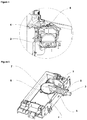
Figure 4 - is an enlarged view of the dashed line B-B inFigure 3 -
Figure 5 - is an isolated view of the ice maker in connection with the water damper - The following numerals are assigned to different parts demonstrated in the drawings and referred to in the present detailed description of the invention:
- 1. Cooling appliance
- 2. Ice maker
- 3. Pipe
- 4. Water damper
- 5. Guide
- 6. Cover
- 7. Opening
- 8. Heater
- 9. Outlet
- The present invention relates to a cooling appliance (1) comprising; an ice maker (2) configured to generate ice cubes, a pipe (3) to supply water to the ice maker (2), a water damper (4) positioned above the ice maker (2) to receive the water from the pipe (3) and wherein the water damper (4) has a conical shape with a diameter gradually decreasing from top to the bottom.
- The present invention relates to the cooling appliance (1) further comprising a guide (5) in the form of a protrusion forming a spiral in a first direction extending in the vertical direction on the inner surface of the water damper (4) guiding the flow of the water to flow at least partially along itself. The cooling appliance (1) of the present invention comprises the ice maker (2). The ice maker (2) is placed inside the freezing compartment of the cooling appliance (1) wherein the inner temperature of the freezing compartment is below freezing point of water. It is equally possible that the ice maker (2) may be located inside the fresh food compartment. In such case, the ice maker is isolated from the fresh food compartment via a plurality of walls so as to keep temperature in close vicinity of the ice maker below zero. It is also equally possible that the ice maker (2) may be located on the rear surface of a door of the cooling appliance (1). The water is supplied to the ice maker (2) via the pipe (3). The pipe (3) is connected to a reservoir provided inside or in close vicinity of the cooling appliance (1) or directly to a main. The water damper (4) is positioned above the ice maker (2) and is configured to damp and guide the flow of the water as the water from the pipe (3) flows inside the water damper (4). The water damper (4) is in conical shape with the diameter decreasing towards the ice maker (2). Therefore, the water passes through the pipe (3), the water damper (4) and reaches the ice maker (2) respectively. The conical shape the water damper (4) has helps reduce the splash of the water as the water emerges from the pipe (3) and contacts the water damper (4). The water damper (4) comprises the guide (5) on the inner surface of the water damper (4). The guide (5) is in the form of a protrusion and forms the spiral inside the water damper in the first direction. The water flows at least partly along the guide (5) therefore creating a vortex which in turn helps the water flow and reduce the splash of water outside the water damper (4). By means of the water damper (4) and the guide (5) the water is prevented to splash which helps reduce accumulation of water and therefore that of the ice near or in close vicinity of the ice maker (2) which causes malfunction of the ice maker (2) in the long run. Therefore, easier operation of the ice maker (2) is provided for the user.
- In an embodiment, the cooling appliance (1) comprises a cover (6) removably placed onto the water damper (4) wherein the cover (6) comprises an opening (7) provided thereon through which the pipe (3) is seated. The cover (6) is concave shaped and protrudes upwards. The cover (6) comprises the opening (7) through which the pipe (3) is partly inserted. By means of the cover (6), the water is prevented to overflow the water damper (4) helping reduce the unwanted formation of ice in close vicinity or near the ice maker (2). The opening on the other hand provides the pipe (3) to be seated in between the cover (6) and the opening (7). The cover (7) further helps to eliminate the splash of water and therefore, accumulation of ice near or in close vicinity of the ice maker (2).
- In a preferred embodiment the area of the opening (7) is substantially smaller than the area of the cover (6). The area covered by the opening (7) is smaller than the area covered by the cover (6) which helps to minimize the risk of ice accumulation near or in close vicinity of the ice maker (2).
- In a preferred embodiment the water damper (4) is removably placed above the ice maker (2) and that the water damper (4) is made of an elastic material and that the water damper (4) is collapsible reversible along the vertical direction which upon being reversed can be placed above the ice maker (2) changing the direction of the spiral to a second direction opposite to the first direction. The water damper (4) is made of an elastic material such as silicone or similar. The water damper (4) can be removed from its place and is configured to be collapsible reversible and put back into the place so as to be positioned above the ice maker (2). Upon reversing the water damper (4), the guide (5) will also be reversed. In such case the guide (5) is configured to remain inside the water damper (4) in the form of a protrusion forming a spiral in the second direction extending in the vertical direction on the inner surface of the water damper (4) guiding the flow of the water to flow at least partially along itself. As the water flows, it tends to form a vortex in counter clockwise direction in the norther hemisphere. The guide (5) forms a spiral in the first direction corresponding to the counter clockwise direction. Likewise, the technicians or the user may revers the water damper (4) in the southern hemisphere, therefore changing the direction of the spiral to the second direction corresponding to the clockwise direction. By this means, the water damper (4) can be efficiently used for both norther hemisphere and southern hemisphere meanwhile minimizing the splash of water.
- In a preferred embodiment the cooling appliance (1) comprises a heater (8) coiling around the pipe (3). The heater (8) coils around the pipe (3) preventing formation of ice inside the pipe (3) which in turn will cause the ice maker (2) to malfunction.
- In a preferred embodiment the pipe (3) comprises an outlet (9) via which the pipe (3) is seated through the opening (8) and wherein the outlet (9) is configured to bend with respect to an extension direction of the pipe (3). The extension direction of the outlet (9) and the extension direction of the pipe (3) forms an angle in between. By this means the outlet (9), water is directed towards the inner volume of the water damper (4). This helps minimize the amount of water overflowing the water damper (4).
- In a preferred embodiment the outlet (9) comprises a bottleneck. The bottleneck is used for slowing down and dispersing the water flowing through the pipe (3). This helps minimize the amount of water overflowing the water damper (4).
- In the cooling appliance (1) of the present invention, the cooling appliance (1) is provided with the ice maker (2) and the water damper (4) to be used with the ice maker (2) wherein the water damper (4) is in conical shape to damp and guide the water therefore preventing overflow of water which in turn causes formation of ice. Another advantageous effect provided thanks to the reversible collapsible structure the water damper (4) has is that the water damper (4) can be efficiently used both in northern and southern hemisphere.
Claims (7)
- A cooling appliance (1) comprising;
An ice maker (2) configured to generate ice cubes,
A pipe (3) to supply water to the ice maker (2),
a water damper (4) positioned above the ice maker (2) to receive the water from the pipe (3) and wherein the water damper (4) has a conical shape with a diameter gradually decreasing from top to the bottom,
characterized by a guide (5) in the form of a protrusion forming a spiral in a first direction extending in the vertical direction on the inner surface of the water damper (4) guiding the flow of the water to flow at least partially along itself. - A cooling appliance (1) according to claim 1, characterized by a cover (6) removably placed onto the water damper (4) wherein the cover (6) comprises an opening (7) provided thereon through which the pipe (3) is seated.
- A cooling appliance (1) according to claim 2, characterized in that the area of the opening (7) is substantially smaller than the area of the cover (6).
- A cooling appliance (1) according to any of the preceeding claims, characterized in that the water damper (4) is removably placed above the ice maker (2) and that the water damper (4) is made of an elastic material and that the water damper (4) is collapsible reversible along the vertical direction which upon being reversed can be placed above the ice maker (2) changing the direction of the spiral to a second direction opposite to the first direction.
- A cooling appliance (1) according to any of the preceeding claims, characterized by a heater (8) coiling around the pipe (3).
- A cooling appliance (1) according to claims 2 to 5, characterized in that the pipe (3) comprises an outlet (9) via which the pipe (3) is seated through the opening (8) and wherein the outlet (9) is configured to bend with respect to an extension direction of the pipe (3).
- A cooling appliance (1) according to claim 6, characterized in that the outlet (9) comprises a bottleneck.
Applications Claiming Priority (1)
| Application Number | Priority Date | Filing Date | Title |
|---|---|---|---|
| TR201909984 | 2019-07-04 |
Publications (2)
| Publication Number | Publication Date |
|---|---|
| EP3875875A1 true EP3875875A1 (en) | 2021-09-08 |
| EP3875875B1 EP3875875B1 (en) | 2023-12-13 |
Family
ID=71670059
Family Applications (1)
| Application Number | Title | Priority Date | Filing Date |
|---|---|---|---|
| EP20186378.4A Active EP3875875B1 (en) | 2019-07-04 | 2020-07-17 | A cooling appliance having an icemaker |
Country Status (2)
| Country | Link |
|---|---|
| EP (1) | EP3875875B1 (en) |
| PL (1) | PL3875875T3 (en) |
Citations (3)
| Publication number | Priority date | Publication date | Assignee | Title |
|---|---|---|---|---|
| WO2014084506A1 (en) | 2012-11-30 | 2014-06-05 | 주식회사 에코에너지 기술연구소 | Ice maker |
| US8800315B2 (en) * | 2010-07-14 | 2014-08-12 | Lg Electronics Inc. | Refrigerator |
| US20190128595A1 (en) | 2017-10-31 | 2019-05-02 | Hisense Ronshen (Guangdong) Refrigerator Co., Ltd. | Water-feed assembly of ice maker in refrigerator and refrigerator |
Family Cites Families (2)
| Publication number | Priority date | Publication date | Assignee | Title |
|---|---|---|---|---|
| KR20050093762A (en) * | 2003-02-12 | 2005-09-23 | 가부시끼가이샤 도시바 | Purification device and refrigerator using the same |
| KR101564263B1 (en) * | 2010-07-08 | 2015-10-30 | 엘지전자 주식회사 | Heating system for hot water and water purifier having the same |
-
2020
- 2020-07-17 EP EP20186378.4A patent/EP3875875B1/en active Active
- 2020-07-17 PL PL20186378.4T patent/PL3875875T3/en unknown
Patent Citations (3)
| Publication number | Priority date | Publication date | Assignee | Title |
|---|---|---|---|---|
| US8800315B2 (en) * | 2010-07-14 | 2014-08-12 | Lg Electronics Inc. | Refrigerator |
| WO2014084506A1 (en) | 2012-11-30 | 2014-06-05 | 주식회사 에코에너지 기술연구소 | Ice maker |
| US20190128595A1 (en) | 2017-10-31 | 2019-05-02 | Hisense Ronshen (Guangdong) Refrigerator Co., Ltd. | Water-feed assembly of ice maker in refrigerator and refrigerator |
Also Published As
| Publication number | Publication date |
|---|---|
| PL3875875T3 (en) | 2024-04-29 |
| EP3875875B1 (en) | 2023-12-13 |
Similar Documents
| Publication | Publication Date | Title |
|---|---|---|
| KR102306723B1 (en) | beverage supply | |
| EP2993274B1 (en) | Wc with low noise | |
| CA1081980A (en) | Beverage cooling bath | |
| EP3875875B1 (en) | A cooling appliance having an icemaker | |
| EP2453194A1 (en) | Drain provided with a heat exchanger, and shower tray or shower cubicle provided with such a drain | |
| WO2018061307A1 (en) | Fryer | |
| KR101281590B1 (en) | Ice discharing amount control structure for ice container | |
| JP2017030828A (en) | Beverage dispenser | |
| KR20150134158A (en) | drinking water supplying device | |
| JP5056293B2 (en) | Main water heater system | |
| JP2017165445A (en) | Beverage dispenser | |
| KR102548269B1 (en) | Water purifying apparatus | |
| CN212619513U (en) | Ice making machine | |
| JP5294966B2 (en) | Ice machine drainage structure | |
| JPH0422310A (en) | electric water heater | |
| JP5254084B2 (en) | Ice machine drainage structure | |
| KR20260028409A (en) | Evaporator considering the arrangement of the refrigeration unit and ice making unit | |
| KR102592363B1 (en) | Portable fountain wash basin | |
| KR102603491B1 (en) | Cooling apparatus for ice maker and ice maker having the same | |
| JP6407543B2 (en) | Washing water tank device | |
| KR20260025691A (en) | Evaporator equipped with a cooling unit that delays the melting of ice | |
| KR102272594B1 (en) | Ice maker and ice making method using the same | |
| KR101564263B1 (en) | Heating system for hot water and water purifier having the same | |
| JP6817262B2 (en) | Beverage dispenser | |
| KR102806413B1 (en) | Water supplying unit and ice maker comprising the same |
Legal Events
| Date | Code | Title | Description |
|---|---|---|---|
| PUAI | Public reference made under article 153(3) epc to a published international application that has entered the european phase |
Free format text: ORIGINAL CODE: 0009012 |
|
| STAA | Information on the status of an ep patent application or granted ep patent |
Free format text: STATUS: REQUEST FOR EXAMINATION WAS MADE |
|
| 17P | Request for examination filed |
Effective date: 20200717 |
|
| AK | Designated contracting states |
Kind code of ref document: A1 Designated state(s): AL AT BE BG CH CY CZ DE DK EE ES FI FR GB GR HR HU IE IS IT LI LT LU LV MC MK MT NL NO PL PT RO RS SE SI SK SM TR |
|
| GRAP | Despatch of communication of intention to grant a patent |
Free format text: ORIGINAL CODE: EPIDOSNIGR1 |
|
| STAA | Information on the status of an ep patent application or granted ep patent |
Free format text: STATUS: GRANT OF PATENT IS INTENDED |
|
| INTG | Intention to grant announced |
Effective date: 20230822 |
|
| GRAS | Grant fee paid |
Free format text: ORIGINAL CODE: EPIDOSNIGR3 |
|
| GRAA | (expected) grant |
Free format text: ORIGINAL CODE: 0009210 |
|
| STAA | Information on the status of an ep patent application or granted ep patent |
Free format text: STATUS: THE PATENT HAS BEEN GRANTED |
|
| AK | Designated contracting states |
Kind code of ref document: B1 Designated state(s): AL AT BE BG CH CY CZ DE DK EE ES FI FR GB GR HR HU IE IS IT LI LT LU LV MC MK MT NL NO PL PT RO RS SE SI SK SM TR |
|
| REG | Reference to a national code |
Ref country code: GB Ref legal event code: FG4D |
|
| REG | Reference to a national code |
Ref country code: CH Ref legal event code: EP |
|
| REG | Reference to a national code |
Ref country code: DE Ref legal event code: R096 Ref document number: 602020022583 Country of ref document: DE |
|
| REG | Reference to a national code |
Ref country code: IE Ref legal event code: FG4D |
|
| PG25 | Lapsed in a contracting state [announced via postgrant information from national office to epo] |
Ref country code: GR Free format text: LAPSE BECAUSE OF FAILURE TO SUBMIT A TRANSLATION OF THE DESCRIPTION OR TO PAY THE FEE WITHIN THE PRESCRIBED TIME-LIMIT Effective date: 20240314 |
|
| REG | Reference to a national code |
Ref country code: LT Ref legal event code: MG9D |
|
| PG25 | Lapsed in a contracting state [announced via postgrant information from national office to epo] |
Ref country code: LT Free format text: LAPSE BECAUSE OF FAILURE TO SUBMIT A TRANSLATION OF THE DESCRIPTION OR TO PAY THE FEE WITHIN THE PRESCRIBED TIME-LIMIT Effective date: 20231213 |
|
| REG | Reference to a national code |
Ref country code: NL Ref legal event code: MP Effective date: 20231213 |
|
| PG25 | Lapsed in a contracting state [announced via postgrant information from national office to epo] |
Ref country code: ES Free format text: LAPSE BECAUSE OF FAILURE TO SUBMIT A TRANSLATION OF THE DESCRIPTION OR TO PAY THE FEE WITHIN THE PRESCRIBED TIME-LIMIT Effective date: 20231213 |
|
| PG25 | Lapsed in a contracting state [announced via postgrant information from national office to epo] |
Ref country code: LT Free format text: LAPSE BECAUSE OF FAILURE TO SUBMIT A TRANSLATION OF THE DESCRIPTION OR TO PAY THE FEE WITHIN THE PRESCRIBED TIME-LIMIT Effective date: 20231213 Ref country code: GR Free format text: LAPSE BECAUSE OF FAILURE TO SUBMIT A TRANSLATION OF THE DESCRIPTION OR TO PAY THE FEE WITHIN THE PRESCRIBED TIME-LIMIT Effective date: 20240314 Ref country code: ES Free format text: LAPSE BECAUSE OF FAILURE TO SUBMIT A TRANSLATION OF THE DESCRIPTION OR TO PAY THE FEE WITHIN THE PRESCRIBED TIME-LIMIT Effective date: 20231213 Ref country code: BG Free format text: LAPSE BECAUSE OF FAILURE TO SUBMIT A TRANSLATION OF THE DESCRIPTION OR TO PAY THE FEE WITHIN THE PRESCRIBED TIME-LIMIT Effective date: 20240313 |
|
| REG | Reference to a national code |
Ref country code: AT Ref legal event code: MK05 Ref document number: 1640755 Country of ref document: AT Kind code of ref document: T Effective date: 20231213 |
|
| PG25 | Lapsed in a contracting state [announced via postgrant information from national office to epo] |
Ref country code: NL Free format text: LAPSE BECAUSE OF FAILURE TO SUBMIT A TRANSLATION OF THE DESCRIPTION OR TO PAY THE FEE WITHIN THE PRESCRIBED TIME-LIMIT Effective date: 20231213 |
|
| PG25 | Lapsed in a contracting state [announced via postgrant information from national office to epo] |
Ref country code: SE Free format text: LAPSE BECAUSE OF FAILURE TO SUBMIT A TRANSLATION OF THE DESCRIPTION OR TO PAY THE FEE WITHIN THE PRESCRIBED TIME-LIMIT Effective date: 20231213 Ref country code: RS Free format text: LAPSE BECAUSE OF FAILURE TO SUBMIT A TRANSLATION OF THE DESCRIPTION OR TO PAY THE FEE WITHIN THE PRESCRIBED TIME-LIMIT Effective date: 20231213 Ref country code: NO Free format text: LAPSE BECAUSE OF FAILURE TO SUBMIT A TRANSLATION OF THE DESCRIPTION OR TO PAY THE FEE WITHIN THE PRESCRIBED TIME-LIMIT Effective date: 20240313 Ref country code: NL Free format text: LAPSE BECAUSE OF FAILURE TO SUBMIT A TRANSLATION OF THE DESCRIPTION OR TO PAY THE FEE WITHIN THE PRESCRIBED TIME-LIMIT Effective date: 20231213 Ref country code: LV Free format text: LAPSE BECAUSE OF FAILURE TO SUBMIT A TRANSLATION OF THE DESCRIPTION OR TO PAY THE FEE WITHIN THE PRESCRIBED TIME-LIMIT Effective date: 20231213 Ref country code: HR Free format text: LAPSE BECAUSE OF FAILURE TO SUBMIT A TRANSLATION OF THE DESCRIPTION OR TO PAY THE FEE WITHIN THE PRESCRIBED TIME-LIMIT Effective date: 20231213 |
|
| PG25 | Lapsed in a contracting state [announced via postgrant information from national office to epo] |
Ref country code: IS Free format text: LAPSE BECAUSE OF FAILURE TO SUBMIT A TRANSLATION OF THE DESCRIPTION OR TO PAY THE FEE WITHIN THE PRESCRIBED TIME-LIMIT Effective date: 20240413 |
|
| PG25 | Lapsed in a contracting state [announced via postgrant information from national office to epo] |
Ref country code: CZ Free format text: LAPSE BECAUSE OF FAILURE TO SUBMIT A TRANSLATION OF THE DESCRIPTION OR TO PAY THE FEE WITHIN THE PRESCRIBED TIME-LIMIT Effective date: 20231213 Ref country code: AT Free format text: LAPSE BECAUSE OF FAILURE TO SUBMIT A TRANSLATION OF THE DESCRIPTION OR TO PAY THE FEE WITHIN THE PRESCRIBED TIME-LIMIT Effective date: 20231213 |
|
| PG25 | Lapsed in a contracting state [announced via postgrant information from national office to epo] |
Ref country code: SK Free format text: LAPSE BECAUSE OF FAILURE TO SUBMIT A TRANSLATION OF THE DESCRIPTION OR TO PAY THE FEE WITHIN THE PRESCRIBED TIME-LIMIT Effective date: 20231213 |
|
| PG25 | Lapsed in a contracting state [announced via postgrant information from national office to epo] |
Ref country code: SM Free format text: LAPSE BECAUSE OF FAILURE TO SUBMIT A TRANSLATION OF THE DESCRIPTION OR TO PAY THE FEE WITHIN THE PRESCRIBED TIME-LIMIT Effective date: 20231213 Ref country code: SK Free format text: LAPSE BECAUSE OF FAILURE TO SUBMIT A TRANSLATION OF THE DESCRIPTION OR TO PAY THE FEE WITHIN THE PRESCRIBED TIME-LIMIT Effective date: 20231213 Ref country code: RO Free format text: LAPSE BECAUSE OF FAILURE TO SUBMIT A TRANSLATION OF THE DESCRIPTION OR TO PAY THE FEE WITHIN THE PRESCRIBED TIME-LIMIT Effective date: 20231213 Ref country code: IT Free format text: LAPSE BECAUSE OF FAILURE TO SUBMIT A TRANSLATION OF THE DESCRIPTION OR TO PAY THE FEE WITHIN THE PRESCRIBED TIME-LIMIT Effective date: 20231213 Ref country code: IS Free format text: LAPSE BECAUSE OF FAILURE TO SUBMIT A TRANSLATION OF THE DESCRIPTION OR TO PAY THE FEE WITHIN THE PRESCRIBED TIME-LIMIT Effective date: 20240413 Ref country code: EE Free format text: LAPSE BECAUSE OF FAILURE TO SUBMIT A TRANSLATION OF THE DESCRIPTION OR TO PAY THE FEE WITHIN THE PRESCRIBED TIME-LIMIT Effective date: 20231213 Ref country code: CZ Free format text: LAPSE BECAUSE OF FAILURE TO SUBMIT A TRANSLATION OF THE DESCRIPTION OR TO PAY THE FEE WITHIN THE PRESCRIBED TIME-LIMIT Effective date: 20231213 Ref country code: AT Free format text: LAPSE BECAUSE OF FAILURE TO SUBMIT A TRANSLATION OF THE DESCRIPTION OR TO PAY THE FEE WITHIN THE PRESCRIBED TIME-LIMIT Effective date: 20231213 |
|
| PG25 | Lapsed in a contracting state [announced via postgrant information from national office to epo] |
Ref country code: PT Free format text: LAPSE BECAUSE OF FAILURE TO SUBMIT A TRANSLATION OF THE DESCRIPTION OR TO PAY THE FEE WITHIN THE PRESCRIBED TIME-LIMIT Effective date: 20240415 |
|
| PG25 | Lapsed in a contracting state [announced via postgrant information from national office to epo] |
Ref country code: PT Free format text: LAPSE BECAUSE OF FAILURE TO SUBMIT A TRANSLATION OF THE DESCRIPTION OR TO PAY THE FEE WITHIN THE PRESCRIBED TIME-LIMIT Effective date: 20240415 |
|
| REG | Reference to a national code |
Ref country code: DE Ref legal event code: R097 Ref document number: 602020022583 Country of ref document: DE |
|
| PG25 | Lapsed in a contracting state [announced via postgrant information from national office to epo] |
Ref country code: DK Free format text: LAPSE BECAUSE OF FAILURE TO SUBMIT A TRANSLATION OF THE DESCRIPTION OR TO PAY THE FEE WITHIN THE PRESCRIBED TIME-LIMIT Effective date: 20231213 |
|
| PLBE | No opposition filed within time limit |
Free format text: ORIGINAL CODE: 0009261 |
|
| STAA | Information on the status of an ep patent application or granted ep patent |
Free format text: STATUS: NO OPPOSITION FILED WITHIN TIME LIMIT |
|
| PG25 | Lapsed in a contracting state [announced via postgrant information from national office to epo] |
Ref country code: SI Free format text: LAPSE BECAUSE OF FAILURE TO SUBMIT A TRANSLATION OF THE DESCRIPTION OR TO PAY THE FEE WITHIN THE PRESCRIBED TIME-LIMIT Effective date: 20231213 |
|
| PG25 | Lapsed in a contracting state [announced via postgrant information from national office to epo] |
Ref country code: SI Free format text: LAPSE BECAUSE OF FAILURE TO SUBMIT A TRANSLATION OF THE DESCRIPTION OR TO PAY THE FEE WITHIN THE PRESCRIBED TIME-LIMIT Effective date: 20231213 Ref country code: DK Free format text: LAPSE BECAUSE OF FAILURE TO SUBMIT A TRANSLATION OF THE DESCRIPTION OR TO PAY THE FEE WITHIN THE PRESCRIBED TIME-LIMIT Effective date: 20231213 |
|
| 26N | No opposition filed |
Effective date: 20240916 |
|
| PG25 | Lapsed in a contracting state [announced via postgrant information from national office to epo] |
Ref country code: MC Free format text: LAPSE BECAUSE OF FAILURE TO SUBMIT A TRANSLATION OF THE DESCRIPTION OR TO PAY THE FEE WITHIN THE PRESCRIBED TIME-LIMIT Effective date: 20231213 |
|
| REG | Reference to a national code |
Ref country code: CH Ref legal event code: PL |
|
| PG25 | Lapsed in a contracting state [announced via postgrant information from national office to epo] |
Ref country code: LU Free format text: LAPSE BECAUSE OF NON-PAYMENT OF DUE FEES Effective date: 20240717 |
|
| GBPC | Gb: european patent ceased through non-payment of renewal fee |
Effective date: 20240717 |
|
| PG25 | Lapsed in a contracting state [announced via postgrant information from national office to epo] |
Ref country code: LU Free format text: LAPSE BECAUSE OF NON-PAYMENT OF DUE FEES Effective date: 20240717 |
|
| PG25 | Lapsed in a contracting state [announced via postgrant information from national office to epo] |
Ref country code: CH Free format text: LAPSE BECAUSE OF NON-PAYMENT OF DUE FEES Effective date: 20240731 Ref country code: BE Free format text: LAPSE BECAUSE OF NON-PAYMENT OF DUE FEES Effective date: 20240731 |
|
| PG25 | Lapsed in a contracting state [announced via postgrant information from national office to epo] |
Ref country code: FR Free format text: LAPSE BECAUSE OF NON-PAYMENT OF DUE FEES Effective date: 20240731 |
|
| PG25 | Lapsed in a contracting state [announced via postgrant information from national office to epo] |
Ref country code: GB Free format text: LAPSE BECAUSE OF NON-PAYMENT OF DUE FEES Effective date: 20240717 |
|
| REG | Reference to a national code |
Ref country code: BE Ref legal event code: MM Effective date: 20240731 |
|
| PG25 | Lapsed in a contracting state [announced via postgrant information from national office to epo] |
Ref country code: IE Free format text: LAPSE BECAUSE OF NON-PAYMENT OF DUE FEES Effective date: 20240717 |
|
| PG25 | Lapsed in a contracting state [announced via postgrant information from national office to epo] |
Ref country code: FI Free format text: LAPSE BECAUSE OF FAILURE TO SUBMIT A TRANSLATION OF THE DESCRIPTION OR TO PAY THE FEE WITHIN THE PRESCRIBED TIME-LIMIT Effective date: 20231213 |
|
| PGFP | Annual fee paid to national office [announced via postgrant information from national office to epo] |
Ref country code: DE Payment date: 20250722 Year of fee payment: 6 |
|
| PGFP | Annual fee paid to national office [announced via postgrant information from national office to epo] |
Ref country code: PL Payment date: 20250704 Year of fee payment: 6 Ref country code: TR Payment date: 20250704 Year of fee payment: 6 |
|
| PG25 | Lapsed in a contracting state [announced via postgrant information from national office to epo] |
Ref country code: CY Free format text: LAPSE BECAUSE OF FAILURE TO SUBMIT A TRANSLATION OF THE DESCRIPTION OR TO PAY THE FEE WITHIN THE PRESCRIBED TIME-LIMIT; INVALID AB INITIO Effective date: 20200717 |
|
| PG25 | Lapsed in a contracting state [announced via postgrant information from national office to epo] |
Ref country code: HU Free format text: LAPSE BECAUSE OF FAILURE TO SUBMIT A TRANSLATION OF THE DESCRIPTION OR TO PAY THE FEE WITHIN THE PRESCRIBED TIME-LIMIT; INVALID AB INITIO Effective date: 20200717 |