EP3875865A1 - Fan, humidifier and air conditioning system - Google Patents
Fan, humidifier and air conditioning system Download PDFInfo
- Publication number
- EP3875865A1 EP3875865A1 EP19902938.0A EP19902938A EP3875865A1 EP 3875865 A1 EP3875865 A1 EP 3875865A1 EP 19902938 A EP19902938 A EP 19902938A EP 3875865 A1 EP3875865 A1 EP 3875865A1
- Authority
- EP
- European Patent Office
- Prior art keywords
- wireless power
- fan
- current working
- receiving device
- wire coil
- Prior art date
- Legal status (The legal status is an assumption and is not a legal conclusion. Google has not performed a legal analysis and makes no representation as to the accuracy of the status listed.)
- Granted
Links
Images



Classifications
-
- F—MECHANICAL ENGINEERING; LIGHTING; HEATING; WEAPONS; BLASTING
- F24—HEATING; RANGES; VENTILATING
- F24F—AIR-CONDITIONING; AIR-HUMIDIFICATION; VENTILATION; USE OF AIR CURRENTS FOR SCREENING
- F24F11/00—Control or safety arrangements
- F24F11/62—Control or safety arrangements characterised by the type of control or by internal processing, e.g. using fuzzy logic, adaptive control or estimation of values
- F24F11/63—Electronic processing
- F24F11/64—Electronic processing using pre-stored data
-
- F—MECHANICAL ENGINEERING; LIGHTING; HEATING; WEAPONS; BLASTING
- F04—POSITIVE - DISPLACEMENT MACHINES FOR LIQUIDS; PUMPS FOR LIQUIDS OR ELASTIC FLUIDS
- F04D—NON-POSITIVE-DISPLACEMENT PUMPS
- F04D29/00—Details, component parts, or accessories
- F04D29/005—Decorative aspects, i.e. features which have no effect on the functioning of the pump
-
- F—MECHANICAL ENGINEERING; LIGHTING; HEATING; WEAPONS; BLASTING
- F04—POSITIVE - DISPLACEMENT MACHINES FOR LIQUIDS; PUMPS FOR LIQUIDS OR ELASTIC FLUIDS
- F04D—NON-POSITIVE-DISPLACEMENT PUMPS
- F04D27/00—Control, e.g. regulation, of pumps, pumping installations or pumping systems specially adapted for elastic fluids
-
- F—MECHANICAL ENGINEERING; LIGHTING; HEATING; WEAPONS; BLASTING
- F24—HEATING; RANGES; VENTILATING
- F24F—AIR-CONDITIONING; AIR-HUMIDIFICATION; VENTILATION; USE OF AIR CURRENTS FOR SCREENING
- F24F11/00—Control or safety arrangements
- F24F11/0008—Control or safety arrangements for air-humidification
-
- F—MECHANICAL ENGINEERING; LIGHTING; HEATING; WEAPONS; BLASTING
- F24—HEATING; RANGES; VENTILATING
- F24F—AIR-CONDITIONING; AIR-HUMIDIFICATION; VENTILATION; USE OF AIR CURRENTS FOR SCREENING
- F24F11/00—Control or safety arrangements
- F24F11/50—Control or safety arrangements characterised by user interfaces or communication
- F24F11/56—Remote control
-
- F—MECHANICAL ENGINEERING; LIGHTING; HEATING; WEAPONS; BLASTING
- F24—HEATING; RANGES; VENTILATING
- F24F—AIR-CONDITIONING; AIR-HUMIDIFICATION; VENTILATION; USE OF AIR CURRENTS FOR SCREENING
- F24F11/00—Control or safety arrangements
- F24F11/62—Control or safety arrangements characterised by the type of control or by internal processing, e.g. using fuzzy logic, adaptive control or estimation of values
- F24F11/63—Electronic processing
-
- F—MECHANICAL ENGINEERING; LIGHTING; HEATING; WEAPONS; BLASTING
- F24—HEATING; RANGES; VENTILATING
- F24F—AIR-CONDITIONING; AIR-HUMIDIFICATION; VENTILATION; USE OF AIR CURRENTS FOR SCREENING
- F24F2110/00—Control inputs relating to air properties
- F24F2110/20—Humidity
Definitions
- the present disclosure relates to the field of electrical device technology, and in particular, to a fan, a humidifier and an air conditioning system.
- Wireless power transmission transmits electric energy through magnetic field generated between cable trays, thus abandoning a traditional way of wire connection, making electrical devices more convenient for storage, and also avoiding situation of wire entanglement and interface leakage, and making transmission process safer.
- the wireless power transmission technology is currently mainly used in fields of electric vehicles and mobile phones, and is mainly used to realize a battery charging function, but is rare in other electrical fields, and is limited in power supply for operations of electrical appliances.
- the present disclosure provides a fan, a humidifier and an air conditioning system to solve technical problems of limited application of a wireless power transmission function in prior art.
- a technical solution adopted by the present disclosure is to provide a fan.
- the fan includes a fan base, a transmitting wire coil and a control circuit.
- An accommodating space is defined inside the fan base, and an upper surface of the fan base is provided with a receiving area configured to place a wireless power receiving device.
- the transmitting wire coil and the control circuit are arranged in the accommodating space.
- the transmitting wire coil is arranged below the receiving area.
- the control circuit is configured to control the transmitting wire coil to transmit wireless power transmission signals to the wireless power receiving device.
- an area of the transmitting wire coil is set to be greater than or equal to an area of a receiving wire coil of the wireless power receiving device for receiving the wireless power transmission signals.
- a thickness of the receiving area is set such that a distance between the transmitting wire coil and the receiving wire coil is less than or equal to 10 mm.
- the receiving area is provided with a positioning clip for positioning the wireless power receiving device.
- the wireless power receiving device is a humidifier
- the fan further includes a humidity sensor
- the humidity sensor is configured to detect an ambient humidity value
- the control circuit further adjusts power of the wireless power transmission signals according to the ambient humidity value.
- control circuit is configured to compare the ambient humidity value with a preset humidity threshold, and supply power to the transmitting wire coil in response to the ambient humidity value being less than or equal to the preset humidity threshold.
- the fan further includes a receiving circuit configured to receive, from the wireless power receiving device, state parameters of the wireless power receiving device or a power adjustment instruction generated by the wireless power receiving device according to the state parameters.
- the control circuit is further configured to generate the power adjustment instruction according to state parameters received by the receiving circuit, and adjust the power of the wireless power transmission signals according to the power adjustment instruction, or directly adjust the power of the wireless power transmission signals according to a power adjustment instruction received by the receiving circuit.
- the state parameters received by the receiving circuit includes a current working voltage, a current working current of the wireless power receiving device and target power of the wireless power receiving device, or the state parameters received by the receiving circuit includes the current working voltage and the current working current of the wireless power receiving device, and a target voltage and a target current generated according to the target power.
- the control circuit is further configured to generate a target voltage and a target current according to target power received by the receiving circuit, and then generate the power adjustment instruction according to a current working voltage, a current working current, the target voltage and the target current, or generate the power adjustment instruction according to a current working voltage, a current working current, a target voltage and a target current received by the receiving circuit.
- the receiving circuit is further configured to receive a protection instruction, and the state parameters received by the receiving circuit includes at least one or a combination of the current working voltage, the current working current and current working temperature of the wireless power receiving device.
- the control circuit is further configured to reduce the power of the wireless power transmission signals or stop power supply to the transmitting wire coil according to a protection instruction received by the receiving circuit, or compare the at least one or the combination with a corresponding protection threshold, and reduce the power of the wireless power transmission signals or stop the power supply to the transmitting wire coil in response to the at least one or the combination being greater than the corresponding protection threshold.
- the fan further includes a state detection circuit.
- the state detection circuit is configured to detect at least one or a combination of a current working voltage, a current working current and current working temperature of the fan.
- the control circuit is further configured to compare the at least one or the combination with a corresponding protection threshold, and reduce power of the wireless power transmission signals or stop power supply to the transmitting wire coil in response to the at least one or the combination being greater than the corresponding protection threshold.
- the fan further includes a state detection circuit configured to detect a current working voltage of the fan and a receiving circuit configured to receive a current working voltage of the wireless power receiving device from the wireless power receiving device.
- the control circuit is further configured to compare the current working voltage of the fan with the current working voltage of the wireless power receiving device, and generate a prompt signal for repositioning the wireless power receiving device in response to difference between the current working voltage of the fan and the current working voltage of the wireless power receiving device being greater than a preset difference threshold.
- the humidifier includes a humidifier shell, a receiving wire coil and a control circuit.
- An accommodating space is defined inside the humidifier shell.
- the receiving wire coil and the control circuit are arranged in the accommodating space.
- the receiving wire coil is arranged above a bottom of the humidifier shell.
- the control circuit is configured to control the receiving wire coil to receive wireless power transmission signals from a wireless power transmission device.
- the humidifier further includes a state detection circuit and a transmitting circuit.
- the state detection circuit is configured to detect state parameters of the humidifier.
- the control circuit is further configured to generate a power adjustment instruction according to the state parameters.
- the transmitting circuit is configured to transmit the state parameters or the power adjustment instruction to the wireless power transmission device.
- the state parameters include at least one or a combination of a current working voltage, a current working current and current working temperature of the humidifier, and the control circuit is further configured to compare the at least one or the combination with a corresponding protection threshold, and generate a protection instruction in response to the at least one or the combination being greater than the corresponding protection threshold.
- the air conditioning system includes the fan as described above and the humidifier as described above as a wireless power receiving device.
- the present disclosure can transmit wireless power transmission signals to the wireless power receiving device placed on the fan base for operation of the wireless power receiving device by setting the transmitting wire coil and a control circuit on the fan base, thus expanding application scope of wireless power transmission technology and making power supply of the wireless power receiving device more convenient and safe.
- a fan 100 of one embodiment of the present disclosure includes a fan base 110, a transmitting wire coil 120 and a first control circuit 130.
- a first accommodating space 111 is defined inside the fan base 110.
- the fan base 110 is provided with a receiving area 112.
- the receiving area 112 is formed on an upper surface for placing a wireless power receiving device.
- the transmitting wire coil 120 and the first control circuit 130 are arranged in the first accommodating space 111.
- the transmitting wire coil 120 is arranged below the receiving area 112, and the first control circuit 130 is configured to control the transmitting wire coil 120 to transmit wireless power transmission signals to the wireless power receiving device.
- the embodiment of the present disclosure can transmit the wireless power transmission signals to the wireless power receiving device placed on the fan base for operation of the wireless power receiving device by setting the transmitting wire coil and a control circuit on the fan base, thus expanding application scope of a wireless power transmission technology and making power supply of the wireless power receiving device more convenient and safe.
- the transmitting wire coil and the control circuit can also be arranged in a desk, a bedside table or a desk lamp and other devices which are easy to place the wireless power receiving device.
- a thickness of the receiving area 112 can be set such that a distance between the transmitting wire coil 120 and a receiving wire coil is less than or equal to 10 mm.
- the wireless power receiving device 200 can be a humidifier
- the fan 100 may further include a humidity sensor 140.
- the humidity sensor 140 may be configured to detect an ambient humidity value.
- the first control circuit 130 may further adjust power of the wireless power transmission signals according to the ambient humidity value to change the ambient humidity value by controlling the humidifier.
- the first control circuit 130 may compare the ambient humidity value with a preset humidity threshold, and supply power to the transmitting wire coil 120 in response to the ambient humidity value being less than or equal to the preset humidity threshold.
- the greater absolute difference between the preset humidity threshold and the ambient humidity value the greater a power supply voltage of the first control circuit 130 to the transmitting wire coil 120.
- the ambient humidity value can reach the present humidity threshold as soon as possible. For example, if the present humidity threshold is 50%, and the humidity sensor 140 detects that the ambient humidity value is 45%, the first control circuit 130 is configured to supply power to the transmitting wire coil 120 to make the humidifier start to work. When the humidity sensor 140 detects that the ambient humidity value exceeds 50%, the first control circuit 130 stops supplying power to the transmitting wire coil 120, and the humidifier stops working.
- the humidifier may include a humidifier shell 210, a receiving wire coil 220 and a second control circuit 230.
- a second accommodating space 211 is defined inside the humidifier shell 210.
- the receiving wire coil 220 and the second control circuit 230 are arranged in the second accommodating space 211.
- the receiving wire coil 220 is arranged above a bottom of the humidifier shell 210.
- the second control circuit 230 is configured to control the receiving wire coil 220 to receive the wireless power transmission signals from the fan 100.
- the fan base 110 and the humidifier shell 210 can be made from acrylonitrile butadiene styrene (ABS) plastic.
- ABS plastic can avoid interference and shielding effect on magnetic field generated by the transmitting wire coil 120 and the receiving wire coil 220 while ensuring insulation.
- the fan 100 may further include a receiving circuit 150.
- the receiving circuit 150 is configured to receive state parameters of the wireless power receiving device 200 from the wireless power receiving device 200.
- the first control circuit 130 may further generate a power adjustment instruction according to state parameters received by the receiving circuit 150, and adjust the power of the wireless power transmission signals according to the power adjustment instruction.
- the state parameters received by the receiving circuit 150 may include a current working voltage, a current working current and target power of the wireless power receiving device 200, or the state parameters received by the receiving circuit 150 may include the current working voltage, the current working current of the wireless power receiving device 200 and a target voltage and a target current generated according to the target power.
- the first control circuit 130 may further generate the target voltage and the target current according to target power received by the receiving circuit 150, and then generate the power adjustment instruction according to a current working voltage, a current working current, the target voltage and the target current, or generate the power adjustment instruction according to a current working voltage, a current working current, a target voltage and a target current received by the receiving circuit 150.
- the humidifier may further include a first state detection circuit 240 and a transmitting circuit 250.
- the first state detection circuit 240 is configured to detect state parameters of the humidifier.
- the second control circuit 230 is further configured to generate the power adjustment instruction according to the state parameters.
- the transmitting circuit 250 is configured to transmit the state parameters or the power adjustment instruction to the fan 100.
- a first state detection circuit 240 of the humidifier detects that a current working voltage of the humidifier is V1 and a current working current of the humidifier is 11.
- the second control circuit 230 is configured to generate the target voltage VA1 and the target current IA1 according to target power of the humidifier.
- a transmitting circuit 250 of the humidifier transmits the current working voltage V1 and the current working current 11 of the humidifier, the target voltage VA1 and the target current IA1 of the humidifier to a receiving circuit 150 of the fan 100.
- the first control circuit 130 calculates values of V1-VA1 and I1-IA1 respectively. If the values are positive, the power adjustment instruction is generated to reduce the power of the wireless power transmission signals. If the values are negative, the power adjustment instruction is generated to increase the power of the wireless power transmission signals. If the values are 0, there is no need to generate the power adjustment instruction.
- the receiving circuit 150 of the fan 100 can also be configured to receive a power adjustment instruction generated by the wireless power receiving device 200 according to the state parameters from the wireless power receiving device 200.
- the first control circuit 130 may further directly adjust the power of the wireless power transmission signals according to a power adjustment instruction received by the receiving circuit 150.
- the first state detection circuit 240 of the humidifier detects that the current working voltage of the humidifier is V1 and the current working current of the humidifier is 11.
- the second control circuit 230 is configured to generate the target voltage VA1 and the target current IA1 according to the target power of the humidifier, and further calculate the values of V1-VA1 and I1-IA1 to generate the power adjustment instruction.
- the transmitting circuit 250 of the humidifier transmits the power adjustment instruction to the receiving circuit 150 of the fan 100.
- state parameters detected by the first state detection circuit 240 may also include at least one or a combination of the current working voltage, the current working current and current working temperature of the humidifier.
- the second control circuit 230 is further configured to compare the at least one or the combination with a corresponding protection threshold, and generate a protection instruction in response to the at least one or the combination being greater than the corresponding protection threshold.
- the transmitting circuit 250 of the humidifier transmits the protection instruction to the receiving circuit 150 of the fan 100, and the first control circuit 130 further reduces the power of the wireless power transmission signals or stops the power supply to the transmitting wire coil 120 according to the protection instruction.
- the first state detection circuit 240 detects that the current working voltage of the humidifier is VI, the current working current is 11, the current working temperature is T1, a preset protection voltage is VH1, a protection current is IH1, and protection temperature is TH1.
- the second control circuit 230 is configured to generate the protection instruction when any one of V1 > VH1, 11 > IH1, T1 > TH1 is established.
- the state parameters received by the receiving circuit 150 may also include at least one or a combination of the current working voltage, the current working current and the current working temperature of the wireless power receiving device 200.
- the first control circuit 130 is further configured to compare the at least one or the combination with a corresponding protection threshold and reduce the power of the wireless power transmission signals or stop power supply to the transmitting wire coil 120 in response to the protection threshold being greater than the corresponding protection threshold.
- the fan 100 may further include a second state detection circuit 160.
- the second state detection circuit 160 can also be configured to detect at least one or a combination of a current working voltage, a current working current and current working temperature of the fan 100.
- the first control circuit 130 is further configured to compare the at least one or the combination with a corresponding protection threshold, and reduce the power of the wireless power transmission signal or stop power supply to the transmitting wire coil 120 in response to the at least one or the combination being greater than the corresponding protection threshold.
- the second state detection circuit 160 detects that current working voltage of the fan 100 is V2, the current working current of the fan 100 is 12, the current working temperature of the fan 100 is T2, a preset protection voltage is VH2, a protection current is IH2, protection temperature is TH2.
- the first control circuit 130 reduces the power of wireless power transmission signals or stop power supply to the transmitting wire coil 120 in response to any one of V2 > VH2, I2 > IH2, T2 > TH2 being established.
- the thickness of the receiving area 112 is d1
- a bottom thickness of the humidifier shell 210 is d2
- a sum of d1 and d2 is the distance between the transmitting wire coil 120 and the receiving wire coil 220
- the sum of d1 and d2 is set to be less than or equal to 10 mm to make the distance between the transmitting wire coil 120 and the receiving wire coil 220 less than or equal to 10 mm, such as 7mm, 9mm or 10mm.
- the upper surface of the fan base 110 may also be provided with an identification (not shown in the figure).
- the identification is configured to identify the receiving area 112 to avoid excessive offset of a position of the receiving wire coil 220 of the wireless power receiving device 200 relative to a position of the transmitting wire coil 120 of the fan 100.
- An area of the transmitting wire coil 120 is set to be greater than or equal to an area of the receiving wire coil 220.
- the second state detection circuit 160 detects the current working voltage of the fan 100, and the receiving circuit 150 receives the current working voltage of the wireless power receiving device 200 from the wireless power receiving device 200.
- the first control circuit 130 is further configured to compare the current working voltage of the fan 100 with the current working voltage of the wireless power receiving device 200, and generate a prompt signal for repositioning the wireless power receiving device 200 in response to difference between the current working voltage of the fan 100 and the current working voltage of the wireless power receiving device 200 being greater than a preset difference threshold.
- the prompt signal can remind users in time and reduce invalid output of the wireless power transmission signals.
- the wireless power receiving device 200 can also be an electrical appliance such as a mobile phone, an electric toothbrush, and the like.
- the wireless power receiving device 200 is provided with the receiving wire coil to receive the wireless power transmission signals from the fan 100 to realize the power supply to the wireless power receiving device 200.
- the receiving area 112 of the fan base 110 can also be provided with a positioning clip 113 configured to position the wireless power receiving device 200.
- a bottom of the wireless power receiving device 200 can also be provided with a groove 212 corresponding to the positioning clip 113. Positioning the wireless power receiving device 200 through the positioning clip 113 can more effectively avoid the excessive offset of the position of the receiving wire coil 220 of the wireless power receiving device 200 relative to the position of the transmitting wire coil 120 of the fan 100.
- the humidifier of the embodiment of the present disclosure includes the humidifier shell 210, the receiving wire coil 220 and the control circuit 230.
- the receiving wire coil 220 and the control circuit 230 please refer to the humidifier shell 210, the receiving wire coil 220 and the second control circuit 230 in the fan embodiment, which will not be repeated here.
- the humidifier can also receive the wireless power transmission signals from other wireless power transmission devices, such as a wireless charging stand, and the like.
- the embodiment of the present disclosure can receive the wireless power transmission signals of the wireless power transmission device at a bottom of the humidifier for operation, thus expanding the application scope of the wireless transmission technology and making power supply of the humidifier more convenient and safe.
- an air conditioning system of one embodiment of the present disclosure includes the fan 100 and the humidifier as the wireless power receiving device 200.
- the fan 100 and the humidifier please refer to the fan of the above embodiment, which will not be repeated here.
- the embodiment of the present disclosure can realize the wireless power transmission of the fan to the humidifier by setting wire coils and the control circuits respectively in the fan and the humidifier, and can realize linkage between the fan and the humidifier, effectively adjust humidity and temperature of air, thus expanding the application scope of the wireless power transmission technology, and making the power supply of the humidifier more convenient and safe.
Landscapes
- Engineering & Computer Science (AREA)
- General Engineering & Computer Science (AREA)
- Mechanical Engineering (AREA)
- Chemical & Material Sciences (AREA)
- Combustion & Propulsion (AREA)
- Signal Processing (AREA)
- Human Computer Interaction (AREA)
- Physics & Mathematics (AREA)
- Fuzzy Systems (AREA)
- Mathematical Physics (AREA)
- Air Humidification (AREA)
- Control Of Positive-Displacement Air Blowers (AREA)
- Structures Of Non-Positive Displacement Pumps (AREA)
- Charge And Discharge Circuits For Batteries Or The Like (AREA)
- Air Conditioning Control Device (AREA)
Abstract
Description
- The present disclosure claims priority of
Chinese Patent Application No. 201811584241.X - The present disclosure relates to the field of electrical device technology, and in particular, to a fan, a humidifier and an air conditioning system.
- Wireless power transmission transmits electric energy through magnetic field generated between cable trays, thus abandoning a traditional way of wire connection, making electrical devices more convenient for storage, and also avoiding situation of wire entanglement and interface leakage, and making transmission process safer.
- In long-term research and development, inventors of the present disclosure found that the wireless power transmission technology is currently mainly used in fields of electric vehicles and mobile phones, and is mainly used to realize a battery charging function, but is rare in other electrical fields, and is limited in power supply for operations of electrical appliances.
- The present disclosure provides a fan, a humidifier and an air conditioning system to solve technical problems of limited application of a wireless power transmission function in prior art. In order to solve the above technical problems, a technical solution adopted by the present disclosure is to provide a fan. The fan includes a fan base, a transmitting wire coil and a control circuit. An accommodating space is defined inside the fan base, and an upper surface of the fan base is provided with a receiving area configured to place a wireless power receiving device. The transmitting wire coil and the control circuit are arranged in the accommodating space. The transmitting wire coil is arranged below the receiving area. The control circuit is configured to control the transmitting wire coil to transmit wireless power transmission signals to the wireless power receiving device.
- Alternatively, an area of the transmitting wire coil is set to be greater than or equal to an area of a receiving wire coil of the wireless power receiving device for receiving the wireless power transmission signals.
- Alternatively, a thickness of the receiving area is set such that a distance between the transmitting wire coil and the receiving wire coil is less than or equal to 10 mm.
- Alternatively, the receiving area is provided with a positioning clip for positioning the wireless power receiving device.
- Alternatively, the wireless power receiving device is a humidifier, the fan further includes a humidity sensor, the humidity sensor is configured to detect an ambient humidity value, and the control circuit further adjusts power of the wireless power transmission signals according to the ambient humidity value.
- Alternatively, the control circuit is configured to compare the ambient humidity value with a preset humidity threshold, and supply power to the transmitting wire coil in response to the ambient humidity value being less than or equal to the preset humidity threshold.
- Alternatively, the fan further includes a receiving circuit configured to receive, from the wireless power receiving device, state parameters of the wireless power receiving device or a power adjustment instruction generated by the wireless power receiving device according to the state parameters. The control circuit is further configured to generate the power adjustment instruction according to state parameters received by the receiving circuit, and adjust the power of the wireless power transmission signals according to the power adjustment instruction, or directly adjust the power of the wireless power transmission signals according to a power adjustment instruction received by the receiving circuit.
- Alternatively, the state parameters received by the receiving circuit includes a current working voltage, a current working current of the wireless power receiving device and target power of the wireless power receiving device, or the state parameters received by the receiving circuit includes the current working voltage and the current working current of the wireless power receiving device, and a target voltage and a target current generated according to the target power. The control circuit is further configured to generate a target voltage and a target current according to target power received by the receiving circuit, and then generate the power adjustment instruction according to a current working voltage, a current working current, the target voltage and the target current, or generate the power adjustment instruction according to a current working voltage, a current working current, a target voltage and a target current received by the receiving circuit.
- Alternatively, the receiving circuit is further configured to receive a protection instruction, and the state parameters received by the receiving circuit includes at least one or a combination of the current working voltage, the current working current and current working temperature of the wireless power receiving device. The control circuit is further configured to reduce the power of the wireless power transmission signals or stop power supply to the transmitting wire coil according to a protection instruction received by the receiving circuit, or compare the at least one or the combination with a corresponding protection threshold, and reduce the power of the wireless power transmission signals or stop the power supply to the transmitting wire coil in response to the at least one or the combination being greater than the corresponding protection threshold.
- Alternatively, the fan further includes a state detection circuit. The state detection circuit is configured to detect at least one or a combination of a current working voltage, a current working current and current working temperature of the fan. The control circuit is further configured to compare the at least one or the combination with a corresponding protection threshold, and reduce power of the wireless power transmission signals or stop power supply to the transmitting wire coil in response to the at least one or the combination being greater than the corresponding protection threshold.
- Alternatively, the fan further includes a state detection circuit configured to detect a current working voltage of the fan and a receiving circuit configured to receive a current working voltage of the wireless power receiving device from the wireless power receiving device. The control circuit is further configured to compare the current working voltage of the fan with the current working voltage of the wireless power receiving device, and generate a prompt signal for repositioning the wireless power receiving device in response to difference between the current working voltage of the fan and the current working voltage of the wireless power receiving device being greater than a preset difference threshold.
- In order to solve the above technical problems, another technical solution adopted by the present disclosure is to provide a humidifier. The humidifier includes a humidifier shell, a receiving wire coil and a control circuit. An accommodating space is defined inside the humidifier shell. The receiving wire coil and the control circuit are arranged in the accommodating space. The receiving wire coil is arranged above a bottom of the humidifier shell. The control circuit is configured to control the receiving wire coil to receive wireless power transmission signals from a wireless power transmission device.
- Alternatively, the humidifier further includes a state detection circuit and a transmitting circuit. The state detection circuit is configured to detect state parameters of the humidifier. The control circuit is further configured to generate a power adjustment instruction according to the state parameters. The transmitting circuit is configured to transmit the state parameters or the power adjustment instruction to the wireless power transmission device.
- Alternatively, the state parameters include at least one or a combination of a current working voltage, a current working current and current working temperature of the humidifier, and the control circuit is further configured to compare the at least one or the combination with a corresponding protection threshold, and generate a protection instruction in response to the at least one or the combination being greater than the corresponding protection threshold.
- In order to solve the above technical problems, another technical solution adopted by the present disclosure is to provide an air conditioning system. The air conditioning system includes the fan as described above and the humidifier as described above as a wireless power receiving device.
- The present disclosure can transmit wireless power transmission signals to the wireless power receiving device placed on the fan base for operation of the wireless power receiving device by setting the transmitting wire coil and a control circuit on the fan base, thus expanding application scope of wireless power transmission technology and making power supply of the wireless power receiving device more convenient and safe.
- In order to make the technical solution described in the embodiments of the present disclosure more clearly, the drawings used for the description of the embodiments will be briefly described. Apparently, the drawings described below are only for illustration, but not for limitation. It should be understood that, one skilled in the art may acquire other drawings based on these drawings, without making any inventive work.
-
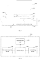
FIG. 1 is a schematic structural view of a fan provided by one embodiment of the present disclosure. -
FIG. 2 is a schematic structural view of a fan provided by one embodiment of the present disclosure. -
FIG. 3 is a schematic structural view of an air conditioning system of provided by one embodiment the present disclosure. -
FIG. 4 is a schematic structural view of a humidifier in an air conditioning system provided by one embodiment of the present disclosure. -
FIG. 5 is a schematic structural view of a fan provided by another embodiment of the present disclosure. -
FIG. 6 is a schematic structural view of an air conditioning system provided by another embodiment of the present disclosure. -
FIG. 7 is a schematic structural view of a humidifier provided by one embodiment of the present invention. - Technical solutions in embodiments of the present disclosure will now be described clearly and completely with reference to accompanying drawings of the embodiments of the present disclosure. Apparently, the described embodiments are only a part of the embodiments of the present disclosure, not all of the embodiments. All other embodiments obtained by a person of ordinary skill in the art based on the embodiments of the present invention without creative efforts shall fall within the protection scope of the present disclosure.
- Referring to
FIG. 1 , afan 100 of one embodiment of the present disclosure includes afan base 110, a transmittingwire coil 120 and afirst control circuit 130. A firstaccommodating space 111 is defined inside thefan base 110. Thefan base 110 is provided with areceiving area 112. Thereceiving area 112 is formed on an upper surface for placing a wireless power receiving device. The transmittingwire coil 120 and thefirst control circuit 130 are arranged in the firstaccommodating space 111. The transmittingwire coil 120 is arranged below thereceiving area 112, and thefirst control circuit 130 is configured to control the transmittingwire coil 120 to transmit wireless power transmission signals to the wireless power receiving device. - The embodiment of the present disclosure can transmit the wireless power transmission signals to the wireless power receiving device placed on the fan base for operation of the wireless power receiving device by setting the transmitting wire coil and a control circuit on the fan base, thus expanding application scope of a wireless power transmission technology and making power supply of the wireless power receiving device more convenient and safe.
- In other embodiments, the transmitting wire coil and the control circuit can also be arranged in a desk, a bedside table or a desk lamp and other devices which are easy to place the wireless power receiving device.
- In the embodiment, a thickness of the receiving
area 112 can be set such that a distance between the transmittingwire coil 120 and a receiving wire coil is less than or equal to 10 mm. - Referring to
FIG. 2 andFIG. 3 together, in the embodiment, the wirelesspower receiving device 200 can be a humidifier, thefan 100 may further include ahumidity sensor 140. Thehumidity sensor 140 may be configured to detect an ambient humidity value. Thefirst control circuit 130 may further adjust power of the wireless power transmission signals according to the ambient humidity value to change the ambient humidity value by controlling the humidifier. - Specifically, the
first control circuit 130 may compare the ambient humidity value with a preset humidity threshold, and supply power to thetransmitting wire coil 120 in response to the ambient humidity value being less than or equal to the preset humidity threshold. The greater absolute difference between the preset humidity threshold and the ambient humidity value, the greater a power supply voltage of thefirst control circuit 130 to thetransmitting wire coil 120. Thus the ambient humidity value can reach the present humidity threshold as soon as possible. For example, if the present humidity threshold is 50%, and thehumidity sensor 140 detects that the ambient humidity value is 45%, thefirst control circuit 130 is configured to supply power to thetransmitting wire coil 120 to make the humidifier start to work. When thehumidity sensor 140 detects that the ambient humidity value exceeds 50%, thefirst control circuit 130 stops supplying power to thetransmitting wire coil 120, and the humidifier stops working. - In the embodiment, the humidifier may include a
humidifier shell 210, areceiving wire coil 220 and asecond control circuit 230. A secondaccommodating space 211 is defined inside thehumidifier shell 210. Thereceiving wire coil 220 and thesecond control circuit 230 are arranged in the secondaccommodating space 211. Thereceiving wire coil 220 is arranged above a bottom of thehumidifier shell 210. Thesecond control circuit 230 is configured to control thereceiving wire coil 220 to receive the wireless power transmission signals from thefan 100. - In the embodiment, the
fan base 110 and thehumidifier shell 210 can be made from acrylonitrile butadiene styrene (ABS) plastic. The ABS plastic can avoid interference and shielding effect on magnetic field generated by thetransmitting wire coil 120 and thereceiving wire coil 220 while ensuring insulation. - The
fan 100 may further include a receivingcircuit 150. The receivingcircuit 150 is configured to receive state parameters of the wirelesspower receiving device 200 from the wirelesspower receiving device 200. Thefirst control circuit 130 may further generate a power adjustment instruction according to state parameters received by the receivingcircuit 150, and adjust the power of the wireless power transmission signals according to the power adjustment instruction. - Specifically, the state parameters received by the receiving
circuit 150 may include a current working voltage, a current working current and target power of the wirelesspower receiving device 200, or the state parameters received by the receivingcircuit 150 may include the current working voltage, the current working current of the wirelesspower receiving device 200 and a target voltage and a target current generated according to the target power. Thefirst control circuit 130 may further generate the target voltage and the target current according to target power received by the receivingcircuit 150, and then generate the power adjustment instruction according to a current working voltage, a current working current, the target voltage and the target current, or generate the power adjustment instruction according to a current working voltage, a current working current, a target voltage and a target current received by the receivingcircuit 150. - For example, referring to
FIG. 4 together, in the embodiment, the humidifier may further include a firststate detection circuit 240 and a transmittingcircuit 250. The firststate detection circuit 240 is configured to detect state parameters of the humidifier. Thesecond control circuit 230 is further configured to generate the power adjustment instruction according to the state parameters. The transmittingcircuit 250 is configured to transmit the state parameters or the power adjustment instruction to thefan 100. - Specifically, a first
state detection circuit 240 of the humidifier detects that a current working voltage of the humidifier is V1 and a current working current of the humidifier is 11. Thesecond control circuit 230 is configured to generate the target voltage VA1 and the target current IA1 according to target power of the humidifier. A transmittingcircuit 250 of the humidifier transmits the current working voltage V1 and the current working current 11 of the humidifier, the target voltage VA1 and the target current IA1 of the humidifier to a receivingcircuit 150 of thefan 100. Thefirst control circuit 130 calculates values of V1-VA1 and I1-IA1 respectively. If the values are positive, the power adjustment instruction is generated to reduce the power of the wireless power transmission signals. If the values are negative, the power adjustment instruction is generated to increase the power of the wireless power transmission signals. If the values are 0, there is no need to generate the power adjustment instruction. - In other embodiments, the receiving
circuit 150 of thefan 100 can also be configured to receive a power adjustment instruction generated by the wirelesspower receiving device 200 according to the state parameters from the wirelesspower receiving device 200. Thefirst control circuit 130 may further directly adjust the power of the wireless power transmission signals according to a power adjustment instruction received by the receivingcircuit 150. - For example, the first
state detection circuit 240 of the humidifier detects that the current working voltage of the humidifier is V1 and the current working current of the humidifier is 11. Thesecond control circuit 230 is configured to generate the target voltage VA1 and the target current IA1 according to the target power of the humidifier, and further calculate the values of V1-VA1 and I1-IA1 to generate the power adjustment instruction. The transmittingcircuit 250 of the humidifier transmits the power adjustment instruction to the receivingcircuit 150 of thefan 100. - In the embodiment, state parameters detected by the first
state detection circuit 240 may also include at least one or a combination of the current working voltage, the current working current and current working temperature of the humidifier. Thesecond control circuit 230 is further configured to compare the at least one or the combination with a corresponding protection threshold, and generate a protection instruction in response to the at least one or the combination being greater than the corresponding protection threshold. The transmittingcircuit 250 of the humidifier transmits the protection instruction to the receivingcircuit 150 of thefan 100, and thefirst control circuit 130 further reduces the power of the wireless power transmission signals or stops the power supply to thetransmitting wire coil 120 according to the protection instruction. - For example, the first
state detection circuit 240 detects that the current working voltage of the humidifier is VI, the current working current is 11, the current working temperature is T1, a preset protection voltage is VH1, a protection current is IH1, and protection temperature is TH1. Thesecond control circuit 230 is configured to generate the protection instruction when any one of V1 > VH1, 11 > IH1, T1 > TH1 is established. - In other embodiments, the state parameters received by the receiving
circuit 150 may also include at least one or a combination of the current working voltage, the current working current and the current working temperature of the wirelesspower receiving device 200. Thefirst control circuit 130 is further configured to compare the at least one or the combination with a corresponding protection threshold and reduce the power of the wireless power transmission signals or stop power supply to thetransmitting wire coil 120 in response to the protection threshold being greater than the corresponding protection threshold. - In the embodiment, the
fan 100 may further include a secondstate detection circuit 160. The secondstate detection circuit 160 can also be configured to detect at least one or a combination of a current working voltage, a current working current and current working temperature of thefan 100. Thefirst control circuit 130 is further configured to compare the at least one or the combination with a corresponding protection threshold, and reduce the power of the wireless power transmission signal or stop power supply to thetransmitting wire coil 120 in response to the at least one or the combination being greater than the corresponding protection threshold. - For example, the second
state detection circuit 160 detects that current working voltage of thefan 100 is V2, the current working current of thefan 100 is 12, the current working temperature of thefan 100 is T2, a preset protection voltage is VH2, a protection current is IH2, protection temperature is TH2. Thefirst control circuit 130 reduces the power of wireless power transmission signals or stop power supply to thetransmitting wire coil 120 in response to any one of V2 > VH2, I2 > IH2, T2 > TH2 being established. - In the embodiment, the thickness of the receiving
area 112 is d1, a bottom thickness of thehumidifier shell 210 is d2, a sum of d1 and d2 is the distance between the transmittingwire coil 120 and thereceiving wire coil 220, and the sum of d1 and d2 is set to be less than or equal to 10 mm to make the distance between the transmittingwire coil 120 and thereceiving wire coil 220 less than or equal to 10 mm, such as 7mm, 9mm or 10mm. - In the embodiment, the upper surface of the
fan base 110 may also be provided with an identification (not shown in the figure). The identification is configured to identify the receivingarea 112 to avoid excessive offset of a position of thereceiving wire coil 220 of the wirelesspower receiving device 200 relative to a position of thetransmitting wire coil 120 of thefan 100. An area of thetransmitting wire coil 120 is set to be greater than or equal to an area of thereceiving wire coil 220. Thus when thereceiving wire coil 220 is offset from thetransmitting wire coil 120, the power and efficiency of the wireless power transmission signals can still be guaranteed. - In the embodiment, the second
state detection circuit 160 detects the current working voltage of thefan 100, and the receivingcircuit 150 receives the current working voltage of the wirelesspower receiving device 200 from the wirelesspower receiving device 200. Thefirst control circuit 130 is further configured to compare the current working voltage of thefan 100 with the current working voltage of the wirelesspower receiving device 200, and generate a prompt signal for repositioning the wirelesspower receiving device 200 in response to difference between the current working voltage of thefan 100 and the current working voltage of the wirelesspower receiving device 200 being greater than a preset difference threshold. Thus in response to offset of the position of thereceiving wire coil 220 of the wirelesspower receiving device 200 relative to the position of thetransmitting wire coil 120 of thefan 100 being excessive, the prompt signal can remind users in time and reduce invalid output of the wireless power transmission signals. - In other embodiments, the wireless
power receiving device 200 can also be an electrical appliance such as a mobile phone, an electric toothbrush, and the like. The wirelesspower receiving device 200 is provided with the receiving wire coil to receive the wireless power transmission signals from thefan 100 to realize the power supply to the wirelesspower receiving device 200. - Referring to
FIG. 5 and FIG. 6 , in another embodiment, the receivingarea 112 of thefan base 110 can also be provided with apositioning clip 113 configured to position the wirelesspower receiving device 200. A bottom of the wirelesspower receiving device 200 can also be provided with agroove 212 corresponding to thepositioning clip 113. Positioning the wirelesspower receiving device 200 through thepositioning clip 113 can more effectively avoid the excessive offset of the position of thereceiving wire coil 220 of the wirelesspower receiving device 200 relative to the position of thetransmitting wire coil 120 of thefan 100. - Referring to
FIG. 7 , the humidifier of the embodiment of the present disclosure includes thehumidifier shell 210, thereceiving wire coil 220 and thecontrol circuit 230. For structures of thehumidifier shell 210, thereceiving wire coil 220 and thecontrol circuit 230, please refer to thehumidifier shell 210, thereceiving wire coil 220 and thesecond control circuit 230 in the fan embodiment, which will not be repeated here. - In other embodiments, the humidifier can also receive the wireless power transmission signals from other wireless power transmission devices, such as a wireless charging stand, and the like.
- The embodiment of the present disclosure can receive the wireless power transmission signals of the wireless power transmission device at a bottom of the humidifier for operation, thus expanding the application scope of the wireless transmission technology and making power supply of the humidifier more convenient and safe.
- Referring to
FIG. 3 , an air conditioning system of one embodiment of the present disclosure includes thefan 100 and the humidifier as the wirelesspower receiving device 200. For structures of thefan 100 and the humidifier, please refer to the fan of the above embodiment, which will not be repeated here. - The embodiment of the present disclosure can realize the wireless power transmission of the fan to the humidifier by setting wire coils and the control circuits respectively in the fan and the humidifier, and can realize linkage between the fan and the humidifier, effectively adjust humidity and temperature of air, thus expanding the application scope of the wireless power transmission technology, and making the power supply of the humidifier more convenient and safe.
- The above description merely depicts some exemplary embodiments of the present disclosure, but is not intended to limit the scope of the present disclosure. Any equivalent structural variations or equivalent process flow variations of the described embodiments and the accompanying drawings, or direct or indirect applications in other relevant technical fields, shall all be covered within the scope of protection of the present disclosure.
Claims (15)
- A fan, comprising:a fan base, wherein an accommodating space is defined inside the fan base, and an upper surface of the fan base is provided with a receiving area configured to place a wireless power receiving device;a transmitting wire coil and a control circuit, arranged in the accommodating space, wherein the transmitting wire coil is arranged below the receiving area, and the control circuit is configured to control the transmitting wire coil to transmit wireless power transmission signals to the wireless power receiving device.
- The fan according to claim 1, wherein an area of the transmitting wire coil is set to be greater than or equal to an area of a receiving wire coil of the wireless power receiving device for receiving the wireless power transmission signals.
- The fan according to claim 1, wherein a thickness of the receiving area is set such that a distance between the transmitting wire coil and the receiving wire coil is less than or equal to 10 mm.
- The fan according to claim 1, wherein the receiving area is provided with a positioning clip for positioning the wireless power receiving device.
- The fan according to claim 1, wherein the wireless power receiving device is a humidifier, the fan further comprises a humidity sensor, the humidity sensor is configured to detect an ambient humidity value, and the control circuit further adjusts power of the wireless power transmission signals according to the ambient humidity value.
- The fan according to claim 5, wherein the control circuit is configured to compare the ambient humidity value with a preset humidity threshold, and supply power to the transmitting wire coil in response to the ambient humidity value being less than or equal to the preset humidity threshold.
- The fan according to claim 1, further comprising:a receiving circuit configured to receive, from the wireless power receiving device, state parameters of the wireless power receiving device or a power adjustment instruction generated by the wireless power receiving device according to the state parameters;wherein the control circuit is further configured to generate the power adjustment instruction according to state parameters received by the receiving circuit, and adjust the power of the wireless power transmission signals according to the power adjustment instruction, or directly adjust the power of the wireless power transmission signals according to a power adjustment instruction received by the receiving circuit.
- The fan according to claim 7, wherein the state parameters received by the receiving circuit comprises a current working voltage, a current working current of the wireless power receiving device and target power of the wireless power receiving device, or the state parameters received by the receiving circuit comprises the current working voltage and the current working current of the wireless power receiving device, and a target voltage and a target current generated according to the target power;
the control circuit is further configured to generate a target voltage and a target current according to target power received by the receiving circuit, and then generate the power adjustment instruction according to a current working voltage, a current working current, the target voltage and the target current, or generate the power adjustment instruction according to a current working voltage, a current working current, a target voltage and a target current received by the receiving circuit. - The fan according to claim 7, wherein the receiving circuit is further configured to receive a protection instruction, and the state parameters received by the receiving circuit comprises at least one or a combination of the current working voltage, the current working current and current working temperature of the wireless power receiving device; and
the control circuit is further configured to reduce the power of the wireless power transmission signals or stop power supply to the transmitting wire coil according to a protection instruction received by the receiving circuit, or compare the at least one or the combination with a corresponding protection threshold, and reduce the power of the wireless power transmission signals or stop the power supply to the transmitting wire coil in response to the at least one or the combination being greater than the corresponding protection threshold. - The fan according to claim 1, wherein the fan further comprises a state detection circuit, the state detection circuit is configured to detect at least one or a combination of a current working voltage, a current working current and current working temperature of the fan, and the control circuit is further configured to compare the at least one or the combination with a corresponding protection threshold, and reduce power of the wireless power transmission signals or stop power supply to the transmitting wire coil in response to the at least one or the combination being greater than the corresponding protection threshold.
- The fan according to claim 1, further comprising:a state detection circuit configured to detect a current working voltage of the fan;a receiving circuit configured to receive a current working voltage of the wireless power receiving device from the wireless power receiving device;the control circuit is further configured to compare the current working voltage of the fan with the current working voltage of the wireless power receiving device, and generate a prompt signal for repositioning the wireless power receiving device in response to difference between the current working voltage of the fan and the current working voltage of the wireless power receiving device being greater than a preset difference threshold.
- A humidifier, comprising:a humidifier shell, wherein an accommodating space is defined inside the humidifier shell;a receiving wire coil and a control circuit arranged in the accommodating space, wherein the receiving wire coil is arranged above a bottom of the humidifier shell, and the control circuit is configured to control the receiving wire coil to receive wireless power transmission signals from a wireless power transmission device.
- The humidifier according to claim 12, wherein the humidifier further comprises a state detection circuit and a transmitting circuit, the state detection circuit is configured to detect state parameters of the humidifier, and the control circuit is further configured to generate a power adjustment instruction according to state parameters, the transmitting circuit is configured to transmit the state parameters or the power adjustment instruction to the wireless power transmission device.
- The humidifier according to claim 13, wherein the state parameters comprise at least one or a combination of a current working voltage, a current working current and current working temperature of the humidifier, and the control circuit is further configured to compare the at least one or the combination with a corresponding protection threshold, and generate a protection instruction in response to the at least one or the combination being greater than the corresponding protection threshold.
- An air conditioning system, comprising the fan according to any one of claims 1 to 11 and the humidifier according to any one of claims 12 to 14 as the wireless power receiving device.
Applications Claiming Priority (2)
| Application Number | Priority Date | Filing Date | Title |
|---|---|---|---|
| CN201811584241.XA CN109631261A (en) | 2018-12-24 | 2018-12-24 | A kind of fan, humidifier and air handling system |
| PCT/CN2019/123813 WO2020134987A1 (en) | 2018-12-24 | 2019-12-06 | Fan, humidifier and air conditioning system |
Publications (3)
| Publication Number | Publication Date |
|---|---|
| EP3875865A1 true EP3875865A1 (en) | 2021-09-08 |
| EP3875865A4 EP3875865A4 (en) | 2022-01-05 |
| EP3875865B1 EP3875865B1 (en) | 2026-04-29 |
Family
ID=66076965
Family Applications (1)
| Application Number | Title | Priority Date | Filing Date |
|---|---|---|---|
| EP19902938.0A Active EP3875865B1 (en) | 2018-12-24 | 2019-12-06 | Fan and air conditioning system |
Country Status (4)
| Country | Link |
|---|---|
| EP (1) | EP3875865B1 (en) |
| CN (1) | CN109631261A (en) |
| AU (1) | AU2019412262B2 (en) |
| WO (1) | WO2020134987A1 (en) |
Families Citing this family (3)
| Publication number | Priority date | Publication date | Assignee | Title |
|---|---|---|---|---|
| CN109631261A (en) * | 2018-12-24 | 2019-04-16 | 广东美的白色家电技术创新中心有限公司 | A kind of fan, humidifier and air handling system |
| CN112902337B (en) * | 2019-12-04 | 2022-06-28 | 佛山市云米电器科技有限公司 | Household equipment control method, system, control equipment and readable storage medium |
| CN112781193B (en) * | 2021-01-29 | 2022-07-19 | 青岛海尔空调器有限总公司 | Method and device for humidifying and humidifying air conditioner |
Family Cites Families (37)
| Publication number | Priority date | Publication date | Assignee | Title |
|---|---|---|---|---|
| JPH08166159A (en) * | 1994-12-13 | 1996-06-25 | Seiki Suyama | Exhaust fan control system |
| CN101123318A (en) * | 2007-08-02 | 2008-02-13 | 深圳市杰特电信控股有限公司 | A wireless charging mobile phone, charging device and its charging method |
| JP5480573B2 (en) * | 2009-09-25 | 2014-04-23 | パナソニック株式会社 | Contactless charging system |
| CN201773332U (en) * | 2009-12-31 | 2011-03-23 | 北京亚都室内环保科技股份有限公司 | Remote-sensing humidity controller |
| CN102323746B (en) * | 2011-05-19 | 2012-11-28 | 福州核心电子科技有限公司 | Fan with clock display function |
| CN202190128U (en) * | 2011-07-04 | 2012-04-11 | 东南大学 | Mobile wireless power charging device of wireless sensor network node |
| KR101976176B1 (en) * | 2012-05-17 | 2019-05-08 | 엘지전자 주식회사 | Mobile terminal |
| CN102705963A (en) * | 2012-05-21 | 2012-10-03 | 台州铭宝电器有限公司 | Humidifier |
| CN102856966A (en) * | 2012-08-28 | 2013-01-02 | 奇瑞汽车股份有限公司 | Control circuit for working state of vehicle-mounted wireless charger and control method thereof |
| CN103812149A (en) * | 2012-11-09 | 2014-05-21 | 海尔集团公司 | Wireless charging device, charging system and charging method |
| CN102997369A (en) * | 2012-12-12 | 2013-03-27 | 北京时代凌宇科技有限公司 | Humidifier control method |
| CN203272188U (en) * | 2013-03-29 | 2013-11-06 | 合肥科盛微电子科技有限公司 | Bladeless fan base with wireless communication function |
| CN203272074U (en) * | 2013-04-08 | 2013-11-06 | 合肥科盛微电子科技有限公司 | Bladeless fan with composite charging mode |
| CN203554079U (en) * | 2013-11-07 | 2014-04-16 | 中国矿业大学 | Wireless power supply air humidifier |
| TWI535369B (en) * | 2014-04-02 | 2016-05-21 | 建準電機工業股份有限公司 | Fan |
| CN204025111U (en) * | 2014-07-31 | 2014-12-17 | 深圳市邦的科技有限公司 | A kind of mini electric fan with wireless charging function |
| CN104215241B (en) * | 2014-09-02 | 2017-07-04 | 常州巴乌克智能科技有限公司 | Inertial Sensor Unit |
| CN204165144U (en) * | 2014-09-28 | 2015-02-18 | 杭州安索科技有限公司 | A kind of air purifier with wireless charging function |
| CN104269908A (en) * | 2014-10-24 | 2015-01-07 | 英华达(上海)科技有限公司 | Wireless charging prompting method and system |
| CN105783170A (en) * | 2014-12-22 | 2016-07-20 | 重庆市逸琨电子科技有限公司 | Self-control humidifier |
| KR101663191B1 (en) * | 2015-01-30 | 2016-10-07 | 한솔테크닉스(주) | Humidification apparatus of radio charge base |
| US10193390B2 (en) * | 2015-03-06 | 2019-01-29 | Mediatek Inc. | Wireless power transmitter configuration for power transmission through a partition |
| CN204858756U (en) * | 2015-08-25 | 2015-12-09 | 厦门新页科技有限公司 | A wireless charging air purifier |
| CN205102319U (en) * | 2015-10-22 | 2016-03-23 | 天津市秀凤通商科技有限公司 | Intelligent humidifier |
| CN205332439U (en) * | 2016-01-28 | 2016-06-22 | 天津商业大学 | Intelligence spraying type humidifier |
| CN205842954U (en) * | 2016-06-28 | 2016-12-28 | 洪流 | Negative ion air-cleaner |
| KR101867084B1 (en) * | 2016-06-30 | 2018-06-12 | 정현종 | Portable air purifiers equipped with a wireless charging module |
| TWM533131U (en) * | 2016-08-25 | 2016-12-01 | Jun-Ru Cai | Remote-controlled electric fan with power socket |
| KR102629988B1 (en) * | 2016-12-29 | 2024-01-26 | 엘지전자 주식회사 | Wireless humidifier set |
| KR102087932B1 (en) * | 2017-01-23 | 2020-03-11 | (주)네오티즌 | Ultrasonic humidifier linked sound source |
| CN106870416A (en) * | 2017-03-11 | 2017-06-20 | 安聪聪 | A kind of electric fan with humidification function |
| CN107222040A (en) * | 2017-06-28 | 2017-09-29 | 温州市鹿城区中津先进科技研究院 | Wireless charging reminding method |
| CN107171403A (en) * | 2017-07-11 | 2017-09-15 | 珠海优特电力科技股份有限公司 | Transmission adaptor |
| CN207381999U (en) * | 2017-08-31 | 2018-05-18 | 杭州宇隆科技有限公司 | A wireless charging base |
| CN108105132A (en) * | 2017-12-27 | 2018-06-01 | 杨玉美 | A kind of portable intelligent adjusts the mini fan of wind speed |
| CN207835162U (en) * | 2018-01-30 | 2018-09-07 | 深圳市隆客色电子技术有限公司 | Portable radiotelephone charger |
| CN109631261A (en) * | 2018-12-24 | 2019-04-16 | 广东美的白色家电技术创新中心有限公司 | A kind of fan, humidifier and air handling system |
-
2018
- 2018-12-24 CN CN201811584241.XA patent/CN109631261A/en active Pending
-
2019
- 2019-12-06 WO PCT/CN2019/123813 patent/WO2020134987A1/en not_active Ceased
- 2019-12-06 AU AU2019412262A patent/AU2019412262B2/en active Active
- 2019-12-06 EP EP19902938.0A patent/EP3875865B1/en active Active
Also Published As
| Publication number | Publication date |
|---|---|
| WO2020134987A1 (en) | 2020-07-02 |
| CN109631261A (en) | 2019-04-16 |
| EP3875865B1 (en) | 2026-04-29 |
| AU2019412262A1 (en) | 2021-06-24 |
| AU2019412262B2 (en) | 2022-06-02 |
| EP3875865A4 (en) | 2022-01-05 |
Similar Documents
| Publication | Publication Date | Title |
|---|---|---|
| EP3875865A1 (en) | Fan, humidifier and air conditioning system | |
| KR102544891B1 (en) | Method and apparatus of adjusting coil location in wireless power transfer system | |
| EP3734795B1 (en) | Apparatus and method for performing power calibration in wireless power transmission system | |
| KR101188808B1 (en) | Wireless charging apparatus for mobile | |
| CN114584633B (en) | Wireless power transmitting device and method and wireless power receiving device and method | |
| CN106451684A (en) | Method and device for intelligently controlling wireless charging and system thereof | |
| WO2018219191A1 (en) | Wirelessly charging lighting apparatus | |
| KR102680015B1 (en) | Wireless charging system and wireless charging method | |
| WO2022078178A1 (en) | Wireless earbud charging case, charging case, and wireless charging system | |
| PH12017000287A1 (en) | Method and indicating system for a vehicle | |
| KR101228105B1 (en) | Wireless charging system and the control method | |
| EP4624818A3 (en) | Thermostat with detachable dial control | |
| WO2021080208A1 (en) | Small home appliance, and method for performing communication in small home appliance | |
| CN207588505U (en) | A wireless charging desk lamp | |
| CN206340733U (en) | A kind of guiding power outlet | |
| KR20170120018A (en) | Remote control device | |
| EP4228117A1 (en) | Wireless earphone charging case, charging case, and wireless charging system | |
| TWI586069B (en) | Wireless charging portable device and control method thereof | |
| CN113937897B (en) | Wireless charging equipment | |
| WO2021075754A1 (en) | Electric kettle and operation method thereof | |
| CN214850649U (en) | Charging blanket for wireless electronic equipment | |
| TW202025598A (en) | Wireless power transmitting apparatus and pot thereof | |
| CN206379747U (en) | A kind of non-contact power charging system | |
| CN209995820U (en) | Heat preservation bowl | |
| CN203673647U (en) | Wireless infrared forwarding device with information feedback function |
Legal Events
| Date | Code | Title | Description |
|---|---|---|---|
| STAA | Information on the status of an ep patent application or granted ep patent |
Free format text: STATUS: THE INTERNATIONAL PUBLICATION HAS BEEN MADE |
|
| PUAI | Public reference made under article 153(3) epc to a published international application that has entered the european phase |
Free format text: ORIGINAL CODE: 0009012 |
|
| STAA | Information on the status of an ep patent application or granted ep patent |
Free format text: STATUS: REQUEST FOR EXAMINATION WAS MADE |
|
| 17P | Request for examination filed |
Effective date: 20210602 |
|
| AK | Designated contracting states |
Kind code of ref document: A1 Designated state(s): AL AT BE BG CH CY CZ DE DK EE ES FI FR GB GR HR HU IE IS IT LI LT LU LV MC MK MT NL NO PL PT RO RS SE SI SK SM TR |
|
| A4 | Supplementary search report drawn up and despatched |
Effective date: 20211206 |
|
| RIC1 | Information provided on ipc code assigned before grant |
Ipc: F24F 110/20 20180101ALI20211130BHEP Ipc: F04D 27/00 20060101ALI20211130BHEP Ipc: F24F 11/56 20180101ALI20211130BHEP Ipc: F24F 11/64 20180101AFI20211130BHEP |
|
| DAV | Request for validation of the european patent (deleted) | ||
| DAX | Request for extension of the european patent (deleted) | ||
| STAA | Information on the status of an ep patent application or granted ep patent |
Free format text: STATUS: EXAMINATION IS IN PROGRESS |
|
| 17Q | First examination report despatched |
Effective date: 20231128 |
|
| GRAP | Despatch of communication of intention to grant a patent |
Free format text: ORIGINAL CODE: EPIDOSNIGR1 |
|
| STAA | Information on the status of an ep patent application or granted ep patent |
Free format text: STATUS: GRANT OF PATENT IS INTENDED |
|
| INTG | Intention to grant announced |
Effective date: 20260206 |
|
| GRAS | Grant fee paid |
Free format text: ORIGINAL CODE: EPIDOSNIGR3 |
|
| GRAA | (expected) grant |
Free format text: ORIGINAL CODE: 0009210 |
|
| STAA | Information on the status of an ep patent application or granted ep patent |
Free format text: STATUS: THE PATENT HAS BEEN GRANTED |
|
| AK | Designated contracting states |
Kind code of ref document: B1 Designated state(s): AL AT BE BG CH CY CZ DE DK EE ES FI FR GB GR HR HU IE IS IT LI LT LU LV MC MK MT NL NO PL PT RO RS SE SI SK SM TR |
|
| REG | Reference to a national code |
Ref country code: CH Ref legal event code: F10 Free format text: ST27 STATUS EVENT CODE: U-0-0-F10-F00 (AS PROVIDED BY THE NATIONAL OFFICE) Effective date: 20260429 |