EP3875816B1 - Calibration method of a pressure-limiting valve - Google Patents
Calibration method of a pressure-limiting valve Download PDFInfo
- Publication number
- EP3875816B1 EP3875816B1 EP21160565.4A EP21160565A EP3875816B1 EP 3875816 B1 EP3875816 B1 EP 3875816B1 EP 21160565 A EP21160565 A EP 21160565A EP 3875816 B1 EP3875816 B1 EP 3875816B1
- Authority
- EP
- European Patent Office
- Prior art keywords
- valve
- pressure
- seat
- inlet
- chamber
- Prior art date
- Legal status (The legal status is an assumption and is not a legal conclusion. Google has not performed a legal analysis and makes no representation as to the accuracy of the status listed.)
- Active
Links
Images



Classifications
-
- F—MECHANICAL ENGINEERING; LIGHTING; HEATING; WEAPONS; BLASTING
- F16—ENGINEERING ELEMENTS AND UNITS; GENERAL MEASURES FOR PRODUCING AND MAINTAINING EFFECTIVE FUNCTIONING OF MACHINES OR INSTALLATIONS; THERMAL INSULATION IN GENERAL
- F16K—VALVES; TAPS; COCKS; ACTUATING-FLOATS; DEVICES FOR VENTING OR AERATING
- F16K17/00—Safety valves; Equalising valves, e.g. pressure relief valves
- F16K17/02—Safety valves; Equalising valves, e.g. pressure relief valves opening on surplus pressure on one side; closing on insufficient pressure on one side
- F16K17/04—Safety valves; Equalising valves, e.g. pressure relief valves opening on surplus pressure on one side; closing on insufficient pressure on one side spring-loaded
- F16K17/0406—Safety valves; Equalising valves, e.g. pressure relief valves opening on surplus pressure on one side; closing on insufficient pressure on one side spring-loaded in the form of balls
-
- F—MECHANICAL ENGINEERING; LIGHTING; HEATING; WEAPONS; BLASTING
- F16—ENGINEERING ELEMENTS AND UNITS; GENERAL MEASURES FOR PRODUCING AND MAINTAINING EFFECTIVE FUNCTIONING OF MACHINES OR INSTALLATIONS; THERMAL INSULATION IN GENERAL
- F16K—VALVES; TAPS; COCKS; ACTUATING-FLOATS; DEVICES FOR VENTING OR AERATING
- F16K17/00—Safety valves; Equalising valves, e.g. pressure relief valves
- F16K17/02—Safety valves; Equalising valves, e.g. pressure relief valves opening on surplus pressure on one side; closing on insufficient pressure on one side
- F16K17/04—Safety valves; Equalising valves, e.g. pressure relief valves opening on surplus pressure on one side; closing on insufficient pressure on one side spring-loaded
- F16K17/06—Safety valves; Equalising valves, e.g. pressure relief valves opening on surplus pressure on one side; closing on insufficient pressure on one side spring-loaded with special arrangements for adjusting the opening pressure
-
- F—MECHANICAL ENGINEERING; LIGHTING; HEATING; WEAPONS; BLASTING
- F16—ENGINEERING ELEMENTS AND UNITS; GENERAL MEASURES FOR PRODUCING AND MAINTAINING EFFECTIVE FUNCTIONING OF MACHINES OR INSTALLATIONS; THERMAL INSULATION IN GENERAL
- F16K—VALVES; TAPS; COCKS; ACTUATING-FLOATS; DEVICES FOR VENTING OR AERATING
- F16K17/00—Safety valves; Equalising valves, e.g. pressure relief valves
- F16K17/40—Safety valves; Equalising valves, e.g. pressure relief valves with a fracturing member, e.g. fracturing diaphragm, glass, fusible joint
- F16K17/406—Safety valves; Equalising valves, e.g. pressure relief valves with a fracturing member, e.g. fracturing diaphragm, glass, fusible joint the fracturing member being a generally elongated member, e.g. rod or wire, which is directly connected to a movable valve member, the breaking or buckling of the elongated member allowing the valve member to move to a closed or open position
-
- F—MECHANICAL ENGINEERING; LIGHTING; HEATING; WEAPONS; BLASTING
- F16—ENGINEERING ELEMENTS AND UNITS; GENERAL MEASURES FOR PRODUCING AND MAINTAINING EFFECTIVE FUNCTIONING OF MACHINES OR INSTALLATIONS; THERMAL INSULATION IN GENERAL
- F16K—VALVES; TAPS; COCKS; ACTUATING-FLOATS; DEVICES FOR VENTING OR AERATING
- F16K37/00—Special means in or on valves or other cut-off apparatus for indicating or recording operation thereof, or for enabling an alarm to be given
- F16K37/0075—For recording or indicating the functioning of a valve in combination with test equipment
- F16K37/0091—For recording or indicating the functioning of a valve in combination with test equipment by measuring fluid parameters
Definitions
- the present invention relates to a calibration method of a pressure-limiting valve.
- FIG 3 illustrates a calibration method according to the prior art of a pressure-limiting valve 1 (hereafter also indicated as valve 1) of known type.
- valve 1 a pressure-limiting valve 1
- FIG. 3 illustrates a calibration method according to the prior art of a pressure-limiting valve 1 (hereafter also indicated as valve 1) of known type.
- valve 1 the main components of the valve 1 will be described in order to illustrate the known calibration method.
- the valve 1 comprises a valve body 2, provided with a central hole 3 which extends along an axis 4.
- the central hole 3 defines, at a first end thereof, an opening 5 and, at a second end, a valve seat 6; furthermore, the valve seat 6 houses a movable element 7, which comprises an elongated portion coaxial with the axis 4 (needle) and is provided, at an enlarged end thereof, facing the opening 5, with a recess, adapted to contain a ball 8 (for example, of steel).
- the valve seat 6 further houses a spring 9, arranged coaxial with the axis 4 and provided with a first end, arranged in contact with a bottom wall of the valve seat 6, and with a second end, arranged in contact with the enlarged portion of the movable element 7.
- the valve 1 further comprises a cylindrical abutment seat 10, which is arranged in the central hole 3 and has a central portion defining a channel 11 coaxial with the axis 4.
- the cylindrical seat 10 is implanted at a preset height inside the central hole 3, so that the spring 9 assumes a preset compression value and pushes the ball 8 against the cylindrical abutment seat 10 closing the channel 11 with a thrust force F equal to a calibration value Ft.
- Such operation is carried out by means of a calibration tool 12, which is provided with a punch 13 which penetrates in the opening 5 and abuts on the cylindrical abutment seat 10 displacing it axially.
- the spring 9 is compressed by effect of a thrust force F s , applied by the cylindrical abutment seat 10 until reaching a height such that the force F corresponds to the desired objective calibration force value F t so that the valve 1 opens.
- the measurement of the opening pressure can be carried out in a direct manner by supplying a fluid under pressure to the valve.
- the measurement of the force is crucial since the dynamic of the valve is strongly affected by the flow rate of fluid flowing through it; furthermore, the flow rate of fluid cannot be determined using a simple fixed orifice, since the flow rate depends on the opening pressure.
- An orifice defined for generating a flow rate to the target opening pressure will generate a much higher flow rate in the first pressure measurements, when the valve has not yet been calibrated.
- US 4 464 931 A also discloses a known method of calibration of a valve.
- the technical problem is thus to calibrate the valve with the direct method, i . e . supplying fluid under pressure and, ensuring a stable process, enabling the valve to open in steady state, so as to ensure high precision, accuracy and replicability in achieving the target opening pressure and so as to preserve the integrity of the valve.
- Figure 2 schematically shows the present calibration method applied to the valve 1 of Figure 1 .
- the method is based on an iterative and adaptive algorithm, wherein it is possible to optimise the number of steps necessary for completing the calibration of the valve 1.
- the pressure-limiting valve 1, schematically illustrated in Figure 1 comprises a valve body 2, provided with a central cylindrical hole 3, extending along an axis 4.
- the central cylindrical hole 3 defines, at a first end thereof, an opening 5 and, at a second end, a valve seat 6; in particular, the valve seat 6 houses a movable element 7, which comprises an elongated portion 7a (needle) which is coaxial with the axis 4 and is provided at an enlarged end 7b thereof transverse to the axis 4 and facing the opening 5, with a recess, adapted to contain a ball 8 (for example, of steel).
- a movable element 7 which comprises an elongated portion 7a (needle) which is coaxial with the axis 4 and is provided at an enlarged end 7b thereof transverse to the axis 4 and facing the opening 5, with a recess, adapted to contain a ball 8 (for example, of steel).
- the valve seat 6 further houses a spring 9, arranged coaxially with the axis 4 and provided with a first end, arranged in contact with a bottom wall of the valve seat 6, and with a second end, arranged in contact with the enlarged portion 7b of the movable element 7.
- the valve 1 further comprises a cylindrical abutment seat 10, which is arranged in the central hole 3.
- the cylindrical abutment seat 10 has a central portion defining a channel 11 coaxial with the axis 4 and communicating at a first end thereof with an inlet 22 of the valve 1.
- the ball 8 In use, in the closing position ( Figure 1 ) of the valve, the ball 8 abuts on the seat 10 and closes a second end of the channel 11.
- the spring 9 exerts an elastic force which maintains, in the aforementioned closing condition of the valve, the ball 8 pressed against the cylindrical seat 10 thus closing the second end of the channel 11.
- the ball 8 separates the channel 11 from a chamber 20 housing the spring 9, the movable element 7 and the ball 8.
- the chamber 20 communicates with an outlet 23 of the valve and the channel 11, as illustrated above, communicates with an inlet 22 of the valve.
- the outlet 23 of the valve is connected with a narrowing device 40 (of known type) which produces a resistance to the discharge of the fluid which outflows from the outlet 23. Furthermore, a sensor 24 is used which measures the pressure in the chamber 20.
- a calibration tool 25 of servo-controlled type is used, i.e. provided with a pusher element 30, movable along the axis 4 under the thrust of motor means (not represented of known type), which are controlled by an electronic control unit 35 operating according to the instructions of Figure 2 and communicating with the sensor 24.
- the calibration tool 25 is arranged above the valve 1 with the pusher element 30 motionless; the cylindrical abutment seat 10 is housed in the valve seat 6 and is spaced with respect to the ball 8.
- the enlarged portion of the movable element 7 is placed on the spring 9, which is in a rest position.
- the cylindrical abutment seat 10 can be previously pre-planted at a height such to load the spring 9 at an intermediate level and lock the ball 8 between the cylindrical abutment seat 10 and the movable element 7.
- a calibration cycle is carried out, wherein an initial block 20 is provided which performs the displacement of the pusher element 30 with respect to the initial position; in particular, the pusher element 30 moves axially downwards, fed towards the bottom of the valve seat 6 of a pre-established distance (block 30) in order to reach a pre-planting height.
- the pusher element 30 abuts on the cylindrical abutment seat 10 (block 30) and moves it for an established distance until the abutment seat 10 abuts on the ball 8 which is arranged in a valve closing position closing the second end of the channel 11.
- the pusher element 30 is a T-shaped element provided with a channel for the supply of fluid under pressure to the inlet 22 of the valve. A gas or a liquid can be supplied.
- the pusher element 30 thus has the function of moving the seat 10 and of supplying fluid under pressure to the inlet 22 of the valve.
- the motion of the pusher element 30 terminates.
- the cylindrical abutment seat 10 has sufficient interference with respect to the hole 5 so as to ensure that, eliminating the thrust exerted by the T-shaped element, it remains locked in position.
- the force applied by the pusher element 30 is above a pre-established threshold (block "Verification minimum contact force", block 35).
- block 37 an error
- the supply of the fluid under pressure is activated (block 50) with a preset opening value of a valve V6 ( Figure 1 ) which supplies fluid under pressure to the inlet 22 of the valve 1 in order to obtain the detachment of the ball 8 from the seat 10 with respect to the closing position, the displacement of the movable element 7 against the action of the spring 9 and thus the opening of the valve 1.
- a valve V6 Figure 1
- the pressure of the fluid has a ramp increase (block 70).
- the ball 8 thus starts moving and the fluid under pressure is supplied in the chamber 20.
- a first step of adjustment is activated.
- a control cycle is performed of the back pressure detected by the transducer 24 acting on the opening degree of the valve V6 in order to maintain the pressure in the chamber equal to an objective value P OUT1 (for example 1 bar) .
- the supply pressure P measured of the valve is acquired (block 100), such pressure is compared with a valve setting target pressure P target calculating the pressure difference ⁇ P (block 110) and subsequently the displacement ⁇ X to be applied to the seat 10 is calculated in order to reduce the pressure difference ⁇ P (block 120) to a minimum value.
- the first adjustment step terminates and the displacement of the pusher element 30 is performed so as to physically perform the movement ⁇ X of the seat 10 (block 140) .
- a first open loop calibration phase thus terminates.
- a control cycle is again performed (blocks 220 and 230) with retroaction of the valve V6 in order to maintain the pressure in the chamber 20 equal to the objective value P OUT1 (for example 1 bar). A further step of adjustment is thus started.
- the calibration phase continues (block 280) with the continuous feed at low speed of the pusher until the condition of the block 250 is satisfied.
- the advantages of the present invention are those implied in the direct calibration, i.e. to have the possibility to calibrate in process the valve progressively displacing the abutment seat 10 which causes the loading of the reaction spring 9 and directly reading the opening pressure of the valve, i.e. of the size that characterises the valve.
- the capability of this method to produce and maintain a condition of stable balance in conditions of open valve, allows measuring the opening pressure in steady state.
- Another advantage is that of eliminating the violent hits that are generated between the ball and the abutment seat at the moment of the opening of the valve, since it is possible to prevent the instability of the ball typical of this type of valves thanks to the pressure present in the chamber 20.
- the above-described method allows calibrating in a direct manner (controlling the opening pressure and not the force of the spring) the valve being opened.
- the method of the present invention is further applicable also in the alternative configuration of Figure 4 wherein the channel 11 is made in the valve body 2 with the ball 8 arranged in abutment on an end portion of the channel 11, the abutment seat 10 is devoid of the channel 11 and is arranged on the opposite side of the movable element 7 with respect to what represented in Figure 1 , i.e. in abutment on a terminal portion of the spring 9.
- the inlet of the channel 11 also embodies the inlet of the valve.
- the pusher element 30 presses on the abutment seat 10 planting it inside the valve seat 6 and compresses the spring on an opposite side with respect to what illustrated in Figure 1 .
- the outlet of the chamber 20 is embodied by a channel 50 which radially extends from the chamber 20 and which communicates with the narrowing 40.
Landscapes
- Engineering & Computer Science (AREA)
- General Engineering & Computer Science (AREA)
- Mechanical Engineering (AREA)
- Control Of Fluid Pressure (AREA)
- Safety Valves (AREA)
- Measuring Fluid Pressure (AREA)
Description
- This patent application claims priority from
Italian patent application no. 102020000004444 filed on 03/03/2020 - The present invention relates to a calibration method of a pressure-limiting valve.
-
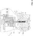
Figure 3 illustrates a calibration method according to the prior art of a pressure-limiting valve 1 (hereafter also indicated as valve 1) of known type. In particular, the main components of thevalve 1 will be described in order to illustrate the known calibration method. - Specifically, the
valve 1 comprises avalve body 2, provided with a central hole 3 which extends along anaxis 4. The central hole 3 defines, at a first end thereof, anopening 5 and, at a second end, avalve seat 6; furthermore, thevalve seat 6 houses amovable element 7, which comprises an elongated portion coaxial with the axis 4 (needle) and is provided, at an enlarged end thereof, facing theopening 5, with a recess, adapted to contain a ball 8 (for example, of steel). Thevalve seat 6 further houses aspring 9, arranged coaxial with theaxis 4 and provided with a first end, arranged in contact with a bottom wall of thevalve seat 6, and with a second end, arranged in contact with the enlarged portion of themovable element 7. - The
valve 1 further comprises acylindrical abutment seat 10, which is arranged in the central hole 3 and has a central portion defining achannel 11 coaxial with theaxis 4. - In particular, according to the known methods, the
cylindrical seat 10 is implanted at a preset height inside the central hole 3, so that thespring 9 assumes a preset compression value and pushes theball 8 against thecylindrical abutment seat 10 closing thechannel 11 with a thrust force F equal to a calibration value Ft. - Such operation is carried out by means of a
calibration tool 12, which is provided with apunch 13 which penetrates in theopening 5 and abuts on thecylindrical abutment seat 10 displacing it axially. - In this way, the
spring 9 is compressed by effect of a thrust force Fs, applied by thecylindrical abutment seat 10 until reaching a height such that the force F corresponds to the desired objective calibration force value Ft so that thevalve 1 opens. - In order to control the calibration force value Ft, this has to be measured in a direct manner; usually, the measurement takes place by using a
tip 14a, mounted coaxially in thepunch 13, which presses on theball 8. - However, in known control methods, not all the boundary conditions are considered, i.e. the variables interposed between the calibration force Ft of the spring and the actual opening pressure, such as for example the tolerance on the seat angle of the sealing, surface finishes of the sealing surfaces. This variability does not allow achieving a sufficient tolerance on the actual opening pressure, since a percentage of the calibration force Ft is reserved to the uncertainty on the boundary conditions.
- Alternatively, the measurement of the opening pressure can be carried out in a direct manner by supplying a fluid under pressure to the valve.
- Also in such case, the measurement of the force is crucial since the dynamic of the valve is strongly affected by the flow rate of fluid flowing through it; furthermore, the flow rate of fluid cannot be determined using a simple fixed orifice, since the flow rate depends on the opening pressure. An orifice defined for generating a flow rate to the target opening pressure will generate a much higher flow rate in the first pressure measurements, when the valve has not yet been calibrated.
- Flow rate values above a certain limit value cause an uncontrolled dynamic on the valve which makes the static and precise measurement of the opening pressure impossible and which has stressful consequences on the components which compose it. In fact, uncontrolled openings and closings occur and the internal ball starts bouncing and hitting the seat, undergoing damage.
-
US 4 464 931 A also discloses a known method of calibration of a valve. - To summarise, at the state of the art there are no reliable methods for carrying out the calibration of the valve in stable conditions.
- The technical problem is thus to calibrate the valve with the direct method, i.e. supplying fluid under pressure and, ensuring a stable process, enabling the valve to open in steady state, so as to ensure high precision, accuracy and replicability in achieving the target opening pressure and so as to preserve the integrity of the valve.
- According to the present invention, a calibration method of a valve is provided, as claimed in the attached claims.
- In order to better understand the present invention, a preferred embodiment thereof is now described, by way of mere non-limiting example, with reference to the accompanying drawings, wherein:
-
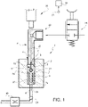
Figure 1 shows a cross-section of a pressure-limiting valve subjected to the method according to the present invention; -
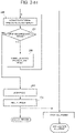
Figure 2 shows a flow chart of the present calibration method; -
Figure 3 illustrates the prior art; and -
Figure 4 illustrates a variant to the method according to the present invention. -
Figure 2 schematically shows the present calibration method applied to thevalve 1 ofFigure 1 . In particular, the method is based on an iterative and adaptive algorithm, wherein it is possible to optimise the number of steps necessary for completing the calibration of thevalve 1. - Specifically, the pressure-limiting
valve 1, schematically illustrated inFigure 1 , comprises avalve body 2, provided with a central cylindrical hole 3, extending along anaxis 4. The central cylindrical hole 3 defines, at a first end thereof, anopening 5 and, at a second end, avalve seat 6; in particular, thevalve seat 6 houses amovable element 7, which comprises anelongated portion 7a (needle) which is coaxial with theaxis 4 and is provided at an enlargedend 7b thereof transverse to theaxis 4 and facing theopening 5, with a recess, adapted to contain a ball 8 (for example, of steel). - The
valve seat 6 further houses aspring 9, arranged coaxially with theaxis 4 and provided with a first end, arranged in contact with a bottom wall of thevalve seat 6, and with a second end, arranged in contact with the enlargedportion 7b of themovable element 7. - The
valve 1 further comprises acylindrical abutment seat 10, which is arranged in the central hole 3. Thecylindrical abutment seat 10 has a central portion defining achannel 11 coaxial with theaxis 4 and communicating at a first end thereof with aninlet 22 of thevalve 1. - In use, in the closing position (
Figure 1 ) of the valve, theball 8 abuts on theseat 10 and closes a second end of thechannel 11. Thespring 9 exerts an elastic force which maintains, in the aforementioned closing condition of the valve, theball 8 pressed against thecylindrical seat 10 thus closing the second end of thechannel 11. The force exerted by thespring 9 depends on the position of thecylindrical abutment seat 10 along theaxis 4 inside the hole 3. With the decrease in the distance between theseat 10 and the bottom wall of thevalve seat 6, the spring is more compressed and the force increases according to the known relation F = k*x. - When the pressure of the fluid supplied from the
inlet 22 of the valve to thechannel 11 exceeds a threshold value, a force is applied to theball 8, said force exceeding that exerted by thespring 9 which is compressed; in this manner, theball 8 is displaced and moves away from thevalve seat 10 and creating an annular space (not represented inFigure 1 ) for the passage of the fluid under pressure which flows through thevalve 1. - The
ball 8 separates thechannel 11 from achamber 20 housing thespring 9, themovable element 7 and theball 8. Thechamber 20 communicates with anoutlet 23 of the valve and thechannel 11, as illustrated above, communicates with aninlet 22 of the valve. - In order to carry out the calibration operations, according to the present invention the
outlet 23 of the valve is connected with a narrowing device 40 (of known type) which produces a resistance to the discharge of the fluid which outflows from theoutlet 23. Furthermore, asensor 24 is used which measures the pressure in thechamber 20. - A
calibration tool 25 of servo-controlled type is used, i.e. provided with apusher element 30, movable along theaxis 4 under the thrust of motor means (not represented of known type), which are controlled by anelectronic control unit 35 operating according to the instructions ofFigure 2 and communicating with thesensor 24. - At the beginning of the calibration process (
Figure 1 illustrates an initial situation of the present valve 1), thecalibration tool 25 is arranged above thevalve 1 with thepusher element 30 motionless; thecylindrical abutment seat 10 is housed in thevalve seat 6 and is spaced with respect to theball 8. The enlarged portion of themovable element 7 is placed on thespring 9, which is in a rest position. Alternatively, thecylindrical abutment seat 10 can be previously pre-planted at a height such to load thespring 9 at an intermediate level and lock theball 8 between thecylindrical abutment seat 10 and themovable element 7. - With reference to
Figure 2 , which illustrates the operations carried out under the control of the electronic unit 15, operating according to the present method, a calibration cycle is carried out, wherein aninitial block 20 is provided which performs the displacement of thepusher element 30 with respect to the initial position; in particular, thepusher element 30 moves axially downwards, fed towards the bottom of thevalve seat 6 of a pre-established distance (block 30) in order to reach a pre-planting height. Thepusher element 30 abuts on the cylindrical abutment seat 10 (block 30) and moves it for an established distance until theabutment seat 10 abuts on theball 8 which is arranged in a valve closing position closing the second end of thechannel 11. InFigure 1 , thepusher element 30 is a T-shaped element provided with a channel for the supply of fluid under pressure to theinlet 22 of the valve. A gas or a liquid can be supplied. Thepusher element 30 thus has the function of moving theseat 10 and of supplying fluid under pressure to theinlet 22 of the valve. The motion of thepusher element 30 terminates. In this position it is necessary to verify that thecylindrical abutment seat 10 has sufficient interference with respect to thehole 5 so as to ensure that, eliminating the thrust exerted by the T-shaped element, it remains locked in position. For this purpose, it is verified that the force applied by thepusher element 30 is above a pre-established threshold (block "Verification minimum contact force", block 35). When the control of theblock 35 produces a negative outcome, an error (block 37) is signalled and the procedure terminates. - Subsequent to the operations described in the
blocks Figure 1 ) which supplies fluid under pressure to theinlet 22 of thevalve 1 in order to obtain the detachment of theball 8 from theseat 10 with respect to the closing position, the displacement of themovable element 7 against the action of thespring 9 and thus the opening of thevalve 1. - Typically, the pressure of the fluid has a ramp increase (block 70).
- The
ball 8 thus starts moving and the fluid under pressure is supplied in thechamber 20. As soon as the forming of a back pressure in thechamber 20 is detected (block 80) caused by the fluid supplied at the inlet to the valve being calibrated (the back pressure is obtained narrowing theoutlet 23 of the valve by means of the narrowing 40 thus limiting the outflow of the fluid) a first step of adjustment is activated. - In the first adjustment step (blocks 90 and 95) a control cycle is performed of the back pressure detected by the
transducer 24 acting on the opening degree of the valve V6 in order to maintain the pressure in the chamber equal to an objective value POUT1 (for example 1 bar) . - During the adjustment step, the supply pressure Pmeasured of the valve is acquired (block 100), such pressure is compared with a valve setting target pressure Ptarget calculating the pressure difference ΔP (block 110) and subsequently the displacement ΔX to be applied to the
seat 10 is calculated in order to reduce the pressure difference ΔP (block 120) to a minimum value. With this calculation, the first adjustment step (block 130) terminates and the displacement of thepusher element 30 is performed so as to physically perform the movement ΔX of the seat 10 (block 140) . - A first open loop calibration phase thus terminates.
- Subsequently, (second calibration phase in a closed loop) fluid under pressure is again supplied to the inlet of the valve (block 200 opening valve V6) until (block 210) in the chamber 20 a pressure is present caused by the fluid supplied at the inlet to the valve being calibrated and not completely discharged by the
chamber 20 thanks to the narrowingdevice 40. - Following a positive verification in the
block 210, a control cycle is again performed (blocks 220 and 230) with retroaction of the valve V6 in order to maintain the pressure in thechamber 20 equal to the objective value POUT1 (for example 1 bar). A further step of adjustment is thus started. - In such further adjustment step:
- the supply pressure Pmeasured of the valve is acquired (block 240),
- the
pusher 30 moves in continuous mode displacing theabutment seat 10; - the pressure Pmeasured is compared (block 250) with the valve setting target pressure Ptarget and when the pressure measured is equal to or greater than the target, the calibration phase ends (the
block 260 controls the stopping of thepusher 30 and theblock 270 controls the arrangement of thepusher 30 in a rest position). - When, instead, the pressure measured Pmeasured is below the target, the calibration phase continues (block 280) with the continuous feed at low speed of the pusher until the condition of the
block 250 is satisfied. - The advantages of the present invention are those implied in the direct calibration, i.e. to have the possibility to calibrate in process the valve progressively displacing the
abutment seat 10 which causes the loading of thereaction spring 9 and directly reading the opening pressure of the valve, i.e. of the size that characterises the valve. The capability of this method to produce and maintain a condition of stable balance in conditions of open valve, allows measuring the opening pressure in steady state. - In this manner, it is possible to calibrate the valve "in continuous" and not by subsequent approximations.
- Another advantage is that of eliminating the violent hits that are generated between the ball and the abutment seat at the moment of the opening of the valve, since it is possible to prevent the instability of the ball typical of this type of valves thanks to the pressure present in the
chamber 20. - The above-described method allows calibrating in a direct manner (controlling the opening pressure and not the force of the spring) the valve being opened.
- The method of the present invention is further applicable also in the alternative configuration of
Figure 4 wherein thechannel 11 is made in thevalve body 2 with theball 8 arranged in abutment on an end portion of thechannel 11, theabutment seat 10 is devoid of thechannel 11 and is arranged on the opposite side of themovable element 7 with respect to what represented inFigure 1 , i.e. in abutment on a terminal portion of thespring 9. - The inlet of the
channel 11 also embodies the inlet of the valve. - In this case, the
pusher element 30 presses on theabutment seat 10 planting it inside thevalve seat 6 and compresses the spring on an opposite side with respect to what illustrated inFigure 1 . - The outlet of the
chamber 20 is embodied by achannel 50 which radially extends from thechamber 20 and which communicates with the narrowing 40. - This type of valve configuration cannot be calibrated with the indirect method of the calibration of the spring pre-load force as this is not accessible.
Claims (8)
- A calibration method of a valve (1), wherein a valve seat (6) houses a movable element (7) which extends along an axis (4), a spring (9) associated with the movable element (7) and a ball (8) carried by the movable element (7) and arranged, in use, in a closing position, in abutment against an abutment seat (10) housed in the valve seat (6) and provided with a channel (11) having a first end configured to be closed by the ball and a second end communicating with an inlet (22) of the valve;the ball (8) separates the channel from a chamber (20) which houses the spring (9), the movable element (7) and the ball and communicates with an outlet (23) of the valve; said method using a calibration tool (25) , provided with a pusher element (30) movable, in use, along said axis (4),the method comprising a calibration phase wherein the following steps are carried out:- axially moving the pusher element (30) so that the pusher element (30) abuts on the abutment seat (10) and displaces it with respect to the valve seat (6) and subsequently stopping the motion of the pusher element (30);- supplying fluid under pressure to the inlet (22) of the valve being calibrated;- creating a narrowing (40) at the outlet (23) of the valve and measuring the pressure inside the chamber (20) detecting a pressure caused by the fluid supplied at the inlet to the valve being calibrated;- carrying out an adjustment step for the flow of the fluid entering the valve wherein the pressure inside said chamber (20) is controlled so that it is close to a set fixed value (Pout);- acquiring (100) the supply pressure (Pmis) of the valve during the adjustment step;- comparing the pressure (Pmis) with a valve setting target pressure (Ptarget) calculating (110) the pressure difference ΔP; andcalculating (120) the displacement (ΔX) to be applied to the seat (10) in order to reduce the pressure difference (ΔP) to a minimum value;- controlling the displacement of the pusher element (30) to physically perform (140) the displacement (ΔX) of the seat (10) terminating the adjustment step (130).
- The method according to claim 1, wherein the step of supplying fluid under pressure to the inlet (22) of the valve being calibrated comprises the step of opening a fluid supply valve (V6) communicating with said inlet (22) so that said fluid supply valve (V6) has a preset opening value;
said pressure adjustment step inside said chamber comprises the step of acting on the opening degree of the fluid supply valve (V6) in order to maintain the pressure in the chamber equal to the set fixed value. - The method according to claim 1 or 2, wherein, after said open loop calibration phase, a further calibration phase is carried out in closed loop.
- - The method according to claim 3, wherein in the further calibration phase in a closed loop, fluid under pressure is again supplied to the inlet of the valve (200) until it is detected that the pressure present in the chamber (20) reaches the set fixed value;
said further adjustment step comprising:acquiring (240) the supply pressure (Pmeasured) of the valve ;controlling in continuous mode the movement of the pusher (30) to modify the position of the abutment seat (10) relative to the valve seat (6);comparing (250) the pressure (Pmeasured)with the valve setting target pressure (Ptarget) and terminating the calibration of the valve when the pressure measured is equal to or greater than the target;continuing the calibration phase when the pressure measured (Pmeasured) is below the target actuating the continuous feed at low speed of the pusher until said comparison produces a positive outcome. - A calibration method of a valve (1), wherein a valve seat (6) houses a movable element (7) which extends along an axis (4), a spring (9) associated with the movable element (7) and a ball (8) carried by the movable element (7) and arranged, in use, in a closing position, in abutment on a first end of a channel having a second end communicating with an inlet (22) of the valve;the ball (8) separates the channel from a chamber (20) which houses the spring (9), the movable element (7) and the ball and communicates with an outlet (23) of the valve;said method using a calibration tool (25), provided with a pusher element (30) movable, in use, along said axis (4),the method comprising a calibration phase wherein the following steps are carried out:- axially moving the pusher element (30) so that the pusher element (30) abuts on an abutment seat (10) housed in the valve seat (6) and displaces it with respect to the valve seat (6) compressing the spring (9) and subsequently stopping the motion of the pusher element (30);- supplying fluid under pressure to the inlet (22) of the valve being calibrated;- creating a narrowing (40) at the outlet (23) of the valve and measuring the pressure inside the chamber (20) detecting a pressure caused by the fluid supplied at the inlet to the valve being calibrated;- carrying out an adjustment step for the flow of the fluid entering the valve wherein the pressure inside said chamber (20) is controlled so that it is close to a set fixed value (Pout);- acquiring (100) the supply pressure (Pmis) of the valve during the adjustment step;- comparing the pressure (Pmis) with a valve setting target pressure (Ptarget) calculating (110) the pressure difference (ΔP); andcalculating (120) the displacement (ΔX) to be applied to the seat (10) in order to reduce the pressure difference (ΔP) to a minimum value;- controlling the displacement of the pusher element (30) to physically perform (140) the displacement (ΔX) of the seat (10) terminating the adjustment step (130).
- The method according to claim 5, wherein the step of supplying fluid under pressure to the inlet (22) of the valve being calibrated comprises the step of opening a fluid supply valve (V6) communicating with said inlet (22) so that said fluid supply valve (V6) has a preset opening value;
said pressure adjustment step inside said chamber comprises the step of acting on the opening degree of the fluid supply valve (V6) in order to maintain the pressure in the chamber equal to the set fixed value. - The method according to claim 5 or 6, wherein after said open loop calibration phase, a further calibration phase is carried out in closed loop.
- - The method according to claim 7, wherein in the further calibration phase in a closed loop, fluid under pressure is again supplied to the inlet of the valve (200) until it is detected that the pressure present in the chamber (20) reaches the set fixed value;
said further adjustment step comprising:acquiring the supply pressure (Pmeasured) of the valve (240) ;controlling in continuous mode the movement of the pusher (30) to modify the position of the abutment seat (10) relative to the valve seat (6);comparing (250) the pressure (Pmeasured) with the valve setting target pressure (Ptarget) and terminating the calibration of the valve when the pressure measured is equal to or greater than the target;- continuing the calibration phase when the pressure measured (Pmeasured) is below the target actuating the continuous feed at low speed of the pusher until said comparison produces a positive outcome.
Applications Claiming Priority (1)
| Application Number | Priority Date | Filing Date | Title |
|---|---|---|---|
| IT102020000004444A IT202000004444A1 (en) | 2020-03-03 | 2020-03-03 | CALIBRATION METHOD OF A PRESSURE RELIEF VALVE |
Publications (2)
| Publication Number | Publication Date |
|---|---|
| EP3875816A1 EP3875816A1 (en) | 2021-09-08 |
| EP3875816B1 true EP3875816B1 (en) | 2022-09-14 |
Family
ID=70614465
Family Applications (1)
| Application Number | Title | Priority Date | Filing Date |
|---|---|---|---|
| EP21160565.4A Active EP3875816B1 (en) | 2020-03-03 | 2021-03-03 | Calibration method of a pressure-limiting valve |
Country Status (4)
| Country | Link |
|---|---|
| EP (1) | EP3875816B1 (en) |
| IT (1) | IT202000004444A1 (en) |
| MX (1) | MX2022010992A (en) |
| WO (1) | WO2021176371A1 (en) |
Citations (1)
| Publication number | Priority date | Publication date | Assignee | Title |
|---|---|---|---|---|
| EP3480565B1 (en) * | 2017-11-02 | 2020-09-09 | MASMEC S.p.A. | Method of calibration for a valve |
Family Cites Families (3)
| Publication number | Priority date | Publication date | Assignee | Title |
|---|---|---|---|---|
| US3042075A (en) * | 1954-11-01 | 1962-07-03 | Vickers Inc | Pressure responsive valve |
| US3554223A (en) * | 1969-05-01 | 1971-01-12 | Gen Motors Corp | Pressure control valve assembly and method of calibration |
| FR2504266A1 (en) * | 1981-04-15 | 1982-10-22 | Sfr Sa Robinetterie | INSTALLATION AND METHOD FOR VERIFYING THE OPERATION OF A FLOW CONTROL AND / OR PRESSURE CONTROLLER UNDER A GIVEN AND CONSTANT FLOW |
-
2020
- 2020-03-03 IT IT102020000004444A patent/IT202000004444A1/en unknown
-
2021
- 2021-03-03 MX MX2022010992A patent/MX2022010992A/en unknown
- 2021-03-03 EP EP21160565.4A patent/EP3875816B1/en active Active
- 2021-03-03 WO PCT/IB2021/051774 patent/WO2021176371A1/en not_active Ceased
Patent Citations (1)
| Publication number | Priority date | Publication date | Assignee | Title |
|---|---|---|---|---|
| EP3480565B1 (en) * | 2017-11-02 | 2020-09-09 | MASMEC S.p.A. | Method of calibration for a valve |
Also Published As
| Publication number | Publication date |
|---|---|
| WO2021176371A1 (en) | 2021-09-10 |
| MX2022010992A (en) | 2023-02-09 |
| IT202000004444A1 (en) | 2021-09-03 |
| EP3875816A1 (en) | 2021-09-08 |
Similar Documents
| Publication | Publication Date | Title |
|---|---|---|
| JP4321342B2 (en) | Common rail fuel injection system | |
| US10151267B2 (en) | Method and device for operating a pressure reservoir, in particular for common rail injection systems in automobile engineering | |
| US8033801B2 (en) | Liquid chemical supply system and liquid chemical supply control device | |
| US20220043466A1 (en) | Flow rate control apparatus, flow rate control method, and program recording medium recording flow rate control program | |
| US9273627B2 (en) | Injection device | |
| CA2556059A1 (en) | Method and device for filling a container with a predetermined quantity of fluid, filling machine | |
| JP7532384B2 (en) | Systems and methods for controlling a dispenser - Patents.com | |
| US20180090353A1 (en) | Method of achieving improved transient response in apparatus for controlling flow and system for accomplishing same | |
| KR101835244B1 (en) | Method for operating a piezo servo injector | |
| TWI709013B (en) | Flow control device and flow control method | |
| JP6824751B2 (en) | Fuel injection amount control device | |
| EP3875816A1 (en) | Calibration method of a pressure-limiting valve | |
| KR20190134787A (en) | Fluid control system and flow measurement method | |
| US9797332B2 (en) | Fuel injection control device and fuel injection control method for internal combustion engine | |
| US11002200B2 (en) | Evaporated fuel processing device | |
| JP7429464B2 (en) | Fluid control device, fluid supply system and fluid supply method | |
| US7000450B2 (en) | Method, computer program and device for measuring the injection quantity of injection nozzles, especially for motor vehicles | |
| KR20190068608A (en) | A method for achieving an increase in both accuracy in a pressure-controlled metering system | |
| JP3590300B2 (en) | Method and apparatus for discharging liquid at high speed and precision | |
| US20240180357A1 (en) | Espresso Extraction Device And Method | |
| JP2018045432A (en) | Vacuum pressure control system and controller for vacuum pressure control | |
| TWI912400B (en) | Pressure control using an external trigger | |
| JP4683788B2 (en) | Hydraulic actuator controller | |
| CN112763178B (en) | Hypersonic wind tunnel regulating valve opening degree presetting method capable of automatically stopping in advance | |
| JP7047293B2 (en) | Relief valve opening judgment device |
Legal Events
| Date | Code | Title | Description |
|---|---|---|---|
| PUAI | Public reference made under article 153(3) epc to a published international application that has entered the european phase |
Free format text: ORIGINAL CODE: 0009012 |
|
| STAA | Information on the status of an ep patent application or granted ep patent |
Free format text: STATUS: THE APPLICATION HAS BEEN PUBLISHED |
|
| AK | Designated contracting states |
Kind code of ref document: A1 Designated state(s): AL AT BE BG CH CY CZ DE DK EE ES FI FR GB GR HR HU IE IS IT LI LT LU LV MC MK MT NL NO PL PT RO RS SE SI SK SM TR |
|
| STAA | Information on the status of an ep patent application or granted ep patent |
Free format text: STATUS: REQUEST FOR EXAMINATION WAS MADE |
|
| GRAP | Despatch of communication of intention to grant a patent |
Free format text: ORIGINAL CODE: EPIDOSNIGR1 |
|
| STAA | Information on the status of an ep patent application or granted ep patent |
Free format text: STATUS: GRANT OF PATENT IS INTENDED |
|
| 17P | Request for examination filed |
Effective date: 20220303 |
|
| RBV | Designated contracting states (corrected) |
Designated state(s): AL AT BE BG CH CY CZ DE DK EE ES FI FR GB GR HR HU IE IS IT LI LT LU LV MC MK MT NL NO PL PT RO RS SE SI SK SM TR |
|
| INTG | Intention to grant announced |
Effective date: 20220405 |
|
| GRAS | Grant fee paid |
Free format text: ORIGINAL CODE: EPIDOSNIGR3 |
|
| GRAA | (expected) grant |
Free format text: ORIGINAL CODE: 0009210 |
|
| STAA | Information on the status of an ep patent application or granted ep patent |
Free format text: STATUS: THE PATENT HAS BEEN GRANTED |
|
| AK | Designated contracting states |
Kind code of ref document: B1 Designated state(s): AL AT BE BG CH CY CZ DE DK EE ES FI FR GB GR HR HU IE IS IT LI LT LU LV MC MK MT NL NO PL PT RO RS SE SI SK SM TR |
|
| REG | Reference to a national code |
Ref country code: GB Ref legal event code: FG4D |
|
| REG | Reference to a national code |
Ref country code: CH Ref legal event code: EP |
|
| REG | Reference to a national code |
Ref country code: DE Ref legal event code: R096 Ref document number: 602021000416 Country of ref document: DE |
|
| REG | Reference to a national code |
Ref country code: IE Ref legal event code: FG4D |
|
| REG | Reference to a national code |
Ref country code: AT Ref legal event code: REF Ref document number: 1518880 Country of ref document: AT Kind code of ref document: T Effective date: 20221015 |
|
| REG | Reference to a national code |
Ref country code: RO Ref legal event code: EPE |
|
| REG | Reference to a national code |
Ref country code: LT Ref legal event code: MG9D |
|
| REG | Reference to a national code |
Ref country code: NL Ref legal event code: MP Effective date: 20220914 |
|
| REG | Reference to a national code |
Ref country code: SK Ref legal event code: T3 Ref document number: E 40843 Country of ref document: SK |
|
| PG25 | Lapsed in a contracting state [announced via postgrant information from national office to epo] |
Ref country code: SE Free format text: LAPSE BECAUSE OF FAILURE TO SUBMIT A TRANSLATION OF THE DESCRIPTION OR TO PAY THE FEE WITHIN THE PRESCRIBED TIME-LIMIT Effective date: 20220914 Ref country code: RS Free format text: LAPSE BECAUSE OF FAILURE TO SUBMIT A TRANSLATION OF THE DESCRIPTION OR TO PAY THE FEE WITHIN THE PRESCRIBED TIME-LIMIT Effective date: 20220914 Ref country code: NO Free format text: LAPSE BECAUSE OF FAILURE TO SUBMIT A TRANSLATION OF THE DESCRIPTION OR TO PAY THE FEE WITHIN THE PRESCRIBED TIME-LIMIT Effective date: 20221214 Ref country code: LV Free format text: LAPSE BECAUSE OF FAILURE TO SUBMIT A TRANSLATION OF THE DESCRIPTION OR TO PAY THE FEE WITHIN THE PRESCRIBED TIME-LIMIT Effective date: 20220914 Ref country code: LT Free format text: LAPSE BECAUSE OF FAILURE TO SUBMIT A TRANSLATION OF THE DESCRIPTION OR TO PAY THE FEE WITHIN THE PRESCRIBED TIME-LIMIT Effective date: 20220914 Ref country code: FI Free format text: LAPSE BECAUSE OF FAILURE TO SUBMIT A TRANSLATION OF THE DESCRIPTION OR TO PAY THE FEE WITHIN THE PRESCRIBED TIME-LIMIT Effective date: 20220914 |
|
| REG | Reference to a national code |
Ref country code: AT Ref legal event code: MK05 Ref document number: 1518880 Country of ref document: AT Kind code of ref document: T Effective date: 20220914 |
|
| PG25 | Lapsed in a contracting state [announced via postgrant information from national office to epo] |
Ref country code: HR Free format text: LAPSE BECAUSE OF FAILURE TO SUBMIT A TRANSLATION OF THE DESCRIPTION OR TO PAY THE FEE WITHIN THE PRESCRIBED TIME-LIMIT Effective date: 20220914 Ref country code: GR Free format text: LAPSE BECAUSE OF FAILURE TO SUBMIT A TRANSLATION OF THE DESCRIPTION OR TO PAY THE FEE WITHIN THE PRESCRIBED TIME-LIMIT Effective date: 20221215 |
|
| PG25 | Lapsed in a contracting state [announced via postgrant information from national office to epo] |
Ref country code: SM Free format text: LAPSE BECAUSE OF FAILURE TO SUBMIT A TRANSLATION OF THE DESCRIPTION OR TO PAY THE FEE WITHIN THE PRESCRIBED TIME-LIMIT Effective date: 20220914 Ref country code: PT Free format text: LAPSE BECAUSE OF FAILURE TO SUBMIT A TRANSLATION OF THE DESCRIPTION OR TO PAY THE FEE WITHIN THE PRESCRIBED TIME-LIMIT Effective date: 20230116 Ref country code: ES Free format text: LAPSE BECAUSE OF FAILURE TO SUBMIT A TRANSLATION OF THE DESCRIPTION OR TO PAY THE FEE WITHIN THE PRESCRIBED TIME-LIMIT Effective date: 20220914 Ref country code: CZ Free format text: LAPSE BECAUSE OF FAILURE TO SUBMIT A TRANSLATION OF THE DESCRIPTION OR TO PAY THE FEE WITHIN THE PRESCRIBED TIME-LIMIT Effective date: 20220914 Ref country code: AT Free format text: LAPSE BECAUSE OF FAILURE TO SUBMIT A TRANSLATION OF THE DESCRIPTION OR TO PAY THE FEE WITHIN THE PRESCRIBED TIME-LIMIT Effective date: 20220914 |
|
| PG25 | Lapsed in a contracting state [announced via postgrant information from national office to epo] |
Ref country code: PL Free format text: LAPSE BECAUSE OF FAILURE TO SUBMIT A TRANSLATION OF THE DESCRIPTION OR TO PAY THE FEE WITHIN THE PRESCRIBED TIME-LIMIT Effective date: 20220914 Ref country code: IS Free format text: LAPSE BECAUSE OF FAILURE TO SUBMIT A TRANSLATION OF THE DESCRIPTION OR TO PAY THE FEE WITHIN THE PRESCRIBED TIME-LIMIT Effective date: 20230114 Ref country code: EE Free format text: LAPSE BECAUSE OF FAILURE TO SUBMIT A TRANSLATION OF THE DESCRIPTION OR TO PAY THE FEE WITHIN THE PRESCRIBED TIME-LIMIT Effective date: 20220914 |
|
| REG | Reference to a national code |
Ref country code: DE Ref legal event code: R097 Ref document number: 602021000416 Country of ref document: DE |
|
| PG25 | Lapsed in a contracting state [announced via postgrant information from national office to epo] |
Ref country code: NL Free format text: LAPSE BECAUSE OF FAILURE TO SUBMIT A TRANSLATION OF THE DESCRIPTION OR TO PAY THE FEE WITHIN THE PRESCRIBED TIME-LIMIT Effective date: 20220914 Ref country code: AL Free format text: LAPSE BECAUSE OF FAILURE TO SUBMIT A TRANSLATION OF THE DESCRIPTION OR TO PAY THE FEE WITHIN THE PRESCRIBED TIME-LIMIT Effective date: 20220914 |
|
| PLBE | No opposition filed within time limit |
Free format text: ORIGINAL CODE: 0009261 |
|
| STAA | Information on the status of an ep patent application or granted ep patent |
Free format text: STATUS: NO OPPOSITION FILED WITHIN TIME LIMIT |
|
| PG25 | Lapsed in a contracting state [announced via postgrant information from national office to epo] |
Ref country code: DK Free format text: LAPSE BECAUSE OF FAILURE TO SUBMIT A TRANSLATION OF THE DESCRIPTION OR TO PAY THE FEE WITHIN THE PRESCRIBED TIME-LIMIT Effective date: 20220914 |
|
| 26N | No opposition filed |
Effective date: 20230615 |
|
| PG25 | Lapsed in a contracting state [announced via postgrant information from national office to epo] |
Ref country code: SI Free format text: LAPSE BECAUSE OF FAILURE TO SUBMIT A TRANSLATION OF THE DESCRIPTION OR TO PAY THE FEE WITHIN THE PRESCRIBED TIME-LIMIT Effective date: 20220914 |
|
| PG25 | Lapsed in a contracting state [announced via postgrant information from national office to epo] |
Ref country code: MC Free format text: LAPSE BECAUSE OF FAILURE TO SUBMIT A TRANSLATION OF THE DESCRIPTION OR TO PAY THE FEE WITHIN THE PRESCRIBED TIME-LIMIT Effective date: 20220914 |
|
| REG | Reference to a national code |
Ref country code: BE Ref legal event code: MM Effective date: 20230331 |
|
| PG25 | Lapsed in a contracting state [announced via postgrant information from national office to epo] |
Ref country code: LU Free format text: LAPSE BECAUSE OF NON-PAYMENT OF DUE FEES Effective date: 20230303 |
|
| REG | Reference to a national code |
Ref country code: IE Ref legal event code: MM4A |
|
| PG25 | Lapsed in a contracting state [announced via postgrant information from national office to epo] |
Ref country code: IE Free format text: LAPSE BECAUSE OF NON-PAYMENT OF DUE FEES Effective date: 20230303 |
|
| PG25 | Lapsed in a contracting state [announced via postgrant information from national office to epo] |
Ref country code: BE Free format text: LAPSE BECAUSE OF NON-PAYMENT OF DUE FEES Effective date: 20230331 |
|
| REG | Reference to a national code |
Ref country code: CH Ref legal event code: PL |
|
| PG25 | Lapsed in a contracting state [announced via postgrant information from national office to epo] |
Ref country code: BG Free format text: LAPSE BECAUSE OF FAILURE TO SUBMIT A TRANSLATION OF THE DESCRIPTION OR TO PAY THE FEE WITHIN THE PRESCRIBED TIME-LIMIT Effective date: 20220914 |
|
| PG25 | Lapsed in a contracting state [announced via postgrant information from national office to epo] |
Ref country code: BG Free format text: LAPSE BECAUSE OF FAILURE TO SUBMIT A TRANSLATION OF THE DESCRIPTION OR TO PAY THE FEE WITHIN THE PRESCRIBED TIME-LIMIT Effective date: 20220914 |
|
| PG25 | Lapsed in a contracting state [announced via postgrant information from national office to epo] |
Ref country code: CH Free format text: LAPSE BECAUSE OF NON-PAYMENT OF DUE FEES Effective date: 20240331 |
|
| PG25 | Lapsed in a contracting state [announced via postgrant information from national office to epo] |
Ref country code: CY Free format text: LAPSE BECAUSE OF FAILURE TO SUBMIT A TRANSLATION OF THE DESCRIPTION OR TO PAY THE FEE WITHIN THE PRESCRIBED TIME-LIMIT; INVALID AB INITIO Effective date: 20210303 |
|
| PG25 | Lapsed in a contracting state [announced via postgrant information from national office to epo] |
Ref country code: HU Free format text: LAPSE BECAUSE OF FAILURE TO SUBMIT A TRANSLATION OF THE DESCRIPTION OR TO PAY THE FEE WITHIN THE PRESCRIBED TIME-LIMIT; INVALID AB INITIO Effective date: 20210303 |
|
| GBPC | Gb: european patent ceased through non-payment of renewal fee |
Effective date: 20250303 |
|
| PG25 | Lapsed in a contracting state [announced via postgrant information from national office to epo] |
Ref country code: TR Free format text: LAPSE BECAUSE OF FAILURE TO SUBMIT A TRANSLATION OF THE DESCRIPTION OR TO PAY THE FEE WITHIN THE PRESCRIBED TIME-LIMIT Effective date: 20220914 |
|
| PG25 | Lapsed in a contracting state [announced via postgrant information from national office to epo] |
Ref country code: GB Free format text: LAPSE BECAUSE OF NON-PAYMENT OF DUE FEES Effective date: 20250303 |
|
| PGFP | Annual fee paid to national office [announced via postgrant information from national office to epo] |
Ref country code: DE Payment date: 20260320 Year of fee payment: 6 |
|
| PGFP | Annual fee paid to national office [announced via postgrant information from national office to epo] |
Ref country code: RO Payment date: 20260218 Year of fee payment: 6 Ref country code: IT Payment date: 20260304 Year of fee payment: 6 |
|
| PGFP | Annual fee paid to national office [announced via postgrant information from national office to epo] |
Ref country code: FR Payment date: 20260323 Year of fee payment: 6 |
|
| PGFP | Annual fee paid to national office [announced via postgrant information from national office to epo] |
Ref country code: SK Payment date: 20260213 Year of fee payment: 6 |