EP3875743A1 - Integrated exhaust baffle and split line retaining plate - Google Patents
Integrated exhaust baffle and split line retaining plate Download PDFInfo
- Publication number
- EP3875743A1 EP3875743A1 EP21160309.7A EP21160309A EP3875743A1 EP 3875743 A1 EP3875743 A1 EP 3875743A1 EP 21160309 A EP21160309 A EP 21160309A EP 3875743 A1 EP3875743 A1 EP 3875743A1
- Authority
- EP
- European Patent Office
- Prior art keywords
- baffle
- holes
- starter
- air
- design
- Prior art date
- Legal status (The legal status is an assumption and is not a legal conclusion. Google has not performed a legal analysis and makes no representation as to the accuracy of the status listed.)
- Granted
Links
Images


Classifications
-
- F—MECHANICAL ENGINEERING; LIGHTING; HEATING; WEAPONS; BLASTING
- F02—COMBUSTION ENGINES; HOT-GAS OR COMBUSTION-PRODUCT ENGINE PLANTS
- F02C—GAS-TURBINE PLANTS; AIR INTAKES FOR JET-PROPULSION PLANTS; CONTROLLING FUEL SUPPLY IN AIR-BREATHING JET-PROPULSION PLANTS
- F02C7/00—Features, components parts, details or accessories, not provided for in, or of interest apart form groups F02C1/00 - F02C6/00; Air intakes for jet-propulsion plants
- F02C7/26—Starting; Ignition
- F02C7/268—Starting drives for the rotor, acting directly on the rotor of the gas turbine to be started
- F02C7/275—Mechanical drives
- F02C7/277—Mechanical drives the starter being a separate turbine
-
- F—MECHANICAL ENGINEERING; LIGHTING; HEATING; WEAPONS; BLASTING
- F02—COMBUSTION ENGINES; HOT-GAS OR COMBUSTION-PRODUCT ENGINE PLANTS
- F02C—GAS-TURBINE PLANTS; AIR INTAKES FOR JET-PROPULSION PLANTS; CONTROLLING FUEL SUPPLY IN AIR-BREATHING JET-PROPULSION PLANTS
- F02C7/00—Features, components parts, details or accessories, not provided for in, or of interest apart form groups F02C1/00 - F02C6/00; Air intakes for jet-propulsion plants
- F02C7/26—Starting; Ignition
-
- F—MECHANICAL ENGINEERING; LIGHTING; HEATING; WEAPONS; BLASTING
- F05—INDEXING SCHEMES RELATING TO ENGINES OR PUMPS IN VARIOUS SUBCLASSES OF CLASSES F01-F04
- F05D—INDEXING SCHEME FOR ASPECTS RELATING TO NON-POSITIVE-DISPLACEMENT MACHINES OR ENGINES, GAS-TURBINES OR JET-PROPULSION PLANTS
- F05D2220/00—Application
- F05D2220/30—Application in turbines
- F05D2220/32—Application in turbines in gas turbines
- F05D2220/323—Application in turbines in gas turbines for aircraft propulsion, e.g. jet engines
-
- F—MECHANICAL ENGINEERING; LIGHTING; HEATING; WEAPONS; BLASTING
- F05—INDEXING SCHEMES RELATING TO ENGINES OR PUMPS IN VARIOUS SUBCLASSES OF CLASSES F01-F04
- F05D—INDEXING SCHEME FOR ASPECTS RELATING TO NON-POSITIVE-DISPLACEMENT MACHINES OR ENGINES, GAS-TURBINES OR JET-PROPULSION PLANTS
- F05D2260/00—Function
- F05D2260/85—Starting
Definitions
- An aircraft generally has a starter associated with its engine.
- the starter assists the engine with turning on.
- a starter can include an exhaust baffle design on an exhaust path to prevent debris from exciting or entering the starter.
- Current exhaust baffle designs have many parts and are labor intensive to assemble. Further, due to the complex nature of assembly, current exhaust baffle designs are susceptible to cracking during use.
- a baffle in accordance with one or more embodiments, includes a cylindrical baffle section.
- the cylindrical baffle section includes one or more holes.
- the baffle also includes a split line retaining section.
- the split line retaining section includes one or more mounting bosses. Each of the one or more mounting bosses receives one or more mounting bolts.
- the baffle includes a one piece design
- the baffle can utilize the one or more mounting bolts to position the baffle against a starter.
- the cylindrical baffle section can include a repeating pattern of the one or more holes.
- each hole of the one or more holes can include a cylindrical shape or a slotted shape.
- each hole of the one or more holes can be a quarter inch across.
- the one or more holes can enable exhaust air to pass out of a starter.
- each hole of the one or more holes can include a crescent shape or zigzag shape.
- the baffle can be incorporated into an air-start device.
- an engine of an aircraft can include the air-start device.
- an air-start device in accordance with one or more embodiments, includes a starter and a baffle design configured over an exhaust path of the starter.
- the baffle design includes a cylindrical baffle section comprising one or more holes and a split line retaining section comprising one or more mounting bosses for receiving one or more mounting bolts.
- the baffle design utilizes the one or more mounting bolts to position the baffle against the starter.
- the baffle can include a one piece design.
- the cylindrical baffle section can include a repeating pattern of the one or more holes.
- each hole of the one or more holes can include a cylindrical shape or a slotted shape.
- each hole of the one or more holes can be a quarter inch across.
- the one or more holes can enable exhaust air to pass out of the starter.
- each hole of the one or more holes can include a crescent shape or zigzag shape.
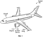
- FIG. 1 depicts a system 100 of an aircraft 101 (e.g., an airplane including wings 102).
- the aircraft 101 can be any vehicle that is able to fly by gaining support from air to counter gravity through static lift, dynamic lift, and/or downward thrust.
- the wings 102 are airfoils that helps lift the 'heavier-than-air aircraft' 101.
- the system 100 within the aircraft 101 also may include n engine 112.
- the engine 112 can be a source of mechanical energy, examples of which include at least gas and jet turbine engines.
- the engine 112 can be located on the wing 102 of the aircraft 101 and can include an air-start device 115.
- the air-start device 115 is a power source used to provide the initial rotation to start the engine 112.
- FIG. 2 a perspective view of a system 200 comprising a baffle design 210 accordingly to background art is provided.
- the system 200 is an example of the air-start device 115 of FIG. 1 .
- the baffle design 210 includes one or more individual baffles (as shown three baffles 211A, 211B, and 211C), each of which is mounted in parallel to a mounting face 220.
- the mounting face 220 can be further held to a starter 221 by one or more mounting bolts 222.
- Each of the one or more individual baffles 211A, 211B, and 211C are further separated by spacers 230.
- a mounting bolt 240 is used to position the baffles 210 and the spacers 230 to the mounting face 220.
- a spacer stack can include a number of spacers equal to the number of the one or more baffles 211A, 211B, and 211C plus one.
- the parts for the baffle design 210 can include one or more baffles (e.g., the three baffles 211A, 211B, and 211C shown), 8-12 mounting bolts 240, and 32-48 or more spacers 230.
- FIG. 3 is a perspective view of a system 300 comprising a baffle 310 accordingly to one or more embodiments.
- the system 300 is an example of the air-start device 115 of FIG. 1 .
- the system 300 of FIG. 3 will further be described with respect to FIGS. 4-5 , with the numerical identifiers being reused for brevity.
- the baffle 310 can be a one piece design that replaces the multiple individual baffles 211A, 211B, and 211C, the mounting face 220, and the spacers 230 of the baffle design 210 of FIG. 2 .
- the baffle 310 utilizes the mounting bolts 222 to be held against the starter 221 (e.g., share a same mounting configuration as the mounting face 220).
- FIG. 4 is a perspective view of the baffle 310 of the system of FIG. 3 according to one or more embodiments
- FIG. 5 is a cross section of the system 300 of FIG. 3 along demarcation A-A according to one or more embodiments.
- the baffle 310 can be a one piece design that includes a cylindrical baffle section 420 with a repeating pattern of holes 430 (e.g., elliptical shape, cylindrical shape, slotted shape, or otherwise) and is integral to a split line retaining section 440.
- the split line retaining section 440 includes one or more mounting bosses 450 that align with the mounting bolts 222.
- the one or more mounting bosses 450 are representative of one or more tabs, flanges, collars, ribs, rims, or any other projecting object, serving to attach the baffle 310 to the starter 221.
- the repeating pattern of holes 430 enable exhaust air to pass, yet still contain fragments that may come through the exhaust path, and prevent any foreign object debris from entering the starter 221 through an exhaust 550 (e.g., which begins to the right side of turbine rotor as shown in FIG. 5 ).
- the repeating pattern of holes 430 may be designed to provide a fix area, which is a sum of a surface area of each hole 430. This fixed area provides exhaust air to pass through the exhaust 550 at a rate needed for the system 300 to operate. Simultaneously, because each of the repeating pattern of holes 430 is individually sized fragments that may come through the exhaust 550 are contained and foreign object debris external to the system 300 are prevented from entering the starter 221.
- the baffle 310 is configurable during manufacturing.
- the baffle 310 can be sculpted through laser jet cutting from a single piece of material (metal or otherwise).
- One or more of the holes 430 can be individually configured by size, shape, and/or location.
- each of the one or more of the holes 430 can be a quarter inch in diameter and/or across (e.g., in either the X or Y direction as shown in FIG. 4 ) to limit size of debris that can leave the starter 221.
- the baffle 310 can be manufactured with cylindrical shaped holes, crescent shaped holes, and/or zigzag shaped holes.
- FIG. 6 depicts examples of hole designs for a baffle according to one or more embodiments.
- the one or more of the holes 430 can be a cylindrical shaped hole design 605, crescent shaped hole design 615, or zigzag shaped hole design 625.
- the number of holes 430 as well as their size dictates an air flow.
- the baffle 310 ensures that the air flow is not statistically significantly more restrictive than if the baffle 310 was not installed.
- the baffle 310 is configured to provide less than 1% difference (i.e., decrease) in torque output of the starter 221 (e.g., which results from flow restriction). In this regard, the baffle 310 did not impact performance of the starter 221 from a flow perspective, while greatly improving assembly, increasing strength, and decreasing weight of the system 300.
- the technical effects and benefits of the baffle 310 greatly simplify an assembly process of the system 300. For instance, instead of needing to mount multiple exhaust baffles, align spacers, and configure the bolt assemblies, the baffle 310 as a retaining plate is installed. Further, the baffle 310 also allows for weight savings (by the elimination of multiple pieces) and strength advantages (given the integrated design; e.g., the structure of the baffle 310 is stronger and will resist cracking and having aerodynamic forces exciting it's resonant mode). The technical effects and benefits of the baffle 310 also include enabling a completely customizable configuration of holes to create an asymmetric radial exhaust flow that prevents direct exhaust impingement on sensitive components, while not degrading overall exhaust flow.
Landscapes
- Engineering & Computer Science (AREA)
- Chemical & Material Sciences (AREA)
- Combustion & Propulsion (AREA)
- Mechanical Engineering (AREA)
- General Engineering & Computer Science (AREA)
- Structures Of Non-Positive Displacement Pumps (AREA)
- Exhaust Gas After Treatment (AREA)
Abstract
Description
- An aircraft generally has a starter associated with its engine. The starter assists the engine with turning on. A starter can include an exhaust baffle design on an exhaust path to prevent debris from exciting or entering the starter. Current exhaust baffle designs have many parts and are labor intensive to assemble. Further, due to the complex nature of assembly, current exhaust baffle designs are susceptible to cracking during use.
- In accordance with one or more embodiments, a baffle is provided herein. The baffle includes a cylindrical baffle section. The cylindrical baffle section includes one or more holes. The baffle also includes a split line retaining section. The split line retaining section includes one or more mounting bosses. Each of the one or more mounting bosses receives one or more mounting bolts.
- In accordance with one or more embodiments or the baffle embodiment above, the baffle includes a one piece design
- In accordance with one or more embodiments or any of the baffle embodiments above, the baffle can utilize the one or more mounting bolts to position the baffle against a starter.
- In accordance with one or more embodiments or any of the baffle embodiments above, the cylindrical baffle section can include a repeating pattern of the one or more holes.
- In accordance with one or more embodiments or any of the baffle embodiments above, each hole of the one or more holes can include a cylindrical shape or a slotted shape.
- In accordance with one or more embodiments or any of the baffle embodiments above, each hole of the one or more holes can be a quarter inch across.
- In accordance with one or more embodiments or any of the baffle embodiments above, the one or more holes can enable exhaust air to pass out of a starter.
- In accordance with one or more embodiments or any of the baffle embodiments above, each hole of the one or more holes can include a crescent shape or zigzag shape.
- In accordance with one or more embodiments or any of the baffle embodiments above, the baffle can be incorporated into an air-start device.
- In accordance with one or more embodiments or any of the baffle embodiments above, an engine of an aircraft can include the air-start device.
- In accordance with one or more embodiments, an air-start device is provided. The air-start device includes a starter and a baffle design configured over an exhaust path of the starter. The baffle design includes a cylindrical baffle section comprising one or more holes and a split line retaining section comprising one or more mounting bosses for receiving one or more mounting bolts. The baffle design utilizes the one or more mounting bolts to position the baffle against the starter.
- In accordance with one or more embodiments or the air-start device embodiment above, the baffle can include a one piece design.
- In accordance with one or more embodiments or any of the air-start device embodiments above, the cylindrical baffle section can include a repeating pattern of the one or more holes.
- In accordance with one or more embodiments or any of the air-start device embodiments above, each hole of the one or more holes can include a cylindrical shape or a slotted shape.
- In accordance with one or more embodiments or any of the air-start device embodiments above, each hole of the one or more holes can be a quarter inch across.
- In accordance with one or more embodiments or any of the air-start device embodiments above, the one or more holes can enable exhaust air to pass out of the starter.
- In accordance with one or more embodiments or any of the air-start device embodiments above, each hole of the one or more holes can include a crescent shape or zigzag shape.
- The following descriptions should not be considered limiting in any way. With reference to the accompanying drawings, like elements are numbered alike:
-
FIG. 1 depicts a system of an aircraft according to one or more embodiments; -
FIG. 2 is a perspective view of a system comprising a current baffle design accordingly to background art; -
FIG. 3 is a perspective view of a system comprising a baffle accordingly to one or more embodiments; -
FIG. 4 is a perspective view of the baffle of the system ofFIG. 3 according to one or more embodiments; -
FIG. 5 is a cross section of the system ofFIG. 3 according to one or more embodiments; -
FIG. 6 depicts examples of hole designs for a baffle according to one or more embodiments. - A detailed description of one or more embodiments of the disclosed apparatus and method are presented herein by way of exemplification and not limitation with reference to the Figures.
-
FIG. 1 depicts asystem 100 of an aircraft 101 (e.g., an airplane including wings 102). Theaircraft 101 can be any vehicle that is able to fly by gaining support from air to counter gravity through static lift, dynamic lift, and/or downward thrust. Thewings 102 are airfoils that helps lift the 'heavier-than-air aircraft' 101. - The
system 100, within theaircraft 101 also may includen engine 112. Theengine 112 can be a source of mechanical energy, examples of which include at least gas and jet turbine engines. Theengine 112 can be located on thewing 102 of theaircraft 101 and can include an air-start device 115. The air-start device 115 is a power source used to provide the initial rotation to start theengine 112. - Turning to
FIG. 2 , a perspective view of asystem 200 comprising abaffle design 210 accordingly to background art is provided. Thesystem 200 is an example of the air-start device 115 ofFIG. 1 . Thebaffle design 210 includes one or more individual baffles (as shown threebaffles mounting face 220. The mountingface 220 can be further held to astarter 221 by one ormore mounting bolts 222. Each of the one or moreindividual baffles spacers 230. For each set of spacers (e.g., referred to as a spacer stack), amounting bolt 240 is used to position thebaffles 210 and thespacers 230 to the mountingface 220. In this regard, for eachmounting bolt 240, a spacer stack can include a number of spacers equal to the number of the one ormore baffles system 200 typically includes between 8-12mounting bolts 240, the parts for thebaffle design 210 can include one or more baffles (e.g., the threebaffles mounting bolts 240, and 32-48 ormore spacers 230. -
FIG. 3 is a perspective view of asystem 300 comprising abaffle 310 accordingly to one or more embodiments. Thesystem 300 is an example of the air-start device 115 ofFIG. 1 . Thesystem 300 ofFIG. 3 will further be described with respect toFIGS. 4-5 , with the numerical identifiers being reused for brevity. Thebaffle 310 can be a one piece design that replaces the multipleindividual baffles mounting face 220, and thespacers 230 of thebaffle design 210 ofFIG. 2 . In this regard, thebaffle 310 utilizes themounting bolts 222 to be held against the starter 221 (e.g., share a same mounting configuration as the mounting face 220). Note thatFIG. 4 is a perspective view of thebaffle 310 of the system ofFIG. 3 according to one or more embodiments, and note thatFIG. 5 is a cross section of thesystem 300 ofFIG. 3 along demarcation A-A according to one or more embodiments. - Turning to
FIG. 4 , thebaffle 310 can be a one piece design that includes acylindrical baffle section 420 with a repeating pattern of holes 430 (e.g., elliptical shape, cylindrical shape, slotted shape, or otherwise) and is integral to a splitline retaining section 440. Further, the splitline retaining section 440 includes one or more mountingbosses 450 that align with the mountingbolts 222. The one or more mountingbosses 450 are representative of one or more tabs, flanges, collars, ribs, rims, or any other projecting object, serving to attach thebaffle 310 to thestarter 221. The repeating pattern ofholes 430 enable exhaust air to pass, yet still contain fragments that may come through the exhaust path, and prevent any foreign object debris from entering thestarter 221 through an exhaust 550 (e.g., which begins to the right side of turbine rotor as shown inFIG. 5 ). - For example, the repeating pattern of
holes 430 may be designed to provide a fix area, which is a sum of a surface area of eachhole 430. This fixed area provides exhaust air to pass through theexhaust 550 at a rate needed for thesystem 300 to operate. Simultaneously, because each of the repeating pattern ofholes 430 is individually sized fragments that may come through theexhaust 550 are contained and foreign object debris external to thesystem 300 are prevented from entering thestarter 221. - The
baffle 310 is configurable during manufacturing. For example, thebaffle 310 can be sculpted through laser jet cutting from a single piece of material (metal or otherwise). One or more of theholes 430 can be individually configured by size, shape, and/or location. For example, each of the one or more of theholes 430 can be a quarter inch in diameter and/or across (e.g., in either the X or Y direction as shown inFIG. 4 ) to limit size of debris that can leave thestarter 221. In accordance with one or more embodiments, thebaffle 310 can be manufactured with cylindrical shaped holes, crescent shaped holes, and/or zigzag shaped holes. For example,FIG. 6 depicts examples of hole designs for a baffle according to one or more embodiments. As shown, the one or more of theholes 430 can be a cylindrical shapedhole design 605, crescent shapedhole design 615, or zigzag shaped hole design 625. The number ofholes 430 as well as their size dictates an air flow. Thebaffle 310 ensures that the air flow is not statistically significantly more restrictive than if thebaffle 310 was not installed. In accordance with one or more embodiments, thebaffle 310 is configured to provide less than 1% difference (i.e., decrease) in torque output of the starter 221 (e.g., which results from flow restriction). In this regard, thebaffle 310 did not impact performance of thestarter 221 from a flow perspective, while greatly improving assembly, increasing strength, and decreasing weight of thesystem 300. - The technical effects and benefits of the
baffle 310 greatly simplify an assembly process of thesystem 300. For instance, instead of needing to mount multiple exhaust baffles, align spacers, and configure the bolt assemblies, thebaffle 310 as a retaining plate is installed. Further, thebaffle 310 also allows for weight savings (by the elimination of multiple pieces) and strength advantages (given the integrated design; e.g., the structure of thebaffle 310 is stronger and will resist cracking and having aerodynamic forces exciting it's resonant mode). The technical effects and benefits of thebaffle 310 also include enabling a completely customizable configuration of holes to create an asymmetric radial exhaust flow that prevents direct exhaust impingement on sensitive components, while not degrading overall exhaust flow. - The term "about" is intended to include the degree of error associated with measurement of the particular quantity based upon the equipment available at the time of filing the application.
- The terminology used herein is for the purpose of describing particular embodiments only and is not intended to be limiting of the present disclosure. As used herein, the singular forms "a", "an" and "the" are intended to include the plural forms as well, unless the context clearly indicates otherwise. It will be further understood that the terms "comprises" and/or "comprising," when used in this specification, specify the presence of stated features, integers, steps, operations, elements, and/or components, but do not preclude the presence or addition of one or more other features, integers, steps, operations, element components, and/or groups thereof.
- While the present disclosure has been described with reference to an exemplary embodiment or embodiments, it will be understood by those skilled in the art that various changes may be made and equivalents may be substituted for elements thereof without departing from the scope of the present disclosure as defined by the claims. In addition, many modifications may be made to adapt a particular situation or material to the teachings of the present disclosure without departing from the essential scope thereof. Therefore, it is intended that the present disclosure not be limited to the particular embodiment disclosed as the best mode contemplated for carrying out this present disclosure, but that the present disclosure will include all embodiments falling within the scope of the claims.
Claims (11)
- A baffle (310) comprising:a cylindrical baffle section (420) comprising one or more holes (430); anda split line retaining section (440) comprising one or more mounting bosses (450) for receiving one or more mounting bolts.
- The baffle of claim 1, wherein the baffle comprises a one piece design.
- The baffle of claim 1 or 2, wherein the baffle utilizes the one or more mounting bolts to position the baffle against a starter (221).
- The baffle of any preceding claim, wherein the cylindrical baffle section comprises a repeating pattern of the one or more holes.
- The baffle of any preceding claim, wherein each hole of the one or more holes comprises a cylindrical shape or a slotted shape.
- The baffle of claim 5, wherein each hole of the one or more holes is a quarter inch (6.35mm) across.
- The baffle of any preceding claim, wherein the one or more holes enable exhaust air to pass out of a starter (221).
- The baffle of any of claims 1 to 4, wherein each hole of the one or more holes comprises a crescent shape or zigzag shape.
- The baffle of claim 1, wherein the baffle is incorporated into an air-start device (115).
- The baffle of claim 9, wherein an engine of an aircraft (101) comprises the air-start device.
- An air-start device (115) comprising:a starter (221); anda baffle design (115) configured over an exhaust path of the starter, the baffle design comprising the baffle of any preceding claim,wherein the baffle design utilizes the one or more mounting bolts (240) to position the baffle against the starter.
Applications Claiming Priority (1)
| Application Number | Priority Date | Filing Date | Title |
|---|---|---|---|
| US16/811,915 US11384691B2 (en) | 2020-03-06 | 2020-03-06 | Integrated exhaust baffle and split line retaining plate |
Publications (2)
| Publication Number | Publication Date |
|---|---|
| EP3875743A1 true EP3875743A1 (en) | 2021-09-08 |
| EP3875743B1 EP3875743B1 (en) | 2025-04-23 |
Family
ID=74856675
Family Applications (1)
| Application Number | Title | Priority Date | Filing Date |
|---|---|---|---|
| EP21160309.7A Active EP3875743B1 (en) | 2020-03-06 | 2021-03-02 | Integrated exhaust baffle and split line retaining plate |
Country Status (2)
| Country | Link |
|---|---|
| US (1) | US11384691B2 (en) |
| EP (1) | EP3875743B1 (en) |
Citations (2)
| Publication number | Priority date | Publication date | Assignee | Title |
|---|---|---|---|---|
| US20030017045A1 (en) * | 2001-07-17 | 2003-01-23 | Robert Telakowski | Turbine no-load speed limiter |
| US20120114475A1 (en) * | 2010-11-10 | 2012-05-10 | Hamilton Sundstrand Corporation | Air turbine starter one-piece air exit port baffle |
Family Cites Families (5)
| Publication number | Priority date | Publication date | Assignee | Title |
|---|---|---|---|---|
| US3838749A (en) * | 1973-02-15 | 1974-10-01 | H Johnson | Pulse noise reducer |
| US4271674A (en) * | 1974-10-17 | 1981-06-09 | United Technologies Corporation | Premix combustor assembly |
| US5601406A (en) * | 1994-12-21 | 1997-02-11 | Alliedsignal Inc. | Centrifugal compressor hub containment assembly |
| US6533541B1 (en) * | 2001-12-04 | 2003-03-18 | Honeywell International, Inc. | High energy particle arrestor for air turbine starters |
| FR2941743B1 (en) | 2009-02-05 | 2011-03-04 | Microturbo | AIR STARTER FOR TURBOMACHINE. |
-
2020
- 2020-03-06 US US16/811,915 patent/US11384691B2/en active Active
-
2021
- 2021-03-02 EP EP21160309.7A patent/EP3875743B1/en active Active
Patent Citations (2)
| Publication number | Priority date | Publication date | Assignee | Title |
|---|---|---|---|---|
| US20030017045A1 (en) * | 2001-07-17 | 2003-01-23 | Robert Telakowski | Turbine no-load speed limiter |
| US20120114475A1 (en) * | 2010-11-10 | 2012-05-10 | Hamilton Sundstrand Corporation | Air turbine starter one-piece air exit port baffle |
Also Published As
| Publication number | Publication date |
|---|---|
| US11384691B2 (en) | 2022-07-12 |
| US20210277830A1 (en) | 2021-09-09 |
| EP3875743B1 (en) | 2025-04-23 |
Similar Documents
| Publication | Publication Date | Title |
|---|---|---|
| CN109415940B (en) | Metal leading edge for composite fan blade | |
| JP5982498B2 (en) | Wing for wake desensitization and manufacturing method thereof | |
| US5667361A (en) | Flutter resistant blades, vanes and arrays thereof for a turbomachine | |
| US8616854B2 (en) | Nose cone assembly | |
| RU2525363C2 (en) | Turbine wheel and turbomachine with such wheel | |
| EP2096029A2 (en) | Nose cone assembly and gas turbine engine comprising such an assemby | |
| EP3318482B1 (en) | Snap fit nose cone assembly | |
| EP3034804B1 (en) | Pre-diffuser strut for gas turbine engine | |
| EP3318738B1 (en) | Nose cone assembly without fasteners | |
| EP3318737B1 (en) | Low weight nose cone assembly | |
| CA2845218C (en) | Compressor stator | |
| CN120322378A (en) | Aero propulsion with improved integration | |
| CN110273714B (en) | Collar support assembly for an airfoil | |
| CN106121746A (en) | Compound diverter lip for axial flow turbine machinery compressor | |
| EP3940199A1 (en) | System and method for air injection passageway integration and optimization in turbomachinery | |
| EP3875743B1 (en) | Integrated exhaust baffle and split line retaining plate | |
| EP3051061B1 (en) | Gas turbine engine disk balancing system | |
| EP3919724A1 (en) | Characteristic distribution for rotor blade of booster rotor | |
| EP3919723A1 (en) | Characteristic distribution for rotor blade of booster rotor | |
| EP2855896B1 (en) | Stator vane mistake proofing | |
| CN120379897A (en) | Aeronautical propeller with improved aero-acoustic | |
| US10024165B2 (en) | De-oiler balance weights for turbomachine rotors and systems for removing excess oil from turbomachine rotors | |
| EP2907970B1 (en) | Misaligned concentric airfoil assembly and method of misaligning said assembly | |
| CN118423308A (en) | Segmented leading edge guard | |
| US11143103B2 (en) | Nose cone and fan assembly |
Legal Events
| Date | Code | Title | Description |
|---|---|---|---|
| PUAI | Public reference made under article 153(3) epc to a published international application that has entered the european phase |
Free format text: ORIGINAL CODE: 0009012 |
|
| STAA | Information on the status of an ep patent application or granted ep patent |
Free format text: STATUS: THE APPLICATION HAS BEEN PUBLISHED |
|
| AK | Designated contracting states |
Kind code of ref document: A1 Designated state(s): AL AT BE BG CH CY CZ DE DK EE ES FI FR GB GR HR HU IE IS IT LI LT LU LV MC MK MT NL NO PL PT RO RS SE SI SK SM TR |
|
| STAA | Information on the status of an ep patent application or granted ep patent |
Free format text: STATUS: REQUEST FOR EXAMINATION WAS MADE |
|
| 17P | Request for examination filed |
Effective date: 20220222 |
|
| RBV | Designated contracting states (corrected) |
Designated state(s): AL AT BE BG CH CY CZ DE DK EE ES FI FR GB GR HR HU IE IS IT LI LT LU LV MC MK MT NL NO PL PT RO RS SE SI SK SM TR |
|
| STAA | Information on the status of an ep patent application or granted ep patent |
Free format text: STATUS: EXAMINATION IS IN PROGRESS |
|
| 17Q | First examination report despatched |
Effective date: 20230314 |
|
| GRAP | Despatch of communication of intention to grant a patent |
Free format text: ORIGINAL CODE: EPIDOSNIGR1 |
|
| STAA | Information on the status of an ep patent application or granted ep patent |
Free format text: STATUS: GRANT OF PATENT IS INTENDED |
|
| INTG | Intention to grant announced |
Effective date: 20241108 |
|
| GRAS | Grant fee paid |
Free format text: ORIGINAL CODE: EPIDOSNIGR3 |
|
| GRAA | (expected) grant |
Free format text: ORIGINAL CODE: 0009210 |
|
| STAA | Information on the status of an ep patent application or granted ep patent |
Free format text: STATUS: THE PATENT HAS BEEN GRANTED |
|
| AK | Designated contracting states |
Kind code of ref document: B1 Designated state(s): AL AT BE BG CH CY CZ DE DK EE ES FI FR GB GR HR HU IE IS IT LI LT LU LV MC MK MT NL NO PL PT RO RS SE SI SK SM TR |
|
| REG | Reference to a national code |
Ref country code: GB Ref legal event code: FG4D |
|
| REG | Reference to a national code |
Ref country code: CH Ref legal event code: EP |
|
| REG | Reference to a national code |
Ref country code: DE Ref legal event code: R096 Ref document number: 602021029450 Country of ref document: DE |
|
| REG | Reference to a national code |
Ref country code: IE Ref legal event code: FG4D |
|
| REG | Reference to a national code |
Ref country code: NL Ref legal event code: MP Effective date: 20250423 |
|
| PG25 | Lapsed in a contracting state [announced via postgrant information from national office to epo] |
Ref country code: NL Free format text: LAPSE BECAUSE OF FAILURE TO SUBMIT A TRANSLATION OF THE DESCRIPTION OR TO PAY THE FEE WITHIN THE PRESCRIBED TIME-LIMIT Effective date: 20250423 |
|
| REG | Reference to a national code |
Ref country code: AT Ref legal event code: MK05 Ref document number: 1787951 Country of ref document: AT Kind code of ref document: T Effective date: 20250423 |
|
| PG25 | Lapsed in a contracting state [announced via postgrant information from national office to epo] |
Ref country code: FI Free format text: LAPSE BECAUSE OF FAILURE TO SUBMIT A TRANSLATION OF THE DESCRIPTION OR TO PAY THE FEE WITHIN THE PRESCRIBED TIME-LIMIT Effective date: 20250423 Ref country code: PT Free format text: LAPSE BECAUSE OF FAILURE TO SUBMIT A TRANSLATION OF THE DESCRIPTION OR TO PAY THE FEE WITHIN THE PRESCRIBED TIME-LIMIT Effective date: 20250825 Ref country code: ES Free format text: LAPSE BECAUSE OF FAILURE TO SUBMIT A TRANSLATION OF THE DESCRIPTION OR TO PAY THE FEE WITHIN THE PRESCRIBED TIME-LIMIT Effective date: 20250423 |
|
| REG | Reference to a national code |
Ref country code: LT Ref legal event code: MG9D |
|
| PG25 | Lapsed in a contracting state [announced via postgrant information from national office to epo] |
Ref country code: NO Free format text: LAPSE BECAUSE OF FAILURE TO SUBMIT A TRANSLATION OF THE DESCRIPTION OR TO PAY THE FEE WITHIN THE PRESCRIBED TIME-LIMIT Effective date: 20250723 Ref country code: GR Free format text: LAPSE BECAUSE OF FAILURE TO SUBMIT A TRANSLATION OF THE DESCRIPTION OR TO PAY THE FEE WITHIN THE PRESCRIBED TIME-LIMIT Effective date: 20250724 |
|
| PG25 | Lapsed in a contracting state [announced via postgrant information from national office to epo] |
Ref country code: PL Free format text: LAPSE BECAUSE OF FAILURE TO SUBMIT A TRANSLATION OF THE DESCRIPTION OR TO PAY THE FEE WITHIN THE PRESCRIBED TIME-LIMIT Effective date: 20250423 |
|
| PG25 | Lapsed in a contracting state [announced via postgrant information from national office to epo] |
Ref country code: BG Free format text: LAPSE BECAUSE OF FAILURE TO SUBMIT A TRANSLATION OF THE DESCRIPTION OR TO PAY THE FEE WITHIN THE PRESCRIBED TIME-LIMIT Effective date: 20250423 |
|
| PG25 | Lapsed in a contracting state [announced via postgrant information from national office to epo] |
Ref country code: HR Free format text: LAPSE BECAUSE OF FAILURE TO SUBMIT A TRANSLATION OF THE DESCRIPTION OR TO PAY THE FEE WITHIN THE PRESCRIBED TIME-LIMIT Effective date: 20250423 |
|
| PG25 | Lapsed in a contracting state [announced via postgrant information from national office to epo] |
Ref country code: AT Free format text: LAPSE BECAUSE OF FAILURE TO SUBMIT A TRANSLATION OF THE DESCRIPTION OR TO PAY THE FEE WITHIN THE PRESCRIBED TIME-LIMIT Effective date: 20250423 |
|
| PG25 | Lapsed in a contracting state [announced via postgrant information from national office to epo] |
Ref country code: RS Free format text: LAPSE BECAUSE OF FAILURE TO SUBMIT A TRANSLATION OF THE DESCRIPTION OR TO PAY THE FEE WITHIN THE PRESCRIBED TIME-LIMIT Effective date: 20250723 |
|
| PG25 | Lapsed in a contracting state [announced via postgrant information from national office to epo] |
Ref country code: IS Free format text: LAPSE BECAUSE OF FAILURE TO SUBMIT A TRANSLATION OF THE DESCRIPTION OR TO PAY THE FEE WITHIN THE PRESCRIBED TIME-LIMIT Effective date: 20250823 |
|
| PG25 | Lapsed in a contracting state [announced via postgrant information from national office to epo] |
Ref country code: LV Free format text: LAPSE BECAUSE OF FAILURE TO SUBMIT A TRANSLATION OF THE DESCRIPTION OR TO PAY THE FEE WITHIN THE PRESCRIBED TIME-LIMIT Effective date: 20250423 |
|
| PG25 | Lapsed in a contracting state [announced via postgrant information from national office to epo] |
Ref country code: SM Free format text: LAPSE BECAUSE OF FAILURE TO SUBMIT A TRANSLATION OF THE DESCRIPTION OR TO PAY THE FEE WITHIN THE PRESCRIBED TIME-LIMIT Effective date: 20250423 Ref country code: DK Free format text: LAPSE BECAUSE OF FAILURE TO SUBMIT A TRANSLATION OF THE DESCRIPTION OR TO PAY THE FEE WITHIN THE PRESCRIBED TIME-LIMIT Effective date: 20250423 |
|
| PG25 | Lapsed in a contracting state [announced via postgrant information from national office to epo] |
Ref country code: CZ Free format text: LAPSE BECAUSE OF FAILURE TO SUBMIT A TRANSLATION OF THE DESCRIPTION OR TO PAY THE FEE WITHIN THE PRESCRIBED TIME-LIMIT Effective date: 20250423 |
|
| PG25 | Lapsed in a contracting state [announced via postgrant information from national office to epo] |
Ref country code: EE Free format text: LAPSE BECAUSE OF FAILURE TO SUBMIT A TRANSLATION OF THE DESCRIPTION OR TO PAY THE FEE WITHIN THE PRESCRIBED TIME-LIMIT Effective date: 20250423 |
|
| REG | Reference to a national code |
Ref country code: DE Ref legal event code: R097 Ref document number: 602021029450 Country of ref document: DE |
|
| PG25 | Lapsed in a contracting state [announced via postgrant information from national office to epo] |
Ref country code: RO Free format text: LAPSE BECAUSE OF FAILURE TO SUBMIT A TRANSLATION OF THE DESCRIPTION OR TO PAY THE FEE WITHIN THE PRESCRIBED TIME-LIMIT Effective date: 20250423 Ref country code: SK Free format text: LAPSE BECAUSE OF FAILURE TO SUBMIT A TRANSLATION OF THE DESCRIPTION OR TO PAY THE FEE WITHIN THE PRESCRIBED TIME-LIMIT Effective date: 20250423 |
|
| PG25 | Lapsed in a contracting state [announced via postgrant information from national office to epo] |
Ref country code: IT Free format text: LAPSE BECAUSE OF FAILURE TO SUBMIT A TRANSLATION OF THE DESCRIPTION OR TO PAY THE FEE WITHIN THE PRESCRIBED TIME-LIMIT Effective date: 20250423 |
|
| PLBE | No opposition filed within time limit |
Free format text: ORIGINAL CODE: 0009261 |
|
| STAA | Information on the status of an ep patent application or granted ep patent |
Free format text: STATUS: NO OPPOSITION FILED WITHIN TIME LIMIT |
|
| REG | Reference to a national code |
Ref country code: CH Ref legal event code: L10 Free format text: ST27 STATUS EVENT CODE: U-0-0-L10-L00 (AS PROVIDED BY THE NATIONAL OFFICE) Effective date: 20260304 |
|
| 26N | No opposition filed |
Effective date: 20260126 |
|
| PGFP | Annual fee paid to national office [announced via postgrant information from national office to epo] |
Ref country code: FR Payment date: 20260219 Year of fee payment: 6 |