EP3875413A1 - Hose box - Google Patents
Hose box Download PDFInfo
- Publication number
- EP3875413A1 EP3875413A1 EP20160457.6A EP20160457A EP3875413A1 EP 3875413 A1 EP3875413 A1 EP 3875413A1 EP 20160457 A EP20160457 A EP 20160457A EP 3875413 A1 EP3875413 A1 EP 3875413A1
- Authority
- EP
- European Patent Office
- Prior art keywords
- hose
- belt
- drive
- pulley
- box
- Prior art date
- Legal status (The legal status is an assumption and is not a legal conclusion. Google has not performed a legal analysis and makes no representation as to the accuracy of the status listed.)
- Granted
Links
Images


Classifications
-
- B—PERFORMING OPERATIONS; TRANSPORTING
- B65—CONVEYING; PACKING; STORING; HANDLING THIN OR FILAMENTARY MATERIAL
- B65H—HANDLING THIN OR FILAMENTARY MATERIAL, e.g. SHEETS, WEBS, CABLES
- B65H75/00—Storing webs, tapes, or filamentary material, e.g. on reels
- B65H75/02—Cores, formers, supports, or holders for coiled, wound, or folded material, e.g. reels, spindles, bobbins, cop tubes, cans, mandrels or chucks
- B65H75/34—Cores, formers, supports, or holders for coiled, wound, or folded material, e.g. reels, spindles, bobbins, cop tubes, cans, mandrels or chucks specially adapted or mounted for storing and repeatedly paying-out and re-storing lengths of material provided for particular purposes, e.g. anchored hoses, power cables
- B65H75/38—Cores, formers, supports, or holders for coiled, wound, or folded material, e.g. reels, spindles, bobbins, cop tubes, cans, mandrels or chucks specially adapted or mounted for storing and repeatedly paying-out and re-storing lengths of material provided for particular purposes, e.g. anchored hoses, power cables involving the use of a core or former internal to, and supporting, a stored package of material
- B65H75/44—Constructional details
- B65H75/4402—Guiding arrangements to control paying-out and re-storing of the material
- B65H75/4405—Traversing devices; means for orderly arranging the material on the drum
- B65H75/4407—Traversing devices; means for orderly arranging the material on the drum positively driven, e.g. by a transmission between the drum and the traversing device
-
- B—PERFORMING OPERATIONS; TRANSPORTING
- B29—WORKING OF PLASTICS; WORKING OF SUBSTANCES IN A PLASTIC STATE IN GENERAL
- B29D—PRODUCING PARTICULAR ARTICLES FROM PLASTICS OR FROM SUBSTANCES IN A PLASTIC STATE
- B29D29/00—Producing belts or bands
- B29D29/08—Toothed driving belts
-
- B—PERFORMING OPERATIONS; TRANSPORTING
- B65—CONVEYING; PACKING; STORING; HANDLING THIN OR FILAMENTARY MATERIAL
- B65H—HANDLING THIN OR FILAMENTARY MATERIAL, e.g. SHEETS, WEBS, CABLES
- B65H2701/00—Handled material; Storage means
- B65H2701/30—Handled filamentary material
- B65H2701/33—Hollow or hose-like material
Definitions
- the present disclosure relates to a hose box. More specifically, the present disclosure relates to the hose box which provides an ergonomic profile of ease of handling of a hose.
- a hose box is a device fitted outdoors or indoors to hold a hose.
- the wound hose may be taken out of the hose box as per the requirements.
- the hose box includes an apparatus to allow mechanical winding or unwinding of the hose.
- the hose box may have some additional sources to provide mechanical assistance for the adjustments of the hose.
- the apparatus for mechanical winding or unwinding of the hose may be bulky or uncompacted.
- Working with the hose box may include unrequired length of a belt (necessary) to drive a hose guide.
- placing of a gear to the central axis of the hose may require long belt to drive the hose guide.
- the '195 reference provides a cable reel for a small mobile device.
- the cable reel includes a cable drum.
- An axis of the cable drum is arranged horizontally mounted on the small mobile device such that it can pivot about a vertical axis.
- the cable drum is driven by a separate electric motor which is supplied via a cable of the cable drum, in parallel with the drive motor of the small mobile device.
- a switching-off device switches the electric motor off when the cable which is wound up by the cable drum, is stressed taut.
- the cable is guided onto the cable drum via a guidance device.
- the guidance device is moved in a reciprocating manner, over the width of the cable drum, by the electric motor.
- the '195 reference seems short of disclosing a simple, compact arrangement for winding of the cable.
- the hose box includes a hose guide pulley.
- the hose guide pulley allows a lateral movement of a hose guide to wind a hose within the hose box.
- a first pulley is drivingly coupled to the hose box.
- the hose box further includes a belt-drive.
- the belt-drive is operatively coupled with the first pulley and the hose guide pulley.
- the hose box is characterized in that an annular gear rotates during winding of the hose around a central axis and operatively coupled to the first pulley.
- the first pulley is disposed at a radial offset from the central axis of the hose box.
- the first pulley is located between the hose guide pulley and the central axis of the hose box.
- the positioning of the first pulley may allow reduction of length of the belt-drive.
- the hose box includes a control unit. This may allow an automatic check on motion of the belt-drive.
- the belt-drive is made of a material selected from one or more of polymers, plastics, and metals. This may provide the belt-drive with characteristic features such as flexibility, cost efficiency, and heat resistant properties.
- the belt-drive is one or more of a toothed belt, a V-belt, a round belt, and a flat belt. This may allow better delivery of power necessary for proper functioning of the hose guide.
- the hose guide pulley is constructed to deflect and guide the hose to the direction of the hose guide moves. This may provide an efficient pulling out of the hose out of the hose box.
- the hose box further includes a stopper. This may allow the user to hold the hose.
- a belt-drive for a hose box is provided. This may allow to transmit power more efficiently.
- the belt-drive is manufactured by three-dimensional printing.
- Use of three-dimensional printing provides versatility of using different materials along with reduced lead-time in manufacturing and design of the belt-drive.
- a data file having pre-stored instructions to print the belt-drive using a three-dimensional (3-D) printer. This may allow to manufacture the belt-drive using three-dimensional printing.
- the belt-drive is presented in digital format. This may help in customization of the belt-drive.
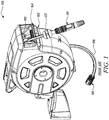
- FIG. 1 illustrates a conventional hose box 100 as per the present disclosure.
- the conventional hose box 100 may be fitted outdoor or indoor, especially in gardens, hospitals, malls to bring folded hose into function as per the requirements.
- the conventional hose box 100 may be fixed or attached to a wall or a ground surface. This makes the conventional hose box 100 widely usable in outdoor and indoor applications.
- the conventional hose box 100 includes a housing 102.
- the conventional hose box 100 further includes a hose 104 wound on a reel 107 (shown in FIG. 2 ). In the depicted example the hose 104 is connected to a nozzle 110.
- a water supply hose 106 with a connector 105 is provided at the other extreme end of the conventional hose box 100.
- the connector 105 may be connected to any water source such as, but not limited to a tap, a hose, or a tank.
- the hose 104 is further connected to a stopper 122 that limits the automatic winding of the hose 104 onto the reel 107.
- the conventional hose box 100 includes a hose guide 108.
- FIG. 2 illustrates a partial side cross-sectional view of some relevant part of the spooling mechanics of the conventional hose box 100 together with a partial view of the hose 104 to be wound onto the reel 107.
- the conventional hose box 100 includes a hose guide pulley 112.
- the hose guide pulley 112 is drivingly coupled with the hose guide 108.
- the hose guide pulley 112 allows winding of the hose 104 within the conventional hose box 100.
- the hose 104 is connected to the nozzle 110 at one end of the hose 104.
- the conventional hose box 100 includes a first pulley 116 which is drivingly coupled to the reel 107 and parallel to the reel 107 rotates about rotational axis of the first pulley 116.
- a belt-drive 118 drivingly couples the first pulley 116 with the hose guide pulley 112.
- the conventional hose box 100 also includes the stopper 122 to limit a length of the hose 104.
- FIG. 3 illustrates a partial side view inside a hose box 200 according to the present disclosure.
- the hose box 200 includes a hose guide pulley 212.
- the hose guide pulley 212 is constructed to be drivingly connected to a hose guide 208 that guides a hose 204.
- the hose 204 is connected to a nozzle 210.
- the hose guide pulley 212 allows a lateral movement of the hose guide 208 to wind the hose 204 within the hose box 200.
- a first pulley 216 is drivingly coupled to a reel 207.
- the first pulley 216 includes a built-in belt pulley 217.
- the first pulley 216 and the built-in belt pulley 217 are drivingly coupled with the hose guide pulley 212 via a belt-drive 218.
- the reel 207 is connected to an annular gear 214.
- the annular gear 214 rotates during winding of the hose 204 around the rotational axis of the reel 207.
- the first pulley 216 is disposed at a radial offset from the central axis of the hose box 200 with the first pulley 216 being operatively coupled with the annular gear 214.
- the hose box 200 of the present disclosure has been shown without any housing in the present figure from clarity and explanation considerations.
- the hose box 200 may be assembled with any housing such as the housing 102, in accordance with implementation needs of the present disclosure.
- the first pulley 216 is located between the hose guide pulley 212 and the rotational axis of the reel 207. More preferably, the first pulley 216 is meshing with annular teeth 215. The position of the first pulley 216 allows reduction of a belt-drive length. This positioning of the first pulley 216 helps in saving materials and cost required for preparation of the belt-drive 218.
- the belt-drive 218 may be a round belt, a flat belt, a V-belt, a toothed belt. This allows better delivery of power necessary for proper functioning of the hose guide 208. Additionally, or alternatively, the hose guide pulley 212 and the built-in belt pulley 217 may be drivingly coupled by a roller chain, a detachable chain, a pintle chain, a silent chain, a leaf chain, a laminated metal chain and the like.
- FIG. 4 illustrates an embodiment of the first pulley 216 which includes a reel drive geometry 211 and a belt drive geometry 213.
- the belt drive geometry 213 is provided on the built-in belt pulley 217.
- the reel drive geometry 211 is engaged or meshed with the annular teeth 215.
- the reel drive geometry 211 and the annular teeth 215 are drivingly coupled with each other.
- the belt drive geometry 213 is further drivingly coupled with the belt-drive 218.
- the annular gear 214 starts to move.
- the movement generated in the annular gear 214 further provides mechanical assistance to the first pulley 216.
- the belt-drive 218 provides a link between the built-in belt pulley 217 and the hose guide pulley 212. Movement of the first pulley 216 is in line with the movement of the built-in belt pulley 217, thus corresponding to motion of the hose guide pulley 212.
- the belt-drive 218 may be manufactured using any material, such as polymers, metals, plastics, and the like. This provides the belt-drive 218 with characteristic features such as flexibility, cost efficiency, heat resistant properties. These properties eventually aim to move the hose guide pulley 212.
- the belt-drive 218 may be manufactured using any process, such as casting, molding, forging, fabrication, and the like.
- the belt-drive 218 may be manufactured by three-dimensional printing (also known as additive manufacturing or 3D printing).
- three-dimensional printing also known as additive manufacturing or 3D printing
- 3D printing provides versatility of using different materials along with low lead-time in manufacturing and design of the belt-drive 218.
- a data file is provided having pre-stored instructions to print the belt-drive 218 using a three-dimensional (3D) printer. This allows to manufacture the belt-drive 218 using three-dimensional printing.
- the belt-drive 218 is presented in digital format. This helps in customization of the belt-drive 218
- a counter may be provided with the hose box 200.
- the counter indicates the number of feet by which the hose 204 has been extended from the hose box 200.
- the counter makes the user aware about the length of rest of the hose 204 left in the hose box 200.
- a stopper 222 helps to limit the winding of the hose 204 into the hose box 200.
- the stopper 222 may prevent the complete winding of the hose 204.
- the stopper 222 may prevent complete back winding of the hose 204 into the hose box 200.
- the hose box 200 may be fixed or attached to a wall or a ground surface. This makes the hose box 200 widely usable in outdoor and indoor applications such as gardens, parks, buildings.
- the belt-drive 218 may be automatically controllable.
- the hose box 200 may have a control unit which may be configured to actuate actuators and/or sensors of the hose box 200.
- the control unit may instruct the actuators and/or sensors to process signal and move the belt-drive 218, thereby moving the hose guide pulley 212.
- a feedback loop may continuously monitor and adjust a hose length coming out of the hose box 200.
- the belt-drive 218 may be removably assembled to the first pulley 216 and the hose guide pulley 212. This may allow replacement of the belt-drive 218 during service time or as per the application requirements. Additionally, or alternatively, the belt-drive 218 may be rooted to the first pulley 216 and the hose guide pulley 212 which provides mechanical strength to the hose box 200.
Landscapes
- Engineering & Computer Science (AREA)
- Mechanical Engineering (AREA)
- Storing, Repeated Paying-Out, And Re-Storing Of Elongated Articles (AREA)
Abstract
Description
- The present disclosure relates to a hose box. More specifically, the present disclosure relates to the hose box which provides an ergonomic profile of ease of handling of a hose.
- A hose box is a device fitted outdoors or indoors to hold a hose. The wound hose may be taken out of the hose box as per the requirements. Generally, the hose box includes an apparatus to allow mechanical winding or unwinding of the hose. The hose box may have some additional sources to provide mechanical assistance for the adjustments of the hose.
- However, there may be instances where the apparatus for mechanical winding or unwinding of the hose may be bulky or uncompacted. Working with the hose box may include unrequired length of a belt (necessary) to drive a hose guide. Generally, placing of a gear to the central axis of the hose may require long belt to drive the hose guide.
- An example of a hose box is provided in German patent application
4,407,195 (hereinafter referred to as '195 reference). The '195 reference provides a cable reel for a small mobile device. The cable reel includes a cable drum. An axis of the cable drum is arranged horizontally mounted on the small mobile device such that it can pivot about a vertical axis. The cable drum is driven by a separate electric motor which is supplied via a cable of the cable drum, in parallel with the drive motor of the small mobile device. A switching-off device switches the electric motor off when the cable which is wound up by the cable drum, is stressed taut. The cable is guided onto the cable drum via a guidance device. The guidance device is moved in a reciprocating manner, over the width of the cable drum, by the electric motor. However, the '195 reference seems short of disclosing a simple, compact arrangement for winding of the cable. - Thus, there is a need of an improved hose box which allows an ease of handling a hose. Further, it would be an added benefit if the hose box allows compact arrangement of all components required to drive a hose guide.
- In view of the above, it is an objective of the present invention to solve or at least reduce the drawbacks discussed above. The objective is at least partially achieved by a hose box. The hose box includes a hose guide pulley. The hose guide pulley allows a lateral movement of a hose guide to wind a hose within the hose box. A first pulley is drivingly coupled to the hose box. The hose box further includes a belt-drive. The belt-drive is operatively coupled with the first pulley and the hose guide pulley. The hose box is characterized in that an annular gear rotates during winding of the hose around a central axis and operatively coupled to the first pulley. The first pulley is disposed at a radial offset from the central axis of the hose box. Thus, the present disclosure provides a compact and user-friendly hose box.
- According to an embodiment of the present disclosure, the first pulley is located between the hose guide pulley and the central axis of the hose box. The positioning of the first pulley may allow reduction of length of the belt-drive.
- According to an embodiment of the present disclosure, the hose box includes a control unit. This may allow an automatic check on motion of the belt-drive.
- According to an embodiment of the present disclosure, the belt-drive is made of a material selected from one or more of polymers, plastics, and metals. This may provide the belt-drive with characteristic features such as flexibility, cost efficiency, and heat resistant properties.
- According to an embodiment of the present disclosure, the belt-drive is one or more of a toothed belt, a V-belt, a round belt, and a flat belt. This may allow better delivery of power necessary for proper functioning of the hose guide.
- According to an embodiment of the present disclosure, the hose guide pulley is constructed to deflect and guide the hose to the direction of the hose guide moves. This may provide an efficient pulling out of the hose out of the hose box.
- According to an embodiment of the present disclosure, the hose box further includes a stopper. This may allow the user to hold the hose.
- According to an embodiment of the present disclosure, a belt-drive for a hose box is provided. This may allow to transmit power more efficiently.
- According to an embodiment of the present disclosure, the belt-drive is manufactured by three-dimensional printing. Use of three-dimensional printing (alternatively, 3D printing) provides versatility of using different materials along with reduced lead-time in manufacturing and design of the belt-drive.
- According to an embodiment of the present disclosure, a data file is provided having pre-stored instructions to print the belt-drive using a three-dimensional (3-D) printer. This may allow to manufacture the belt-drive using three-dimensional printing.
- According to an embodiment of the present disclosure, the belt-drive is presented in digital format. This may help in customization of the belt-drive.
- Other features and aspects of this invention will be apparent from the following description and the accompanying drawings.
- The invention will be described in more detail with reference to the enclosed drawings, wherein:
-
FIG. 1 shows a perspective view of a conventional hose box; -
FIG. 2 shows a partial side cross-sectional view of some relevant part of the spooling mechanics of the conventional hose box; -
FIG. 3 shows a perspective view of a belt-drive system of the hose box, in accordance with an aspect of the present disclosure; and -
FIG. 4 shows a perspective view of a first pulley of the belt-drive system of the hose box, in accordance with an aspect of the present disclosure. - The present invention will be described more fully hereinafter with reference to the accompanying drawings, in which example embodiments of the invention incorporating one or more aspects of the present invention are shown. This invention may, however, be embodied in many different forms and should not be construed as limited to the embodiments set forth herein; rather, these embodiments are provided so that this disclosure will be thorough and complete, and will fully convey the scope of the invention to those skilled in the art. For example, one or more aspects of the present invention may be utilized in other embodiments and even other types of structures and/or methods. In the drawings, like numbers refer to like elements.
- Certain terminology is used herein for convenience only and is not to be taken as a limitation on the invention. For example, "upper", "lower", "front", "rear", "side", "longitudinal", "lateral", "transverse", "upwards", "downwards", "forward", "backward", "sideward", "left," "right," "horizontal," "vertical," "upward", "inner", "outer", "inward", "outward", "top", "bottom", "higher", "above", "below", "central", "middle", "intermediate", "between", "end", "adjacent", "proximate", "near", "distal", "remote", "radial", "circumferential", or the like, merely describe the configuration shown in the Figures. Indeed, the components may be oriented in any direction and the terminology, therefore, should be understood as encompassing such variations unless specified otherwise.
-
FIG. 1 illustrates aconventional hose box 100 as per the present disclosure. Theconventional hose box 100 may be fitted outdoor or indoor, especially in gardens, hospitals, malls to bring folded hose into function as per the requirements. Theconventional hose box 100 may be fixed or attached to a wall or a ground surface. This makes theconventional hose box 100 widely usable in outdoor and indoor applications. Theconventional hose box 100 includes ahousing 102. Theconventional hose box 100 further includes ahose 104 wound on a reel 107 (shown inFIG. 2 ). In the depicted example thehose 104 is connected to anozzle 110. To supply water to theconventional hose box 100 and thus thehose 104, awater supply hose 106 with aconnector 105 is provided at the other extreme end of theconventional hose box 100. Theconnector 105 may be connected to any water source such as, but not limited to a tap, a hose, or a tank. Thehose 104 is further connected to astopper 122 that limits the automatic winding of thehose 104 onto thereel 107. Moreover, theconventional hose box 100 includes ahose guide 108. -
FIG. 2 illustrates a partial side cross-sectional view of some relevant part of the spooling mechanics of theconventional hose box 100 together with a partial view of thehose 104 to be wound onto thereel 107. Theconventional hose box 100 includes ahose guide pulley 112. Thehose guide pulley 112 is drivingly coupled with thehose guide 108. Thehose guide pulley 112 allows winding of thehose 104 within theconventional hose box 100. In the depicted example, thehose 104 is connected to thenozzle 110 at one end of thehose 104. Further, theconventional hose box 100 includes afirst pulley 116 which is drivingly coupled to thereel 107 and parallel to thereel 107 rotates about rotational axis of thefirst pulley 116. A belt-drive 118 drivingly couples thefirst pulley 116 with thehose guide pulley 112. In a preferred embodiment theconventional hose box 100 also includes thestopper 122 to limit a length of thehose 104. -
FIG. 3 illustrates a partial side view inside ahose box 200 according to the present disclosure. Thehose box 200 includes ahose guide pulley 212. Thehose guide pulley 212 is constructed to be drivingly connected to ahose guide 208 that guides ahose 204. Thehose 204 is connected to anozzle 210. Thehose guide pulley 212 allows a lateral movement of thehose guide 208 to wind thehose 204 within thehose box 200. Afirst pulley 216 is drivingly coupled to a reel 207. Thefirst pulley 216 includes a built-inbelt pulley 217. Thefirst pulley 216 and the built-inbelt pulley 217 are drivingly coupled with thehose guide pulley 212 via a belt-drive 218. The reel 207 is connected to anannular gear 214. Theannular gear 214 rotates during winding of thehose 204 around the rotational axis of the reel 207. Thefirst pulley 216 is disposed at a radial offset from the central axis of thehose box 200 with thefirst pulley 216 being operatively coupled with theannular gear 214. Thehose box 200 of the present disclosure has been shown without any housing in the present figure from clarity and explanation considerations. Thehose box 200 may be assembled with any housing such as thehousing 102, in accordance with implementation needs of the present disclosure. - As illustrated in
FIG. 3 , thefirst pulley 216 is located between thehose guide pulley 212 and the rotational axis of the reel 207. More preferably, thefirst pulley 216 is meshing withannular teeth 215. The position of thefirst pulley 216 allows reduction of a belt-drive length. This positioning of thefirst pulley 216 helps in saving materials and cost required for preparation of the belt-drive 218. - In some embodiments, the belt-
drive 218 may be a round belt, a flat belt, a V-belt, a toothed belt. This allows better delivery of power necessary for proper functioning of thehose guide 208. Additionally, or alternatively, thehose guide pulley 212 and the built-inbelt pulley 217 may be drivingly coupled by a roller chain, a detachable chain, a pintle chain, a silent chain, a leaf chain, a laminated metal chain and the like. -
FIG. 4 illustrates an embodiment of thefirst pulley 216 which includes areel drive geometry 211 and abelt drive geometry 213. Thebelt drive geometry 213 is provided on the built-inbelt pulley 217. Thereel drive geometry 211 is engaged or meshed with theannular teeth 215. Thereel drive geometry 211 and theannular teeth 215 are drivingly coupled with each other. Thebelt drive geometry 213 is further drivingly coupled with the belt-drive 218. - During operation to wind the
hose 204, theannular gear 214 starts to move. The movement generated in theannular gear 214 further provides mechanical assistance to thefirst pulley 216. The belt-drive 218 provides a link between the built-inbelt pulley 217 and thehose guide pulley 212. Movement of thefirst pulley 216 is in line with the movement of the built-inbelt pulley 217, thus corresponding to motion of thehose guide pulley 212. - The belt-
drive 218 may be manufactured using any material, such as polymers, metals, plastics, and the like. This provides the belt-drive 218 with characteristic features such as flexibility, cost efficiency, heat resistant properties. These properties eventually aim to move thehose guide pulley 212. The belt-drive 218 may be manufactured using any process, such as casting, molding, forging, fabrication, and the like. - In some embodiments, the belt-
drive 218 may be manufactured by three-dimensional printing (also known as additive manufacturing or 3D printing). Use of three-dimensional printing (alternatively, 3D printing) provides versatility of using different materials along with low lead-time in manufacturing and design of the belt-drive 218. A data file is provided having pre-stored instructions to print the belt-drive 218 using a three-dimensional (3D) printer. This allows to manufacture the belt-drive 218 using three-dimensional printing. The belt-drive 218 is presented in digital format. This helps in customization of the belt-drive 218 - In some embodiments, a counter may be provided with the
hose box 200. The counter indicates the number of feet by which thehose 204 has been extended from thehose box 200. The counter makes the user aware about the length of rest of thehose 204 left in thehose box 200. - A
stopper 222 helps to limit the winding of thehose 204 into thehose box 200. Thestopper 222 may prevent the complete winding of thehose 204. In particular, thestopper 222 may prevent complete back winding of thehose 204 into thehose box 200. - Additionally, or alternatively, the
hose box 200 may be fixed or attached to a wall or a ground surface. This makes thehose box 200 widely usable in outdoor and indoor applications such as gardens, parks, buildings. - In an embodiment, the belt-
drive 218 may be automatically controllable. Thehose box 200 may have a control unit which may be configured to actuate actuators and/or sensors of thehose box 200. The control unit may instruct the actuators and/or sensors to process signal and move the belt-drive 218, thereby moving thehose guide pulley 212. A feedback loop may continuously monitor and adjust a hose length coming out of thehose box 200. - In some embodiments, the belt-
drive 218 may be removably assembled to thefirst pulley 216 and thehose guide pulley 212. This may allow replacement of the belt-drive 218 during service time or as per the application requirements. Additionally, or alternatively, the belt-drive 218 may be rooted to thefirst pulley 216 and thehose guide pulley 212 which provides mechanical strength to thehose box 200. - In the drawings and specification, there have been disclosed preferred embodiments and examples of the invention and, although specific terms are employed, they are used in a generic and descriptive sense only and not for the purpose of limitation of the scope of the invention being set forth in the following claims.
-
- 100
- Conventional Hose Box
- 102
- Housing
- 104
- Hose
- 106
- Water Supply Hose
- 107
- Reel
- 108
- Hose Guide
- 110
- Nozzle
- 112
- Hose Guide Pulley
- 116
- First pulley
- 118
- Belt-Drive
- 122
- Stopper
- 200
- Hose Box
- 204
- Hose
- 207
- Reel
- 208
- Hose Guide
- 210
- Nozzle
- 211
- Reel Drive Geometry
- 212
- Hose Guide Pulley
- 213
- Belt Drive Geometry
- 214
- Annular Gear
- 215
- Annular Teeth
- 216
- First pulley
- 217
- Built-in Belt Pulley
- 218
- Belt-Drive
- 222
- Stopper
Claims (11)
- A hose box (200) comprising:a hose guide pulley (212) adapted to allow a lateral movement of a hose guide (208) to wind a hose (204) within the hose box (200);a first pulley (216) drivingly coupled to the hose box (200); anda belt-drive (218) adapted to operatively couple the first pulley (216) and the hose guide pulley (212);characterized in that:an annular gear (214) adapted to rotate during winding of the hose (204) around a central axis and operatively coupled to the first pulley (216),wherein the first pulley (216) is disposed at a radial offset from the central axis of the hose box (200).
- The hose box (200) of claim 1, wherein the first pulley (216) is located between the hose guide pulley (212) and the central axis of the hose box (200).
- The hose box (200) of any of the preceding claims, the hose box (200) further includes a control unit.
- The hose box (200) any of the preceding claims, wherein the belt-drive (218) is made of a material selected from one or more of polymers, plastics, and metals.
- The hose box (200) any of the preceding claims, wherein the belt-drive (218) is one or more of a toothed belt, a v-belt, a round belt, a flat belt.
- The hose box (200) any of the preceding claims, wherein the hose guide pulley (212) is constructed to deflect and guide the hose (204) to a direction of the hose guide (208) moves.
- The hose box (200) any of the preceding claims, the hose box (200) further includes a stopper (222).
- A belt-drive (218) for a hose box (200) of any of claims 1 to 7.
- The belt-drive (218) of claim 8, wherein the belt-drive (218) is manufactured using a three-dimensional (3-D) printing process.
- The belt-drive (218) of claims 8 or 9, wherein a data file is provided having pre-stored instructions to print the belt-drive (218) using a three-dimensional (3-D) printer.
- The belt-drive (218) of any one of claims 8-10, wherein the belt-drive (218) is presented in digital format.
Priority Applications (4)
| Application Number | Priority Date | Filing Date | Title |
|---|---|---|---|
| EP20160457.6A EP3875413B1 (en) | 2020-03-02 | 2020-03-02 | Hose box |
| PCT/EP2020/085300 WO2021175472A1 (en) | 2020-03-02 | 2020-12-09 | Hose box |
| CN202080097899.7A CN115243990B (en) | 2020-03-02 | 2020-12-09 | Hose box |
| TW110107229A TW202200477A (en) | 2020-03-02 | 2021-03-02 | Hose box |
Applications Claiming Priority (1)
| Application Number | Priority Date | Filing Date | Title |
|---|---|---|---|
| EP20160457.6A EP3875413B1 (en) | 2020-03-02 | 2020-03-02 | Hose box |
Publications (2)
| Publication Number | Publication Date |
|---|---|
| EP3875413A1 true EP3875413A1 (en) | 2021-09-08 |
| EP3875413B1 EP3875413B1 (en) | 2024-01-17 |
Family
ID=69743166
Family Applications (1)
| Application Number | Title | Priority Date | Filing Date |
|---|---|---|---|
| EP20160457.6A Active EP3875413B1 (en) | 2020-03-02 | 2020-03-02 | Hose box |
Country Status (4)
| Country | Link |
|---|---|
| EP (1) | EP3875413B1 (en) |
| CN (1) | CN115243990B (en) |
| TW (1) | TW202200477A (en) |
| WO (1) | WO2021175472A1 (en) |
Citations (4)
| Publication number | Priority date | Publication date | Assignee | Title |
|---|---|---|---|---|
| DE4407195C1 (en) | 1994-03-04 | 1995-04-20 | Peter Vordermayer | Cable reel for small, mobile devices which are driven by electric motor |
| WO2018075365A1 (en) * | 2016-10-17 | 2018-04-26 | Great Stuff, Inc. | Pivotable reel assembly |
| CN108561504A (en) * | 2018-06-04 | 2018-09-21 | 青岛科技大学 | A kind of molding synchronous carrying material of 3D printing and preparation method thereof |
| WO2018213878A1 (en) * | 2017-05-22 | 2018-11-29 | Hoselink Pty Ltd | Motorised hose reel |
Family Cites Families (4)
| Publication number | Priority date | Publication date | Assignee | Title |
|---|---|---|---|---|
| CN102242496B (en) * | 2011-05-09 | 2013-07-10 | 莆田市坚强缝制设备有限公司 | Ultrasonic tape cutting machine |
| CN104030098B (en) * | 2014-06-30 | 2016-08-10 | 四川天微电子有限责任公司 | A Winding Device Favorable to Winding Quality |
| CN105621161A (en) * | 2016-03-24 | 2016-06-01 | 宁波大叶园林科技有限公司 | garden pipe reeling device in multi-self-locking manner |
| CN208544959U (en) * | 2018-06-28 | 2019-02-26 | 永康市神力电力工具制造有限公司 | A kind of closed reel device on coil winding machine |
-
2020
- 2020-03-02 EP EP20160457.6A patent/EP3875413B1/en active Active
- 2020-12-09 WO PCT/EP2020/085300 patent/WO2021175472A1/en not_active Ceased
- 2020-12-09 CN CN202080097899.7A patent/CN115243990B/en active Active
-
2021
- 2021-03-02 TW TW110107229A patent/TW202200477A/en unknown
Patent Citations (4)
| Publication number | Priority date | Publication date | Assignee | Title |
|---|---|---|---|---|
| DE4407195C1 (en) | 1994-03-04 | 1995-04-20 | Peter Vordermayer | Cable reel for small, mobile devices which are driven by electric motor |
| WO2018075365A1 (en) * | 2016-10-17 | 2018-04-26 | Great Stuff, Inc. | Pivotable reel assembly |
| WO2018213878A1 (en) * | 2017-05-22 | 2018-11-29 | Hoselink Pty Ltd | Motorised hose reel |
| CN108561504A (en) * | 2018-06-04 | 2018-09-21 | 青岛科技大学 | A kind of molding synchronous carrying material of 3D printing and preparation method thereof |
Also Published As
| Publication number | Publication date |
|---|---|
| CN115243990B (en) | 2023-03-28 |
| WO2021175472A1 (en) | 2021-09-10 |
| TW202200477A (en) | 2022-01-01 |
| EP3875413B1 (en) | 2024-01-17 |
| CN115243990A (en) | 2022-10-25 |
Similar Documents
| Publication | Publication Date | Title |
|---|---|---|
| US7810751B2 (en) | Hose reel assembly | |
| US20170320712A1 (en) | Winch and method for using the same | |
| HK1054016A1 (en) | Reel having an improved reciprocating mechanism | |
| KR101981652B1 (en) | Adjustable hose winding device | |
| JP2008542155A5 (en) | ||
| US7344103B1 (en) | Vertically wound reel assembly | |
| EP3875413B1 (en) | Hose box | |
| EP1686418A1 (en) | In height or otherwise adjustable device for mounting of a projection device. | |
| US20140261766A1 (en) | Hose reel assembly | |
| CN117142268B (en) | Hose reel assembly | |
| EP3517785B1 (en) | Air compressor unit | |
| US20160345561A1 (en) | Reciprocating mechanism for a fishing reel | |
| EP1870365B1 (en) | Electric hose winder | |
| CN118985549A (en) | Internal wiring structure of fishing rod | |
| CN211310402U (en) | Novel cable winding device | |
| KR200337585Y1 (en) | Hose winder for agricultural chemicals | |
| CN215755730U (en) | Cable winding device | |
| KR102223082B1 (en) | Foldable silicon container and silicone automatic injector using the same | |
| CN118287282A (en) | Steel structure fireproof paint spraying equipment and control method thereof | |
| EP1388636A1 (en) | Transmission mechanism for a motor-driven blind | |
| HK1113777B (en) | Reciprocating mechanism for a reel assembly | |
| KR20220037111A (en) | Agricultural hose reel with wireless traverse |
Legal Events
| Date | Code | Title | Description |
|---|---|---|---|
| PUAI | Public reference made under article 153(3) epc to a published international application that has entered the european phase |
Free format text: ORIGINAL CODE: 0009012 |
|
| STAA | Information on the status of an ep patent application or granted ep patent |
Free format text: STATUS: THE APPLICATION HAS BEEN PUBLISHED |
|
| AK | Designated contracting states |
Kind code of ref document: A1 Designated state(s): AL AT BE BG CH CY CZ DE DK EE ES FI FR GB GR HR HU IE IS IT LI LT LU LV MC MK MT NL NO PL PT RO RS SE SI SK SM TR |
|
| STAA | Information on the status of an ep patent application or granted ep patent |
Free format text: STATUS: REQUEST FOR EXAMINATION WAS MADE |
|
| 17P | Request for examination filed |
Effective date: 20211217 |
|
| RBV | Designated contracting states (corrected) |
Designated state(s): AL AT BE BG CH CY CZ DE DK EE ES FI FR GB GR HR HU IE IS IT LI LT LU LV MC MK MT NL NO PL PT RO RS SE SI SK SM TR |
|
| GRAP | Despatch of communication of intention to grant a patent |
Free format text: ORIGINAL CODE: EPIDOSNIGR1 |
|
| STAA | Information on the status of an ep patent application or granted ep patent |
Free format text: STATUS: GRANT OF PATENT IS INTENDED |
|
| RIC1 | Information provided on ipc code assigned before grant |
Ipc: B29D 29/08 20060101ALI20231004BHEP Ipc: B65H 75/44 20060101AFI20231004BHEP |
|
| INTG | Intention to grant announced |
Effective date: 20231108 |
|
| GRAS | Grant fee paid |
Free format text: ORIGINAL CODE: EPIDOSNIGR3 |
|
| GRAA | (expected) grant |
Free format text: ORIGINAL CODE: 0009210 |
|
| STAA | Information on the status of an ep patent application or granted ep patent |
Free format text: STATUS: THE PATENT HAS BEEN GRANTED |
|
| P01 | Opt-out of the competence of the unified patent court (upc) registered |
Effective date: 20231120 |
|
| AK | Designated contracting states |
Kind code of ref document: B1 Designated state(s): AL AT BE BG CH CY CZ DE DK EE ES FI FR GB GR HR HU IE IS IT LI LT LU LV MC MK MT NL NO PL PT RO RS SE SI SK SM TR |
|
| REG | Reference to a national code |
Ref country code: GB Ref legal event code: FG4D |
|
| REG | Reference to a national code |
Ref country code: CH Ref legal event code: EP |
|
| REG | Reference to a national code |
Ref country code: DE Ref legal event code: R096 Ref document number: 602020024359 Country of ref document: DE |
|
| REG | Reference to a national code |
Ref country code: IE Ref legal event code: FG4D |
|
| REG | Reference to a national code |
Ref country code: LT Ref legal event code: MG9D |
|
| REG | Reference to a national code |
Ref country code: NL Ref legal event code: MP Effective date: 20240117 |
|
| REG | Reference to a national code |
Ref country code: AT Ref legal event code: MK05 Ref document number: 1650435 Country of ref document: AT Kind code of ref document: T Effective date: 20240117 |
|
| PG25 | Lapsed in a contracting state [announced via postgrant information from national office to epo] |
Ref country code: NL Free format text: LAPSE BECAUSE OF FAILURE TO SUBMIT A TRANSLATION OF THE DESCRIPTION OR TO PAY THE FEE WITHIN THE PRESCRIBED TIME-LIMIT Effective date: 20240117 |
|
| PG25 | Lapsed in a contracting state [announced via postgrant information from national office to epo] |
Ref country code: NL Free format text: LAPSE BECAUSE OF FAILURE TO SUBMIT A TRANSLATION OF THE DESCRIPTION OR TO PAY THE FEE WITHIN THE PRESCRIBED TIME-LIMIT Effective date: 20240117 |
|
| PG25 | Lapsed in a contracting state [announced via postgrant information from national office to epo] |
Ref country code: IS Free format text: LAPSE BECAUSE OF FAILURE TO SUBMIT A TRANSLATION OF THE DESCRIPTION OR TO PAY THE FEE WITHIN THE PRESCRIBED TIME-LIMIT Effective date: 20240517 |
|
| PG25 | Lapsed in a contracting state [announced via postgrant information from national office to epo] |
Ref country code: LT Free format text: LAPSE BECAUSE OF FAILURE TO SUBMIT A TRANSLATION OF THE DESCRIPTION OR TO PAY THE FEE WITHIN THE PRESCRIBED TIME-LIMIT Effective date: 20240117 |
|
| PG25 | Lapsed in a contracting state [announced via postgrant information from national office to epo] |
Ref country code: GR Free format text: LAPSE BECAUSE OF FAILURE TO SUBMIT A TRANSLATION OF THE DESCRIPTION OR TO PAY THE FEE WITHIN THE PRESCRIBED TIME-LIMIT Effective date: 20240418 |
|
| PG25 | Lapsed in a contracting state [announced via postgrant information from national office to epo] |
Ref country code: HR Free format text: LAPSE BECAUSE OF FAILURE TO SUBMIT A TRANSLATION OF THE DESCRIPTION OR TO PAY THE FEE WITHIN THE PRESCRIBED TIME-LIMIT Effective date: 20240117 Ref country code: RS Free format text: LAPSE BECAUSE OF FAILURE TO SUBMIT A TRANSLATION OF THE DESCRIPTION OR TO PAY THE FEE WITHIN THE PRESCRIBED TIME-LIMIT Effective date: 20240417 |
|
| PG25 | Lapsed in a contracting state [announced via postgrant information from national office to epo] |
Ref country code: ES Free format text: LAPSE BECAUSE OF FAILURE TO SUBMIT A TRANSLATION OF THE DESCRIPTION OR TO PAY THE FEE WITHIN THE PRESCRIBED TIME-LIMIT Effective date: 20240117 |
|
| PG25 | Lapsed in a contracting state [announced via postgrant information from national office to epo] |
Ref country code: AT Free format text: LAPSE BECAUSE OF FAILURE TO SUBMIT A TRANSLATION OF THE DESCRIPTION OR TO PAY THE FEE WITHIN THE PRESCRIBED TIME-LIMIT Effective date: 20240117 |
|
| PG25 | Lapsed in a contracting state [announced via postgrant information from national office to epo] |
Ref country code: RS Free format text: LAPSE BECAUSE OF FAILURE TO SUBMIT A TRANSLATION OF THE DESCRIPTION OR TO PAY THE FEE WITHIN THE PRESCRIBED TIME-LIMIT Effective date: 20240417 Ref country code: NO Free format text: LAPSE BECAUSE OF FAILURE TO SUBMIT A TRANSLATION OF THE DESCRIPTION OR TO PAY THE FEE WITHIN THE PRESCRIBED TIME-LIMIT Effective date: 20240417 Ref country code: LT Free format text: LAPSE BECAUSE OF FAILURE TO SUBMIT A TRANSLATION OF THE DESCRIPTION OR TO PAY THE FEE WITHIN THE PRESCRIBED TIME-LIMIT Effective date: 20240117 Ref country code: IS Free format text: LAPSE BECAUSE OF FAILURE TO SUBMIT A TRANSLATION OF THE DESCRIPTION OR TO PAY THE FEE WITHIN THE PRESCRIBED TIME-LIMIT Effective date: 20240517 Ref country code: HR Free format text: LAPSE BECAUSE OF FAILURE TO SUBMIT A TRANSLATION OF THE DESCRIPTION OR TO PAY THE FEE WITHIN THE PRESCRIBED TIME-LIMIT Effective date: 20240117 Ref country code: GR Free format text: LAPSE BECAUSE OF FAILURE TO SUBMIT A TRANSLATION OF THE DESCRIPTION OR TO PAY THE FEE WITHIN THE PRESCRIBED TIME-LIMIT Effective date: 20240418 Ref country code: FI Free format text: LAPSE BECAUSE OF FAILURE TO SUBMIT A TRANSLATION OF THE DESCRIPTION OR TO PAY THE FEE WITHIN THE PRESCRIBED TIME-LIMIT Effective date: 20240117 Ref country code: ES Free format text: LAPSE BECAUSE OF FAILURE TO SUBMIT A TRANSLATION OF THE DESCRIPTION OR TO PAY THE FEE WITHIN THE PRESCRIBED TIME-LIMIT Effective date: 20240117 Ref country code: BG Free format text: LAPSE BECAUSE OF FAILURE TO SUBMIT A TRANSLATION OF THE DESCRIPTION OR TO PAY THE FEE WITHIN THE PRESCRIBED TIME-LIMIT Effective date: 20240117 Ref country code: AT Free format text: LAPSE BECAUSE OF FAILURE TO SUBMIT A TRANSLATION OF THE DESCRIPTION OR TO PAY THE FEE WITHIN THE PRESCRIBED TIME-LIMIT Effective date: 20240117 |
|
| PG25 | Lapsed in a contracting state [announced via postgrant information from national office to epo] |
Ref country code: PL Free format text: LAPSE BECAUSE OF FAILURE TO SUBMIT A TRANSLATION OF THE DESCRIPTION OR TO PAY THE FEE WITHIN THE PRESCRIBED TIME-LIMIT Effective date: 20240117 Ref country code: PT Free format text: LAPSE BECAUSE OF FAILURE TO SUBMIT A TRANSLATION OF THE DESCRIPTION OR TO PAY THE FEE WITHIN THE PRESCRIBED TIME-LIMIT Effective date: 20240517 |
|
| PG25 | Lapsed in a contracting state [announced via postgrant information from national office to epo] |
Ref country code: SE Free format text: LAPSE BECAUSE OF FAILURE TO SUBMIT A TRANSLATION OF THE DESCRIPTION OR TO PAY THE FEE WITHIN THE PRESCRIBED TIME-LIMIT Effective date: 20240117 Ref country code: PT Free format text: LAPSE BECAUSE OF FAILURE TO SUBMIT A TRANSLATION OF THE DESCRIPTION OR TO PAY THE FEE WITHIN THE PRESCRIBED TIME-LIMIT Effective date: 20240517 Ref country code: PL Free format text: LAPSE BECAUSE OF FAILURE TO SUBMIT A TRANSLATION OF THE DESCRIPTION OR TO PAY THE FEE WITHIN THE PRESCRIBED TIME-LIMIT Effective date: 20240117 Ref country code: LV Free format text: LAPSE BECAUSE OF FAILURE TO SUBMIT A TRANSLATION OF THE DESCRIPTION OR TO PAY THE FEE WITHIN THE PRESCRIBED TIME-LIMIT Effective date: 20240117 |
|
| PG25 | Lapsed in a contracting state [announced via postgrant information from national office to epo] |
Ref country code: DK Free format text: LAPSE BECAUSE OF FAILURE TO SUBMIT A TRANSLATION OF THE DESCRIPTION OR TO PAY THE FEE WITHIN THE PRESCRIBED TIME-LIMIT Effective date: 20240117 |
|
| PG25 | Lapsed in a contracting state [announced via postgrant information from national office to epo] |
Ref country code: SM Free format text: LAPSE BECAUSE OF FAILURE TO SUBMIT A TRANSLATION OF THE DESCRIPTION OR TO PAY THE FEE WITHIN THE PRESCRIBED TIME-LIMIT Effective date: 20240117 |
|
| REG | Reference to a national code |
Ref country code: DE Ref legal event code: R097 Ref document number: 602020024359 Country of ref document: DE |
|
| PG25 | Lapsed in a contracting state [announced via postgrant information from national office to epo] |
Ref country code: EE Free format text: LAPSE BECAUSE OF FAILURE TO SUBMIT A TRANSLATION OF THE DESCRIPTION OR TO PAY THE FEE WITHIN THE PRESCRIBED TIME-LIMIT Effective date: 20240117 Ref country code: CZ Free format text: LAPSE BECAUSE OF FAILURE TO SUBMIT A TRANSLATION OF THE DESCRIPTION OR TO PAY THE FEE WITHIN THE PRESCRIBED TIME-LIMIT Effective date: 20240117 |
|
| PG25 | Lapsed in a contracting state [announced via postgrant information from national office to epo] |
Ref country code: SK Free format text: LAPSE BECAUSE OF FAILURE TO SUBMIT A TRANSLATION OF THE DESCRIPTION OR TO PAY THE FEE WITHIN THE PRESCRIBED TIME-LIMIT Effective date: 20240117 |
|
| PG25 | Lapsed in a contracting state [announced via postgrant information from national office to epo] |
Ref country code: SM Free format text: LAPSE BECAUSE OF FAILURE TO SUBMIT A TRANSLATION OF THE DESCRIPTION OR TO PAY THE FEE WITHIN THE PRESCRIBED TIME-LIMIT Effective date: 20240117 Ref country code: SK Free format text: LAPSE BECAUSE OF FAILURE TO SUBMIT A TRANSLATION OF THE DESCRIPTION OR TO PAY THE FEE WITHIN THE PRESCRIBED TIME-LIMIT Effective date: 20240117 Ref country code: RO Free format text: LAPSE BECAUSE OF FAILURE TO SUBMIT A TRANSLATION OF THE DESCRIPTION OR TO PAY THE FEE WITHIN THE PRESCRIBED TIME-LIMIT Effective date: 20240117 Ref country code: EE Free format text: LAPSE BECAUSE OF FAILURE TO SUBMIT A TRANSLATION OF THE DESCRIPTION OR TO PAY THE FEE WITHIN THE PRESCRIBED TIME-LIMIT Effective date: 20240117 Ref country code: DK Free format text: LAPSE BECAUSE OF FAILURE TO SUBMIT A TRANSLATION OF THE DESCRIPTION OR TO PAY THE FEE WITHIN THE PRESCRIBED TIME-LIMIT Effective date: 20240117 Ref country code: CZ Free format text: LAPSE BECAUSE OF FAILURE TO SUBMIT A TRANSLATION OF THE DESCRIPTION OR TO PAY THE FEE WITHIN THE PRESCRIBED TIME-LIMIT Effective date: 20240117 |
|
| REG | Reference to a national code |
Ref country code: CH Ref legal event code: PL |
|
| PG25 | Lapsed in a contracting state [announced via postgrant information from national office to epo] |
Ref country code: LU Free format text: LAPSE BECAUSE OF NON-PAYMENT OF DUE FEES Effective date: 20240302 |
|
| PG25 | Lapsed in a contracting state [announced via postgrant information from national office to epo] |
Ref country code: MC Free format text: LAPSE BECAUSE OF FAILURE TO SUBMIT A TRANSLATION OF THE DESCRIPTION OR TO PAY THE FEE WITHIN THE PRESCRIBED TIME-LIMIT Effective date: 20240117 |
|
| PLBE | No opposition filed within time limit |
Free format text: ORIGINAL CODE: 0009261 |
|
| STAA | Information on the status of an ep patent application or granted ep patent |
Free format text: STATUS: NO OPPOSITION FILED WITHIN TIME LIMIT |
|
| PG25 | Lapsed in a contracting state [announced via postgrant information from national office to epo] |
Ref country code: MC Free format text: LAPSE BECAUSE OF FAILURE TO SUBMIT A TRANSLATION OF THE DESCRIPTION OR TO PAY THE FEE WITHIN THE PRESCRIBED TIME-LIMIT Effective date: 20240117 Ref country code: LU Free format text: LAPSE BECAUSE OF NON-PAYMENT OF DUE FEES Effective date: 20240302 |
|
| PG25 | Lapsed in a contracting state [announced via postgrant information from national office to epo] |
Ref country code: IT Free format text: LAPSE BECAUSE OF FAILURE TO SUBMIT A TRANSLATION OF THE DESCRIPTION OR TO PAY THE FEE WITHIN THE PRESCRIBED TIME-LIMIT Effective date: 20240117 |
|
| REG | Reference to a national code |
Ref country code: BE Ref legal event code: MM Effective date: 20240331 |
|
| 26N | No opposition filed |
Effective date: 20241018 |
|
| GBPC | Gb: european patent ceased through non-payment of renewal fee |
Effective date: 20240417 |
|
| PG25 | Lapsed in a contracting state [announced via postgrant information from national office to epo] |
Ref country code: IT Free format text: LAPSE BECAUSE OF FAILURE TO SUBMIT A TRANSLATION OF THE DESCRIPTION OR TO PAY THE FEE WITHIN THE PRESCRIBED TIME-LIMIT Effective date: 20240117 |
|
| PG25 | Lapsed in a contracting state [announced via postgrant information from national office to epo] |
Ref country code: BE Free format text: LAPSE BECAUSE OF NON-PAYMENT OF DUE FEES Effective date: 20240331 |
|
| PG25 | Lapsed in a contracting state [announced via postgrant information from national office to epo] |
Ref country code: GB Free format text: LAPSE BECAUSE OF NON-PAYMENT OF DUE FEES Effective date: 20240417 |
|
| PG25 | Lapsed in a contracting state [announced via postgrant information from national office to epo] |
Ref country code: FR Free format text: LAPSE BECAUSE OF NON-PAYMENT OF DUE FEES Effective date: 20240317 |
|
| PG25 | Lapsed in a contracting state [announced via postgrant information from national office to epo] |
Ref country code: IE Free format text: LAPSE BECAUSE OF NON-PAYMENT OF DUE FEES Effective date: 20240302 |
|
| PG25 | Lapsed in a contracting state [announced via postgrant information from national office to epo] |
Ref country code: IE Free format text: LAPSE BECAUSE OF NON-PAYMENT OF DUE FEES Effective date: 20240302 Ref country code: GB Free format text: LAPSE BECAUSE OF NON-PAYMENT OF DUE FEES Effective date: 20240417 Ref country code: FR Free format text: LAPSE BECAUSE OF NON-PAYMENT OF DUE FEES Effective date: 20240317 Ref country code: BE Free format text: LAPSE BECAUSE OF NON-PAYMENT OF DUE FEES Effective date: 20240331 Ref country code: CH Free format text: LAPSE BECAUSE OF NON-PAYMENT OF DUE FEES Effective date: 20240331 |
|
| PG25 | Lapsed in a contracting state [announced via postgrant information from national office to epo] |
Ref country code: SI Free format text: LAPSE BECAUSE OF FAILURE TO SUBMIT A TRANSLATION OF THE DESCRIPTION OR TO PAY THE FEE WITHIN THE PRESCRIBED TIME-LIMIT Effective date: 20240117 |
|
| PG25 | Lapsed in a contracting state [announced via postgrant information from national office to epo] |
Ref country code: CY Free format text: LAPSE BECAUSE OF FAILURE TO SUBMIT A TRANSLATION OF THE DESCRIPTION OR TO PAY THE FEE WITHIN THE PRESCRIBED TIME-LIMIT; INVALID AB INITIO Effective date: 20200302 |
|
| PG25 | Lapsed in a contracting state [announced via postgrant information from national office to epo] |
Ref country code: HU Free format text: LAPSE BECAUSE OF FAILURE TO SUBMIT A TRANSLATION OF THE DESCRIPTION OR TO PAY THE FEE WITHIN THE PRESCRIBED TIME-LIMIT; INVALID AB INITIO Effective date: 20200302 |
|
| PG25 | Lapsed in a contracting state [announced via postgrant information from national office to epo] |
Ref country code: TR Free format text: LAPSE BECAUSE OF FAILURE TO SUBMIT A TRANSLATION OF THE DESCRIPTION OR TO PAY THE FEE WITHIN THE PRESCRIBED TIME-LIMIT Effective date: 20240117 |
|
| PGFP | Annual fee paid to national office [announced via postgrant information from national office to epo] |
Ref country code: DE Payment date: 20260216 Year of fee payment: 7 |