EP3875361A1 - Marine propulsion system and control method - Google Patents
Marine propulsion system and control method Download PDFInfo
- Publication number
- EP3875361A1 EP3875361A1 EP21158398.4A EP21158398A EP3875361A1 EP 3875361 A1 EP3875361 A1 EP 3875361A1 EP 21158398 A EP21158398 A EP 21158398A EP 3875361 A1 EP3875361 A1 EP 3875361A1
- Authority
- EP
- European Patent Office
- Prior art keywords
- marine propulsion
- controller
- engine
- propulsion devices
- output
- Prior art date
- Legal status (The legal status is an assumption and is not a legal conclusion. Google has not performed a legal analysis and makes no representation as to the accuracy of the status listed.)
- Granted
Links
Images



Classifications
-
- B—PERFORMING OPERATIONS; TRANSPORTING
- B63—SHIPS OR OTHER WATERBORNE VESSELS; RELATED EQUIPMENT
- B63H—MARINE PROPULSION OR STEERING
- B63H21/00—Use of propulsion power plant or units on vessels
- B63H21/20—Use of propulsion power plant or units on vessels the vessels being powered by combinations of different types of propulsion units
-
- B—PERFORMING OPERATIONS; TRANSPORTING
- B63—SHIPS OR OTHER WATERBORNE VESSELS; RELATED EQUIPMENT
- B63H—MARINE PROPULSION OR STEERING
- B63H20/00—Outboard propulsion units, e.g. outboard motors or Z-drives; Arrangements thereof on vessels
-
- B—PERFORMING OPERATIONS; TRANSPORTING
- B63—SHIPS OR OTHER WATERBORNE VESSELS; RELATED EQUIPMENT
- B63H—MARINE PROPULSION OR STEERING
- B63H20/00—Outboard propulsion units, e.g. outboard motors or Z-drives; Arrangements thereof on vessels
- B63H20/007—Trolling propulsion units
-
- B—PERFORMING OPERATIONS; TRANSPORTING
- B63—SHIPS OR OTHER WATERBORNE VESSELS; RELATED EQUIPMENT
- B63H—MARINE PROPULSION OR STEERING
- B63H21/00—Use of propulsion power plant or units on vessels
- B63H21/12—Use of propulsion power plant or units on vessels the vessels being motor-driven
- B63H21/17—Use of propulsion power plant or units on vessels the vessels being motor-driven by electric motor
-
- B—PERFORMING OPERATIONS; TRANSPORTING
- B63—SHIPS OR OTHER WATERBORNE VESSELS; RELATED EQUIPMENT
- B63H—MARINE PROPULSION OR STEERING
- B63H21/00—Use of propulsion power plant or units on vessels
- B63H21/21—Control means for engine or transmission, specially adapted for use on marine vessels
-
- B—PERFORMING OPERATIONS; TRANSPORTING
- B63—SHIPS OR OTHER WATERBORNE VESSELS; RELATED EQUIPMENT
- B63H—MARINE PROPULSION OR STEERING
- B63H20/00—Outboard propulsion units, e.g. outboard motors or Z-drives; Arrangements thereof on vessels
- B63H2020/003—Arrangements of two, or more outboard propulsion units
-
- B—PERFORMING OPERATIONS; TRANSPORTING
- B63—SHIPS OR OTHER WATERBORNE VESSELS; RELATED EQUIPMENT
- B63H—MARINE PROPULSION OR STEERING
- B63H21/00—Use of propulsion power plant or units on vessels
- B63H21/20—Use of propulsion power plant or units on vessels the vessels being powered by combinations of different types of propulsion units
- B63H2021/202—Use of propulsion power plant or units on vessels the vessels being powered by combinations of different types of propulsion units of hybrid electric type
- B63H2021/205—Use of propulsion power plant or units on vessels the vessels being powered by combinations of different types of propulsion units of hybrid electric type the second power unit being of the internal combustion engine type, or the like, e.g. a Diesel engine
-
- B—PERFORMING OPERATIONS; TRANSPORTING
- B63—SHIPS OR OTHER WATERBORNE VESSELS; RELATED EQUIPMENT
- B63H—MARINE PROPULSION OR STEERING
- B63H21/00—Use of propulsion power plant or units on vessels
- B63H21/21—Control means for engine or transmission, specially adapted for use on marine vessels
- B63H2021/216—Control means for engine or transmission, specially adapted for use on marine vessels using electric control means
-
- Y—GENERAL TAGGING OF NEW TECHNOLOGICAL DEVELOPMENTS; GENERAL TAGGING OF CROSS-SECTIONAL TECHNOLOGIES SPANNING OVER SEVERAL SECTIONS OF THE IPC; TECHNICAL SUBJECTS COVERED BY FORMER USPC CROSS-REFERENCE ART COLLECTIONS [XRACs] AND DIGESTS
- Y02—TECHNOLOGIES OR APPLICATIONS FOR MITIGATION OR ADAPTATION AGAINST CLIMATE CHANGE
- Y02T—CLIMATE CHANGE MITIGATION TECHNOLOGIES RELATED TO TRANSPORTATION
- Y02T70/00—Maritime or waterways transport
- Y02T70/50—Measures to reduce greenhouse gas emissions related to the propulsion system
- Y02T70/5218—Less carbon-intensive fuels, e.g. natural gas, biofuels
- Y02T70/5236—Renewable or hybrid-electric solutions
Definitions
- the present invention relates to a marine propulsion system and a control method thereof.
- the marine propulsion system includes both an engine and an electric motor as mechanical power sources for rotating a propeller shaft of a watercraft (see JP 2017-218016 A ).
- the marine propulsion system is configured to rotate the propeller shaft only by a drive force of the electric motor in an extremely low speed range and is also configured to rotate the propeller shaft by a drive force of the engine at a predetermined speed or greater.
- the electric motor is supplied with electric power from a battery through an electric circuit such as an inverter.
- induced voltage is generated by an electric motor when entrained rotation of the electric motor occurs through a propeller rotated by driving of the two marine propulsion devices.
- an electric circuit such as an inverter is not supplied with electric power.
- the electric motor and the electric circuit are uncontrollable. As a result, it is concerned that the electric circuit cannot be protected from the induced voltage generated by entrained rotation of the electric motor. Besides, it is also concerned that the electric motor is adversely affected by heat generated due to the induced voltage.
- said object is solved by a marine propulsion system having the features of independent claim 1.
- said object of the present invention is also solved by a method of controlling a marine propulsion system having the features of independent claim 9. Preferred embodiments are laid down in the dependent claims.
- a marine propulsion system includes a plurality of marine propulsion devices.
- Each of the marine propulsion devices includes a propeller shaft, an engine, an electric motor, a power transmission mechanism transmitting mechanical power to the propeller shaft from at least one of the engine and the electric motor, an electric circuit connected to the electric motor, and a controller controlling the engine.
- the controllers in the plurality of marine propulsion devices are communicable with each other. When the controller in the each of the plurality of marine propulsion devices is set in a communicable state, the controller puts a limitation on an output of the engine in a condition that the controller is incommunicable with any of the others of the controllers in the plurality of marine propulsion devices.
- a marine propulsion system includes a plurality of marine propulsion devices.
- Each of the marine propulsion devices includes a propeller shaft, an engine, an electric motor, a power transmission mechanism transmitting mechanical power to the propeller shaft from at least one of the engine and the electric motor, an electric circuit connected to the electric motor, and a controller controlling the engine.
- the controller puts a limitation on an output of the engine when the engine is being driven while the engine in any of the others of the plurality of marine propulsion devices is not being driven.
- a control method relates to a method of controlling a marine propulsion system.
- the marine propulsion system includes a plurality of marine propulsion devices.
- Each of the plurality of marine propulsion devices includes a propeller shaft, an engine, an electric motor, a power transmission mechanism transmitting mechanical power to the propeller shaft from at least one of the engine and the electric motor, and an electric circuit connected to the electric motor.
- the method includes the following steps: determining whether or not the plurality of marine propulsion devices are communicable with each other; and putting a limitation on an output of the engine in each of the plurality of marine propulsion devices when the each of the plurality of marine propulsion devices is set in a communicable state in a condition that the each of the plurality of marine propulsion devices is incommunicable with any of the others of the plurality of marine propulsion devices.
- the controller in each of the plurality of marine propulsion devices, when the controller is set in the communicable state, the controller puts a limitation on the output of the engine in the condition that the controller is incommunicable with any of the controllers in the others of the plurality of marine propulsion devices.
- the output of the engine is limited in each of the plurality of marine propulsion devices in the condition that any of the controllers in the others of the plurality of marine propulsion devices is not supplied with electric power. Accordingly, a watercraft is limited in propulsion speed.
- FIG. 1 is a perspective view of a watercraft 1 including a marine propulsion system 100 according to a first preferred embodiment.
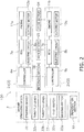
- FIG. 2 is a block diagram showing a configuration of the marine propulsion system 100.
- the marine propulsion system 100 includes a plurality of outboard motors 2 and a marine operating device 3.
- Each outboard motor 2 generates a thrust for propelling the watercraft 1.
- Each outboard motor 2 is an exemplary marine propulsion device.
- the outboard motor 2 attached to a port part of the stern of the watercraft 1 will be referred to as a first outboard motor 2a
- the outboard motor 2 attached to a starboard part of the stern of the watercraft 1 will be referred to as a second outboard motor 2b.
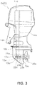
- FIG. 3 is a side view of the first outboard motor 2a.
- the first outboard motor 2a includes a propeller shaft 10a, an engine 11a, an electric motor 12a and a power transmission mechanism 13a.
- the second outboard motor 2b has a similar structure to the first outboard motor 2a.
- the propeller shaft 10a extends in the back-and-forth direction of the watercraft 1.
- a propeller 20a is attached to the propeller shaft 10a, while being unitarily rotated therewith.
- Each of the engine 11a and the electric motor 12a is a mechanical power source that generates the thrust for propelling the watercraft 1.
- the power transmission mechanism 13a transmits mechanical power to the propeller shaft 10a from at least one of the engine 11a and the electric motor 12a.
- the power transmission mechanism 13a includes a drive shaft 14a, an engine clutch 15a, a motor shaft 16a and a motor clutch 17a.
- the drive shaft 14a extends in the vertical direction.
- the drive shaft 14a is rotated when driven by the engine 11a.
- the engine clutch 15a connects or disconnects the drive shaft 14a and the propeller shaft 10a to or from each other. Besides, the engine clutch 15a switches between rotational directions of the propeller shaft 10a.
- the engine clutch 15a includes a drive gear 21a, a forward moving gear 22a, a rearward moving gear 23a and a dog clutch 24a.
- the drive gear 21a is rotated unitarily with the drive shaft 14a.
- the forward moving gear 22a and the rearward moving gear 23a are meshed with the drive gear 21a. Rotation of the drive shaft 14a is transmitted to the forward moving gear 22a and the rearward moving gear 23a through the drive gear 21a.
- the dog clutch 24a is movable to a forward moving position, a neutral position and a rearward moving position.
- the forward moving gear 22a is connected to the propeller shaft 10a, whereby rotation of the drive shaft 14a is transmitted to the propeller shaft 10a through the forward moving gear 22a.
- the dog clutch 24a is set in the neutral position, the propeller shaft 10a is disconnected from the forward moving gear 22a and the rearward moving gear 23a, whereby rotation of the drive shaft 14a is not transmitted to the propeller shaft 10a.
- the dog clutch 24a is set in the rearward moving position, the rearward moving gear 23a is connected to the propeller shaft 10a, whereby rotation of the drive shaft 14a is transmitted to the propeller shaft 10a through the rearward moving gear 23a.
- the motor shaft 16a extends in parallel to the drive shaft 14a.
- the motor shaft 16a is rotated when driven by the electric motor 12a.
- the motor clutch 17a connects or disconnects the motor shaft 16a and the propeller shaft 10a to or from each other.
- the motor clutch 17a is movable to a connecting position or a disconnecting position. When the motor clutch 17a is set in the connecting position, rotation of the motor shaft 16a is transmitted to the propeller shaft 10a through a motor gear (not shown in the drawings). When the motor clutch 17a is set in the disconnecting position, the propeller shaft 10a is disconnected from the motor gear, whereby rotation of the motor shaft 16a is not transmitted to the propeller shaft 10a.
- the first outboard motor 2a includes a controller 6a, an ECU (Electric Control Unit) 7a and an electric circuit 8a.
- the controller 6a controls the first outboard motor 2a.
- the controller 6a includes a processor such as a CPU (Central Processing Unit) and memories such as a RAM (Random Access Memory) and a ROM (Read Only Memory).
- the controller 6a stores programs and data for controlling the first outboard motor 2a.
- the controller 6a controls movement of the engine clutch 15a and that of the motor clutch 17a through actuators (not shown in the drawings) in accordance with an operating signal transmitted thereto from the marine operating device 3.
- the controller 6a controls driving and output of the engine 11a and/or those of the electric motor 12a in accordance with the operating signal transmitted thereto from the marine operating device 3. It should be noted that in the present preferred embodiment, the controller 6a controls the engine clutch 15a and the engine 11a through the ECU 7a.
- the controller 6a may be disposed inside the first outboard motor 2a, or alternatively, may be disposed outside the first outboard motor 2a.
- the ECU 7a controls the engine clutch 15a and the engine 11a based on a command issued by the controller 6a. For example, the ECU 7a controls the action of the engine clutch 15a and driving and output of the engine 11a in accordance with the command issued by the controller 6a.
- the ECU 7a includes a processor such as a CPU and memories such as a RAM and a ROM.
- the electric circuit 8a is a motor drive circuit and is connected to the electric motor 12a.
- the electric circuit 8a is an inverter, for instance, and converts direct voltage inputted thereto from a drive battery 26 (to be described) into alternating voltage and outputs the alternating voltage to the electric motor 12a.
- the electric circuit 8a includes a capacitor and a plurality of switching elements. The electric circuit 8a controls driving and output of the electric motor 12a in accordance with a command issued by the controller 6a.
- a main battery 25 and the drive battery 26 for driving the electric motor 12a are connected to the first outboard motor 2a.
- the main battery 25 and the drive battery 26 are exemplary batteries.
- the main battery 25 is a lead battery of 12V and supplies electric power to the first outboard motor 2a.
- the drive battery 26 is a lead battery of 36V and supplies electric power to the electric circuit 8a.
- the drive battery 26 is composed of, for instance, three lead batteries of 12V connected in series. It should be noted that in the present preferred embodiment, both the main battery 25 and the drive battery 26 are configured to be capable of supplying electric power to the electric circuit 8a.
- the first outboard motor 2a is provided with an electric power generator that generates electric power when driven by the engine 11a.
- the electric power generated by the electric power generator is supplied to the main battery 25 and the drive battery 26.
- the electric power generator includes, for instance, a rotor and a stator.
- the electric power generator generates electric power when the rotor connected to the drive shaft 14a is rotated with respect to the stator. It should be noted that the electric power, generated by the electric power generator, is supplied to the drive battery 26, for instance, after being rectified and controlled in voltage by a rectifier voltage regulator and further being increased in voltage to 36V by a DC/DC converter.
- the second outboard motor 2b similarly to the first outboard motor 2a, the second outboard motor 2b includes a controller 6b, an ECU 7b, an engine 11b, an electric circuit 8b and an electric motor 12b.
- the main battery 25 and the drive battery 26 are connected to the second outboard motor 2b. It should be noted that the configuration of the second outboard motor 2b is similar to that of the first outboard motor 2a, and hence, the detailed explanation thereof will be omitted.
- the controller 6a of the first outboard motor 2a and the controller 6b of the second outboard motor 2b are connected through wireless communication.
- the controllers 6a and 6b of the first and second outboard motors 2a and 2b are communicable to each other, while being each supplied with electric power from the main battery 25. It should be noted that the controllers 6a and 6b of the first and second outboard motors 2a and 2b may be connected through wired communication.
- the marine operating device 3 is disposed in a cockpit 30 set on the watercraft 1. As shown in FIG. 2 , the marine operating device 3 includes a steering device 31, throttle levers 32a and 32b, and a plurality of switches 33.
- the steering device 31 is a device for operating the turning direction of the watercraft 1.
- the throttle lever 32a is an operating member for regulating a thrust generated by the first outboard motor 2a and switching the direction of the thrust between forward and rearward directions.
- the throttle lever 32b is an operating member for regulating a thrust generated by the second outboard motor 2b and switching the direction of the thrust between forward and rearward directions.
- the plural switches 33 include a switch for starting each engine 11a, 11b, a switch for setting the vessel speed, and a switch for switching each outboard motor 2a, 2b among drive modes.
- the plural switches 33 include a first switch 33a and a second switch 33b.
- the first switch 33a connects or disconnects the main battery 25 and both the electric circuit 8a and the controller 6a to or from each other.
- the second switch 33b connects or disconnects the main battery 25 and both the electric circuit 8b and the controller 6b to or from each other.
- the first and second switches 33a and 33b are rotary switches.
- the first and second switches 33a and 33b may be disposed in remote positions from the cockpit 30.
- the first and second switches 33a and 33b are exemplary switches.
- first switch 33a When the first switch 33a is closed and turned to an on state, electric power is supplied to the first outboard motor 2a from the main battery 25 and the drive battery 26. When the first switch 33a is opened and turned to an off state, the main battery 25 and the drive battery 26 are blocked from being connected to the first outboard motor 2a. When the first switch 33a is in the off state, the controller 6a is not supplied with electric power, and hence, is incommunicable with the controller 6b of the second outboard motor 2b.
- the second switch 33b when the second switch 33b is closed and turned to an on state, electric power is supplied to the second outboard motor 2b from the main battery 25 and the drive battery 26.
- the second switch 33b When the second switch 33b is opened and turned to an off state, the main battery 25 and the drive battery 26 are blocked from being connected to the second outboard motor 2b.
- the controller 6b When the second switch 33b is in the off state, the controller 6b is not supplied with electric power, and hence, is incommunicable with the controller 6a of the first outboard motor 2a.
- FIG. 4 is a flowchart showing a series of control processing for limiting the output of the engine 11a to be executed by the controller 6a when the controller 6a is supplied with electric power. It should be noted that the controller 6b also executes a series of control processing similar to that executed by the controller 6a.
- step S101 the controller 6a determines whether or not the controller 6a is incommunicable with another controller (herein, the controller 6b).
- the controller 6a executes processing of step S102.
- step S102 the controller 6a limits the output of the engine 11a.
- the controller 6a limits the rotational speed of the propeller 20a by limiting the output of the engine 11a to prevent induced voltage, generated by entrained rotation of the electric motor 12b in the second outboard motor 2b, from exceeding a voltage proof (of, e.g., 63V) of the capacitor of the electric circuit 8b.
- the controller 6a limits the output of the engine 11a, for instance, to prevent the rotational speed of the propeller 20a from exceeding 1500 rpm.
- the controller 6a limits the output of the engine 11a, for instance, to prevent the rotational speed of the electric motor 12b due to the entrained rotation from exceeding 4000 rpm.
- step S103 the controller 6a informs a watercraft operator of that an output limited state of the engine 11a is being activated.
- the output limited state a limitation is put on the output of the engine 11a.
- the marine propulsion system 100 may herein further include an informing section 36.
- the controller 6a informs the watercraft operator of that the output limited state of the engine 11a is being activated by means of sound, light, indication displayed on a display device, or so forth through the informing section 36. Afterward, the controller 6a repeatedly executes the series of processing from step S101.
- the informing section 36 included in the marine propulsion system 100 enables the watercraft operator to easily notice that the output limited state of the engine 11a is being activated. In this case, when noticing that the second switch 33b is in the off state by checking the state of the second switch 33b, the watercraft operator can deactivate the output limited state of the engine 11a by turning the second switch 33b to the on state.
- step S101 when determining that the controller 6a is communicable with the controller 6b, the controller 6a executes processing of step S104.
- step S104 the controller 6a determines whether or not the output limited state of the engine 11a is being activated. When determining that the output limited state of the engine 11a is being activated, the controller 6a executes processing of step S105.
- step S105 the controller 6a cancels the limitation put on the output of the engine 11a.
- the controller 6a stops the informing section 36 from executing the informing processing.
- the controller 6a repeatedly executes the series of processing from step S101.
- step S104 When determining that the output limited state of the engine 11a is not being activated in step S104, the controller 6a repeatedly executes the series of processing from step S101.
- the marine propulsion system 100 may further include a deactivation section 37.
- the deactivation section 37 is an operating member such as a switch. When operated, the deactivation section 37 outputs a deactivation signal for deactivating the output limited state of the engine 11a, 11b to the controller 6a, 6b.
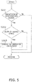
- FIG. 5 is a flowchart exemplifying a series of control processing for deactivating the output limited state of the engine 11a to be executed by the controller 6a. It should be noted that the controller 6b also executes a series of control processing similar to the series of control processing herein executed by the controller 6a.
- step S201 the controller 6a determines whether or not the controller 6a has received the deactivation signal from the deactivation section 37. When determining that the controller 6a has received the deactivation signal, the controller 6a executes processing of step S202.
- step S202 the controller 6a determines whether or not the output limited state of the engine 11a is being activated.
- the controller 6a executes processing of step S203.
- step S203 the controller 6a cancels the limitation put on the output of the engine 11a.
- the controller 6a stops the informing section 36 from executing the informing processing. It should be noted that the processing of deactivating the output limited state of the engine 11a is not executed when the controller 6a determines that the controller 6a has not received the deactivation signal in step S201 and when the controller 6a determines that the output limited state of the engine 11a is not being activated in step S202.
- the controller 6a puts a limitation on the output of the engine 11a, for instance, when being incommunicable with the controller 6b while being supplied with electric power from the main battery 25.
- the controller 6b puts a limitation on the output of the engine 11b when being incommunicable with the controller 6a while being supplied with electric power.
- a limitation is put on either the output of the engine 11a or that of the engine 11b. Accordingly, a limitation is put on the propulsion speed of the watercraft 1.
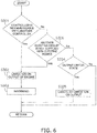
- FIG. 6 is a flowchart showing a series of control processing to be executed by the controller 6a according to a second preferred embodiment.
- the controller 6a limits the output of the engine 11a when being communicable with another controller (herein, the controller 6b) while another electric circuit (herein, the electric circuit 8b) is not supplied with electric power.
- the series of control processing to be executed by the controller 6a as shown in FIG. 6 is obtained by adding processing of step S306 to that in the first preferred embodiment, and is, except for this, similar to that in the first preferred embodiment. Therefore, the series of processing of steps S301 to S305 is similar to that of steps S101 to S105 shown in FIG. 4 , and explanation thereof will be hereinafter omitted.
- step S301 when determining that the controller 6a is communicable with the controller 6b, the controller 6a executes processing of step S306.
- step S306 the controller 6a obtains information regarding the electric circuit 8b from the controller 6b and determines whether or not the electric circuit 8b is not being supplied with electric power.
- the controller 6a puts a limitation on the output of the engine 11a (step S302).
- step S304 When determining that the electric circuit 8b is supplied with electric power, the controller 6a executes processing of step S304.
- FIG. 7 is a flowchart showing a series of control processing to be executed by the controller 6a according to a third preferred embodiment.
- the controller 6a limits the output of the engine 11a when another engine (herein, the engine 11b) is not being driven.
- the series of control processing to be executed by the controller 6a as shown in FIG. 7 is obtained by adding processing of step S406 to that in the first preferred embodiment and is, except for this, similar to that in the first preferred embodiment. Therefore, the series of processing of steps S401 to S405 is similar to that of steps S101 to S105 shown in FIG. 4 , and explanation thereof will be hereinafter omitted.
- step S401 when determining that the controller 6a is communicable with the controller 6b, the controller 6a executes processing of step S406.
- step S406 the controller 6a obtains information regarding the engine 11b from the controller 6b and determines whether or not the engine 11b is not being driven.
- step S406 when determining that the engine 11b is not being driven, the controller 6a puts a limitation on the output of the engine 11a (S402). It should be noted that, when it is determined that the controller 6a is incommunicable with the controller 6b in step S401, the engine 11b is in a substantially undriven state, whereby the controller 6a puts the limitation on the output of the engine 11a.
- the plural outboard motors 2 are composed of two outboard motors 2, i.e., the first and second outboard motors 2a and 2b.
- the plural outboard motors 2 may be composed of three or more outboard motors.
- the plural outboard motors 2 may further include another outboard motor 2 (hereinafter referred to as "third outboard motor") disposed between the first and second outboard motors 2a and 2b.
- the controller 6a puts a limitation on the output of the engine 11a when being incommunicable with either the controller 6b or a controller in the third outboard motor.
- the controller 6a cancels the limitation put on the output of the engine 11a when being communicable with both the controller 6b and the controller in the third outboard motor.
- each of the controller 6b and the controller in the third outboard motor also executes a series of processing similar to the series of processing executed by the controller 6a. For example, when the controllers 6a and 6b are communicable with each other but only the controller in the third outboard motor is incommunicable therewith, the controller 6a limits the output of the engine 11a while the controller 6b limits the output of the engine 11b.
- the controller 6a puts a limitation on the output of the engine 11a when the controller 6a is incommunicable with either the electric circuit 8b in the second outboard motor 2b or an electric circuit in the third outboard motor, or alternatively, when either the engine 11b in the second outboard motor 2b or an engine in the third outboard motor is not being driven.
- the controller 6a cancels the limitation put on the output of the engine 11a in transition from a condition that the controller 6a is incommunicable with either the electric circuit 8b in the second outboard motor 2b or the electric circuit in the third outboard motor to a condition that both the electric circuit 8b in the second outboard motor 2b and the electric circuit in the third outboard motor are being supplied with electric power.
- the controller 6a cancels the limitation put on the output of the engine 11a in transition from a condition that either the engine 11b in the second outboard motor 2b or the engine in the third outboard motor is not being driven to a condition that both the engine 11b in the second outboard motor 2b and the engine in the third outboard motor are being driven.
- the main battery 25 is provided for supplying electric power to the first and second outboard motors 2a and 2b.
- batteries may be provided in correspondence to the first and second outboard motors 2a and 2b, respectively.
- the drive battery 26 is not necessarily provided; the main battery 25 may also function as the drive battery 26.
- the power transmission mechanism 13a is configured to transmit mechanical power to the propeller shaft 10a from either one of the engine 11a and the electric motor 12a.
- the power transmission mechanism 13a may include a mechanism for transmitting both mechanical power of the engine 11a and that of the electric motor 12a.
- step S401 processing of step S401 may be omitted.
- the controllers 6a and 6b may not be configured to be communicable with each other.
- the controller 6a may determine that the engine 11b is not being driven based on an operating signal transmitted thereto from the marine operating device 3.
Landscapes
- Chemical & Material Sciences (AREA)
- Engineering & Computer Science (AREA)
- Combustion & Propulsion (AREA)
- Mechanical Engineering (AREA)
- Ocean & Marine Engineering (AREA)
- Control Of Vehicle Engines Or Engines For Specific Uses (AREA)
- Combined Controls Of Internal Combustion Engines (AREA)
- Control Of Electric Motors In General (AREA)
Abstract
Description
- The present invention relates to a marine propulsion system and a control method thereof.
- There has been conventionally known a type of marine propulsion system including both an engine and an electric motor as mechanical power sources for rotating a propeller shaft of a watercraft (see
JP 2017-218016 A - Besides, there has been known a type of watercraft including a plurality of marine propulsion devices as disclosed in
JP 2014-148273 A - For example, when three marine propulsion devices, each of which is of the type disclosed in
JP 2017-218016 A - It is an object of the present invention to provide a marine propulsion system and a method of controlling a marine propulsion system that can protect an electric circuit and an electric motor from induced voltage generated by entrained rotation of the electric motor in a marine propulsion system including a plurality of marine propulsion devices. According to the present invention said object is solved by a marine propulsion system having the features of independent claim 1. Moreover, said object of the present invention is also solved by a method of controlling a marine propulsion system having the features of independent claim 9. Preferred embodiments are laid down in the dependent claims.
- A marine propulsion system according to a first aspect of the present disclosure includes a plurality of marine propulsion devices. Each of the marine propulsion devices includes a propeller shaft, an engine, an electric motor, a power transmission mechanism transmitting mechanical power to the propeller shaft from at least one of the engine and the electric motor, an electric circuit connected to the electric motor, and a controller controlling the engine. The controllers in the plurality of marine propulsion devices are communicable with each other. When the controller in the each of the plurality of marine propulsion devices is set in a communicable state, the controller puts a limitation on an output of the engine in a condition that the controller is incommunicable with any of the others of the controllers in the plurality of marine propulsion devices.
- A marine propulsion system according to a second aspect of the present disclosure includes a plurality of marine propulsion devices. Each of the marine propulsion devices includes a propeller shaft, an engine, an electric motor, a power transmission mechanism transmitting mechanical power to the propeller shaft from at least one of the engine and the electric motor, an electric circuit connected to the electric motor, and a controller controlling the engine. In the each of the plurality of marine propulsion devices, the controller puts a limitation on an output of the engine when the engine is being driven while the engine in any of the others of the plurality of marine propulsion devices is not being driven.
- A control method according to a third aspect of the present disclosure relates to a method of controlling a marine propulsion system. The marine propulsion system includes a plurality of marine propulsion devices. Each of the plurality of marine propulsion devices includes a propeller shaft, an engine, an electric motor, a power transmission mechanism transmitting mechanical power to the propeller shaft from at least one of the engine and the electric motor, and an electric circuit connected to the electric motor. The method includes the following steps: determining whether or not the plurality of marine propulsion devices are communicable with each other; and putting a limitation on an output of the engine in each of the plurality of marine propulsion devices when the each of the plurality of marine propulsion devices is set in a communicable state in a condition that the each of the plurality of marine propulsion devices is incommunicable with any of the others of the plurality of marine propulsion devices.
- According to the marine propulsion system and the control method of the present disclosure, in each of the plurality of marine propulsion devices, when the controller is set in the communicable state, the controller puts a limitation on the output of the engine in the condition that the controller is incommunicable with any of the controllers in the others of the plurality of marine propulsion devices. In other words, the output of the engine is limited in each of the plurality of marine propulsion devices in the condition that any of the controllers in the others of the plurality of marine propulsion devices is not supplied with electric power. Accordingly, a watercraft is limited in propulsion speed. Hence, even when entrained rotation of the electric motor is caused while the controller is not supplied with electric power in any of the plurality of marine propulsion devices, increase in rotational speed of the electric motor can be inhibited. As a result, induced voltage generated by the electric motor can be inhibited. Hence, the electric circuit and the electric motor can be protected from the induced voltage generated by entrained rotation of the electric motor in any of the plurality of marine propulsion devices.
-
-
FIG. 1 is a perspective view of a watercraft including a marine propulsion system. -
FIG. 2 is a block diagram showing a configuration of the marine propulsion system. -
FIG. 3 is a side view of an outboard motor. -
FIG. 4 is a flowchart showing a series of control processing for limiting an output of an engine. -
FIG. 5 is a flowchart showing a series of control processing for deactivating an output limited state of the engine. -
FIG. 6 is a flowchart showing another series of control processing for limiting the output of the engine. -
FIG. 7 is a flowchart showing yet another series of control processing for limiting the output of the engine. - Preferred embodiments will be hereinafter explained with reference to drawings.
FIG. 1 is a perspective view of a watercraft 1 including amarine propulsion system 100 according to a first preferred embodiment.FIG. 2 is a block diagram showing a configuration of themarine propulsion system 100. Themarine propulsion system 100 includes a plurality ofoutboard motors 2 and amarine operating device 3. - Each
outboard motor 2 generates a thrust for propelling the watercraft 1. Eachoutboard motor 2 is an exemplary marine propulsion device. In the present preferred embodiment, theoutboard motor 2 attached to a port part of the stern of the watercraft 1 will be referred to as afirst outboard motor 2a, whereas theoutboard motor 2 attached to a starboard part of the stern of the watercraft 1 will be referred to as asecond outboard motor 2b. -
FIG. 3 is a side view of thefirst outboard motor 2a. Thefirst outboard motor 2a includes apropeller shaft 10a, anengine 11a, anelectric motor 12a and apower transmission mechanism 13a. It should be noted that thesecond outboard motor 2b has a similar structure to thefirst outboard motor 2a. - The
propeller shaft 10a extends in the back-and-forth direction of the watercraft 1. Apropeller 20a is attached to thepropeller shaft 10a, while being unitarily rotated therewith. Each of theengine 11a and theelectric motor 12a is a mechanical power source that generates the thrust for propelling the watercraft 1. - The
power transmission mechanism 13a transmits mechanical power to thepropeller shaft 10a from at least one of theengine 11a and theelectric motor 12a. Thepower transmission mechanism 13a includes adrive shaft 14a, anengine clutch 15a, amotor shaft 16a and amotor clutch 17a. - The
drive shaft 14a extends in the vertical direction. Thedrive shaft 14a is rotated when driven by theengine 11a. Theengine clutch 15a connects or disconnects thedrive shaft 14a and thepropeller shaft 10a to or from each other. Besides, theengine clutch 15a switches between rotational directions of thepropeller shaft 10a. - The
engine clutch 15a includes adrive gear 21a, a forward movinggear 22a, a rearward movinggear 23a and adog clutch 24a. Thedrive gear 21a is rotated unitarily with thedrive shaft 14a. The forward movinggear 22a and the rearward movinggear 23a are meshed with thedrive gear 21a. Rotation of thedrive shaft 14a is transmitted to the forward movinggear 22a and the rearward movinggear 23a through thedrive gear 21a. Thedog clutch 24a is movable to a forward moving position, a neutral position and a rearward moving position. - When the
dog clutch 24a is set in the forward moving position, the forward movinggear 22a is connected to thepropeller shaft 10a, whereby rotation of thedrive shaft 14a is transmitted to thepropeller shaft 10a through the forward movinggear 22a. When thedog clutch 24a is set in the neutral position, thepropeller shaft 10a is disconnected from the forward movinggear 22a and the rearward movinggear 23a, whereby rotation of thedrive shaft 14a is not transmitted to thepropeller shaft 10a. When thedog clutch 24a is set in the rearward moving position, the rearward movinggear 23a is connected to thepropeller shaft 10a, whereby rotation of thedrive shaft 14a is transmitted to thepropeller shaft 10a through the rearward movinggear 23a. - The
motor shaft 16a extends in parallel to thedrive shaft 14a. Themotor shaft 16a is rotated when driven by theelectric motor 12a. The motor clutch 17a connects or disconnects themotor shaft 16a and thepropeller shaft 10a to or from each other. The motor clutch 17a is movable to a connecting position or a disconnecting position. When the motor clutch 17a is set in the connecting position, rotation of themotor shaft 16a is transmitted to thepropeller shaft 10a through a motor gear (not shown in the drawings). When the motor clutch 17a is set in the disconnecting position, thepropeller shaft 10a is disconnected from the motor gear, whereby rotation of themotor shaft 16a is not transmitted to thepropeller shaft 10a. - As shown in
FIG. 2 , the firstoutboard motor 2a includes acontroller 6a, an ECU (Electric Control Unit) 7a and anelectric circuit 8a. Thecontroller 6a controls the firstoutboard motor 2a. Thecontroller 6a includes a processor such as a CPU (Central Processing Unit) and memories such as a RAM (Random Access Memory) and a ROM (Read Only Memory). Thecontroller 6a stores programs and data for controlling the firstoutboard motor 2a. - The
controller 6a controls movement of the engine clutch 15a and that of the motor clutch 17a through actuators (not shown in the drawings) in accordance with an operating signal transmitted thereto from themarine operating device 3. Thecontroller 6a controls driving and output of theengine 11a and/or those of theelectric motor 12a in accordance with the operating signal transmitted thereto from themarine operating device 3. It should be noted that in the present preferred embodiment, thecontroller 6a controls the engine clutch 15a and theengine 11a through theECU 7a. Thecontroller 6a may be disposed inside the firstoutboard motor 2a, or alternatively, may be disposed outside the firstoutboard motor 2a. - The
ECU 7a controls the engine clutch 15a and theengine 11a based on a command issued by thecontroller 6a. For example, theECU 7a controls the action of the engine clutch 15a and driving and output of theengine 11a in accordance with the command issued by thecontroller 6a. TheECU 7a includes a processor such as a CPU and memories such as a RAM and a ROM. - The
electric circuit 8a is a motor drive circuit and is connected to theelectric motor 12a. Theelectric circuit 8a is an inverter, for instance, and converts direct voltage inputted thereto from a drive battery 26 (to be described) into alternating voltage and outputs the alternating voltage to theelectric motor 12a. Theelectric circuit 8a includes a capacitor and a plurality of switching elements. Theelectric circuit 8a controls driving and output of theelectric motor 12a in accordance with a command issued by thecontroller 6a. - A
main battery 25 and thedrive battery 26 for driving theelectric motor 12a are connected to the firstoutboard motor 2a. Themain battery 25 and thedrive battery 26 are exemplary batteries. - For example, the
main battery 25 is a lead battery of 12V and supplies electric power to the firstoutboard motor 2a. Thedrive battery 26 is a lead battery of 36V and supplies electric power to theelectric circuit 8a. Thedrive battery 26 is composed of, for instance, three lead batteries of 12V connected in series. It should be noted that in the present preferred embodiment, both themain battery 25 and thedrive battery 26 are configured to be capable of supplying electric power to theelectric circuit 8a. - The first
outboard motor 2a is provided with an electric power generator that generates electric power when driven by theengine 11a. The electric power generated by the electric power generator is supplied to themain battery 25 and thedrive battery 26. The electric power generator includes, for instance, a rotor and a stator. The electric power generator generates electric power when the rotor connected to thedrive shaft 14a is rotated with respect to the stator. It should be noted that the electric power, generated by the electric power generator, is supplied to thedrive battery 26, for instance, after being rectified and controlled in voltage by a rectifier voltage regulator and further being increased in voltage to 36V by a DC/DC converter. - As shown in
FIG. 2 , similarly to the firstoutboard motor 2a, the secondoutboard motor 2b includes acontroller 6b, anECU 7b, anengine 11b, anelectric circuit 8b and anelectric motor 12b. Themain battery 25 and thedrive battery 26 are connected to the secondoutboard motor 2b. It should be noted that the configuration of the secondoutboard motor 2b is similar to that of the firstoutboard motor 2a, and hence, the detailed explanation thereof will be omitted. - The
controller 6a of the firstoutboard motor 2a and thecontroller 6b of the secondoutboard motor 2b are connected through wireless communication. Thecontrollers outboard motors main battery 25. It should be noted that thecontrollers outboard motors - The
marine operating device 3 is disposed in acockpit 30 set on the watercraft 1. As shown inFIG. 2 , themarine operating device 3 includes asteering device 31, throttle levers 32a and 32b, and a plurality ofswitches 33. Thesteering device 31 is a device for operating the turning direction of the watercraft 1. Thethrottle lever 32a is an operating member for regulating a thrust generated by the firstoutboard motor 2a and switching the direction of the thrust between forward and rearward directions. Thethrottle lever 32b is an operating member for regulating a thrust generated by the secondoutboard motor 2b and switching the direction of the thrust between forward and rearward directions. - The plural switches 33 include a switch for starting each
engine outboard motor first switch 33a and asecond switch 33b. Thefirst switch 33a connects or disconnects themain battery 25 and both theelectric circuit 8a and thecontroller 6a to or from each other. Thesecond switch 33b connects or disconnects themain battery 25 and both theelectric circuit 8b and thecontroller 6b to or from each other. For example, the first andsecond switches second switches cockpit 30. The first andsecond switches - When the
first switch 33a is closed and turned to an on state, electric power is supplied to the firstoutboard motor 2a from themain battery 25 and thedrive battery 26. When thefirst switch 33a is opened and turned to an off state, themain battery 25 and thedrive battery 26 are blocked from being connected to the firstoutboard motor 2a. When thefirst switch 33a is in the off state, thecontroller 6a is not supplied with electric power, and hence, is incommunicable with thecontroller 6b of the secondoutboard motor 2b. - Likewise, when the
second switch 33b is closed and turned to an on state, electric power is supplied to the secondoutboard motor 2b from themain battery 25 and thedrive battery 26. When thesecond switch 33b is opened and turned to an off state, themain battery 25 and thedrive battery 26 are blocked from being connected to the secondoutboard motor 2b. When thesecond switch 33b is in the off state, thecontroller 6b is not supplied with electric power, and hence, is incommunicable with thecontroller 6a of the firstoutboard motor 2a. - Next, a series of control processing to be executed by the
controller 6a will be explained with reference toFIG. 4. FIG. 4 is a flowchart showing a series of control processing for limiting the output of theengine 11a to be executed by thecontroller 6a when thecontroller 6a is supplied with electric power. It should be noted that thecontroller 6b also executes a series of control processing similar to that executed by thecontroller 6a. - In step S101, the
controller 6a determines whether or not thecontroller 6a is incommunicable with another controller (herein, thecontroller 6b). When determining that thecontroller 6a is incommunicable with thecontroller 6b, thecontroller 6a executes processing of step S102. In step S102, thecontroller 6a limits the output of theengine 11a. - Specifically, when being incommunicable with the
controller 6b, thecontroller 6a limits the rotational speed of thepropeller 20a by limiting the output of theengine 11a to prevent induced voltage, generated by entrained rotation of theelectric motor 12b in the secondoutboard motor 2b, from exceeding a voltage proof (of, e.g., 63V) of the capacitor of theelectric circuit 8b. Thecontroller 6a limits the output of theengine 11a, for instance, to prevent the rotational speed of thepropeller 20a from exceeding 1500 rpm. Alternatively, thecontroller 6a limits the output of theengine 11a, for instance, to prevent the rotational speed of theelectric motor 12b due to the entrained rotation from exceeding 4000 rpm. - In step S103, the
controller 6a informs a watercraft operator of that an output limited state of theengine 11a is being activated. In the output limited state, a limitation is put on the output of theengine 11a. As shown inFIG. 2 , themarine propulsion system 100 may herein further include an informingsection 36. Thecontroller 6a informs the watercraft operator of that the output limited state of theengine 11a is being activated by means of sound, light, indication displayed on a display device, or so forth through the informingsection 36. Afterward, thecontroller 6a repeatedly executes the series of processing from step S101. - The informing
section 36 included in themarine propulsion system 100 enables the watercraft operator to easily notice that the output limited state of theengine 11a is being activated. In this case, when noticing that thesecond switch 33b is in the off state by checking the state of thesecond switch 33b, the watercraft operator can deactivate the output limited state of theengine 11a by turning thesecond switch 33b to the on state. - In step S101, when determining that the
controller 6a is communicable with thecontroller 6b, thecontroller 6a executes processing of step S104. - In step S104, the
controller 6a determines whether or not the output limited state of theengine 11a is being activated. When determining that the output limited state of theengine 11a is being activated, thecontroller 6a executes processing of step S105. - In step S105, the
controller 6a cancels the limitation put on the output of theengine 11a. At this time, thecontroller 6a stops the informingsection 36 from executing the informing processing. Afterward, thecontroller 6a repeatedly executes the series of processing from step S101. - When determining that the output limited state of the
engine 11a is not being activated in step S104, thecontroller 6a repeatedly executes the series of processing from step S101. - As shown in
FIG. 2 , themarine propulsion system 100 may further include adeactivation section 37. For example, thedeactivation section 37 is an operating member such as a switch. When operated, thedeactivation section 37 outputs a deactivation signal for deactivating the output limited state of theengine controller -
FIG. 5 is a flowchart exemplifying a series of control processing for deactivating the output limited state of theengine 11a to be executed by thecontroller 6a. It should be noted that thecontroller 6b also executes a series of control processing similar to the series of control processing herein executed by thecontroller 6a. - In step S201, the
controller 6a determines whether or not thecontroller 6a has received the deactivation signal from thedeactivation section 37. When determining that thecontroller 6a has received the deactivation signal, thecontroller 6a executes processing of step S202. - In step S202, the
controller 6a determines whether or not the output limited state of theengine 11a is being activated. When determining that the output limited state of theengine 11a is being activated, thecontroller 6a executes processing of step S203. - In step S203, the
controller 6a cancels the limitation put on the output of theengine 11a. At this time, thecontroller 6a stops the informingsection 36 from executing the informing processing. It should be noted that the processing of deactivating the output limited state of theengine 11a is not executed when thecontroller 6a determines that thecontroller 6a has not received the deactivation signal in step S201 and when thecontroller 6a determines that the output limited state of theengine 11a is not being activated in step S202. - In the
marine propulsion system 100 described above, thecontroller 6a puts a limitation on the output of theengine 11a, for instance, when being incommunicable with thecontroller 6b while being supplied with electric power from themain battery 25. Alternatively, thecontroller 6b puts a limitation on the output of theengine 11b when being incommunicable with thecontroller 6a while being supplied with electric power. In other words, when either thecontroller 6a or thecontroller 6b is not supplied with electric power, a limitation is put on either the output of theengine 11a or that of theengine 11b. Accordingly, a limitation is put on the propulsion speed of the watercraft 1. Hence, when thecontroller 6b is not being supplied with electric power, for instance, increase in rotational speed of theelectric motor 12b due to the entrained rotation can be inhibited. As a result, theelectric circuit 8b and theelectric motor 12b can be protected from induced voltage generated by entrained rotation of theelectric motor 12b. - Incidentally, when the second
outboard motor 2b is tilted up, for instance, entrained rotation of theelectric motor 12b is not caused. Thus, even when thesecond switch 33b is kept in the off state, if themarine propulsion system 100 includes thedeactivation section 37, the output limited state of theengine 11a can be deactivated by operating thedeactivation section 37. -
FIG. 6 is a flowchart showing a series of control processing to be executed by thecontroller 6a according to a second preferred embodiment. In the second preferred embodiment, thecontroller 6a limits the output of theengine 11a when being communicable with another controller (herein, thecontroller 6b) while another electric circuit (herein, theelectric circuit 8b) is not supplied with electric power. It should be noted that the series of control processing to be executed by thecontroller 6a as shown inFIG. 6 is obtained by adding processing of step S306 to that in the first preferred embodiment, and is, except for this, similar to that in the first preferred embodiment. Therefore, the series of processing of steps S301 to S305 is similar to that of steps S101 to S105 shown inFIG. 4 , and explanation thereof will be hereinafter omitted. - In step S301, when determining that the
controller 6a is communicable with thecontroller 6b, thecontroller 6a executes processing of step S306. In step S306, thecontroller 6a obtains information regarding theelectric circuit 8b from thecontroller 6b and determines whether or not theelectric circuit 8b is not being supplied with electric power. When determining that theelectric circuit 8b is not being supplied with electric power, thecontroller 6a puts a limitation on the output of theengine 11a (step S302). When determining that theelectric circuit 8b is supplied with electric power, thecontroller 6a executes processing of step S304. -
FIG. 7 is a flowchart showing a series of control processing to be executed by thecontroller 6a according to a third preferred embodiment. In the third preferred embodiment, thecontroller 6a limits the output of theengine 11a when another engine (herein, theengine 11b) is not being driven. It should be noted that the series of control processing to be executed by thecontroller 6a as shown inFIG. 7 is obtained by adding processing of step S406 to that in the first preferred embodiment and is, except for this, similar to that in the first preferred embodiment. Therefore, the series of processing of steps S401 to S405 is similar to that of steps S101 to S105 shown inFIG. 4 , and explanation thereof will be hereinafter omitted. - In step S401, when determining that the
controller 6a is communicable with thecontroller 6b, thecontroller 6a executes processing of step S406. In step S406, thecontroller 6a obtains information regarding theengine 11b from thecontroller 6b and determines whether or not theengine 11b is not being driven. - In step S406, when determining that the
engine 11b is not being driven, thecontroller 6a puts a limitation on the output of theengine 11a (S402). It should be noted that, when it is determined that thecontroller 6a is incommunicable with thecontroller 6b in step S401, theengine 11b is in a substantially undriven state, whereby thecontroller 6a puts the limitation on the output of theengine 11a. - The preferred embodiments have been explained above. However, the present teaching is not limited to the preferred embodiments described above, and a variety of changes can be made. For example, the configuration of the
outboard motor 2 and/or that of themarine operating device 3 may be changed without being limited to those in the preferred embodiments described above. - In the preferred embodiments described above, the plural
outboard motors 2 are composed of twooutboard motors 2, i.e., the first and secondoutboard motors outboard motors 2 may be composed of three or more outboard motors. For example, the pluraloutboard motors 2 may further include another outboard motor 2 (hereinafter referred to as "third outboard motor") disposed between the first and secondoutboard motors controller 6a puts a limitation on the output of theengine 11a when being incommunicable with either thecontroller 6b or a controller in the third outboard motor. Besides, thecontroller 6a cancels the limitation put on the output of theengine 11a when being communicable with both thecontroller 6b and the controller in the third outboard motor. It should be noted that each of thecontroller 6b and the controller in the third outboard motor also executes a series of processing similar to the series of processing executed by thecontroller 6a. For example, when thecontrollers controller 6a limits the output of theengine 11a while thecontroller 6b limits the output of theengine 11b. - Similarly in the second and third preferred embodiments, the
controller 6a puts a limitation on the output of theengine 11a when thecontroller 6a is incommunicable with either theelectric circuit 8b in the secondoutboard motor 2b or an electric circuit in the third outboard motor, or alternatively, when either theengine 11b in the secondoutboard motor 2b or an engine in the third outboard motor is not being driven. Contrarily, thecontroller 6a cancels the limitation put on the output of theengine 11a in transition from a condition that thecontroller 6a is incommunicable with either theelectric circuit 8b in the secondoutboard motor 2b or the electric circuit in the third outboard motor to a condition that both theelectric circuit 8b in the secondoutboard motor 2b and the electric circuit in the third outboard motor are being supplied with electric power. Likewise, thecontroller 6a cancels the limitation put on the output of theengine 11a in transition from a condition that either theengine 11b in the secondoutboard motor 2b or the engine in the third outboard motor is not being driven to a condition that both theengine 11b in the secondoutboard motor 2b and the engine in the third outboard motor are being driven. - In the preferred embodiments described above, the
main battery 25 is provided for supplying electric power to the first and secondoutboard motors outboard motors drive battery 26 is not necessarily provided; themain battery 25 may also function as thedrive battery 26. - In the preferred embodiments described above, the
power transmission mechanism 13a is configured to transmit mechanical power to thepropeller shaft 10a from either one of theengine 11a and theelectric motor 12a. Alternatively, thepower transmission mechanism 13a may include a mechanism for transmitting both mechanical power of theengine 11a and that of theelectric motor 12a. - In the series of control processing to be executed by the
controller 6a according to the third preferred embodiment, processing of step S401 may be omitted. In this case, thecontrollers controller 6a may determine that theengine 11b is not being driven based on an operating signal transmitted thereto from themarine operating device 3.
Claims (15)
- A marine propulsion system (100) comprising:a plurality of marine propulsion devices (2, 2a, 2b), each of the marine propulsion devices (2, 2a, 2b) including a propeller shaft (10a), an engine (11a, 11b), an electric motor (12a, 12b), a power transmission mechanism (13a), an electric circuit (8a, 8b) and a controller (6a, 6b), the power transmission mechanism (13a) transmitting mechanical power to the propeller shaft (10a) from at least one of the engine (11a, 11b) and the electric motor (12a, 12b), the electric circuit (8a, 8b) connected to the electric motor (12a, 12b), the controller (6a, 6b) being configured to control the engine (11a, 11b), whereinin the each of the plurality of marine propulsion devices (2, 2a, 2b), the controller (6a, 6b) is configured to put a limitation on an output of the engine (11a, 11b) that is in a driving state when the engine (11a, 11b) in any other of the plurality of marine propulsion devices (2, 2a, 2b) is not being driven.
- A marine propulsion system (100) according to claim 1, wherein the controllers (6a, 6b) in the plurality of marine propulsion devices (2, 2a, 2b) are communicable with each other when in a communicable state, and
when the controller (6a, 6b) in the each of the plurality of marine propulsion devices (2, 2a, 2b) is in the communicable state, but one of the controllers (6a, 6b) is incommunicable with any other of the controllers (6a, 6b), the controller (6a, 6b) that is being supplied with electric power is configured to put the limitation on the output of the engine (11a, 11b) controlled by the controller (6a, 6b) that is being supplied with electric power. - The marine propulsion system (100) according to claim 2, wherein the controller (6a, 6b) that is being supplied with electric power is configured to cancel the limitation put on the output of the engine (11a, 11b) when the controller (6a, 6b) that is being supplied with electric power becomes communicable with the any other of the controllers (6a, 6b).
- The marine propulsion system (100) according to any one of claims 1 to 3, wherein in each of the plurality of marine propulsion devices (2, 2a, 2b), the controller (6a, 6b) is configured to put the limitation on the output of the engine (11a, 11b) such when the electric circuit (8a, 8b) in any other of the plurality of marine propulsion devices (2, 2a, 2b) is not being supplied with electric power.
- The marine propulsion system (100) according to claim 4, wherein in each of the plurality of marine propulsion devices (2, 2a, 2b), the controller (6a, 6b) is configured to cancel the limitation on the output of the engine (11a, 11b) when transitioning from the electric circuit (8a, 8b) in the any other of the plurality of marine propulsion devices (2, 2a, 2b) not being supplied with electric power to the electric circuits (8a, 8b) in all of the plurality of marine propulsion devices (2, 2a, 2b) being supplied with electric power.
- The marine propulsion system (100) according to any one of claims 1 to 5, wherein the each of the plurality of marine propulsion devices (2, 2a, 2b) further includes a battery (25, 26) configured to supply electric power to the electric circuit (8a, 8b) and the controller (6a, 6b), and
a switch (33) configured to connect or disconnect the battery (25, 26) and both the electric circuit (8a, 8b) and the controller (6a, 6b) to or from each other. - The marine propulsion system (100) according to any one of claims 1 to 6, further comprising:
an informing section (36) configured to inform a watercraft operator of that an output limited state is being activated by the controller (6a, 6b) to put the limitation on the output of the engine (11a, 11b). - The marine propulsion system (100) according to claim 7, further comprising:a deactivation section (37) configured to output a deactivation signal to the controller (6a, 6b) to deactivate the output limited state, whereinthe controller (6a, 6b) is configured to deactivate the output limited state in reception of the deactivation signal from the deactivation section (37).
- A method of controlling a marine propulsion system (100), the marine propulsion system (100) including a plurality of marine propulsion devices (2, 2a, 2b), each of the plurality of marine propulsion devices (2, 2a, 2b) including a propeller shaft (10a), an engine (11a, 11b), an electric motor (12a, 12b), a power transmission mechanism (13a) and an electric circuit (8a, 8b), the power transmission mechanism (13a) transmitting mechanical power to the propeller shaft (10a) from at least one of the engine (11a, 11b) and the electric motor (12a, 12b), the electric circuit (8a, 8b) connected to the electric motor (12a, 12b), the method comprising:
putting a limitation on an output of the engine (11a, 11b) that is in a driving state when the engine (11a, 11b) in any other of the plurality of marine propulsion devices (2, 2a, 2b) is not being driven. - The method according to claim 9, further comprising:determining whether or not the plurality of marine propulsion devices (2, 2a, 2b) are in a communicable state with each other; andputting the limitation on the output of the engine (11a, 11b) of the plurality of marine propulsion devices (2, 24, 2b) that is being supplied with electric power when one of the plurality of marine propulsion devices (2, 2a, 2b) is incommunicable with any other of the plurality of marine propulsion devices (2, 2a, 2b).
- The method according to claim 10, further comprising:
removing the limitation put on the output of the engine (11a, 11b) of the plurality of marine propulsion devices (2, 2a, 2b) that is being supplied with electric power when the one of the plurality of marine propulsion devices (2, 2a, 2b) that is incommunicable becomes communicable with all others of the plurality of marine propulsion devices (2, 2a, 2b). - The method according to any one of claims 9 to 11, further comprising:
putting the limitation on the output of the engine (11a, 11b) of the plurality of marine propulsion devices (2, 2a, 2b) when the electric circuit (8a, 8b) in any other of the plurality of marine propulsion devices (2, 2a, 2b) is not supplied with electric power. - The method according to claim 12, further comprising:
removing the limitation put on the output of the engine (11a, 11b) of the plurality of marine propulsion devices (2, 2a, 2b) in transition from a condition that the electric circuit (8a, 8b) in the any other of the plurality of marine propulsion devices (2, 2a, 2b) is not supplied with electric power to a condition that the electric circuits (8a, 8b) in all of the others of the plurality of marine propulsion devices (2, 2a, 2b) are supplied with electric power. - The method according to any one of claims 9 to 13, further comprising:
informing a watercraft operator of that an output limited state is being activated to impose the limitation on the output of the engine (11a, 11b). - The method according to claim 14, further comprising:outputting a deactivation signal to deactivate the output limited state; anddeactivating the output limited state in reception of the deactivation signal.
Applications Claiming Priority (1)
| Application Number | Priority Date | Filing Date | Title |
|---|---|---|---|
| JP2020036124A JP2021138229A (en) | 2020-03-03 | 2020-03-03 | Ship propulsion system and control method |
Publications (2)
| Publication Number | Publication Date |
|---|---|
| EP3875361A1 true EP3875361A1 (en) | 2021-09-08 |
| EP3875361B1 EP3875361B1 (en) | 2023-07-19 |
Family
ID=74673073
Family Applications (1)
| Application Number | Title | Priority Date | Filing Date |
|---|---|---|---|
| EP21158398.4A Active EP3875361B1 (en) | 2020-03-03 | 2021-02-22 | Marine propulsion system and control method |
Country Status (3)
| Country | Link |
|---|---|
| US (1) | US11866140B2 (en) |
| EP (1) | EP3875361B1 (en) |
| JP (1) | JP2021138229A (en) |
Families Citing this family (1)
| Publication number | Priority date | Publication date | Assignee | Title |
|---|---|---|---|---|
| US12612144B1 (en) * | 2023-06-14 | 2026-04-28 | Brunswick Corporation | Electric marine propulsion system and control method |
Citations (2)
| Publication number | Priority date | Publication date | Assignee | Title |
|---|---|---|---|---|
| JP2014148273A (en) | 2013-02-01 | 2014-08-21 | Honda Motor Co Ltd | Controller for ship |
| JP2017218016A (en) | 2016-06-07 | 2017-12-14 | ヤマハ発動機株式会社 | Ship propulsion machine |
-
2020
- 2020-03-03 JP JP2020036124A patent/JP2021138229A/en active Pending
-
2021
- 2021-02-22 EP EP21158398.4A patent/EP3875361B1/en active Active
- 2021-03-01 US US17/187,919 patent/US11866140B2/en active Active
Patent Citations (2)
| Publication number | Priority date | Publication date | Assignee | Title |
|---|---|---|---|---|
| JP2014148273A (en) | 2013-02-01 | 2014-08-21 | Honda Motor Co Ltd | Controller for ship |
| JP2017218016A (en) | 2016-06-07 | 2017-12-14 | ヤマハ発動機株式会社 | Ship propulsion machine |
Also Published As
| Publication number | Publication date |
|---|---|
| US11866140B2 (en) | 2024-01-09 |
| EP3875361B1 (en) | 2023-07-19 |
| JP2021138229A (en) | 2021-09-16 |
| US20210276686A1 (en) | 2021-09-09 |
Similar Documents
| Publication | Publication Date | Title |
|---|---|---|
| JP2016074250A (en) | Maneuvering system | |
| EP3892530B1 (en) | Marine propulsion system and control method | |
| JP4256418B2 (en) | Ship cruise control system | |
| EP4224897A1 (en) | System for and method of controlling watercraft | |
| US12528572B2 (en) | Watercraft propulsion system, and watercraft | |
| JP2021154946A (en) | Marine power supply system, and control method of marine power supply system | |
| US7886678B2 (en) | Watercraft | |
| EP3875361B1 (en) | Marine propulsion system and control method | |
| US20240092469A1 (en) | Marine propulsion system, vessel, and control method | |
| JP2022067892A (en) | Power source system for vessel and vessel | |
| EP3868645B1 (en) | Marine propulsion system and control method | |
| EP1770007B1 (en) | Boat | |
| US11312461B1 (en) | Boat maneuvering control system for boat and boat maneuvering control method for boat | |
| US11641123B2 (en) | Power supply system for watercraft | |
| EP3885249B1 (en) | Drive source switching system for marine propulsion device including multiple drive sources, and method of switching drive sources of marine propulsion device | |
| US20250042526A1 (en) | Watercraft propulsion system, and watercraft | |
| EP4253222B1 (en) | System for and method of controlling watercraft | |
| US11530676B2 (en) | Power supply system for watercraft | |
| JP2024101414A (en) | Ship steering system and ship equipped with same | |
| JP2024101415A (en) | Ship steering system and ship equipped with same | |
| JP2025050499A (en) | Ship control method, ship control program, ship control system and ship | |
| JP2024101413A (en) | Ship steering system and ship equipped with same |
Legal Events
| Date | Code | Title | Description |
|---|---|---|---|
| PUAI | Public reference made under article 153(3) epc to a published international application that has entered the european phase |
Free format text: ORIGINAL CODE: 0009012 |
|
| STAA | Information on the status of an ep patent application or granted ep patent |
Free format text: STATUS: THE APPLICATION HAS BEEN PUBLISHED |
|
| AK | Designated contracting states |
Kind code of ref document: A1 Designated state(s): AL AT BE BG CH CY CZ DE DK EE ES FI FR GB GR HR HU IE IS IT LI LT LU LV MC MK MT NL NO PL PT RO RS SE SI SK SM TR |
|
| STAA | Information on the status of an ep patent application or granted ep patent |
Free format text: STATUS: REQUEST FOR EXAMINATION WAS MADE |
|
| 17P | Request for examination filed |
Effective date: 20211130 |
|
| RBV | Designated contracting states (corrected) |
Designated state(s): AL AT BE BG CH CY CZ DE DK EE ES FI FR GB GR HR HU IE IS IT LI LT LU LV MC MK MT NL NO PL PT RO RS SE SI SK SM TR |
|
| GRAP | Despatch of communication of intention to grant a patent |
Free format text: ORIGINAL CODE: EPIDOSNIGR1 |
|
| STAA | Information on the status of an ep patent application or granted ep patent |
Free format text: STATUS: GRANT OF PATENT IS INTENDED |
|
| INTG | Intention to grant announced |
Effective date: 20230313 |
|
| GRAS | Grant fee paid |
Free format text: ORIGINAL CODE: EPIDOSNIGR3 |
|
| GRAA | (expected) grant |
Free format text: ORIGINAL CODE: 0009210 |
|
| STAA | Information on the status of an ep patent application or granted ep patent |
Free format text: STATUS: THE PATENT HAS BEEN GRANTED |
|
| P01 | Opt-out of the competence of the unified patent court (upc) registered |
Effective date: 20230601 |
|
| AK | Designated contracting states |
Kind code of ref document: B1 Designated state(s): AL AT BE BG CH CY CZ DE DK EE ES FI FR GB GR HR HU IE IS IT LI LT LU LV MC MK MT NL NO PL PT RO RS SE SI SK SM TR |
|
| REG | Reference to a national code |
Ref country code: GB Ref legal event code: FG4D |
|
| REG | Reference to a national code |
Ref country code: CH Ref legal event code: EP |
|
| REG | Reference to a national code |
Ref country code: DE Ref legal event code: R096 Ref document number: 602021003514 Country of ref document: DE |
|
| REG | Reference to a national code |
Ref country code: IE Ref legal event code: FG4D |
|
| REG | Reference to a national code |
Ref country code: NL Ref legal event code: FP |
|
| REG | Reference to a national code |
Ref country code: LT Ref legal event code: MG9D |
|
| REG | Reference to a national code |
Ref country code: AT Ref legal event code: MK05 Ref document number: 1589219 Country of ref document: AT Kind code of ref document: T Effective date: 20230719 |
|
| PG25 | Lapsed in a contracting state [announced via postgrant information from national office to epo] |
Ref country code: GR Free format text: LAPSE BECAUSE OF FAILURE TO SUBMIT A TRANSLATION OF THE DESCRIPTION OR TO PAY THE FEE WITHIN THE PRESCRIBED TIME-LIMIT Effective date: 20231020 |
|
| PG25 | Lapsed in a contracting state [announced via postgrant information from national office to epo] |
Ref country code: IS Free format text: LAPSE BECAUSE OF FAILURE TO SUBMIT A TRANSLATION OF THE DESCRIPTION OR TO PAY THE FEE WITHIN THE PRESCRIBED TIME-LIMIT Effective date: 20231119 |
|
| PG25 | Lapsed in a contracting state [announced via postgrant information from national office to epo] |
Ref country code: SE Free format text: LAPSE BECAUSE OF FAILURE TO SUBMIT A TRANSLATION OF THE DESCRIPTION OR TO PAY THE FEE WITHIN THE PRESCRIBED TIME-LIMIT Effective date: 20230719 Ref country code: RS Free format text: LAPSE BECAUSE OF FAILURE TO SUBMIT A TRANSLATION OF THE DESCRIPTION OR TO PAY THE FEE WITHIN THE PRESCRIBED TIME-LIMIT Effective date: 20230719 Ref country code: PT Free format text: LAPSE BECAUSE OF FAILURE TO SUBMIT A TRANSLATION OF THE DESCRIPTION OR TO PAY THE FEE WITHIN THE PRESCRIBED TIME-LIMIT Effective date: 20231120 Ref country code: NO Free format text: LAPSE BECAUSE OF FAILURE TO SUBMIT A TRANSLATION OF THE DESCRIPTION OR TO PAY THE FEE WITHIN THE PRESCRIBED TIME-LIMIT Effective date: 20231019 Ref country code: LV Free format text: LAPSE BECAUSE OF FAILURE TO SUBMIT A TRANSLATION OF THE DESCRIPTION OR TO PAY THE FEE WITHIN THE PRESCRIBED TIME-LIMIT Effective date: 20230719 Ref country code: LT Free format text: LAPSE BECAUSE OF FAILURE TO SUBMIT A TRANSLATION OF THE DESCRIPTION OR TO PAY THE FEE WITHIN THE PRESCRIBED TIME-LIMIT Effective date: 20230719 Ref country code: IS Free format text: LAPSE BECAUSE OF FAILURE TO SUBMIT A TRANSLATION OF THE DESCRIPTION OR TO PAY THE FEE WITHIN THE PRESCRIBED TIME-LIMIT Effective date: 20231119 Ref country code: HR Free format text: LAPSE BECAUSE OF FAILURE TO SUBMIT A TRANSLATION OF THE DESCRIPTION OR TO PAY THE FEE WITHIN THE PRESCRIBED TIME-LIMIT Effective date: 20230719 Ref country code: GR Free format text: LAPSE BECAUSE OF FAILURE TO SUBMIT A TRANSLATION OF THE DESCRIPTION OR TO PAY THE FEE WITHIN THE PRESCRIBED TIME-LIMIT Effective date: 20231020 Ref country code: FI Free format text: LAPSE BECAUSE OF FAILURE TO SUBMIT A TRANSLATION OF THE DESCRIPTION OR TO PAY THE FEE WITHIN THE PRESCRIBED TIME-LIMIT Effective date: 20230719 Ref country code: AT Free format text: LAPSE BECAUSE OF FAILURE TO SUBMIT A TRANSLATION OF THE DESCRIPTION OR TO PAY THE FEE WITHIN THE PRESCRIBED TIME-LIMIT Effective date: 20230719 |
|
| PG25 | Lapsed in a contracting state [announced via postgrant information from national office to epo] |
Ref country code: PL Free format text: LAPSE BECAUSE OF FAILURE TO SUBMIT A TRANSLATION OF THE DESCRIPTION OR TO PAY THE FEE WITHIN THE PRESCRIBED TIME-LIMIT Effective date: 20230719 |
|
| REG | Reference to a national code |
Ref country code: DE Ref legal event code: R097 Ref document number: 602021003514 Country of ref document: DE |
|
| PG25 | Lapsed in a contracting state [announced via postgrant information from national office to epo] |
Ref country code: ES Free format text: LAPSE BECAUSE OF FAILURE TO SUBMIT A TRANSLATION OF THE DESCRIPTION OR TO PAY THE FEE WITHIN THE PRESCRIBED TIME-LIMIT Effective date: 20230719 |
|
| PG25 | Lapsed in a contracting state [announced via postgrant information from national office to epo] |
Ref country code: SM Free format text: LAPSE BECAUSE OF FAILURE TO SUBMIT A TRANSLATION OF THE DESCRIPTION OR TO PAY THE FEE WITHIN THE PRESCRIBED TIME-LIMIT Effective date: 20230719 Ref country code: RO Free format text: LAPSE BECAUSE OF FAILURE TO SUBMIT A TRANSLATION OF THE DESCRIPTION OR TO PAY THE FEE WITHIN THE PRESCRIBED TIME-LIMIT Effective date: 20230719 Ref country code: ES Free format text: LAPSE BECAUSE OF FAILURE TO SUBMIT A TRANSLATION OF THE DESCRIPTION OR TO PAY THE FEE WITHIN THE PRESCRIBED TIME-LIMIT Effective date: 20230719 Ref country code: EE Free format text: LAPSE BECAUSE OF FAILURE TO SUBMIT A TRANSLATION OF THE DESCRIPTION OR TO PAY THE FEE WITHIN THE PRESCRIBED TIME-LIMIT Effective date: 20230719 Ref country code: DK Free format text: LAPSE BECAUSE OF FAILURE TO SUBMIT A TRANSLATION OF THE DESCRIPTION OR TO PAY THE FEE WITHIN THE PRESCRIBED TIME-LIMIT Effective date: 20230719 Ref country code: CZ Free format text: LAPSE BECAUSE OF FAILURE TO SUBMIT A TRANSLATION OF THE DESCRIPTION OR TO PAY THE FEE WITHIN THE PRESCRIBED TIME-LIMIT Effective date: 20230719 Ref country code: SK Free format text: LAPSE BECAUSE OF FAILURE TO SUBMIT A TRANSLATION OF THE DESCRIPTION OR TO PAY THE FEE WITHIN THE PRESCRIBED TIME-LIMIT Effective date: 20230719 |
|
| PLBE | No opposition filed within time limit |
Free format text: ORIGINAL CODE: 0009261 |
|
| STAA | Information on the status of an ep patent application or granted ep patent |
Free format text: STATUS: NO OPPOSITION FILED WITHIN TIME LIMIT |
|
| PG25 | Lapsed in a contracting state [announced via postgrant information from national office to epo] |
Ref country code: IT Free format text: LAPSE BECAUSE OF FAILURE TO SUBMIT A TRANSLATION OF THE DESCRIPTION OR TO PAY THE FEE WITHIN THE PRESCRIBED TIME-LIMIT Effective date: 20230719 |
|
| 26N | No opposition filed |
Effective date: 20240422 |
|
| PG25 | Lapsed in a contracting state [announced via postgrant information from national office to epo] |
Ref country code: SI Free format text: LAPSE BECAUSE OF FAILURE TO SUBMIT A TRANSLATION OF THE DESCRIPTION OR TO PAY THE FEE WITHIN THE PRESCRIBED TIME-LIMIT Effective date: 20230719 |
|
| PG25 | Lapsed in a contracting state [announced via postgrant information from national office to epo] |
Ref country code: MC Free format text: LAPSE BECAUSE OF FAILURE TO SUBMIT A TRANSLATION OF THE DESCRIPTION OR TO PAY THE FEE WITHIN THE PRESCRIBED TIME-LIMIT Effective date: 20230719 |
|
| REG | Reference to a national code |
Ref country code: CH Ref legal event code: PL |
|
| PG25 | Lapsed in a contracting state [announced via postgrant information from national office to epo] |
Ref country code: LU Free format text: LAPSE BECAUSE OF NON-PAYMENT OF DUE FEES Effective date: 20240222 |
|
| PG25 | Lapsed in a contracting state [announced via postgrant information from national office to epo] |
Ref country code: CH Free format text: LAPSE BECAUSE OF NON-PAYMENT OF DUE FEES Effective date: 20240229 |
|
| PG25 | Lapsed in a contracting state [announced via postgrant information from national office to epo] |
Ref country code: LU Free format text: LAPSE BECAUSE OF NON-PAYMENT OF DUE FEES Effective date: 20240222 Ref country code: CH Free format text: LAPSE BECAUSE OF NON-PAYMENT OF DUE FEES Effective date: 20240229 |
|
| PG25 | Lapsed in a contracting state [announced via postgrant information from national office to epo] |
Ref country code: BG Free format text: LAPSE BECAUSE OF FAILURE TO SUBMIT A TRANSLATION OF THE DESCRIPTION OR TO PAY THE FEE WITHIN THE PRESCRIBED TIME-LIMIT Effective date: 20230719 |
|
| PG25 | Lapsed in a contracting state [announced via postgrant information from national office to epo] |
Ref country code: BG Free format text: LAPSE BECAUSE OF FAILURE TO SUBMIT A TRANSLATION OF THE DESCRIPTION OR TO PAY THE FEE WITHIN THE PRESCRIBED TIME-LIMIT Effective date: 20230719 |
|
| REG | Reference to a national code |
Ref country code: BE Ref legal event code: MM Effective date: 20240229 |
|
| PG25 | Lapsed in a contracting state [announced via postgrant information from national office to epo] |
Ref country code: BE Free format text: LAPSE BECAUSE OF NON-PAYMENT OF DUE FEES Effective date: 20240229 |
|
| PG25 | Lapsed in a contracting state [announced via postgrant information from national office to epo] |
Ref country code: FR Free format text: LAPSE BECAUSE OF NON-PAYMENT OF DUE FEES Effective date: 20240229 |
|
| PG25 | Lapsed in a contracting state [announced via postgrant information from national office to epo] |
Ref country code: IE Free format text: LAPSE BECAUSE OF NON-PAYMENT OF DUE FEES Effective date: 20240222 |
|
| PG25 | Lapsed in a contracting state [announced via postgrant information from national office to epo] |
Ref country code: IE Free format text: LAPSE BECAUSE OF NON-PAYMENT OF DUE FEES Effective date: 20240222 Ref country code: FR Free format text: LAPSE BECAUSE OF NON-PAYMENT OF DUE FEES Effective date: 20240229 Ref country code: BE Free format text: LAPSE BECAUSE OF NON-PAYMENT OF DUE FEES Effective date: 20240229 |
|
| PG25 | Lapsed in a contracting state [announced via postgrant information from national office to epo] |
Ref country code: CY Free format text: LAPSE BECAUSE OF FAILURE TO SUBMIT A TRANSLATION OF THE DESCRIPTION OR TO PAY THE FEE WITHIN THE PRESCRIBED TIME-LIMIT; INVALID AB INITIO Effective date: 20210222 |
|
| PG25 | Lapsed in a contracting state [announced via postgrant information from national office to epo] |
Ref country code: HU Free format text: LAPSE BECAUSE OF FAILURE TO SUBMIT A TRANSLATION OF THE DESCRIPTION OR TO PAY THE FEE WITHIN THE PRESCRIBED TIME-LIMIT; INVALID AB INITIO Effective date: 20210222 |
|
| GBPC | Gb: european patent ceased through non-payment of renewal fee |
Effective date: 20250222 |
|
| PG25 | Lapsed in a contracting state [announced via postgrant information from national office to epo] |
Ref country code: TR Free format text: LAPSE BECAUSE OF FAILURE TO SUBMIT A TRANSLATION OF THE DESCRIPTION OR TO PAY THE FEE WITHIN THE PRESCRIBED TIME-LIMIT Effective date: 20230719 |
|
| PG25 | Lapsed in a contracting state [announced via postgrant information from national office to epo] |
Ref country code: GB Free format text: LAPSE BECAUSE OF NON-PAYMENT OF DUE FEES Effective date: 20250222 |
|
| PGFP | Annual fee paid to national office [announced via postgrant information from national office to epo] |
Ref country code: NL Payment date: 20260218 Year of fee payment: 6 |
|
| PGFP | Annual fee paid to national office [announced via postgrant information from national office to epo] |
Ref country code: DE Payment date: 20260218 Year of fee payment: 6 |