EP3875156A1 - Method and apparatus for autonomous buoy-based situational awareness for flying boats - Google Patents
Method and apparatus for autonomous buoy-based situational awareness for flying boats Download PDFInfo
- Publication number
- EP3875156A1 EP3875156A1 EP21160268.5A EP21160268A EP3875156A1 EP 3875156 A1 EP3875156 A1 EP 3875156A1 EP 21160268 A EP21160268 A EP 21160268A EP 3875156 A1 EP3875156 A1 EP 3875156A1
- Authority
- EP
- European Patent Office
- Prior art keywords
- autonomous
- water
- buoys
- autonomous buoys
- flying boat
- Prior art date
- Legal status (The legal status is an assumption and is not a legal conclusion. Google has not performed a legal analysis and makes no representation as to the accuracy of the status listed.)
- Granted
Links
Images

Classifications
-
- B—PERFORMING OPERATIONS; TRANSPORTING
- B63—SHIPS OR OTHER WATERBORNE VESSELS; RELATED EQUIPMENT
- B63G—OFFENSIVE OR DEFENSIVE ARRANGEMENTS ON VESSELS; MINE-LAYING; MINE-SWEEPING; SUBMARINES; AIRCRAFT CARRIERS
- B63G8/00—Underwater vessels, e.g. submarines; Equipment specially adapted therefor
- B63G8/001—Underwater vessels adapted for special purposes, e.g. unmanned underwater vessels; Equipment specially adapted therefor, e.g. docking stations
-
- B—PERFORMING OPERATIONS; TRANSPORTING
- B63—SHIPS OR OTHER WATERBORNE VESSELS; RELATED EQUIPMENT
- B63B—SHIPS OR OTHER WATERBORNE VESSELS; EQUIPMENT FOR SHIPPING
- B63B22/00—Buoys
- B63B22/003—Buoys adapted for being launched from an aircraft or water vehicle;, e.g. with brakes deployed in the water
-
- B—PERFORMING OPERATIONS; TRANSPORTING
- B64—AIRCRAFT; AVIATION; COSMONAUTICS
- B64C—AEROPLANES; HELICOPTERS
- B64C35/00—Flying-boats; Seaplanes
-
- B—PERFORMING OPERATIONS; TRANSPORTING
- B64—AIRCRAFT; AVIATION; COSMONAUTICS
- B64D—EQUIPMENT FOR FITTING IN OR TO AIRCRAFT; FLIGHT SUITS; PARACHUTES; ARRANGEMENT OR MOUNTING OF POWER PLANTS OR PROPULSION TRANSMISSIONS IN AIRCRAFT
- B64D1/00—Dropping, ejecting, releasing or receiving articles, liquids, or the like, in flight
- B64D1/02—Dropping, ejecting, or releasing articles
-
- B—PERFORMING OPERATIONS; TRANSPORTING
- B64—AIRCRAFT; AVIATION; COSMONAUTICS
- B64D—EQUIPMENT FOR FITTING IN OR TO AIRCRAFT; FLIGHT SUITS; PARACHUTES; ARRANGEMENT OR MOUNTING OF POWER PLANTS OR PROPULSION TRANSMISSIONS IN AIRCRAFT
- B64D1/00—Dropping, ejecting, releasing or receiving articles, liquids, or the like, in flight
- B64D1/22—Taking-up articles from earth's surface
-
- A—HUMAN NECESSITIES
- A62—LIFE-SAVING; FIRE-FIGHTING
- A62C—FIRE-FIGHTING
- A62C3/00—Fire prevention, containment or extinguishing specially adapted for particular objects or places
- A62C3/02—Fire prevention, containment or extinguishing specially adapted for particular objects or places for area conflagrations, e.g. forest fires, subterranean fires
- A62C3/0228—Fire prevention, containment or extinguishing specially adapted for particular objects or places for area conflagrations, e.g. forest fires, subterranean fires with delivery of fire extinguishing material by air or aircraft
- A62C3/0242—Fire prevention, containment or extinguishing specially adapted for particular objects or places for area conflagrations, e.g. forest fires, subterranean fires with delivery of fire extinguishing material by air or aircraft by spraying extinguishants from the aircraft
-
- B—PERFORMING OPERATIONS; TRANSPORTING
- B63—SHIPS OR OTHER WATERBORNE VESSELS; RELATED EQUIPMENT
- B63B—SHIPS OR OTHER WATERBORNE VESSELS; EQUIPMENT FOR SHIPPING
- B63B22/00—Buoys
- B63B2022/006—Buoys specially adapted for measuring or watch purposes
-
- B—PERFORMING OPERATIONS; TRANSPORTING
- B63—SHIPS OR OTHER WATERBORNE VESSELS; RELATED EQUIPMENT
- B63B—SHIPS OR OTHER WATERBORNE VESSELS; EQUIPMENT FOR SHIPPING
- B63B35/00—Vessels or similar floating structures specially adapted for specific purposes and not otherwise provided for
- B63B2035/006—Unmanned surface vessels, e.g. remotely controlled
- B63B2035/007—Unmanned surface vessels, e.g. remotely controlled autonomously operating
-
- B—PERFORMING OPERATIONS; TRANSPORTING
- B63—SHIPS OR OTHER WATERBORNE VESSELS; RELATED EQUIPMENT
- B63G—OFFENSIVE OR DEFENSIVE ARRANGEMENTS ON VESSELS; MINE-LAYING; MINE-SWEEPING; SUBMARINES; AIRCRAFT CARRIERS
- B63G8/00—Underwater vessels, e.g. submarines; Equipment specially adapted therefor
- B63G8/001—Underwater vessels adapted for special purposes, e.g. unmanned underwater vessels; Equipment specially adapted therefor, e.g. docking stations
- B63G2008/002—Underwater vessels adapted for special purposes, e.g. unmanned underwater vessels; Equipment specially adapted therefor, e.g. docking stations unmanned
- B63G2008/004—Underwater vessels adapted for special purposes, e.g. unmanned underwater vessels; Equipment specially adapted therefor, e.g. docking stations unmanned autonomously operating
-
- H—ELECTRICITY
- H04—ELECTRIC COMMUNICATION TECHNIQUE
- H04L—TRANSMISSION OF DIGITAL INFORMATION, e.g. TELEGRAPHIC COMMUNICATION
- H04L5/00—Arrangements affording multiple use of the transmission path
- H04L5/003—Arrangements for allocating sub-channels of the transmission path
- H04L5/0048—Allocation of pilot signals, i.e. of signals known to the receiver
Definitions
- Land-based firefighting has been supported by flying boat operations that enable transport of large quantities of water from offshore locations - e.g., oceans or lakes - to inland regions where the firefighting occurs.
- Water scooping from offshore environments may be challenging for flying boat operations for many reasons, including, for example, wave or current directions or the presence of structures that may move or otherwise reside temporarily on a water body surface (e.g., boats, particularly sailboats having upright masts) or that may permanently pierce the surface (e.g., piers or docks).
- These challenging environments for water scooping flying boats may be exacerbated by adverse weather conditions that cause low visibility.
- a method for establishing a situational awareness of a surface of a body of water includes deploying a plurality of autonomous buoys under or on the surface of the body of water; and scattering the plurality of autonomous buoys to form a mesh communication network.
- the method further includes establishing a communication link between the mesh communication network and a flying boat.
- the communication link is a radio frequency link.
- the plurality of autonomous buoys is configured to detect an obstacle floating on or beneath the surface of the body of water.
- each of the plurality of autonomous buoys includes an accelerometer configured to detect a wave motion.
- each of the plurality of autonomous buoys includes a first sensor configured to detect a current velocity and a current direction.
- each of the plurality of autonomous buoys includes a second sensor configured to detect a water depth or a range to an obstacle.
- the scattering of the plurality of autonomous buoys comprises activating a propulsor on each of the plurality of autonomous buoys.
- the method includes arranging the plurality of autonomous buoys into closely packed groups for retrieval.
- the arranging the plurality of autonomous buoys into closely packed groups for retrieval comprises activating the propulsor on each of the plurality of autonomous buoys.
- the method includes retrieving the plurality of autonomous buoys via a flying boat.
- an autonomous buoy configured for establishing a situational awareness of a surface of a body of water.
- the autonomous buoy includes a housing; a propulsor configured to propel the housing on or beneath the surface of the body of water; a first transceiver configured to transmit and receive data, to and from, respectively, a second autonomous buoy; and a second transceiver configured to send and receive data, to and from, respectively, a flying boat.
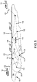
- a body of water 100 is illustrated having a plurality of autonomous buoys 102 scattered about a surface 104 of the body of water 100.
- An obstacle 106 such as, for example, a boat, is illustrated floating on the surface 104 of the body of water 100. While the obstacle 106 is illustrated as a boat, it shall be appreciated that the obstacle 106 may comprise any temporary or permanent structures or obstacles that float upon or pierce the surface 104 of the body of water 100, such as, for example, navigational markers, docks, piers, floating debris, flora, fauna or the like.
- the plurality of autonomous buoys 102 is illustrated in a scattered state, such that a mesh communication network 108 may be established among the individual autonomous buoys that comprise the plurality of autonomous buoys 102.
- the flying boat 124 then descends to the surface 104 of the body of water 100 to scoop the water. Following successful scooping of the water, the flying boat 124 ascends away from the surface 104 and transports the water to the point of interest, e.g., a location within a burning forest in the proximity of the body of water 100.
- the flying boat 124 may remain in contact with the mesh communication network 108 via the communication link 122 during the entire water scooping operation (e.g ., approach, touchdown, scoop, takeoff, go-around), which, in various embodiments, may stretch out for a significant distance (e.g ., one or two miles or more or several kilometers), enabling the pilot to abort the water scooping operation in the event an obstacle, such as, for example, a fast-moving boat, suddenly enters the path of the water scooping operation.
- a significant distance e.g ., one or two miles or more or several kilometers
- a suitable Human Machine Interface may be employed to guide a pilot of the flying boat 124 in carrying out the water scooping operation using the plurality of autonomous buoys 102, with the HMI configured to provide information concerning the obstacles, currents, wave dynamics and physical characteristics to the pilot.
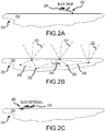
- the various autonomous buoys comprising the plurality of autonomous buoys 202 are scattered, autonomously, to various locations within the region in order to establish a mesh communication network 208, similar to the mesh communication network 108 described above with reference to FIG. 1 .
- a communication link 222 e.g., a radio frequency link
- the flying boat 224 when approaching the region in order to perform a water scooping operation (as described above with reference to FIG. 1 ), may be informed of an obstacle 206 (or a plurality of obstacles as the case may be) on or below the surface 204 of the body of water 200 within the region where the water scooping operation is to occur.
- the various autonomous buoys within the plurality of autonomous buoys 202 are grouped, autonomously, in a closely packed grouping (or a plurality of closely packed groupings) or a line of autonomous buoys (or a plurality of lies of autonomous buoys) that the flying boat 224 may approach and retrieve in one or more passes.
- the flying boat 224 may approach the closely packed grouping and scoop or otherwise retrieve the plurality of autonomous buoys 202.
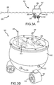
- the autonomous buoy 350 includes a propulsor 352.
- the propulsor 352 includes a propeller 354 configured to propel the autonomous buoy 350 through or over a body of water 300, typically upon a surface 304 of the body of water 300. While the propeller 354 is illustrated in FIGS. 3A and 3B , the disclosure contemplates any mechanism of propulsion, such as, for example, water paddles or wheels or water jets configured to propel the autonomous buoy 350.
- the autonomous buoy 350 may also include a power supply 366 configured to supply power to the various electrical components and to the propulsor 352.
- a processor 368 may also be included within the autonomous buoy 350 for processing the various signals received by various of the sensors and for communicating the resulting data among the members of the plurality of autonomous buoys and to the flying boat.
- the autonomous buoy 350 may also include a GPS receiver 370 configured to provide a precise location of the autonomous buoy 350.
- the GPS receiver 370 or the propulsor 352 may comprise a sensor configured to detect a current velocity or a current direction of the surface 304 of the body of water 300.
- the autonomous buoy 350 may also include an external sensor 372 (or a second sensor or a plurality of such sensors) configured to monitor the water conditions (e.g., temperature or salinity) surrounding the autonomous buoy 350. Further, in various embodiments, the autonomous buoy 350 may include an additional sensor 374 (e.g., a Depth (SONAR) or Ranging sensor (RADAR, LIDAR, IR)) configured to provide a precise depth or range of nearby obstacles around the autonomous buoy 350.
- an external sensor 372 or a second sensor or a plurality of such sensors
- the autonomous buoy 350 may include an additional sensor 374 (e.g., a Depth (SONAR) or Ranging sensor (RADAR, LIDAR, IR)) configured to provide a precise depth or range of nearby obstacles around the autonomous buoy 350.
- SONAR Depth
- RADAR Ranging sensor
- LIDAR LIDAR
- IR Ranging sensor
- a method 400 for performing a water scooping operation is described as having at least the following steps.
- a first step 402 a plurality of autonomous buoys is dropped or otherwise deployed on a surface of a water body.
- the plurality of autonomous buoys is scattered about a region and a mesh communication network is established.
- a water scooping operation is performed, where a flying boat communicates with the mesh communication network for information concerning obstacles, current conditions or wave motion.
- the plurality of autonomous buoys is arranged into one or more closely packed groups or lines for retrieval.
- a fifth step 410 the plurality of autonomous buoys is scooped or otherwise retrieved by the flying boat or another vessel.
- one or more of the foregoing method steps may also be employed as a method for establishing a situational awareness of a surface of a body of water, particularly for use in performing a water scooping operation.
- the disclosure provides a system for establishing a situational awareness while performing a water scooping operation.
- Data obtained by a plurality of autonomous buoys is received by a flying boat, processed by electronics and displayed, for example, on a screen within the flying boat.
- a pilot of the flying boat may then use the visual information on the screen to guide the flying boat to the surface of the water, perform the water scooping operation, and then exit the area as required to carry out a mission.
- the disclosed systems and apparatus provide, among other things, safety against water-based collisions with obstacles, such as, for example, boats, docks or piers and the like, even under dynamic circumstances where the obstacles are moving.
- Such systems and apparatus serve not only to increase safety, but to reduce pilot work load, especially when maneuvering in narrow or shallow channels or uncharted waterways.
- Numbers, percentages, or other values stated herein are intended to include that value, and also other values that are about or approximately equal to the stated value, as would be appreciated by one of ordinary skill in the art encompassed by various embodiments of the present disclosure.
- a stated value should therefore be interpreted broadly enough to encompass values that are at least close enough to the stated value to perform a desired function or achieve a desired result.
- the stated values include at least the variation to be expected in a suitable industrial process, and may include values that are within 10%, within 5%, within 1%, within 0.1%, or within 0.01% of a stated value.
- the terms “substantially,” “about” or “approximately” as used herein represent an amount close to the stated amount that still performs a desired function or achieves a desired result.
- the term “substantially,” “about” or “approximately” may refer to an amount that is within 10% of, within 5% of, within 1% of, within 0.1% of, and within 0.01% of a stated amount or value
- system program instructions or controller instructions may be loaded onto a tangible, non-transitory, computer-readable medium (also referred to herein as a tangible, non-transitory, memory) having instructions stored thereon that, in response to execution by a controller, cause the controller to perform various operations.
- a tangible, non-transitory, computer-readable medium also referred to herein as a tangible, non-transitory, memory
- non-transitory is to be understood to remove only propagating transitory signals per se from the claim scope and does not relinquish rights to all standard computer-readable media that are not only propagating transitory signals per se.
Landscapes
- Engineering & Computer Science (AREA)
- Aviation & Aerospace Engineering (AREA)
- Mechanical Engineering (AREA)
- Chemical & Material Sciences (AREA)
- Combustion & Propulsion (AREA)
- Ocean & Marine Engineering (AREA)
- Testing Or Calibration Of Command Recording Devices (AREA)
Abstract
Description
- This application claims priority to, and the benefit of, Indian Patent Application No.
202011009552 - The present disclosure relates generally to methods and apparatus for situational awareness and, more particularly, to methods and apparatus configured to provide flying boats with real-time awareness of conditions or structures on or piercing a water surface using autonomous buoys and sensors mounted thereon.
- Land-based firefighting has been supported by flying boat operations that enable transport of large quantities of water from offshore locations - e.g., oceans or lakes - to inland regions where the firefighting occurs. Water scooping from offshore environments may be challenging for flying boat operations for many reasons, including, for example, wave or current directions or the presence of structures that may move or otherwise reside temporarily on a water body surface (e.g., boats, particularly sailboats having upright masts) or that may permanently pierce the surface (e.g., piers or docks). These challenging environments for water scooping flying boats may be exacerbated by adverse weather conditions that cause low visibility. In such situations, pilots are generally guided based on prior information gathered about the water body, the prevailing weather conditions or visual cues observable by the pilot. Accordingly, existing solutions do not typically provide comprehensive real-time situational awareness to a pilot regarding the positions of temporary or permanent fixtures that reside on or pierce the surface of a water body, particularly where the water body is generally not accessed by flying boats, excepting for the need to access water on emergency bases, and the prevailing weather conditions interfere with visual observation of the water scooping conditions.
- A method for establishing a situational awareness of a surface of a body of water is disclosed. In various embodiments, the method includes deploying a plurality of autonomous buoys under or on the surface of the body of water; and scattering the plurality of autonomous buoys to form a mesh communication network. In various embodiments, the method further includes establishing a communication link between the mesh communication network and a flying boat. In various embodiments, the communication link is a radio frequency link.
- In various embodiments, the plurality of autonomous buoys is configured to detect an obstacle floating on or beneath the surface of the body of water. In various embodiments, each of the plurality of autonomous buoys includes an accelerometer configured to detect a wave motion. In various embodiments, each of the plurality of autonomous buoys includes a first sensor configured to detect a current velocity and a current direction. In various embodiments, each of the plurality of autonomous buoys includes a second sensor configured to detect a water depth or a range to an obstacle.
- In various embodiments, the situational awareness is employed by a flying boat during a water scooping operation. In various embodiments, the method further includes establishing a communication link between the mesh communication network and the flying boat prior to approach of the flying boat toward the plurality of autonomous buoys. In various embodiments, the method includes performing the water scooping operation after establishing the communication link. In various embodiments, the method includes maintaining the communication link during the water scooping operation.
- In various embodiments, the scattering of the plurality of autonomous buoys comprises activating a propulsor on each of the plurality of autonomous buoys. In various embodiments, the method includes arranging the plurality of autonomous buoys into closely packed groups for retrieval. In various embodiments, the arranging the plurality of autonomous buoys into closely packed groups for retrieval comprises activating the propulsor on each of the plurality of autonomous buoys. In various embodiments, the method includes retrieving the plurality of autonomous buoys via a flying boat.
- An autonomous buoy configured for establishing a situational awareness of a surface of a body of water is disclosed. In various embodiments, the autonomous buoy includes a housing; a propulsor configured to propel the housing on or beneath the surface of the body of water; a first transceiver configured to transmit and receive data, to and from, respectively, a second autonomous buoy; and a second transceiver configured to send and receive data, to and from, respectively, a flying boat.
- In various embodiments, an accelerometer is configured to detect a wave motion. In various embodiments, a first sensor is configured to detect a current velocity and a current direction. In various embodiments, a second sensor is configured to detect a water depth or a range to an obstacle.
- A method for performing a water scooping operation from a surface of a body of water is disclosed. In various embodiments, the method includes deploying a plurality of autonomous buoys under or on the surface of the body of water; scattering the plurality of autonomous buoys to form a mesh communication network; establishing a communication link between the mesh communication network and a flying boat; directing the flying boat to perform the water scooping operation; arranging the plurality of autonomous buoys into one or more closely packed groups for retrieval; and retrieving the plurality of autonomous buoys.
- The forgoing features and elements may be combined in any combination, without exclusivity, unless expressly indicated herein otherwise. These features and elements as well as the operation of the disclosed embodiments will become more apparent in light of the following description and accompanying drawings.
- The accompanying drawings illustrate various embodiments employing the principles described herein and are a part of the specification. The illustrated embodiments are meant for description and not to limit the scope of the claims.
-
FIG. 1 illustrates a perspective view of a flying boat approaching and exiting a water scooping zone on a water body surface populated with a plurality of autonomous buoys, in accordance with various embodiments; -
FIGS. 2A, 2B and 2C illustrate various views of a deployment, scattering and retrieval of a plurality of autonomous buoys, in accordance with various embodiments; -
FIG. 3A illustrates an autonomous buoy on the surface of a water body, in accordance with various embodiments; -
FIG. 3B illustrates a closeup schematic view of an autonomous buoy, in accordance with various embodiments; and -
FIG. 4 describes various method steps involved in deployment, scattering and retrieval of a plurality of autonomous buoys, in accordance with various embodiments. - The following detailed description of various embodiments herein makes reference to the accompanying drawings, which show various embodiments by way of illustration. While these various embodiments are described in sufficient detail to enable those skilled in the art to practice the disclosure, it should be understood that other embodiments may be realized and that changes may be made without departing from the scope of the disclosure as defined by the claims. Thus, the detailed description herein is presented for purposes of illustration only and not of limitation. Furthermore, any reference to singular includes plural embodiments, and any reference to more than one component or step may include a singular embodiment or step. Also, any reference to attached, fixed, connected, or the like may include permanent, removable, temporary, partial, full or any other possible attachment option. Additionally, any reference to without contact (or similar phrases) may also include reduced contact or minimal contact. It should also be understood that unless specifically stated otherwise, references to "a," "an" or "the" may include one or more than one and that reference to an item in the singular may also include the item in the plural. Further, all ranges may include upper and lower values and all ranges and ratio limits disclosed herein may be combined.
- Referring to
FIG. 1 , a body ofwater 100 is illustrated having a plurality ofautonomous buoys 102 scattered about asurface 104 of the body ofwater 100. Anobstacle 106, such as, for example, a boat, is illustrated floating on thesurface 104 of the body ofwater 100. While theobstacle 106 is illustrated as a boat, it shall be appreciated that theobstacle 106 may comprise any temporary or permanent structures or obstacles that float upon or pierce thesurface 104 of the body ofwater 100, such as, for example, navigational markers, docks, piers, floating debris, flora, fauna or the like. As will be described further below, the plurality ofautonomous buoys 102 is illustrated in a scattered state, such that amesh communication network 108 may be established among the individual autonomous buoys that comprise the plurality ofautonomous buoys 102. - In various embodiments, for example, a first
autonomous buoy 110, a secondautonomous buoy 112 and a thirdautonomous buoy 114 may be deployed in a region. Various sensors on each of the firstautonomous buoy 110, the secondautonomous buoy 112 and the thirdautonomous buoy 114 are configured, respectively, to detect obstacles floating on or underneath the surface of water within afirst network range 116, asecond network range 118 and athird network range 120. With the plurality ofautonomous buoys 102 comprising sufficient numbers and packed with sufficient density, the resultingmesh communication network 108 is able to detect obstacles floating on or underneath the surface of water within thesurface 104 of the body ofwater 100 of interest. As will be further described below, the various autonomous buoys comprising the plurality ofautonomous buoys 102 are configured not only to detect obstacles, but also to detect a current direction and a current velocity, wave dynamics, such as, for example, a wave direction and a wave height, and physical characteristics of the water, such as, for example, a water temperature and a water salinity. - In various embodiments, information concerning each of the above described parameters, including obstacles, currents, wave dynamics and physical characteristics, may be compiled within the
mesh communication network 108 and relayed via a communication link 122 (e.g., a radio frequency link) to aflying boat 124 approaching thesurface 104 of the body ofwater 100 for a water scooping operation. For example, as illustrated inFIG. 1 , the flyingboat 124 is first shown approaching thesurface 104, at which point radio frequency communication with themesh communication network 108 is established. Information concerning obstacles, current direction and wave dynamics is then communicated to the flying boat over thecommunication link 122. Assuming the pilot determines a water scooping operation may be safely attempted, the flyingboat 124 then descends to thesurface 104 of the body ofwater 100 to scoop the water. Following successful scooping of the water, the flyingboat 124 ascends away from thesurface 104 and transports the water to the point of interest, e.g., a location within a burning forest in the proximity of the body ofwater 100. Advantageously, and as illustrated, the flyingboat 124 may remain in contact with themesh communication network 108 via thecommunication link 122 during the entire water scooping operation (e.g., approach, touchdown, scoop, takeoff, go-around), which, in various embodiments, may stretch out for a significant distance (e.g., one or two miles or more or several kilometers), enabling the pilot to abort the water scooping operation in the event an obstacle, such as, for example, a fast-moving boat, suddenly enters the path of the water scooping operation. A suitable Human Machine Interface (HMI) may be employed to guide a pilot of the flyingboat 124 in carrying out the water scooping operation using the plurality ofautonomous buoys 102, with the HMI configured to provide information concerning the obstacles, currents, wave dynamics and physical characteristics to the pilot. - Referring now to
FIGS. 2A, 2B and 2C , a sequence of steps involved with the deployment, scattering and retrieval of a plurality ofautonomous buoys 202, similar to the plurality ofautonomous buoys 102 described above with reference toFIG. 1 , is illustrated. Referring toFIG. 2A , in a first step, a flyingboat 224 approaches a body ofwater 200 having asurface 204 within a region where water is to be scooped during a scooping operation. In various embodiments, the flyingboat 224 descends close to thesurface 204 and drops or otherwise deploys the plurality ofautonomous buoys 202 onto thesurface 204 of the body ofwater 200. Referring toFIG. 2B , in a second step, the various autonomous buoys comprising the plurality ofautonomous buoys 202 are scattered, autonomously, to various locations within the region in order to establish amesh communication network 208, similar to themesh communication network 108 described above with reference toFIG. 1 . Once scattered and themesh communication network 208 is established, a communication link 222 (e.g., a radio frequency link) is established such that the flyingboat 224, when approaching the region in order to perform a water scooping operation (as described above with reference toFIG. 1 ), may be informed of an obstacle 206 (or a plurality of obstacles as the case may be) on or below thesurface 204 of the body ofwater 200 within the region where the water scooping operation is to occur. Referring now toFIG. 2C , following completion of the firefighting operation, the various autonomous buoys within the plurality ofautonomous buoys 202 are grouped, autonomously, in a closely packed grouping (or a plurality of closely packed groupings) or a line of autonomous buoys (or a plurality of lies of autonomous buoys) that the flyingboat 224 may approach and retrieve in one or more passes. The flyingboat 224 may approach the closely packed grouping and scoop or otherwise retrieve the plurality ofautonomous buoys 202. In various embodiments, however, other manners of retrieving the plurality ofautonomous buoys 202 may be employed, such as, for example, landing the flyingboat 224 on thesurface 204 of the body ofwater 200 or directing a boat or surface ship to the region and collecting individual ones of the plurality ofautonomous buoys 202 by hand. - Referring now to
FIGS. 3A and 3B , various details of anautonomous buoy 350, similar to any of the plurality ofautonomous buoys 102 or the plurality ofautonomous buoys 202 described above with reference toFIGS. 1 and2A-2C , are illustrated, in accordance with various embodiments. Theautonomous buoy 350 includes apropulsor 352. In various embodiments, thepropulsor 352 includes apropeller 354 configured to propel theautonomous buoy 350 through or over a body ofwater 300, typically upon asurface 304 of the body ofwater 300. While thepropeller 354 is illustrated inFIGS. 3A and 3B , the disclosure contemplates any mechanism of propulsion, such as, for example, water paddles or wheels or water jets configured to propel theautonomous buoy 350. In various embodiments, theautonomous buoy 350 includes afirst transceiver 356 configured to transmit and receive data, to and from, respectively, each autonomous buoy within a plurality of autonomous buoys. For example, information concerning the precise location of theautonomous buoy 350 within a plurality of autonomous buoys facilitates maintaining of a mesh communication network, such as themesh communication network 108 described above with reference toFIG. 1 , by enabling the autonomous buoy 350 (together with its neighboring buoys) to maintain a precise location (or mesh configuration), notwithstanding currents or wave motion tending to move theautonomous buoy 350. Asecond transceiver 357 may be configured to send and receive data, to and from, respectively, a flying boat (e.g., the flyingboat 124 described above with reference toFIG. 1 ) during a water scooping operation. Thesecond transceiver 357 may also be used to send and receive data instructing theautonomous buoy 350 to move to a different location, such as, for example, during a retrieval process of a plurality of autonomous buoys. Thesecond transceiver 357 may also be configured to send and receive data with other aircraft or vessels in the vicinity that are not the ones that either deployed or will ultimately retrieve theautonomous buoy 350. - In various embodiments, the
autonomous buoy 350 further includesvarious sensors 358 or other electrical, navigational or communication-basedcomponents 360 that may be contained within ahousing 362, where thehousing 362 may also act as a hull or a water-tight enclosure for theautonomous buoy 350. Referring toFIG. 3B , for example, in various embodiments, theautonomous buoy 350 includes anaccelerometer 364. Theaccelerometer 364 may be configured to detect motion of theautonomous buoy 350 from a reference point. For example, the accelerometer may detect vertical or horizontal movement of theautonomous buoy 350 due to the action of wave motion. In various embodiments, theaccelerometer 364 may comprise a first sensor configured to detect a current velocity or a current direction of the surface of the body ofwater 300. Information about wave motion may, in certain circumstances, prove important to the pilot in determining the most effective line of approach for water scooping operation to occur. Theautonomous buoy 350 may also include apower supply 366 configured to supply power to the various electrical components and to thepropulsor 352. Aprocessor 368 may also be included within theautonomous buoy 350 for processing the various signals received by various of the sensors and for communicating the resulting data among the members of the plurality of autonomous buoys and to the flying boat. In various embodiments, theautonomous buoy 350 may also include aGPS receiver 370 configured to provide a precise location of theautonomous buoy 350. In various embodiments, theGPS receiver 370 or thepropulsor 352 may comprise a sensor configured to detect a current velocity or a current direction of thesurface 304 of the body ofwater 300. In various embodiments, theautonomous buoy 350 may also include an external sensor 372 (or a second sensor or a plurality of such sensors) configured to monitor the water conditions (e.g., temperature or salinity) surrounding theautonomous buoy 350. Further, in various embodiments, theautonomous buoy 350 may include an additional sensor 374 (e.g., a Depth (SONAR) or Ranging sensor (RADAR, LIDAR, IR)) configured to provide a precise depth or range of nearby obstacles around theautonomous buoy 350. - Referring now to
FIG. 4 , amethod 400 for performing a water scooping operation is described as having at least the following steps. In afirst step 402, a plurality of autonomous buoys is dropped or otherwise deployed on a surface of a water body. In asecond step 404, the plurality of autonomous buoys is scattered about a region and a mesh communication network is established. In athird step 406, a water scooping operation is performed, where a flying boat communicates with the mesh communication network for information concerning obstacles, current conditions or wave motion. In afourth step 408, following termination of a firefighting operation, the plurality of autonomous buoys is arranged into one or more closely packed groups or lines for retrieval. In afifth step 410, the plurality of autonomous buoys is scooped or otherwise retrieved by the flying boat or another vessel. In various embodiments, one or more of the foregoing method steps may also be employed as a method for establishing a situational awareness of a surface of a body of water, particularly for use in performing a water scooping operation. - The disclosure provides a system for establishing a situational awareness while performing a water scooping operation. Data obtained by a plurality of autonomous buoys is received by a flying boat, processed by electronics and displayed, for example, on a screen within the flying boat. A pilot of the flying boat may then use the visual information on the screen to guide the flying boat to the surface of the water, perform the water scooping operation, and then exit the area as required to carry out a mission. The disclosed systems and apparatus provide, among other things, safety against water-based collisions with obstacles, such as, for example, boats, docks or piers and the like, even under dynamic circumstances where the obstacles are moving. Such systems and apparatus serve not only to increase safety, but to reduce pilot work load, especially when maneuvering in narrow or shallow channels or uncharted waterways. Other benefits include a reduction in cost or time associated with advance scouting or data gathering of unknown or uncharted waterways and the ability to use waterways that are closer to areas requiring water transport (e.g., areas of forest fires), thereby saving fuel costs and reducing the time required for water transport.
- Benefits, other advantages, and solutions to problems have been described herein with regard to specific embodiments. Furthermore, the connecting lines shown in the various figures contained herein are intended to represent exemplary functional relationships and/or physical couplings between the various elements. It should be noted that many alternative or additional functional relationships or physical connections may be present in a practical system. However, the benefits, advantages, solutions to problems, and any elements that may cause any benefit, advantage, or solution to occur or become more pronounced are not to be construed as critical, required, or essential features or elements of the disclosure. The scope of the disclosure is accordingly to be limited by nothing other than the appended claims, in which reference to an element in the singular is not intended to mean "one and only one" unless explicitly so stated, but rather "one or more." Moreover, where a phrase similar to "at least one of A, B, or C" is used in the claims, it is intended that the phrase be interpreted to mean that A alone may be present in an embodiment, B alone may be present in an embodiment, C alone may be present in an embodiment, or that any combination of the elements A, B and C may be present in a single embodiment; for example, A and B, A and C, B and C, or A and B and C. Different cross-hatching is used throughout the figures to denote different parts but not necessarily to denote the same or different materials.
- Systems, methods and apparatus are provided herein. In the detailed description herein, references to "one embodiment," "an embodiment," "various embodiments," etc., indicate that the embodiment described may include a particular feature, structure, or characteristic, but every embodiment may not necessarily include the particular feature, structure, or characteristic. Moreover, such phrases are not necessarily referring to the same embodiment. Further, when a particular feature, structure, or characteristic is described in connection with an embodiment, it is submitted that it is within the knowledge of one skilled in the art to affect such feature, structure, or characteristic in connection with other embodiments whether or not explicitly described. After reading the description, it will be apparent to one skilled in the relevant art(s) how to implement the disclosure in alternative embodiments.
- Numbers, percentages, or other values stated herein are intended to include that value, and also other values that are about or approximately equal to the stated value, as would be appreciated by one of ordinary skill in the art encompassed by various embodiments of the present disclosure. A stated value should therefore be interpreted broadly enough to encompass values that are at least close enough to the stated value to perform a desired function or achieve a desired result. The stated values include at least the variation to be expected in a suitable industrial process, and may include values that are within 10%, within 5%, within 1%, within 0.1%, or within 0.01% of a stated value. Additionally, the terms "substantially," "about" or "approximately" as used herein represent an amount close to the stated amount that still performs a desired function or achieves a desired result. For example, the term "substantially," "about" or "approximately" may refer to an amount that is within 10% of, within 5% of, within 1% of, within 0.1% of, and within 0.01% of a stated amount or value.
- In various embodiments, system program instructions or controller instructions may be loaded onto a tangible, non-transitory, computer-readable medium (also referred to herein as a tangible, non-transitory, memory) having instructions stored thereon that, in response to execution by a controller, cause the controller to perform various operations. The term "non-transitory" is to be understood to remove only propagating transitory signals per se from the claim scope and does not relinquish rights to all standard computer-readable media that are not only propagating transitory signals per se.
- Furthermore, no element, component, or method step in the present disclosure is intended to be dedicated to the public regardless of whether the element, component, or method step is explicitly recited in the claims. As used herein, the terms "comprises," "comprising," or any other variation thereof, are intended to cover a nonexclusive inclusion, such that a process, method, article, or apparatus that comprises a list of elements does not include only those elements but may include other elements not expressly listed or inherent to such process, method, article, or apparatus.
- Finally, it should be understood that any of the above described concepts can be used alone or in combination with any or all of the other above described concepts. Although various embodiments have been disclosed and described, one of ordinary skill in this art would recognize that certain modifications would come within the scope of this disclosure as defined by the claims. Accordingly, the description is not intended to be exhaustive or to limit the principles described or illustrated herein to any precise form. Many modifications and variations are possible in light of the above teaching.
Claims (15)
- A method (400) for establishing a situational awareness of a surface (104) of a body of water, comprising:deploying (402) a plurality of autonomous buoys (102;110,112,114;350) under or on the surface (104) of the body of water; andscattering (404) the plurality of autonomous buoys to form a mesh communication network (108).
- The method of claim 1, further comprising establishing a communication link between the mesh communication network and a flying boat (124).
- The method of claim 2, wherein the communication link is a radio frequency link.
- The method of any preceding claim, wherein the plurality of autonomous buoys is configured to detect an obstacle floating on or beneath the surface of the body of water.
- The method of any preceding claim, wherein each of the plurality of autonomous buoys includes an accelerometer (364) configured to detect a wave motion.
- The method of any preceding claim, wherein each of the plurality of autonomous buoys includes a first sensor (372) configured to detect a current velocity and a current direction.
- The method of claim 6, wherein each of the plurality of autonomous buoys includes a second sensor (374) configured to detect a water depth or a range to an obstacle.
- The method of any preceding claim , wherein the situational awareness is employed by a flying boat (124) during a water scooping operation (406) .
- The method of claim 8, further comprising establishing a communication link between the mesh communication network and the flying boat prior to approach of the flying boat toward the plurality of autonomous buoys.
- The method of claim 9, further comprising performing the water scooping operation (406) after establishing the communication link.
- The method of claim 10, further comprising maintaining the communication link during the water scooping operation.
- The method of any preceding claim, wherein the scattering of the plurality of autonomous buoys comprises activating a propulsor (352) on each of the plurality of autonomous buoys; and optionally further comprising arranging (408) the plurality of autonomous buoys into closely packed groups for retrieval; and further optionally wherein the arranging the plurality of autonomous buoys into closely packed groups for retrieval comprises activating the propulsor on each of the plurality of autonomous buoys; and optionally further comprising retrieving (410) the plurality of autonomous buoys via a flying boat (124).
- An autonomous buoy (102;110,112,114;350) configured for establishing a situational awareness of a surface (104) of a body of water, comprising:a housing (362);a propulsor (352) configured to propel the housing on or beneath the surface of the body of water;a first transceiver (356) configured to transmit and receive data, to and from, respectively, a second autonomous buoy; anda second transceiver (357) configured to send and receive data, to and from, respectively, a flying boat.
- The autonomous buoy of claim 13, further comprising an accelerometer (364) configured to detect a wave motion; and optionally further comprising a first sensor (372) configured to detect a current velocity and a current direction; and further optionally comprising a second sensor (374) configured to detect a water depth or a range to an obstacle.
- A method for performing a water scooping operation from a surface of a body of water, comprising:deploying (402) a plurality of autonomous buoys (102;110,112,114;350) the surface (104) of the body of water;scattering (404) the plurality of autonomous buoys to form a mesh communication network (108);establishing a communication link between the mesh communication network anda flying boat (124);directing the flying boat to perform the water scooping operation;arranging (408) the plurality of autonomous buoys into one or more closely packed groups for retrieval; andretrieving (410) the plurality of autonomous buoys.
Applications Claiming Priority (2)
| Application Number | Priority Date | Filing Date | Title |
|---|---|---|---|
| IN202011009552 | 2020-03-05 | ||
| US17/130,682 US11679895B2 (en) | 2020-03-05 | 2020-12-22 | Method and apparatus for autonomous buoy-based situational awareness for flying boats |
Publications (2)
| Publication Number | Publication Date |
|---|---|
| EP3875156A1 true EP3875156A1 (en) | 2021-09-08 |
| EP3875156B1 EP3875156B1 (en) | 2023-06-28 |
Family
ID=74856651
Family Applications (1)
| Application Number | Title | Priority Date | Filing Date |
|---|---|---|---|
| EP21160268.5A Active EP3875156B1 (en) | 2020-03-05 | 2021-03-02 | Method and apparatus for autonomous buoy-based situational awareness for flying boats |
Country Status (1)
| Country | Link |
|---|---|
| EP (1) | EP3875156B1 (en) |
Citations (3)
| Publication number | Priority date | Publication date | Assignee | Title |
|---|---|---|---|---|
| FR2382599A1 (en) * | 1977-03-03 | 1978-09-29 | Bertin & Cie | Fire fighting aircraft hydrodynamic water scoop - has shoe with cylindrical intake bore leading to divergent passage including constant dia. curved section |
| US20150134298A1 (en) * | 2013-11-11 | 2015-05-14 | The Governing Council Of The University Of Toronto | System and method for generating forest fire airtanker operations data |
| US9321529B1 (en) * | 2013-04-09 | 2016-04-26 | The United States Of America, As Represented By The Secretary Of The Navy | Hybrid mobile buoy for persistent surface and underwater exploration |
-
2021
- 2021-03-02 EP EP21160268.5A patent/EP3875156B1/en active Active
Patent Citations (3)
| Publication number | Priority date | Publication date | Assignee | Title |
|---|---|---|---|---|
| FR2382599A1 (en) * | 1977-03-03 | 1978-09-29 | Bertin & Cie | Fire fighting aircraft hydrodynamic water scoop - has shoe with cylindrical intake bore leading to divergent passage including constant dia. curved section |
| US9321529B1 (en) * | 2013-04-09 | 2016-04-26 | The United States Of America, As Represented By The Secretary Of The Navy | Hybrid mobile buoy for persistent surface and underwater exploration |
| US20150134298A1 (en) * | 2013-11-11 | 2015-05-14 | The Governing Council Of The University Of Toronto | System and method for generating forest fire airtanker operations data |
Also Published As
| Publication number | Publication date |
|---|---|
| EP3875156B1 (en) | 2023-06-28 |
Similar Documents
| Publication | Publication Date | Title |
|---|---|---|
| AU2013251283B2 (en) | Ship course obstruction warning transport | |
| KR102744344B1 (en) | Joseon support system and method | |
| US11430332B2 (en) | Unmanned aerial system assisted navigational systems and methods | |
| US20240400174A1 (en) | Lifeboat | |
| Venkatesan | AUV for Search & Rescue at sea-an innovative approach | |
| EP3721312B1 (en) | System for assisting in maneuvering of an assisted vessel | |
| US11679895B2 (en) | Method and apparatus for autonomous buoy-based situational awareness for flying boats | |
| US20220404839A1 (en) | Systems, apparatus, and methods for remote monitoring and pilotage | |
| EP3501966A1 (en) | An unmanned marine surface vessel | |
| WO2018030897A1 (en) | Motion compensating crane system | |
| Hayashi et al. | Customizing an Autonomous Underwater Vehicle and developing a launch and recovery system | |
| EP3647829A1 (en) | Image processing for an unmanned marine surface vessel | |
| EP3875156B1 (en) | Method and apparatus for autonomous buoy-based situational awareness for flying boats | |
| JP2020055476A (en) | Lifting and recovering method of plurality of underwater vehicles and lifting and recovering system for plurality of underwater vehicles | |
| CN113492956A (en) | Underwater robot | |
| JP2019177832A (en) | Information sharing method for underwater exploration device and information sharing system for underwater exploration device | |
| JP2026076644A (en) | Control system, control method, and program | |
| Øveraas et al. | Monitoring the growth of coastal algae blooms in harsh weather conditions using a wave-propelled asv: Challenges and lessons learned | |
| Hatsuda et al. | Research on Tilt-Rotor Type Water-Air Multicopter | |
| CN215752966U (en) | Underwater robot | |
| CN115903056A (en) | Low-frequency passive autonomous detection system and method for rail-to-air amphibious unmanned aerial vehicle | |
| RU221915U1 (en) | ELECTRICALLY PORT UNCREWED VESSEL | |
| JP7701016B1 (en) | Control system, control method, and program | |
| RU2809129C1 (en) | Method of guiding, mooring and unmooring sea cargo vessel in autonomous mode and method of operating digital instrumental platform for motion control of group of autonomous towing vessels in port water area | |
| GB2572842A (en) | Unmanned aerial system assisted navigational systems and methods |
Legal Events
| Date | Code | Title | Description |
|---|---|---|---|
| PUAI | Public reference made under article 153(3) epc to a published international application that has entered the european phase |
Free format text: ORIGINAL CODE: 0009012 |
|
| STAA | Information on the status of an ep patent application or granted ep patent |
Free format text: STATUS: THE APPLICATION HAS BEEN PUBLISHED |
|
| AK | Designated contracting states |
Kind code of ref document: A1 Designated state(s): AL AT BE BG CH CY CZ DE DK EE ES FI FR GB GR HR HU IE IS IT LI LT LU LV MC MK MT NL NO PL PT RO RS SE SI SK SM TR |
|
| STAA | Information on the status of an ep patent application or granted ep patent |
Free format text: STATUS: REQUEST FOR EXAMINATION WAS MADE |
|
| 17P | Request for examination filed |
Effective date: 20220308 |
|
| RBV | Designated contracting states (corrected) |
Designated state(s): AL AT BE BG CH CY CZ DE DK EE ES FI FR GB GR HR HU IE IS IT LI LT LU LV MC MK MT NL NO PL PT RO RS SE SI SK SM TR |
|
| GRAP | Despatch of communication of intention to grant a patent |
Free format text: ORIGINAL CODE: EPIDOSNIGR1 |
|
| STAA | Information on the status of an ep patent application or granted ep patent |
Free format text: STATUS: GRANT OF PATENT IS INTENDED |
|
| INTG | Intention to grant announced |
Effective date: 20230116 |
|
| GRAS | Grant fee paid |
Free format text: ORIGINAL CODE: EPIDOSNIGR3 |
|
| GRAA | (expected) grant |
Free format text: ORIGINAL CODE: 0009210 |
|
| STAA | Information on the status of an ep patent application or granted ep patent |
Free format text: STATUS: THE PATENT HAS BEEN GRANTED |
|
| AK | Designated contracting states |
Kind code of ref document: B1 Designated state(s): AL AT BE BG CH CY CZ DE DK EE ES FI FR GB GR HR HU IE IS IT LI LT LU LV MC MK MT NL NO PL PT RO RS SE SI SK SM TR |
|
| REG | Reference to a national code |
Ref country code: CH Ref legal event code: EP |
|
| REG | Reference to a national code |
Ref country code: AT Ref legal event code: REF Ref document number: 1582198 Country of ref document: AT Kind code of ref document: T Effective date: 20230715 |
|
| REG | Reference to a national code |
Ref country code: IE Ref legal event code: FG4D |
|
| REG | Reference to a national code |
Ref country code: DE Ref legal event code: R096 Ref document number: 602021003079 Country of ref document: DE |
|
| REG | Reference to a national code |
Ref country code: LT Ref legal event code: MG9D |
|
| PG25 | Lapsed in a contracting state [announced via postgrant information from national office to epo] |
Ref country code: SE Free format text: LAPSE BECAUSE OF FAILURE TO SUBMIT A TRANSLATION OF THE DESCRIPTION OR TO PAY THE FEE WITHIN THE PRESCRIBED TIME-LIMIT Effective date: 20230628 Ref country code: NO Free format text: LAPSE BECAUSE OF FAILURE TO SUBMIT A TRANSLATION OF THE DESCRIPTION OR TO PAY THE FEE WITHIN THE PRESCRIBED TIME-LIMIT Effective date: 20230928 |
|
| REG | Reference to a national code |
Ref country code: NL Ref legal event code: MP Effective date: 20230628 |
|
| REG | Reference to a national code |
Ref country code: AT Ref legal event code: MK05 Ref document number: 1582198 Country of ref document: AT Kind code of ref document: T Effective date: 20230628 |
|
| PG25 | Lapsed in a contracting state [announced via postgrant information from national office to epo] |
Ref country code: RS Free format text: LAPSE BECAUSE OF FAILURE TO SUBMIT A TRANSLATION OF THE DESCRIPTION OR TO PAY THE FEE WITHIN THE PRESCRIBED TIME-LIMIT Effective date: 20230628 Ref country code: NL Free format text: LAPSE BECAUSE OF FAILURE TO SUBMIT A TRANSLATION OF THE DESCRIPTION OR TO PAY THE FEE WITHIN THE PRESCRIBED TIME-LIMIT Effective date: 20230628 Ref country code: LV Free format text: LAPSE BECAUSE OF FAILURE TO SUBMIT A TRANSLATION OF THE DESCRIPTION OR TO PAY THE FEE WITHIN THE PRESCRIBED TIME-LIMIT Effective date: 20230628 Ref country code: LT Free format text: LAPSE BECAUSE OF FAILURE TO SUBMIT A TRANSLATION OF THE DESCRIPTION OR TO PAY THE FEE WITHIN THE PRESCRIBED TIME-LIMIT Effective date: 20230628 Ref country code: HR Free format text: LAPSE BECAUSE OF FAILURE TO SUBMIT A TRANSLATION OF THE DESCRIPTION OR TO PAY THE FEE WITHIN THE PRESCRIBED TIME-LIMIT Effective date: 20230628 Ref country code: GR Free format text: LAPSE BECAUSE OF FAILURE TO SUBMIT A TRANSLATION OF THE DESCRIPTION OR TO PAY THE FEE WITHIN THE PRESCRIBED TIME-LIMIT Effective date: 20230929 |
|
| PG25 | Lapsed in a contracting state [announced via postgrant information from national office to epo] |
Ref country code: FI Free format text: LAPSE BECAUSE OF FAILURE TO SUBMIT A TRANSLATION OF THE DESCRIPTION OR TO PAY THE FEE WITHIN THE PRESCRIBED TIME-LIMIT Effective date: 20230628 |
|
| PG25 | Lapsed in a contracting state [announced via postgrant information from national office to epo] |
Ref country code: SK Free format text: LAPSE BECAUSE OF FAILURE TO SUBMIT A TRANSLATION OF THE DESCRIPTION OR TO PAY THE FEE WITHIN THE PRESCRIBED TIME-LIMIT Effective date: 20230628 |
|
| PG25 | Lapsed in a contracting state [announced via postgrant information from national office to epo] |
Ref country code: ES Free format text: LAPSE BECAUSE OF FAILURE TO SUBMIT A TRANSLATION OF THE DESCRIPTION OR TO PAY THE FEE WITHIN THE PRESCRIBED TIME-LIMIT Effective date: 20230628 |
|
| PG25 | Lapsed in a contracting state [announced via postgrant information from national office to epo] |
Ref country code: IS Free format text: LAPSE BECAUSE OF FAILURE TO SUBMIT A TRANSLATION OF THE DESCRIPTION OR TO PAY THE FEE WITHIN THE PRESCRIBED TIME-LIMIT Effective date: 20231028 |
|
| PG25 | Lapsed in a contracting state [announced via postgrant information from national office to epo] |
Ref country code: SM Free format text: LAPSE BECAUSE OF FAILURE TO SUBMIT A TRANSLATION OF THE DESCRIPTION OR TO PAY THE FEE WITHIN THE PRESCRIBED TIME-LIMIT Effective date: 20230628 Ref country code: SK Free format text: LAPSE BECAUSE OF FAILURE TO SUBMIT A TRANSLATION OF THE DESCRIPTION OR TO PAY THE FEE WITHIN THE PRESCRIBED TIME-LIMIT Effective date: 20230628 Ref country code: RO Free format text: LAPSE BECAUSE OF FAILURE TO SUBMIT A TRANSLATION OF THE DESCRIPTION OR TO PAY THE FEE WITHIN THE PRESCRIBED TIME-LIMIT Effective date: 20230628 Ref country code: PT Free format text: LAPSE BECAUSE OF FAILURE TO SUBMIT A TRANSLATION OF THE DESCRIPTION OR TO PAY THE FEE WITHIN THE PRESCRIBED TIME-LIMIT Effective date: 20231030 Ref country code: IS Free format text: LAPSE BECAUSE OF FAILURE TO SUBMIT A TRANSLATION OF THE DESCRIPTION OR TO PAY THE FEE WITHIN THE PRESCRIBED TIME-LIMIT Effective date: 20231028 Ref country code: ES Free format text: LAPSE BECAUSE OF FAILURE TO SUBMIT A TRANSLATION OF THE DESCRIPTION OR TO PAY THE FEE WITHIN THE PRESCRIBED TIME-LIMIT Effective date: 20230628 Ref country code: EE Free format text: LAPSE BECAUSE OF FAILURE TO SUBMIT A TRANSLATION OF THE DESCRIPTION OR TO PAY THE FEE WITHIN THE PRESCRIBED TIME-LIMIT Effective date: 20230628 Ref country code: CZ Free format text: LAPSE BECAUSE OF FAILURE TO SUBMIT A TRANSLATION OF THE DESCRIPTION OR TO PAY THE FEE WITHIN THE PRESCRIBED TIME-LIMIT Effective date: 20230628 Ref country code: AT Free format text: LAPSE BECAUSE OF FAILURE TO SUBMIT A TRANSLATION OF THE DESCRIPTION OR TO PAY THE FEE WITHIN THE PRESCRIBED TIME-LIMIT Effective date: 20230628 |
|
| PG25 | Lapsed in a contracting state [announced via postgrant information from national office to epo] |
Ref country code: PL Free format text: LAPSE BECAUSE OF FAILURE TO SUBMIT A TRANSLATION OF THE DESCRIPTION OR TO PAY THE FEE WITHIN THE PRESCRIBED TIME-LIMIT Effective date: 20230628 |
|
| REG | Reference to a national code |
Ref country code: DE Ref legal event code: R097 Ref document number: 602021003079 Country of ref document: DE |
|
| PG25 | Lapsed in a contracting state [announced via postgrant information from national office to epo] |
Ref country code: DK Free format text: LAPSE BECAUSE OF FAILURE TO SUBMIT A TRANSLATION OF THE DESCRIPTION OR TO PAY THE FEE WITHIN THE PRESCRIBED TIME-LIMIT Effective date: 20230628 |
|
| PLBE | No opposition filed within time limit |
Free format text: ORIGINAL CODE: 0009261 |
|
| STAA | Information on the status of an ep patent application or granted ep patent |
Free format text: STATUS: NO OPPOSITION FILED WITHIN TIME LIMIT |
|
| PG25 | Lapsed in a contracting state [announced via postgrant information from national office to epo] |
Ref country code: IT Free format text: LAPSE BECAUSE OF FAILURE TO SUBMIT A TRANSLATION OF THE DESCRIPTION OR TO PAY THE FEE WITHIN THE PRESCRIBED TIME-LIMIT Effective date: 20230628 |
|
| 26N | No opposition filed |
Effective date: 20240402 |
|
| PG25 | Lapsed in a contracting state [announced via postgrant information from national office to epo] |
Ref country code: SI Free format text: LAPSE BECAUSE OF FAILURE TO SUBMIT A TRANSLATION OF THE DESCRIPTION OR TO PAY THE FEE WITHIN THE PRESCRIBED TIME-LIMIT Effective date: 20230628 |
|
| REG | Reference to a national code |
Ref country code: CH Ref legal event code: PL |
|
| PG25 | Lapsed in a contracting state [announced via postgrant information from national office to epo] |
Ref country code: BG Free format text: LAPSE BECAUSE OF FAILURE TO SUBMIT A TRANSLATION OF THE DESCRIPTION OR TO PAY THE FEE WITHIN THE PRESCRIBED TIME-LIMIT Effective date: 20230628 |
|
| PG25 | Lapsed in a contracting state [announced via postgrant information from national office to epo] |
Ref country code: LU Free format text: LAPSE BECAUSE OF NON-PAYMENT OF DUE FEES Effective date: 20240302 |
|
| PG25 | Lapsed in a contracting state [announced via postgrant information from national office to epo] |
Ref country code: MC Free format text: LAPSE BECAUSE OF FAILURE TO SUBMIT A TRANSLATION OF THE DESCRIPTION OR TO PAY THE FEE WITHIN THE PRESCRIBED TIME-LIMIT Effective date: 20230628 |
|
| PG25 | Lapsed in a contracting state [announced via postgrant information from national office to epo] |
Ref country code: MC Free format text: LAPSE BECAUSE OF FAILURE TO SUBMIT A TRANSLATION OF THE DESCRIPTION OR TO PAY THE FEE WITHIN THE PRESCRIBED TIME-LIMIT Effective date: 20230628 Ref country code: LU Free format text: LAPSE BECAUSE OF NON-PAYMENT OF DUE FEES Effective date: 20240302 Ref country code: BG Free format text: LAPSE BECAUSE OF FAILURE TO SUBMIT A TRANSLATION OF THE DESCRIPTION OR TO PAY THE FEE WITHIN THE PRESCRIBED TIME-LIMIT Effective date: 20230628 |
|
| REG | Reference to a national code |
Ref country code: BE Ref legal event code: MM Effective date: 20240331 |
|
| PG25 | Lapsed in a contracting state [announced via postgrant information from national office to epo] |
Ref country code: BE Free format text: LAPSE BECAUSE OF NON-PAYMENT OF DUE FEES Effective date: 20240331 |
|
| PG25 | Lapsed in a contracting state [announced via postgrant information from national office to epo] |
Ref country code: IE Free format text: LAPSE BECAUSE OF NON-PAYMENT OF DUE FEES Effective date: 20240302 |
|
| PG25 | Lapsed in a contracting state [announced via postgrant information from national office to epo] |
Ref country code: IE Free format text: LAPSE BECAUSE OF NON-PAYMENT OF DUE FEES Effective date: 20240302 Ref country code: BE Free format text: LAPSE BECAUSE OF NON-PAYMENT OF DUE FEES Effective date: 20240331 Ref country code: CH Free format text: LAPSE BECAUSE OF NON-PAYMENT OF DUE FEES Effective date: 20240331 |
|
| PG25 | Lapsed in a contracting state [announced via postgrant information from national office to epo] |
Ref country code: CY Free format text: LAPSE BECAUSE OF FAILURE TO SUBMIT A TRANSLATION OF THE DESCRIPTION OR TO PAY THE FEE WITHIN THE PRESCRIBED TIME-LIMIT; INVALID AB INITIO Effective date: 20210302 |
|
| PG25 | Lapsed in a contracting state [announced via postgrant information from national office to epo] |
Ref country code: HU Free format text: LAPSE BECAUSE OF FAILURE TO SUBMIT A TRANSLATION OF THE DESCRIPTION OR TO PAY THE FEE WITHIN THE PRESCRIBED TIME-LIMIT; INVALID AB INITIO Effective date: 20210302 |
|
| PG25 | Lapsed in a contracting state [announced via postgrant information from national office to epo] |
Ref country code: TR Free format text: LAPSE BECAUSE OF FAILURE TO SUBMIT A TRANSLATION OF THE DESCRIPTION OR TO PAY THE FEE WITHIN THE PRESCRIBED TIME-LIMIT Effective date: 20230628 |
|
| P01 | Opt-out of the competence of the unified patent court (upc) registered |
Free format text: CASE NUMBER: UPC_APP_0018641_3875156/2025 Effective date: 20251221 |
|
| PGFP | Annual fee paid to national office [announced via postgrant information from national office to epo] |
Ref country code: GB Payment date: 20260220 Year of fee payment: 6 |
|
| PGFP | Annual fee paid to national office [announced via postgrant information from national office to epo] |
Ref country code: DE Payment date: 20260219 Year of fee payment: 6 |
|
| PGFP | Annual fee paid to national office [announced via postgrant information from national office to epo] |
Ref country code: FR Payment date: 20260219 Year of fee payment: 6 |