EP3875069B1 - Hoist mechanism - Google Patents
Hoist mechanism Download PDFInfo
- Publication number
- EP3875069B1 EP3875069B1 EP21160821.1A EP21160821A EP3875069B1 EP 3875069 B1 EP3875069 B1 EP 3875069B1 EP 21160821 A EP21160821 A EP 21160821A EP 3875069 B1 EP3875069 B1 EP 3875069B1
- Authority
- EP
- European Patent Office
- Prior art keywords
- boom
- hoist
- arm
- spool
- electric motor
- Prior art date
- Legal status (The legal status is an assumption and is not a legal conclusion. Google has not performed a legal analysis and makes no representation as to the accuracy of the status listed.)
- Active
Links
Images






Classifications
-
- A—HUMAN NECESSITIES
- A61—MEDICAL OR VETERINARY SCIENCE; HYGIENE
- A61G—TRANSPORT, PERSONAL CONVEYANCES, OR ACCOMMODATION SPECIALLY ADAPTED FOR PATIENTS OR DISABLED PERSONS; OPERATING TABLES OR CHAIRS; CHAIRS FOR DENTISTRY; FUNERAL DEVICES
- A61G3/00—Ambulance aspects of vehicles; Vehicles with special provisions for transporting patients or disabled persons, or their personal conveyances, e.g. for facilitating access of, or for loading, wheelchairs
- A61G3/02—Loading or unloading personal conveyances; Facilitating access of patients or disabled persons to, or exit from, vehicles
- A61G3/06—Transfer using ramps, lifts or the like
- A61G3/062—Transfer using ramps, lifts or the like using lifts connected to the vehicle
-
- A—HUMAN NECESSITIES
- A61—MEDICAL OR VETERINARY SCIENCE; HYGIENE
- A61G—TRANSPORT, PERSONAL CONVEYANCES, OR ACCOMMODATION SPECIALLY ADAPTED FOR PATIENTS OR DISABLED PERSONS; OPERATING TABLES OR CHAIRS; CHAIRS FOR DENTISTRY; FUNERAL DEVICES
- A61G7/00—Beds specially adapted for nursing; Devices for lifting patients or disabled persons
- A61G7/10—Devices for lifting patients or disabled persons, e.g. special adaptations of hoists thereto
- A61G7/1013—Lifting of patients by
- A61G7/1015—Cables, chains or cords
-
- B—PERFORMING OPERATIONS; TRANSPORTING
- B60—VEHICLES IN GENERAL
- B60P—VEHICLES ADAPTED FOR LOAD TRANSPORTATION OR TO TRANSPORT, TO CARRY, OR TO COMPRISE SPECIAL LOADS OR OBJECTS
- B60P1/00—Vehicles predominantly for transporting loads and modified to facilitate loading, consolidating the load, or unloading
- B60P1/54—Vehicles predominantly for transporting loads and modified to facilitate loading, consolidating the load, or unloading using cranes for self-loading or self-unloading
- B60P1/5404—Vehicles predominantly for transporting loads and modified to facilitate loading, consolidating the load, or unloading using cranes for self-loading or self-unloading with a fixed base
-
- B—PERFORMING OPERATIONS; TRANSPORTING
- B60—VEHICLES IN GENERAL
- B60P—VEHICLES ADAPTED FOR LOAD TRANSPORTATION OR TO TRANSPORT, TO CARRY, OR TO COMPRISE SPECIAL LOADS OR OBJECTS
- B60P1/00—Vehicles predominantly for transporting loads and modified to facilitate loading, consolidating the load, or unloading
- B60P1/54—Vehicles predominantly for transporting loads and modified to facilitate loading, consolidating the load, or unloading using cranes for self-loading or self-unloading
- B60P1/5404—Vehicles predominantly for transporting loads and modified to facilitate loading, consolidating the load, or unloading using cranes for self-loading or self-unloading with a fixed base
- B60P1/5423—Vehicles predominantly for transporting loads and modified to facilitate loading, consolidating the load, or unloading using cranes for self-loading or self-unloading with a fixed base attached to the loading platform or similar
- B60P1/5433—Vehicles predominantly for transporting loads and modified to facilitate loading, consolidating the load, or unloading using cranes for self-loading or self-unloading with a fixed base attached to the loading platform or similar and having the first pivot on a vertical axis
-
- B—PERFORMING OPERATIONS; TRANSPORTING
- B60—VEHICLES IN GENERAL
- B60P—VEHICLES ADAPTED FOR LOAD TRANSPORTATION OR TO TRANSPORT, TO CARRY, OR TO COMPRISE SPECIAL LOADS OR OBJECTS
- B60P1/00—Vehicles predominantly for transporting loads and modified to facilitate loading, consolidating the load, or unloading
- B60P1/54—Vehicles predominantly for transporting loads and modified to facilitate loading, consolidating the load, or unloading using cranes for self-loading or self-unloading
- B60P1/5485—Vehicles predominantly for transporting loads and modified to facilitate loading, consolidating the load, or unloading using cranes for self-loading or self-unloading with arrangements to fold away the crane out of sight or in order to save space
-
- B—PERFORMING OPERATIONS; TRANSPORTING
- B66—HOISTING; LIFTING; HAULING
- B66C—CRANES; LOAD-ENGAGING ELEMENTS OR DEVICES FOR CRANES, CAPSTANS, WINCHES, OR TACKLES
- B66C23/00—Cranes comprising essentially a beam, boom, or triangular structure acting as a cantilever and mounted for translatory of swinging movements in vertical or horizontal planes or a combination of such movements, e.g. jib-cranes, derricks, tower cranes
- B66C23/18—Cranes comprising essentially a beam, boom, or triangular structure acting as a cantilever and mounted for translatory of swinging movements in vertical or horizontal planes or a combination of such movements, e.g. jib-cranes, derricks, tower cranes specially adapted for use in particular purposes
- B66C23/36—Cranes comprising essentially a beam, boom, or triangular structure acting as a cantilever and mounted for translatory of swinging movements in vertical or horizontal planes or a combination of such movements, e.g. jib-cranes, derricks, tower cranes specially adapted for use in particular purposes mounted on road or rail vehicles; Manually-movable jib-cranes for use in workshops; Floating cranes
- B66C23/44—Jib-cranes adapted for attachment to standard vehicles, e.g. agricultural tractors
-
- B—PERFORMING OPERATIONS; TRANSPORTING
- B66—HOISTING; LIFTING; HAULING
- B66D—CAPSTANS; WINCHES; TACKLES, e.g. PULLEY BLOCKS; HOISTS
- B66D1/00—Rope, cable, or chain winding mechanisms; Capstans
- B66D1/28—Other constructional details
- B66D1/30—Rope, cable, or chain drums or barrels
- B66D1/34—Attachment of ropes or cables to drums or barrels
-
- A—HUMAN NECESSITIES
- A61—MEDICAL OR VETERINARY SCIENCE; HYGIENE
- A61G—TRANSPORT, PERSONAL CONVEYANCES, OR ACCOMMODATION SPECIALLY ADAPTED FOR PATIENTS OR DISABLED PERSONS; OPERATING TABLES OR CHAIRS; CHAIRS FOR DENTISTRY; FUNERAL DEVICES
- A61G7/00—Beds specially adapted for nursing; Devices for lifting patients or disabled persons
- A61G7/10—Devices for lifting patients or disabled persons, e.g. special adaptations of hoists thereto
- A61G7/1063—Safety means
- A61G7/1065—Safety means with electronic monitoring
-
- B—PERFORMING OPERATIONS; TRANSPORTING
- B60—VEHICLES IN GENERAL
- B60P—VEHICLES ADAPTED FOR LOAD TRANSPORTATION OR TO TRANSPORT, TO CARRY, OR TO COMPRISE SPECIAL LOADS OR OBJECTS
- B60P1/00—Vehicles predominantly for transporting loads and modified to facilitate loading, consolidating the load, or unloading
- B60P1/54—Vehicles predominantly for transporting loads and modified to facilitate loading, consolidating the load, or unloading using cranes for self-loading or self-unloading
- B60P1/5485—Vehicles predominantly for transporting loads and modified to facilitate loading, consolidating the load, or unloading using cranes for self-loading or self-unloading with arrangements to fold away the crane out of sight or in order to save space
- B60P1/549—Vehicles predominantly for transporting loads and modified to facilitate loading, consolidating the load, or unloading using cranes for self-loading or self-unloading with arrangements to fold away the crane out of sight or in order to save space and having a first pivot on a horizontal axis
-
- B—PERFORMING OPERATIONS; TRANSPORTING
- B66—HOISTING; LIFTING; HAULING
- B66D—CAPSTANS; WINCHES; TACKLES, e.g. PULLEY BLOCKS; HOISTS
- B66D2700/00—Capstans, winches or hoists
- B66D2700/01—Winches, capstans or pivots
- B66D2700/0183—Details, e.g. winch drums, cooling, bearings, mounting, base structures, cable guiding or attachment of the cable to the drum
Definitions
- an all-terrain vehicle lifting crane apparatus having a pivotable and telescoping lifting boom and a tethered lifting hook that is powered by hand crank or by electric motor.
- the apparatus includes a base plate supporting an upstanding post, within which the vertical member of the lifting boom is pivotably supported therein.
- the lifting boom includes a telescoping structure to allow for extending its length over an article to be lifted. Both the telescoping aspect and the pivotable aspect are securable to lock the apparatus into a static configuration.
- the boom is configured to remain substantially static and the hoist uses a winch-like system extending from the boom to lift or lower the scooter using webbing.
- a secondary bracket is removably mounted to the first and/or second mounting bracket opposing the motor, the secondary bracket comprising an aperture or recess therein configured to support the spool.
- the hoist mechanism comprises a controller to configured to supply power to the electric motor for actuation thereof, the controller further configured to monitor one or more electrical parameter of the actuator or the power supply thereto, determine whether the one or more electrical parameter is within one or more predetermined threshold, and to selectively control the power supply to the actuator according to said determination.
- the controller may be configured to reduce or deny power to the actuator when the one or more predetermined condition is met.
- the controller may be operatively connected to a user input device configured to provide commands to the controller for operation of the electric motor.
- a user interface may provide user/manual control input means configured to provide commands to the controller for operation/actuation of the hoist.
- the control input means may be provided as a handset, which may be waterproof.
- the controller may be contained within a waterproof housing.
- the handset may comprise a magnet and/or magnetic material and the hoist comprises a corresponding magnet and/or magnetic material to allow releasable attachment of the handset to the hoist.
- the controller may monitor ongoing usage of the hoist and/or maintain a log of one or more usage parameter, e.g. in a non-volatile memory.
- the controller may increment the log according to and/or during an instance of use of the hoist/actuator.
- the controller may compare the log against one or more predetermined criterion in order to output an indication of the operational health of the hoist.
- the controller may be configured to indicate whether a service of the hoist is required according to one or more service condition determined by the controller.
- the service condition may comprise one or more of: a predetermined period of time; a number of lifting/lowering cycles of the hoist; a number of times the hoist is powered on/off; a period of time the actuator is in use; or a total amount electrical energy used.
- the boom may comprise first and second pivotally connected arms, the first arm being arranged to be mounted in an upright orientation within the vehicle and the second arm moveable relative to the first portion between a raised position and a lowered position so as to vary the angle defined between a longitudinal axis of each arm; a motor arranged to drive retraction of webbing along the second arm for lifting of articles in use; and, a releasable locking mechanism configured to retain the second arm in the raised position.
- One or more roller may be mounted to the boom via one or more standoff at a location spaced from the spool and configured to support the webbing.
- the roller(s) may be mounted directly on the standoff.
- Webbing referred to herein as a belt 24, depends from the boom structure 4 over the distal/free end of the fifth boom member 16 and is configured to be attached to the article to be lifted, e.g. a mobility scooter.
- a mounting bracket 32 is configured to extend between the adjacent second/third/fourth boom members.
- the bracket 32 is provide on the side of the boom.
- the bracket 32 is attached to the boom 4 via a plurality of fasteners 34.
- the bracket 32 is therefore removable, for example to allow access to the spool 28 etc.
- the bracket 32 is shaped to cover/enclose the spool 28, i.e. for mounting of the spool relative to the respective boom member.
- the secondary bracket 32a comprises a bearing 40 configured to support the spindle 38, thereby permitting rotation of the spindle relative to the bracket 32 and secondary bracket 33.
- the bushes comprise a low friction material, to provide low resistance rotation of the roller 66 on the standoff 72 (i.e. a dry bearing).
- the bushes comprise a self-lubricating material, for example, oil-impregnated sintered bronze/iron (e.g. Oilite (RTM) bushes). Supporting the shaft on a single bearing 40 reduces any alignment issues caused, for example, if a bearing place on both the bracket 32 on each side of the boom 4. Improved alignment of the shaft reduces motor noise and vibration; extends motor life; and minimises the power needed to lift a given load
- the mounting bracket 32 provides a firm and rigid base to mount the actuator 26 and the gearbox 30. This ensures the spindle 38 is aligned with the axis of spool 28. Any misalignment of the spindle 38 and the spool 28 may cause additional an additional load on the actuator 26, thus the brackets 32 mitigate this issue.
- the third boom member 12 may be formed of, or comprise, the bracket(s) 32.
- the lever 46 is rotationally connected to the mounting bracket 32 via pivot 48.
- the lever 46 is substantially L-shaped or V-shaped, e.g. with the pivot provided at the apex.
- the handle 22 is connected to a first end of the lever 46 and/or to one side of the pivot.
- An opposing end of the lever 46, e.g. on the other side of the pivot comprises a pin 50 in this example.
- the pin 50 is received within a groove 52 in an engagement member 53 depending from the pivot 18 and/or second boom member 10the second boom member 10.
- the engagement of the pin 50 and the groove 52 prevents relative movement of the mounting bracket and the second boom member 10, and therefore prevents relative movement between the upper and lower portion.
- the groove 52 is open ended and extends in a downward direction away from the open end, e.g. to provide an engagement formation for receiving the pin 50.
- the groove 52 angled with respect to the axis of the second boom member 10 in a direction toward the rotation of the upper portion.
- the pin 50 is biased into the end groove 52 by the weight of the upper portion (i.e. the upper portion is inclined to rotate under gravity such that the pin 50 goes into the groove 52).
- the pin 50 is biased into the groove 52 by a torsion spring or the like extending between the lever 46 and the mounting bracket.
- the groove 52 in the engagement member 53 therefore provides a hook or latch type arrangement.
- the lever 46 is rotated by pressing on handle 22, such that the pin 50 moves along the groove 52 to its open end.
- the pin 50 moves beyond the groove 52 end under the lever action until it is no longer in engagement therewith.
- the pin 50 is therefore unlatched.
- the rotatable portion of the boom armature i.e. boom members 12, 14, 16
- the surface 54 comprises a lip 56 or stop portion at an end thereof.
- the pin 50 engages the lip 56, preventing further movement of the pin 50.
- the lip 56 therefore holds the upper portion in a predetermined, retracted/lowered position.
- the engagement member 53 may comprise first and second engagement formations for engaging the pin in raised and lowered conditions.
- the third boom member 12 In the lowered position, the third boom member 12 is substantially horizontal, and therefore the hoist 2 occupies less space.
- the user can raise the rotatable portion of the boom armature upward.
- the pin 50 slides along the curved surface until the pin 50 is adjacent the groove 52.
- the user then rotates the lever 46 or falls under gravity, such that the pin 50 enters the groove 52.
- the belt 24 comprises a connection member 58 to allow connection of the belt 24 to the scooter.
- the connection member 58 comprises a cross-bar or spreader-bar 60, arranged to be substantially horizontal use. End portion 62 are telescopically connected to the cross-bar 60, allowing variation of the width of the connection member 58.
- Connecters 64 such as shackles, karabiners or the like, are provided on each end portion 62 to allow a removable connection to lifting points on the scooter.
- the belt 24 is supported by a roller 66 at one or more location along the path between the spool and distal end of the boom, e.g. where the belt 24 changes direction of travel.
- a roller 66 at one or more location along the path between the spool and distal end of the boom, e.g. where the belt 24 changes direction of travel.
- a first roller 66A is provided at the end of the boom (see figure 8 )
- a second roller 66B at the intersection of the third and fourth boom member
- a third roller 66C adjacent the spool 28, e.g. controlling the direction of the belt running off the spool.
- The/each roller 66 comprises a cylindrical surface 68 configured to engage and support the belt 24.
- the roller 66 comprises side walls or rims 70 one opposing sides of the intermediate surface 68 configured to bound/enclose the surface 68.
- the side walls 70 therefore ensure alignment of the belt on the roller surface when under load and prevent the belt 24 from slipping off the roller 66. This has been found to be particularly important under high loading and/or camber as it has been found that a belt can slip partially off conventional rollers, thereby causing the load to be exerted on the belt via a roller edge or bolt threads, which can cause the roller edge to cut into the belt. Additionally, any slipping of the belt 24 may cause additional load on the actuator 26.
- the roller 66 is mounted to the boom 4 via a standoff 72 (i.e. a fixed roller/spacer) received within the roller 66.
- the standoff is mounted to the boom via a fastener 74.
- the roller 66 is mounted directly on the standoff 72 (i.e, there is no intermediate bearing).
- the roller 66 may rotate over the standoff via the natural lubricating properties of the roller 66 and/or standoff 66.
- the roller 66 and/or standoff may comprise a low friction material, such as nylon. The rollers 66 are therefore low maintenance and reduce wear on the belt 24 and/or bearings.
- a pair of bushes support the roller 66 on the standoff.
- the bushes comprise a low friction material, to provide low resistance rotation of the roller 66 on the standoff 72 (i.e. a dry bearing).
- the bushes comprises a self-lubricating material, for example, oil-impregnated sintered bronze/iron (e.g. Oilite (RTM) bushes).
- the roller 66 is mounted to the standoff 72 via conventional ball bearings.
- the spool 28 comprises a hub 78.
- the hub 78 is attached to the belt 24, such that the belt 24 is configured to wrap around the hub 78 during winding thereof.
- the hub 78 comprises a plurality of apertures 80 extending there-through.
- the apertures 80 extend in a substantially redial direction, such that a pin/screw 82 may be inserted into the aperture and into engagement with a groove 84 on the spindle 38.
- the hub 78 is therefore rotationally fixed to the spindle 38 via the removable pin 82.
- the hub 78 comprises a plurality of side walls 86 at either end thereof.
- the side walls 86 may be separated by a distance substantially the same as the width of the belt 24, therefore preventing lateral movement of the belt 24.
- the hub 78 and side walls 86 therefore provide a "bobbin" like arrangement.
- the side walls 86 may be removably attached to the hub 78 to allow insert/removal of the belt 24.
- the side walls 86 rotate with the hub 78/spindle 38.
- the side walls 86 therefore prevent wear of the edges of the belt 24.
- An end of the hub 78 may protrude outwardly from the surface of the side walls 86 (see figure 11 ). For example the end may protrude by between 1 mm and 5mm.
- the hub 78 comprises a connection assembly to allow removable connection of the belt 24 to the hub 78/spindle 28.
- the hub 78 comprises a recess 88 extending along the axial length thereof.
- the recess 88 is configured to accommodate the width of the belt 24.
- At least one end wall 90 of the hub 78 comprises an aperture 92 opening into the recess 88 (i.e. such the recess 88 at least partially extends into one or both of the end walls 90).
- An end of the belt 24 comprising a loop or the like is inserted into the recess 88.
- a pin 94 is then inserted along the length of the recess 88 via the aperture 92.
- the pin 88 is passed through the loop in the belt.
- the pin 94 is then retained in place by the aperture 92 and/or a groove in one or both of the end walls 90.
- the belt 24 is therefore secured to the hub 78.
- the pin 94 is removed.
- the pin 94 is accessible from the outer side of the spool 28, so the belt 24 may be detached without removing the spool side walls 86.
- the hub 78 is operatively positioned between the mounting brackets 32 on either side thereof.
- the fixed length of the hub 78 therefore maintains the spacing of the mounting brackets 32. This prevents the brackets 32 from engaging the spool 28 and generating additional load on the actuator 26.
- the hub 78 increases the tolerances between the spool 28 and brackets and therefore can accommodate twisting and/or bending of the joint between the arms.
- the hub 78 may be wider than the spool 27 to maintain a desired spacing of the brackets 32.
- Figures 14-17 show the telescoping arrangements of the upper portion and the lower portion of the boom 4.
- the first boom member 8 comprises an axial slot 96 extending along the length thereof.
- the length of axial slot 96 defines the length of the extension/retraction of the mast.
- the second boom member 10 comprises a plurality of apertures 98 to receive a plurality of respective fasteners 100.
- the apertures 98 comprise rivet nuts.
- a clamping plate 102 is placed intermediate the fasteners and the first boom member 8. The fasteners pass from the clamping plate 102 to connect to the apertures 98.
- the clamping plate 102 therefore provides a clamp configured to grip the first boom member 8, preventing relative movement between the first boom member 8 and the second boom member 10.
- the clamping plate 102 increases the effective area of contact between the first and second boom members, reducing the likelihood of damage and/or marking of the boom members.
- a similar arrangement is provided on the upper portion of the boom 4. Likewise an axial slot 104 is provided in the fifth boom member 16 and a clamping plate 106 clamps the fourth boom member 14 and the fifth boom member 16 in position.
- Figures 18a-c shows a controller 108 for controlling operation of the hoist 2.
- the controller 108 comprises a plurality of buttons 110 to allow selection of one or more operations. For example, a first button to lower the belt 24, a second button to raise the belt 24 and/or a power button etc. Additional buttons may be provided to rotate/swivel the boom for about the upright axis, e.g. where a suitable actuator is installed. In other examples, swivelling rotation is effected manually.
- the buttons 110 are provided in a large and/or spaced format (i.e. there is a gap provided between the buttons), to allow easy operation for those with reduced dexterity.
- the buttons 110 are configured to illuminate when pressed (e.g. by an indicator 112 embedded therein, or provided behind/within the button).
- the controller 108 comprises a magnet and/or magnetic material configured to connect to a magnet/magnetic material on the hoist 2 and/or vehicle, thus allowing convenient stowing of the controller 108.
- the controller 108 comprises an indicator 114 (e.g. an LED, buzzer/speaker or the like) to alert the user of one or more condition of the hoist 2, e.g. if it requires a service.
- an indicator 114 e.g. an LED, buzzer/speaker or the like
- Requirement for a service may be determined by one or more factors: a fixed period of time (e.g. a service is required at fixed intervals regardless of usage); number of lifting/lowering cycles; period of time hoist is in actual operation (e.g. amount of time actuator is running); the number of times the hoist assembly is powered on and/or off; or other factors indicating the usage of the hoist 2.
- a fixed period of time e.g. a service is required at fixed intervals regardless of usage
- number of lifting/lowering cycles e.g. amount of time actuator is running
- the number of times the hoist assembly is powered on and/or off e.g. amount of time actuator is running
- the controller 108 is connected to control box 116 (see figure 19 ).
- the control box 116 is configured to receive instructions from the controller 108 and control the actuator 26 accordingly.
- the control box 116 is operatively connected to the vehicle power supply, to provide power to drive the actuator 26.
- the connections between the control box 116, controller 108 and/or actuator 26 may be disconnectable (e.g. via a plug/socket arrangement).
- the plug 118 comprises a large form factor connection, for example, a Molex (RTM) connector.
- the plugs 118 are loosely held within the socket (e.g. via interference fit) and therefore can be inserted/removed with a push/pull action.
- the plug 118 can therefore easily be removed without the user needing to uncouple latches etc.
- latches or the like may be used to secure the plug 118.
- the plugs/sockets may be colour coded to ensure the correct plug is used with the respective socket.
- the controller 108 and/or control box 116 are waterproof and/or comprise a waterproof casing.
- the control box 116 is configured to detect when the actuator experiences a load above a predetermined threshold. For example, this may indicate the actuator 26 is overburdened (e.g. the scooter is too heavy) and/or when the belt is fully retracted.
- the control box 116 is configured to monitor the electrical characteristics of the actuator 26 or electrical supply thereto during operation thereof.
- the current increases beyond a threshold (e.g. spikes)
- a threshold e.g. spikes
- the power (i.e. current) to the actuator 26 is then cut-off. This allows control of the actuator 26 to be adapted accordingly to the load thereon. Additionally or alternatively, this prevents the actuator 26 continuing to the run when the belt is fully retracted, i.e. when an end member of the belt abuts the distal end of the boom, which may prevent motor burn out or blown fuses.
- system may be configured to determine the extent of retraction of the belt 24. This may be performed in a number of ways:
- the computer of the control box 116 is programmable, e.g. to change thresholds or functionality. For example, limits may be set using the controller 108 or other input means. In some models, additional sensors may be used to determine the control functionality. For example, the length of payout of the belt may be sensed, e.g. by sensing rotation of the spool and/or roller. In other examples, the motor and/or computer may set a datum point when the belt is fully retracted, e.g. in a strartup mode of operation, and may use the datum point or the rotation of the motor, gearbox and/or spool relative to the datum point as a further control measure.
- the controller may monitor ongoing usage of the hoist and/or maintain a log of one or more usage parameter, e.g. in a non-volatile memory.
- the controller may increment the log according to and/or during an instance of use of the hoist/actuator.
- the controller may compare the log against one or more predetermined criterion in order to output an indication of the operational health of the hoist.
- the controller may be configured to indicate whether a service of the hoist is required according to one or more service condition determined by the controller. For example the controller may maintain a simple count of the number of instances of use of the hoist/actuator. Additionally/alternatively, the controller may maintain a log of duration of operation of the motor and/or loading (e.g. by way of current sensing).
- the controller may log the number and/or frequency of overloading events and may indicate if a degradation in performance is determined.
- the hoist is easy and simple to use and control for people with reduced dexterity and is resistant to rain or other spills.
- the hoist comprises a self-limiting actuator, and the roller and spool are configured to be low friction and to reduce unnecessary loads on the actuator.
- the risk of burn out of the motor is prevented, increasing the safety of the hoist and reducing the likelihood of over-heating or fire etc. This allows the use of a smaller motor, thereby reducing the weight and increasing the compactness of the system.
- the hoist automatically informs the user when a service is due.
Landscapes
- Engineering & Computer Science (AREA)
- Health & Medical Sciences (AREA)
- Public Health (AREA)
- Mechanical Engineering (AREA)
- Life Sciences & Earth Sciences (AREA)
- Animal Behavior & Ethology (AREA)
- General Health & Medical Sciences (AREA)
- Veterinary Medicine (AREA)
- Transportation (AREA)
- Agronomy & Crop Science (AREA)
- Nursing (AREA)
- Jib Cranes (AREA)
- Fittings On The Vehicle Exterior For Carrying Loads, And Devices For Holding Or Mounting Articles (AREA)
- Handcart (AREA)
Description
- The present invention relates to a hoist mechanism for loading a powered or non-powered vehicle into an automobile, particularly for loading a mobility scooter or wheelchair into an automobile.
- A prior art hoist mechanism is disclosed in
EP2578197 . The hoist mechanism comprises an L-shaped boom member 15 rotatably mounted to post 10 fixed to a vehicle. The boom 15 can therefore rotate about a vertical axis such that the boom can extend out of the vehicle. Anactuator 20 can extend/retract to allow the boom to rotate about ahorizontal axis 16. The boom 15 can then be attached to a mobility scooter, thereby providing for lifting or lowering of the scooter accordingly. - To accommodate the
actuator 20, the boom 15 must extend in a diagonal direction. This means the boom 15 takes up considerable space within the vehicle when not being used. - In
US 2014/144861 an all-terrain vehicle lifting crane apparatus is provided, having a pivotable and telescoping lifting boom and a tethered lifting hook that is powered by hand crank or by electric motor. The apparatus includes a base plate supporting an upstanding post, within which the vertical member of the lifting boom is pivotably supported therein. The lifting boom includes a telescoping structure to allow for extending its length over an article to be lifted. Both the telescoping aspect and the pivotable aspect are securable to lock the apparatus into a static configuration. - in existing prior art solutions, the boom is configured to remain substantially static and the hoist uses a winch-like system extending from the boom to lift or lower the scooter using webbing.
- The inventor has found numerous drawbacks with the prior art system, at some of which concern the loading on the webbing and hoist mechanism when a wheelchair or scooter is suspended. It has been found that excessive loading can lead to degradation of the hoist system over time and can cause more immediate risks for the operator whilst a scooter or wheelchair is elevated. However resolving such drawbacks is typically at odds with the need to occupy a minimal interior space within the vehicle. It is conventional to provide an actuator in the form of an electric motor that is overpowered, i.e. to be able to cope with excessive loading.
- The present invention aims to overcome or ameliorate one or more of the drawbacks of the prior art hoists.
- The present invention concerns a hoist mechanism arranged to be mounted in an automobile for lifting an article into/from an interior of the automobile, comprising: a boom configured to support the article in use and comprising first and second arms, the first arm being arranged to be mounted in an upright orientation within the vehicle and the second arm mounted to the first arm at an angle defined between a longitudinal axis of each arm; and, a motor arranged to drive retraction of webbing along the second arm for lifting of articles in use. In some embodiments, the first and second arms may comprise a single arm (e.g. they form an integral member).
- According to a first aspect of the invention, there is provided a hoist mechanism according to appended claim 1. Further optional features are recited in the associated dependent claims.
- Preferably, a secondary bracket is removably mounted to the first and/or second mounting bracket opposing the motor, the secondary bracket comprising an aperture or recess therein configured to support the spool.
- Preferably, the secondary bracket comprises a plate. Preferably, the second bracket is circular.
- Preferably, the secondary bracket comprises a dry bearing configured to support the spool. Preferably, the dry bearing is provided in an aperture or recess within the secondary bracket. Preferably, the dry bearing comprises a self-lubricating bearing.
- Preferably, the boom comprises a first portion angled relative to a second portion, the first and/or second mounting bracket spanning the first and second portion. The mounting bracket may or may not form a side wall of an arm of the boom. The spool may be supported beneath the boom by the mounting bracket (i.e. slung thereunder).
- Where the boom comprises a first portion angled relative to a second portion, one or both of the first and second portion may be extensible in a length direction. The extensible portion may comprise overlapping arm portions. One of the overlapping arm portions may comprise an elongate opening or slot. The extensible arm may comprise a releasable clamp member extending though the slot and selectively engaging both overlapping arm portions to lock the length of the arm.
- Preferably, the hoist mechanism comprises a controller to configured to supply power to the electric motor for actuation thereof, the controller further configured to monitor one or more electrical parameter of the actuator or the power supply thereto, determine whether the one or more electrical parameter is within one or more predetermined threshold, and to selectively control the power supply to the actuator according to said determination.
- This may reduce the risk of increased and/or unexpected loads on the actuator, thereby allowing the use of a smaller and/or low power actuator. This can reduce the weight, size and/or power usage of the hoist.
- The controller may be configured to reduce or deny power to the actuator when the one or more predetermined condition is met.
- The electrical parameter/characteristic may comprise an electrical current/power level for the motor. The one or more electrical parameter may comprise an operational variable indicative of power, rotation, torque or work done by the electric motor. The predetermined condition may comprise an absolute value, a change and/or rate of change in electrical current or power above a predetermined threshold.
- The controller may be operatively connected to a user input device configured to provide commands to the controller for operation of the electric motor. A user interface may provide user/manual control input means configured to provide commands to the controller for operation/actuation of the hoist. The control input means may be provided as a handset, which may be waterproof. The controller may be contained within a waterproof housing.
- The handset may comprise a magnet and/or magnetic material and the hoist comprises a corresponding magnet and/or magnetic material to allow releasable attachment of the handset to the hoist.
- The controller may monitor ongoing usage of the hoist and/or maintain a log of one or more usage parameter, e.g. in a non-volatile memory. The controller may increment the log according to and/or during an instance of use of the hoist/actuator. The controller may compare the log against one or more predetermined criterion in order to output an indication of the operational health of the hoist. The controller may be configured to indicate whether a service of the hoist is required according to one or more service condition determined by the controller.
- The service condition may comprise one or more of: a predetermined period of time; a number of lifting/lowering cycles of the hoist; a number of times the hoist is powered on/off; a period of time the actuator is in use; or a total amount electrical energy used.
- A user input means/interface for the controller may comprise a plurality of buttons to permit control of the hoist.
- The actuator may be configured to retract the webbing to provide lifting of the article. The hoist may comprise a locking mechanism configured to lock the actuator, webbing and/or a spool for the webbing when the actuator is inactive.
- The actuator comprises an electrical motor.
- Preferably, the electric motor is mounted to the boom in an orientation in which the electric motor extends in a direction substantially parallel with an arm of the boom, the hoist mechanism further comprising a gearbox between an output shaft of the motor and the webbing, wherein the gearbox comprises an output shaft angularly offset from the output shaft of the motor.
- The boom may comprise first and second pivotally connected arms, the first arm being arranged to be mounted in an upright orientation within the vehicle and the second arm moveable relative to the first portion between a raised position and a lowered position so as to vary the angle defined between a longitudinal axis of each arm; a motor arranged to drive retraction of webbing along the second arm for lifting of articles in use; and, a releasable locking mechanism configured to retain the second arm in the raised position.
- The locking mechanism may comprise a lever rotatably mounted to one of the first arm and the second arm about a pivot point and having an engagement formation, the engagement formation being releasably engageable with an opposing engagement formation on the other of the first arm and the second arm in the raised position so as to prevent relative movement of the first and second arms, the lever being manually rotatable relative to the first and/or second arm whilst in the raised condition to disengage the opposing engagement formations to permit movement of the second arm relative to the first arm to the lowered position.
- The lever may comprise a handle portion, e.g. disposed a greater distance from the pivot point than the engagement formation. The lever may comprise a lever arm extending to one side of the pivot point and the engagement formation may be provided on the other side of the pivot point from the lever arm/handle portion.
- The first and second arms of the boom may be pivotably connected for rotation about an axis. The pivot point of the lever may or may not be spaced from the axis. The lever may be pivotable about a pivot axis that is parallel with the axis.
- One of the opposing engagement formations may comprise a pin. The other of the opposing engagement formations may comprise an elongate groove or hook arranged to receive the pin.
- The engagement formation may be mounted so as to be urged into an engaged condition with the opposing engagement formation, or vice versa, by a moment caused by the weight of the second portion.
- The locking mechanism may be configured such that the opposing engagement formations are at least partially disengaged by raising/rotating the second arm relative to the first arm. The locking mechanism may be configured such that the opposing engagement formations are at least partially disengaged by rotation of the lever, e.g. concurrently with or subsequent to raising/rotating the second arm. When the second arm is released, the second arm may be lowered under gravity.
- One of the opposing engagement formations may be shaped to guide the other to/from an engaged or disengaged condition. Said engagement formation may have a cam/profiled surface, along which the other can ride. Said engagement formation may comprise an abutment to prevent further movement of the other engagement formation, or corresponding arm, beyond a disengaged position. The abutment may be provided at an end of the profiled surface, e.g. such that the profiled surface runs from the abutment to the groove.
- The hook/groove member may comprise a stop member, the pin being configured to engage the stop member when the second portion is in the retracted state.
- The first and/or second arm of the boom may be length adjustable, e.g. extendable and/or telescoping. The first and/or second arm may comprise concentric/overlapping arm portions, which may take the form of hollow/tubular members.
- A clamp member, e.g. a releasable clamp member, may hold the arm portions of the first and/or second arm at a desired length of overlap. The clamp member may be fastened to one of the arm portions via an opening, e.g. an elongate opening or slot, in the other arm portion.
- The webbing may be attached to the spool via a hub portion, the hub portion is mounted to a rotatable spindle driven by the actuator.
- The hub portion may be removably attached to the spindle.
- The hub portion may comprise a recess configured to receive an end of the webbing and a pin configured to extend through at a least a portion of the recess to engage and secure the end of the webbing within the recess, the pin being removably engageable with the hub, such that the webbing is removably secured to the hub.
- The pin may be accessible from a side of the hub such that the webbing is detachable from the hub whilst the webbing is still wound thereon.
- The spool may comprise a plurality of side walls configured to extend either side of the webbing in use (e.g. to constrain the webbing there-between) and rotate in unison with the spool or the hub/spindle thereof.
- The boom may comprise one or more roller configured to support the flexible member extending along the length thereof. The roller may comprise a plurality of side walls configured to extend either side of the webbing in use (e.g. to constrain the webbing there-between) and/or to rotate in unison with the roller. Either or both the side wall may extend into a cut-out in the boom.
- One or more roller may be mounted to the boom via one or more standoff at a location spaced from the spool and configured to support the webbing. The roller(s) may be mounted directly on the standoff.
- The side walls may be spaced by a distance approximately equal to, or slightly larger than the width of the webbing
- The rollers may be mounted to the boom via a one or more bush, e.g. where the bush comprises a dry bearing and/or a self-lubricating bearing.
- The hoist mechanism of any aspect may be arranged to be mounted in the automobile/vehicle, e.g. within a boot/trunk thereof.
- Any of the optional or essential features defined in relation to any one aspect may be applied to any further aspect of the invention, wherever practicable. Different embodiments may comprise different combinations of the features defined above from the specific feature combinations defined above.
- Practicable embodiments of the invention are described in further detail below by way of example with reference to the accompanying drawings, of which:
-
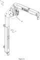
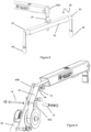
Figure 1 shows a first isometric view of a hoist mechanism; -
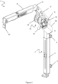
Figure 2 shows a second isometric view of a hoist mechanism; -
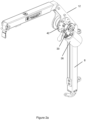
Figure 3 shows a first close-up view of a mounting bracket; -
Figure 4 shows a second close-up view of a mounting bracket; -
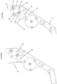
Figures 5-7 show a section view of a locking mechanism; -
Figure 8 shows a connection member of the hoist; -
Figure 9 shows an exploded view of a roller arrangement of the hoist; -
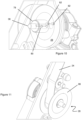
Figures 10-13 show partial close up views of a spool arrangement of the hoist; -
Figures 14-17 show details of a clamping member of the hoist; -
Figures 18a -c show a controller for controlling the hoist; -
Figure 19 shows a control box for controlling the hoist; -
Figure 20 shows a plug for the controller or control box. -
Figures 1 and2 show a hoistmechanism 2 for lifting a powered or non-powered mobility aid into a vehicle. For example, the powered or non-powered mobility aid may comprise a mobility scooter, electric wheelchair, manual wheelchair and/or other walking aids required by people with reduced mobility. Although the present invention is intended to lift such mobility aids, it can be appreciated that the user may use the hoist to the lift other heavy loads, as required. - The hoist
mechanism 2 is configured to be fixed to the vehicle adjacent a door or other opening, for example, a boot/trunk door, to allow the user to place the load inside the vehicle. - The hoist
mechanism 2 comprises a boom generally indicated at 4. Theboom 4 is configured to be rotationally attached to the vehicle. Theboom 4 comprises a plurality ofconnectors 6 to allow a connection to a post or other fixture within in the car. Theconnectors 6 comprise apertures/loops to permit rotation relative to the post. The hoist 2 may therefore be stored inside the vehicle when not in use and then swung out of the vehicle when required. A rotatable connection may also be provided at a base of theboom 4. The boom is thus swivelable as a whole about an upright/vertical. - The
boom 4 comprises a metallic beam, for example, a steel box-section. - The
connectors 6 are connected to afirst boom member 8, i.e. such that the first boom member is secured in an upright, e.g. vertical, orientation within the car. - A
second boom member 10 is telescopically connected to the first boom member 8 (i.e. slidable relative thereto), thereby allowing height adjustment of the hoistmechanism 2 in use. This allows users to adjust the hoistmechanism 2 according to the height of the vehicle interior. The first 8 and second 10 boom members thus form an upright, height-adjustable mast. - A
third boom member 12 is connected to thesecond boom member 10. The third boom member is attached at its proximal end to thesecond boom member 10, e.g. to the mast. - The
third boom member 12 is angled with respect to the first and second boom members forming the mast, such that an elongate axis of the third boom member forms an angle with respect to the elongate axis of the first/second boom member. Thethird boom member 12 is typically obliquely angled when in use and may form an interior angle of greater than or equal to 90° but less than 180° (e.g. offset from the mast by 45 degrees, or an interior angle of 135°). - A
fourth boom member 14 is connected to thethird boom member 12 at its distal end. Thethird boom member 12 thus forms an intermediate member between the mast andfourth boom member 14. - The fourth boom member is angled with respect to the
third boom member 12, such that an elongate axis of the third boom member forms an angle with respect to the elongate axis of the fourth boom member. Thefourth boom member 12 is typically obliquely angled from the third boom member and may form an interior angle of greater than or equal to 90° but less than 180° (e.g. offset by 45 degrees, or an interior angle of 135°). Thefourth boom member 14 extends in a substantially horizontal direction in use (e.g. is perpendicular to the first/second boom members). - A
fifth boom member 16 is telescopically connected to thefourth boom member 14, e.g. oriented along a common axis. The fourth and fifth boom members thus define a length-adjustable armature. - The
boom 4 is therefore extendible in two orthogonal directions (i.e. horizontal and vertical) by virtue of the length-adjustable mast and armature. - In a first embodiment shown in
figure 1 , the angular orientations of the boom members making up theboom 4 is substantially fixed/rigid. As shown infigure 3 , the second, third and fourth boom member may be formed from a single, unitary piece, thereby preventing relative rotation there-between. - In a second embodiment shown in
figure 2 , at least one of the second 10 and fourth 14 boom member is configured to allow selective angular adjustment with respect to the third/intermediate boom member 12 (e.g. to provide a rotatable joint). The joint allows rotation about a substantially horizontal axis formed at the interface between the respective adjacent boom members. - The joint is provided in this example between the mast (first/second boom member) and an upper armature (provided by the third, fourth and fifth boom member) of the
boom 4 bypivot 18 there-between. That is to say, the pivot is provided between the second 10 and third 12 boom members. - A
locking mechanism 20 locks the adjacent boom members into a fixed orientation, operation of which will be described later. Thelocking mechanism 20 comprises ahandle 22 to provide release of the locking mechanism. Thelocking mechanism 20 is described in further detail later. - Webbing, referred to herein as a
belt 24, depends from theboom structure 4 over the distal/free end of thefifth boom member 16 and is configured to be attached to the article to be lifted, e.g. a mobility scooter. - An
actuator 26, in the form of an electric motor, is mounted to theboom 4 structure. In this example theactuator 26 is mounted to the intermediate/third boom member 12 along with a spool for thebelt 24. The actuator comprises an electric motor oriented substantially in parallel with the boom member to which it is mounted, e.g. having an output shaft that rotates about an axis that is substantially parallel with the elongate axis of the boom member). - The
actuator 26 may draw power from the vehicle's on-board electric system. - The
belt 24 is operatively connected to anactuator 26 to retract/extend thebelt 24. Thebelt 24 extends through/along a hollow interior theboom 4, e.g. throughboom members belt 24. - The
belt 24 is connected to aspool 28 and thebelt 24 is configured to be wound to/from thespool 28 by theactuator 26. The hoist 2 therefore provides a winch like arrangement for selective payout/retraction of thebelt 24. - Upon a predetermined degree of retraction (e.g. when fully retracted), a locking mechanism (not shown) may lock the
actuator 26 and/or thespool 28 in place. For example, a locking pawl/arm may act on a toothed/gear of the spool, and/or theactuator 26 may comprise a rotational position lock (i.e. a lock built into the motor). The locking mechanism may be unidirectional, e.g. locking in a direction of passive payout of the belt. This prevents unwinding of thebelt 24 when power is not supplied to the actuator 26 (e.g. when loaded into the vehicle). The locking mechanism may automatically lock theactuator 26 and/or thespool 28 when a desired retracted position is reached. Alternatively, the locking mechanism may be manually applied by the user. The locking mechanism may comprise a ratchet or the like. The locking mechanism can be automatically released by power supplied to the actuator when lowering/raising the scooter (i.e. during extension of the belt 24). - In other embodiments, a different webbing type may be used to attach to the scooter, for example, a chain, a rope, or the like.
- The
actuator 26 comprises agearbox 30 connecting to thespool 28 to theelectric motor 26. Thegearbox 30 can be tuned to provide the appropriate rate of rotation for thespool 28 and/or force of retraction etc., as is conventional. Additionally or alternatively, thegearbox 30 allows a change of the axis of rotation between the actuator 26 and thespool 28. This allows mounting of theactuator 26 on the side of theboom 4, and/or parallel with a boom member, thereby providing a compact configuration. Thegearbox 30 output shaft may be perpendicular to its input shaft and/or the output shaft of the electric motor. - As shown in
figures 3 and4 , a mountingbracket 32 is configured to extend between the adjacent second/third/fourth boom members. Thebracket 32 is provide on the side of the boom. Thebracket 32 is attached to theboom 4 via a plurality offasteners 34. Thebracket 32 is therefore removable, for example to allow access to thespool 28 etc. Thebracket 32 is shaped to cover/enclose thespool 28, i.e. for mounting of the spool relative to the respective boom member. - The
bracket 32 is configured to support aspindle 38 configured to drive thespool 28. An opening in thebracket 32 receives thespindle 38. Asecondary bracket 32a is mounted onto thebracket 32 on an opposing side ofboom 4 to themotor 26. The secondary bracket comprises a plurality ofapertures 33a provide selective attachment of thesecondary bracket 32a to thebracket 32 via aplurality fasteners 33b. This allows swapping of the position of themotor 26 on either side of the boom, thus allowing multiple configurations of the boom in a vehicle. Additionally, this provides a significantly increased ease of maintenance. - The
secondary bracket 32a comprises abearing 40 configured to support thespindle 38, thereby permitting rotation of the spindle relative to thebracket 32 and secondary bracket 33. The bushes comprise a low friction material, to provide low resistance rotation of the roller 66 on the standoff 72 (i.e. a dry bearing). The bushes comprise a self-lubricating material, for example, oil-impregnated sintered bronze/iron (e.g. Oilite (RTM) bushes). Supporting the shaft on asingle bearing 40 reduces any alignment issues caused, for example, if a bearing place on both thebracket 32 on each side of theboom 4. Improved alignment of the shaft reduces motor noise and vibration; extends motor life; and minimises the power needed to lift a given load - A mounting
bracket 32 is provided each side of theboom 4. Thespindle 38 therefore spans thebrackets 32 and is supported thereby. A fastener comprising astandoff 34a extends through theboom 4 and connectsbracket 32 mounted on opposing sides thereof. Thestandoff 34a increases the clamping force between the opposingbrackets 32. - The
bracket 32, as well as providing a mounting structure for thespool 28, may reinforce the corner of theboom 4, i.e. providing a rigid structure spanning the interface between two adjacent boom members. Thebracket 32 thus provides a mounting bracket. - Best seen in
figure 2 , a fixingplate 42 is connected to thebracket 32 at an outer side thereof and adjacent thegearbox 30. The fixingplate 42 provides a mounting point for thegearbox 30 and/or motor, i.e. theactuator 26. Theactuator 26 is therefore held on theboom 4 via the gearbox (e.g. via a housing thereof) and the mountingbracket 32. The fixingplate 42 may be removably mounted to the bracket 32 (e.g. via fasteners or the like). In other embodiments, the fixingplate 42 may be integral with thebracket 32. In this way, theactuator 26 has a single mounting point that is common with the spool fixture. Additionally, the fixing plate evenly distributes the load from the gearbox/motor, thereby preventing deformation of the mountingbracket 32. - The mounting
bracket 32 provides a firm and rigid base to mount theactuator 26 and thegearbox 30. This ensures thespindle 38 is aligned with the axis ofspool 28. Any misalignment of thespindle 38 and thespool 28 may cause additional an additional load on theactuator 26, thus thebrackets 32 mitigate this issue. - Where the
boom 4 comprises a joint, thepivot 18 can be formed between thebracket 32 and thesecond boom member 10. Thebracket 32 therefore connects the rotatable boom members. A pin 44 extends betweenbracket 32 on either side of theboom 4 and though thesecond member 10, thereby connecting the mountingbracket 32 and thesecond boom member 10. A bearing or the like may be provided between the pin 44 and thesecond boom member 10 to aid rotation thereof. - The
third boom member 12 may be formed of, or comprise, the bracket(s) 32. - Operation of the
locking mechanism 20 is described with reference tofigures 5-7 . - The
handle 22 is connected to alever 46. Thehandle 22 extends from the level at an angle thereto, e.g. approximately perpendicularly or at an acute angle, and comprises a tab-like member. - The
lever 46 is rotationally connected to the mountingbracket 32 viapivot 48. Thelever 46 is substantially L-shaped or V-shaped, e.g. with the pivot provided at the apex. Thehandle 22 is connected to a first end of thelever 46 and/or to one side of the pivot. An opposing end of thelever 46, e.g. on the other side of the pivot comprises apin 50 in this example. - The
handle 22 andpin 50 could be on the same side of the pivot in other examples at different radial spacings from the pivot. - In an extended position shown in
figure 5 , thepin 50 is received within agroove 52 in anengagement member 53 depending from thepivot 18 and/or second boom member 10thesecond boom member 10. The engagement of thepin 50 and thegroove 52 prevents relative movement of the mounting bracket and thesecond boom member 10, and therefore prevents relative movement between the upper and lower portion. - The
groove 52 is open ended and extends in a downward direction away from the open end, e.g. to provide an engagement formation for receiving thepin 50. Thegroove 52 angled with respect to the axis of thesecond boom member 10 in a direction toward the rotation of the upper portion. As such, thepin 50 is biased into theend groove 52 by the weight of the upper portion (i.e. the upper portion is inclined to rotate under gravity such that thepin 50 goes into the groove 52). Additionally or alternatively, thepin 50 is biased into thegroove 52 by a torsion spring or the like extending between thelever 46 and the mounting bracket. Thegroove 52 in theengagement member 53 therefore provides a hook or latch type arrangement. - As shown in
figure 6 , to unlatch the joint, thelever 46 is rotated by pressing onhandle 22, such that thepin 50 moves along thegroove 52 to its open end. Thepin 50 moves beyond thegroove 52 end under the lever action until it is no longer in engagement therewith. Thepin 50 is therefore unlatched. The rotatable portion of the boom armature (i.e.boom members - As shown in
figure 7 , the upper portion of theboom 4 may then be released such that it can move downwards due to gravity. As thelever 46 has been rotated thepin 50 does not re-engage thegroove 52. Thepin 50 engages a curved/can surface 54 defined by an edge of theengagement member 53, and slides there along. Thecurved surface 54 is arcuate, such thepin 50 follows thesurface 54 during rotation of the upper portion. - The
surface 54 comprises alip 56 or stop portion at an end thereof. Thepin 50 engages thelip 56, preventing further movement of thepin 50. Thelip 56 therefore holds the upper portion in a predetermined, retracted/lowered position. In this regard theengagement member 53 may comprise first and second engagement formations for engaging the pin in raised and lowered conditions. - In the lowered position, the
third boom member 12 is substantially horizontal, and therefore the hoist 2 occupies less space. - To restore the upper portion back to the extend position, the user can raise the rotatable portion of the boom armature upward. The
pin 50 slides along the curved surface until thepin 50 is adjacent thegroove 52. The user then rotates thelever 46 or falls under gravity, such that thepin 50 enters thegroove 52. - In other embodiments, the
lever 46 andpin 50 arrangement may be provided on the lower power (i.e. the second boom member 10), with thepin 50 engaging agroove 52 on the upper portion. - As shown in
figure 8 , thebelt 24 comprises aconnection member 58 to allow connection of thebelt 24 to the scooter. Theconnection member 58 comprises a cross-bar or spreader-bar 60, arranged to be substantially horizontal use.End portion 62 are telescopically connected to the cross-bar 60, allowing variation of the width of theconnection member 58.Connecters 64, such as shackles, karabiners or the like, are provided on eachend portion 62 to allow a removable connection to lifting points on the scooter. -
Figure 9 shows an exploded, part-cut-away view through thethird boom member 12 andfourth boom member 14 and the belt spool and support members. Thebelt 24 runs from the end offifth boom 16 to thespool 28 via the inside of thefifth boom member 16 and thefourth boom member 12. - The
belt 24 is supported by a roller 66 at one or more location along the path between the spool and distal end of the boom, e.g. where thebelt 24 changes direction of travel. For example, afirst roller 66A is provided at the end of the boom (seefigure 8 ), asecond roller 66B at the intersection of the third and fourth boom member, and athird roller 66C adjacent thespool 28, e.g. controlling the direction of the belt running off the spool. - The/each roller 66 comprises a
cylindrical surface 68 configured to engage and support thebelt 24. The roller 66 comprises side walls or rims 70 one opposing sides of theintermediate surface 68 configured to bound/enclose thesurface 68. Theside walls 70 therefore ensure alignment of the belt on the roller surface when under load and prevent thebelt 24 from slipping off the roller 66. This has been found to be particularly important under high loading and/or camber as it has been found that a belt can slip partially off conventional rollers, thereby causing the load to be exerted on the belt via a roller edge or bolt threads, which can cause the roller edge to cut into the belt. Additionally, any slipping of thebelt 24 may cause additional load on theactuator 26. - The roller 66 is mounted to the
boom 4 via a standoff 72 (i.e. a fixed roller/spacer) received within the roller 66. The standoff is mounted to the boom via afastener 74. The roller 66 is mounted directly on the standoff 72 (i.e, there is no intermediate bearing). The roller 66 may rotate over the standoff via the natural lubricating properties of the roller 66 and/or standoff 66. For example, the roller 66 and/or standoff may comprise a low friction material, such as nylon. The rollers 66 are therefore low maintenance and reduce wear on thebelt 24 and/or bearings. - In alternative embodiments, a pair of bushes support the roller 66 on the standoff. The bushes comprise a low friction material, to provide low resistance rotation of the roller 66 on the standoff 72 (i.e. a dry bearing). The bushes comprises a self-lubricating material, for example, oil-impregnated sintered bronze/iron (e.g. Oilite (RTM) bushes).
- In other embodiments, the roller 66 is mounted to the
standoff 72 via conventional ball bearings. - As shown in
figure 10 , thespool 28 comprises ahub 78. Thehub 78 is attached to thebelt 24, such that thebelt 24 is configured to wrap around thehub 78 during winding thereof. As shown infigure 10 , thehub 78 comprises a plurality ofapertures 80 extending there-through. Theapertures 80 extend in a substantially redial direction, such that a pin/screw 82 may be inserted into the aperture and into engagement with a groove 84 on thespindle 38. Thehub 78 is therefore rotationally fixed to thespindle 38 via theremovable pin 82. - As shown in
figures 11-13 , thehub 78 comprises a plurality ofside walls 86 at either end thereof. Theside walls 86 may be separated by a distance substantially the same as the width of thebelt 24, therefore preventing lateral movement of thebelt 24. Thehub 78 andside walls 86 therefore provide a "bobbin" like arrangement. Theside walls 86 may be removably attached to thehub 78 to allow insert/removal of thebelt 24. Theside walls 86 rotate with thehub 78/spindle 38. Theside walls 86 therefore prevent wear of the edges of thebelt 24. An end of thehub 78 may protrude outwardly from the surface of the side walls 86 (seefigure 11 ). For example the end may protrude by between 1 mm and 5mm. - The
hub 78 comprises a connection assembly to allow removable connection of thebelt 24 to thehub 78/spindle 28. Thehub 78 comprises arecess 88 extending along the axial length thereof. Therecess 88 is configured to accommodate the width of thebelt 24. At least oneend wall 90 of thehub 78 comprises anaperture 92 opening into the recess 88 (i.e. such therecess 88 at least partially extends into one or both of the end walls 90). An end of thebelt 24 comprising a loop or the like is inserted into therecess 88. Apin 94 is then inserted along the length of therecess 88 via theaperture 92. Thepin 88 is passed through the loop in the belt. Thepin 94 is then retained in place by theaperture 92 and/or a groove in one or both of theend walls 90. Thebelt 24 is therefore secured to thehub 78. - To detach the
belt 24 from thehub 78, thepin 94 is removed. Thepin 94 is accessible from the outer side of thespool 28, so thebelt 24 may be detached without removing thespool side walls 86. - The
hub 78 is operatively positioned between the mountingbrackets 32 on either side thereof. The fixed length of thehub 78 therefore maintains the spacing of the mountingbrackets 32. This prevents thebrackets 32 from engaging thespool 28 and generating additional load on theactuator 26. Thehub 78 increases the tolerances between thespool 28 and brackets and therefore can accommodate twisting and/or bending of the joint between the arms. Thehub 78 may be wider than the spool 27 to maintain a desired spacing of thebrackets 32. -
Figures 14-17 show the telescoping arrangements of the upper portion and the lower portion of theboom 4. - As shown in
figure 15 , thefirst boom member 8 comprises anaxial slot 96 extending along the length thereof. The length ofaxial slot 96 defines the length of the extension/retraction of the mast. As best seen infigure 17 , thesecond boom member 10 comprises a plurality ofapertures 98 to receive a plurality ofrespective fasteners 100. Theapertures 98 comprise rivet nuts. A clampingplate 102 is placed intermediate the fasteners and thefirst boom member 8. The fasteners pass from the clampingplate 102 to connect to theapertures 98. The clampingplate 102 therefore provides a clamp configured to grip thefirst boom member 8, preventing relative movement between thefirst boom member 8 and thesecond boom member 10. The clampingplate 102 increases the effective area of contact between the first and second boom members, reducing the likelihood of damage and/or marking of the boom members. - A similar arrangement is provided on the upper portion of the
boom 4. Likewise anaxial slot 104 is provided in thefifth boom member 16 and aclamping plate 106 clamps thefourth boom member 14 and thefifth boom member 16 in position. -
Figures 18a-c shows acontroller 108 for controlling operation of the hoist 2. Thecontroller 108 comprises a plurality ofbuttons 110 to allow selection of one or more operations. For example, a first button to lower thebelt 24, a second button to raise thebelt 24 and/or a power button etc. Additional buttons may be provided to rotate/swivel the boom for about the upright axis, e.g. where a suitable actuator is installed. In other examples, swivelling rotation is effected manually. - The
buttons 110 are provided in a large and/or spaced format (i.e. there is a gap provided between the buttons), to allow easy operation for those with reduced dexterity. Thebuttons 110 are configured to illuminate when pressed (e.g. by anindicator 112 embedded therein, or provided behind/within the button). Thecontroller 108 comprises a magnet and/or magnetic material configured to connect to a magnet/magnetic material on the hoist 2 and/or vehicle, thus allowing convenient stowing of thecontroller 108. - The
controller 108 comprises an indicator 114 (e.g. an LED, buzzer/speaker or the like) to alert the user of one or more condition of the hoist 2, e.g. if it requires a service. - Requirement for a service may be determined by one or more factors: a fixed period of time (e.g. a service is required at fixed intervals regardless of usage); number of lifting/lowering cycles; period of time hoist is in actual operation (e.g. amount of time actuator is running); the number of times the hoist assembly is powered on and/or off; or other factors indicating the usage of the hoist 2.
- The
controller 108 is connected to control box 116 (seefigure 19 ). Thecontrol box 116 is configured to receive instructions from thecontroller 108 and control theactuator 26 accordingly. Thecontrol box 116 is operatively connected to the vehicle power supply, to provide power to drive theactuator 26. The connections between thecontrol box 116,controller 108 and/oractuator 26 may be disconnectable (e.g. via a plug/socket arrangement). As shown infigure 20 , theplug 118 comprises a large form factor connection, for example, a Molex (RTM) connector. Theplugs 118 are loosely held within the socket (e.g. via interference fit) and therefore can be inserted/removed with a push/pull action. Theplug 118 can therefore easily be removed without the user needing to uncouple latches etc. In alternative embodiment, latches or the like may be used to secure theplug 118. The plugs/sockets may be colour coded to ensure the correct plug is used with the respective socket. - The
control box 116 comprises a computer (e.g. a programmable micro-controller/microprocessor) configured to determine when the service is required. The computer may have a clock and/or store date/time information, therefore allowing calculation of any service periods. Additionally or alternatively, the computer is configured to count the number of lifting cycles, power cycles (e.g. on/off button presses) and/oractuator 26 usage. On the event a service condition is met, then controlbox 116 illuminates theindicator 114. - The
controller 108 and/orcontrol box 116 are waterproof and/or comprise a waterproof casing. - The
control box 116 is configured to detect when the actuator experiences a load above a predetermined threshold. For example, this may indicate theactuator 26 is overburdened (e.g. the scooter is too heavy) and/or when the belt is fully retracted. Thecontrol box 116 is configured to monitor the electrical characteristics of theactuator 26 or electrical supply thereto during operation thereof. - The
control box 116 may monitor one or more of: the current drawn, the voltage, the impedance or the capacitance of the power supply to theactuator 26 or theactuator 26 itself. The sensed values and/or a rate of change in the sensed values may be monitored. If an abnormal electrical characteristic or behaviour is detected (i.e. lies outside of a predetermined threshold or range or abnormal rate of change), operation of theactuator 26 may be ceased and/or the power to the actuator may be limited/reduced. - For example, if the current increases beyond a threshold (e.g. spikes), this may indicate the belt is fully retracted or the motor is being overloaded for some other reason. The power (i.e. current) to the
actuator 26 is then cut-off. This allows control of theactuator 26 to be adapted accordingly to the load thereon. Additionally or alternatively, this prevents theactuator 26 continuing to the run when the belt is fully retracted, i.e. when an end member of the belt abuts the distal end of the boom, which may prevent motor burn out or blown fuses. - In the examples disclosed herein, electrical current is used as a proxy for the mechanical overloading of the motor, e.g. for identifying stall of a very small rotation of the rotor indicative of a condition in which the motor is struggling to generate sufficient torque to wind the webbing at a normal rate. In other examples, a torque sensor could be used or else a rotation speed sensor for the motor, gearbox and/or spool either instead of, or in addition to, current sensing.
- Additionally or alternatively, the system may be configured to determine the extent of retraction of the
belt 24. This may be performed in a number of ways: - measuring the number of revolutions of the actuator/spool;
- measuring the time actuator is active (in concert with the speed setting of the actuator if applicable);
- and/or providing one or more marking/indicator on the
belt 24 and detecting the position of the marking/indicator. - The current and/or extent of retraction may be determined using a Hall effect and/or Reed sensor. The Hall effect/Reed sensor may determine the current supplied to actuator by measuring the magnetic field generated by the current passing through the power supply and/or actuator. Additionally or alternatively, the Hall effect/Reed sensor may be used to determine the position of one or more magnets in the actuator (i.e. in an electric motor). The Hall sensor may therefore be used to calculate the number of revolutions performed by counting the number of passes the one or more magnets make past the sensor.
- In prior art devices, a large or high power actuator is used to accommodate a safety margin in the load that may be experienced by the motor to prevent burn-out of failure of the actuator. The load measuring system and/or the retraction system eliminate the need or reduce the size of the margin required, thereby allowing a smaller or low power actuator.
- When the electric motor is not energised, a locking mechanism for the spool, gearbox and/or motor may be engaged to prevent payout of the belt, e.g. when a scooter is partially or fully suspended by the hoist. Additionally or alternatively it may be possible for the controller to retain the motor in an energised condition but without rotating the output shaft to thereby resist payout of the belt in an uncontrolled manner.
- The computer of the
control box 116 is programmable, e.g. to change thresholds or functionality. For example, limits may be set using thecontroller 108 or other input means. In some models, additional sensors may be used to determine the control functionality. For example, the length of payout of the belt may be sensed, e.g. by sensing rotation of the spool and/or roller. In other examples, the motor and/or computer may set a datum point when the belt is fully retracted, e.g. in a strartup mode of operation, and may use the datum point or the rotation of the motor, gearbox and/or spool relative to the datum point as a further control measure. - In other examples, a sensor or electrical cut-out on the
locking mechanism 20 could be used to prevent/allow operation of the motor when the locking mechanism is disengaged/engaged respectively. - The controller may monitor ongoing usage of the hoist and/or maintain a log of one or more usage parameter, e.g. in a non-volatile memory. The controller may increment the log according to and/or during an instance of use of the hoist/actuator. The controller may compare the log against one or more predetermined criterion in order to output an indication of the operational health of the hoist. The controller may be configured to indicate whether a service of the hoist is required according to one or more service condition determined by the controller. For example the controller may maintain a simple count of the number of instances of use of the hoist/actuator. Additionally/alternatively, the controller may maintain a log of duration of operation of the motor and/or loading (e.g. by way of current sensing). The controller may log the number and/or frequency of overloading events and may indicate if a degradation in performance is determined.
- The present invention provides a low maintenance hoist with a reduced likelihood of damage to the lifting belt or other components. The rotating joints are self-lubricating, therefore mitigating the need to lubricants etc. The hoist is adjustable in a simple fashion that prevents damage or marking of the boom.
- The motor may be placed on either side of the boom, thus allowing the device to be used in a plurality of different vehicles. The mounting bracket arrangement reduces the torque forces on the boom and/or spool, thereby reducing wear and damage to the motor. The use of dry bearings ensures the device is easy to assemble/disassemble (e.g. no oil mess) and requires no maintenance.
- The hoist is easy and simple to use and control for people with reduced dexterity and is resistant to rain or other spills. The hoist comprises a self-limiting actuator, and the roller and spool are configured to be low friction and to reduce unnecessary loads on the actuator. The risk of burn out of the motor is prevented, increasing the safety of the hoist and reducing the likelihood of over-heating or fire etc. This allows the use of a smaller motor, thereby reducing the weight and increasing the compactness of the system. The hoist automatically informs the user when a service is due.
- The hoist is collapsible therefore providing a more compact configuration and use in a wider range of vehicles. The mechanism to collapse the hoist is simple to use, for example, it can be actuated using only the large handle, without fiddly or complex movements (e.g. twisting) which may be difficult for some users.
Claims (14)
- A hoist mechanism (2) for lifting articles into/from an interior of an automobile vehicle, the hoist mechanism (2) comprising:a boom (4) arranged to be mounted on the vehicle;a length of webbing (24) depending from the boom (4) and configured to be attached to the article to be lifted in use;a spool (28); andan electric motor (26) configured to retract the webbing (24) to provide lifting of the article by winding the webbing (24) onto the spool (28),wherein the boom (4) comprises a first mounting bracket (32) mounted on a first side of the boom (4) and a second mounting bracket (32) mounted on a second, opposing side of the boom (4) and the spool (28) is supported between the first and second mounting brackets (32), and characterised in thatthe electric motor (26) is selectively mountable to each of the first mounting bracket (32) and the second mounting bracket (32) respectively, such that the spool (28) is mounted to one side of the first or second mounting bracket (32) and the electric motor (26) is mounted on the other side of said first or second mounting bracket (32).
- A hoist mechanism (2) according to claim 1, where the motor (26) is supported on the first or second mounting bracket (32) via a further bracket (32a) mounted to the first or second mounting bracket (32) opposing the motor (26).
- A hoist mechanism (2) according to claim 2, where the further bracket (32a) comprises an aperture therein configured to support the spool and/or a dry bearing (40) configured to support the spool (28).
- A hoist mechanism (2) according to any preceding claim, comprising a controller (108) configured to supply power to the electric motor (26) for actuation thereof, the controller (108) further configured to monitor one or more electrical parameter of the electric motor (26) or the power supply thereto, determine whether the one or more electrical parameter is within one or more predetermined thresholds, and to selectively control the power supply to the electric motor (26) according to said determination.
- A hoist mechanism (2) according to claim 4, where the controller (108) is configured to reduce or deny power to the electric motor (26) when the one or more monitored electrical parameters is outside of said threshold, the one or more electrical parameters comprising an operational variable indicative of power, rotation, torque or work done by the electric motor (26).
- A hoist mechanism (2) according to any preceding claim, comprising a log of one or more usage parameter in a non-volatile memory, the log being incremented according to and/or during an instance of use of the electric motor so as to monitor ongoing usage of the hoist (2), wherein a controller (108) compares the log against one or more predetermined criteria in order to output an indication of the operational health of the hoist (2).
- A hoist mechanism (2) according to any one of claims 4-6, where the controller (108) is configured to indicate whether a service of the hoist (2) is required according to one or more service conditions determined by the controller (108).
- A hoist mechanism (2) according to claim 6 or 7, where the one or more predetermined criteria or service conditions comprises one or more of: a predetermined period of time; a number of lifting/lowering cycles of the hoist (2); a number of times the hoist (2) is powered on/off; or a period of time the electric motor (26) is in use.
- A hoist mechanism (2) according to any preceding claim, further comprising a locking mechanism configured to lock the electric motor (26) and/or spool (28) selectively to prevent payout of webbing (24), e.g. when the controller (108) selectively denies or reduces power to the electric motor (26).
- A hoist mechanism (2) according to any preceding claim, where the boom (4) comprises a first portion (10) angled relative to a second portion (14), the mounting bracket spanning the first and second portion (10,14) and wherein one or both of the first and second portion (10,14) are extensible in a length direction.
- A hoist mechanism (2) according to any preceding claim, where the boom (4) comprises first and second pivotally connected arms (10,12), the first arm (10) being arranged to be mounted in an upright orientation within the vehicle and the second arm (12) moveable relative to the first arm (10) between a raised position and a lowered position so as to vary the angle defined between a longitudinal axis of each arm(10,12), the hoist mechanism (2) further comprising a releasable latching mechanism (20) configured to retain the second arm (12) in the raised position, the latching mechanism (20) comprising a lever (46) rotatably mounted to one of the first arm (10) and the second arm (12) about a pivot point (48) and having an engagement formation (50), the engagement formation (50) being releasably engageable with an opposing engagement formation (52) on the other of the first arm (10) and the second arm (12) in the raised position so as to prevent relative movement of the first and second arms (10,12), the lever (46) being manually rotatable relative to the first and/or second arm (10,12) whilst in the raised condition to disengage the opposing engagement formations (50,52) to permit movement of the second arm (12) relative to the first arm (10) to the lowered position.
- A hoist mechanism (2) according to any preceding claim, comprising a hub portion (78) removably mounted to a rotatable spindle (38) driven by the electric motor (26), the spool (28) being mounted about the hub portion (78), for example the hub portion (78) comprising a recess (88) configured to receive an end of the webbing (24) and a retaining member (94) configured to extend through at a least a portion of the recess (88) to engage and secure the end of the webbing (24) within the recess (88), the retaining member (94) being removably engageable with the hub portion (78), such that the webbing (24) is removably secured to the hub portion (78).
- A hoist mechanism according to claim 12, where the retaining member (94) comprises a pin or screw configured to axially extend along the length of the hub portion (78) and is held in position via an aperture (92) in one or both of the ends of the hub portion (78).
- A hoist mechanism (2) according to claim to claim 12 or 13 where the hub portion (78) is configured to space the spool (28) from the mounting bracket (32) and/or where the hub portion (78) at least partially extends into and/or abuts the mounting bracket (32).
Applications Claiming Priority (1)
| Application Number | Priority Date | Filing Date | Title |
|---|---|---|---|
| GB2003138.1A GB2592628B (en) | 2020-03-04 | 2020-03-04 | Hoist mechanism |
Publications (2)
| Publication Number | Publication Date |
|---|---|
| EP3875069A1 EP3875069A1 (en) | 2021-09-08 |
| EP3875069B1 true EP3875069B1 (en) | 2024-07-10 |
Family
ID=70278648
Family Applications (1)
| Application Number | Title | Priority Date | Filing Date |
|---|---|---|---|
| EP21160821.1A Active EP3875069B1 (en) | 2020-03-04 | 2021-03-04 | Hoist mechanism |
Country Status (4)
| Country | Link |
|---|---|
| US (1) | US11510830B2 (en) |
| EP (1) | EP3875069B1 (en) |
| AU (1) | AU2021201429B2 (en) |
| GB (1) | GB2592628B (en) |
Families Citing this family (3)
| Publication number | Priority date | Publication date | Assignee | Title |
|---|---|---|---|---|
| CN115123049B (en) * | 2022-03-09 | 2024-09-27 | 德明尚品科技集团有限公司 | Pull arm type self-loading and unloading carriage |
| GB2627203B (en) * | 2023-02-14 | 2025-02-12 | Autochair Ltd | Battery mounting system |
| US20250277712A1 (en) * | 2024-03-01 | 2025-09-04 | Columbus Mckinnon Corporation | Load Sensing Device for a Hoist |
Family Cites Families (56)
| Publication number | Priority date | Publication date | Assignee | Title |
|---|---|---|---|---|
| US3804263A (en) | 1971-08-17 | 1974-04-16 | R Castonguay | Portable hoist |
| US3784035A (en) | 1972-04-17 | 1974-01-08 | G Dunbar | Vehicle mounted loading hoist |
| US3948488A (en) * | 1974-09-12 | 1976-04-06 | Dutton-Lainson Company | Mounting means for power anchor winch |
| US3957164A (en) * | 1974-10-16 | 1976-05-18 | Brown Joseph H | Wheelchair hoist and carrier |
| US3999228A (en) | 1975-10-10 | 1976-12-28 | Thomas Dale H | Invalid lifting and walking device |
| US4226331A (en) | 1977-08-08 | 1980-10-07 | Dumond Duane I | Hydraulically actuated hoist for tractors having a conventional three point hitch |
| US4272218A (en) | 1977-11-10 | 1981-06-09 | Carter Robert A | Apparatus for transporting a wheelchair upon an automobile |
| US4296509A (en) | 1979-10-23 | 1981-10-27 | Simmons Dwane P | Portable invalid lift |
| US4523684A (en) | 1982-09-30 | 1985-06-18 | Jerry Baisden | Crane tool for attachment to a backhoe arm |
| NL8302687A (en) | 1983-07-28 | 1985-02-18 | Zwagerman Jan | MOBILE CRANE. |
| US4736929A (en) * | 1986-06-30 | 1988-04-12 | Warn Industries, Inc. | Winch having split housing and drive components |
| US4881864A (en) | 1987-11-09 | 1989-11-21 | Hitch Lift, Inc. | Boom hoist for attachment to a trailer hitch drawbar |
| US5064078A (en) | 1989-09-26 | 1991-11-12 | Staveren John C Van | Combination portable hoist, crane, and vehicle towing apparatus |
| JPH03202059A (en) | 1989-12-28 | 1991-09-03 | Yoshio Asakawa | Bed device for medical treatment |
| US5090580A (en) * | 1990-09-10 | 1992-02-25 | Walbert O. Nelson | Trunk-mounted portable crane |
| US5431526A (en) * | 1992-07-06 | 1995-07-11 | Peterson; Edward A. | Lifting system for transporting vehicle |
| US5379468A (en) | 1993-04-26 | 1995-01-10 | Cassidy; Joseph P. | Patient-handling apparatus |
| US5337908A (en) | 1993-07-15 | 1994-08-16 | Beck Jr John R | Patient hoist |
| US5494117A (en) | 1994-01-24 | 1996-02-27 | Aldridge; B. Hunter | Metal fence post driver |
| US5445281A (en) | 1994-09-29 | 1995-08-29 | Hung; Michael | Light-duty electric crane |
| US5522582A (en) * | 1994-10-27 | 1996-06-04 | Warn Industries, Inc. | Remote controlled winch |
| IL111636A0 (en) | 1994-11-14 | 1995-01-24 | Rogozinski Joseph | Patient lifting and support systems |
| US5788095A (en) | 1995-10-20 | 1998-08-04 | Watson; Sammy | Offset boom and mast apparatus |
| JP2813871B2 (en) | 1995-12-05 | 1998-10-22 | 芳夫 浅川 | Sick transporter |
| US5848715A (en) | 1996-06-06 | 1998-12-15 | Swift Lift Inc | Combination roll bar and crane |
| US5853282A (en) * | 1996-08-01 | 1998-12-29 | Ranger All Season Corporation | Scooter lift |
| WO1999008955A1 (en) | 1997-08-19 | 1999-02-25 | Perrin, Doreen | Crane |
| US6045320A (en) | 1997-12-17 | 2000-04-04 | Cullen; Michael J. | Arm extension for a backhoe |
| US6138991A (en) * | 1998-03-23 | 2000-10-31 | Myers, Jr.; Robert | Vehicle-mounted hoist apparatus |
| US6202868B1 (en) | 1999-03-15 | 2001-03-20 | David N. Murray | Collapsible hoist |
| US6095349A (en) | 1999-06-08 | 2000-08-01 | Orm Consulting, Inc. | Knock-down hoist |
| US6631886B1 (en) * | 2001-07-11 | 2003-10-14 | Ramsey Winch Company | Winch housing with integral fairlead |
| US6830423B1 (en) * | 2002-12-18 | 2004-12-14 | Chadco Enterprises, Inc. | Personal mobility vehicle lift |
| US7377740B2 (en) * | 2003-04-22 | 2008-05-27 | Cook Technologies, Inc. | Lifting device for a personal-transportation vehicle |
| US6981834B1 (en) | 2003-05-30 | 2006-01-03 | James Louis Henry | Portable engine hoist |
| US20070086879A1 (en) * | 2003-11-18 | 2007-04-19 | Ronald Goodrich | Electronic control system and method for an auxiliary device interlock safety system |
| WO2005053178A1 (en) * | 2003-11-24 | 2005-06-09 | The Braun Corporation | Mobility hand control device and method |
| US8056674B2 (en) | 2004-02-26 | 2011-11-15 | Jlg Industries, Inc. | Boom lift vehicle and method of controlling lifting functions |
| US7657951B2 (en) | 2004-06-14 | 2010-02-09 | Ez Way, Inc. | Support and transfer apparatus for transport of an incapacitated individual |
| US7462138B2 (en) | 2005-07-01 | 2008-12-09 | The University Of Hartford | Ambulatory suspension and rehabilitation apparatus |
| GB2431631A (en) * | 2005-10-25 | 2007-05-02 | Proto Magic Innovations Ltd | Invalid hoist |
| US7370769B2 (en) * | 2006-04-25 | 2008-05-13 | Richard Picard | Hoist for retrieving and lifting loads |
| WO2012075270A2 (en) * | 2010-12-01 | 2012-06-07 | Cequent Performance Products. Inc. | Winch assembly |
| US7878484B2 (en) | 2009-02-06 | 2011-02-01 | Kitchens Sr James Larry | Vehicle-mountable hoist |
| US20110016628A1 (en) | 2009-07-21 | 2011-01-27 | Masterson Jr Russell P | Portable apparatus for moving subjects |
| US8231109B2 (en) * | 2009-10-13 | 2012-07-31 | I-Sin Peng | Reel structure for marine fabric tape |
| US8544824B2 (en) | 2011-06-15 | 2013-10-01 | Stephen L. Selkowitz | Foldable table lift assist apparatus |
| GB201117251D0 (en) | 2011-10-05 | 2011-11-16 | Autochair Ltd | Hoist mechanism |
| KR101296890B1 (en) * | 2012-11-13 | 2013-08-14 | (주)코스텍 | Drum bracket for stage apparatus with speed reduction motor |
| US9327947B2 (en) | 2012-11-26 | 2016-05-03 | Mickel Davis | All-terrain vehicle lifting crane apparatus |
| US9014913B2 (en) * | 2013-03-08 | 2015-04-21 | Warn Industries, Inc. | Multi-mode radio frequency winch controller |
| ITFI20130306A1 (en) * | 2013-12-27 | 2015-06-28 | Davide Nardini | DEVICE FOR MOVING BED STRUCTURES. |
| US20150307332A1 (en) * | 2014-04-28 | 2015-10-29 | Comeup Industries Inc. | Power Winch Display Panel |
| US20170137265A1 (en) | 2015-11-13 | 2017-05-18 | Keith Menville | Portable Apparatus For Lifting Objects |
| GB201619491D0 (en) * | 2016-11-17 | 2017-01-04 | Autochair Ltd | A hoist mechanism and a stepless adjustment means |
| US11014791B2 (en) * | 2018-04-05 | 2021-05-25 | Vermeer Manufacturing Company | Self-raising winch boom and control systems and methods associated therewith |
-
2020
- 2020-03-04 GB GB2003138.1A patent/GB2592628B/en active Active
-
2021
- 2021-03-04 US US17/191,880 patent/US11510830B2/en active Active
- 2021-03-04 AU AU2021201429A patent/AU2021201429B2/en active Active
- 2021-03-04 EP EP21160821.1A patent/EP3875069B1/en active Active
Also Published As
| Publication number | Publication date |
|---|---|
| US20210275367A1 (en) | 2021-09-09 |
| AU2021201429B2 (en) | 2025-11-13 |
| US11510830B2 (en) | 2022-11-29 |
| GB2592628B (en) | 2023-02-01 |
| GB2592628A (en) | 2021-09-08 |
| EP3875069A1 (en) | 2021-09-08 |
| GB202003138D0 (en) | 2020-04-15 |
| AU2021201429A1 (en) | 2021-09-23 |
Similar Documents
| Publication | Publication Date | Title |
|---|---|---|
| EP3875069B1 (en) | Hoist mechanism | |
| US8403302B2 (en) | Elevated support system | |
| US7469881B2 (en) | Hoist with detachable power and control unit | |
| US7434787B2 (en) | Winch for raising and lowering persons | |
| US20200140245A1 (en) | Electric hoisting machine and control device and control method therefor | |
| WO2011134062A1 (en) | 360-degree freedom electric cord device and system | |
| KR102577629B1 (en) | Engineroom hoist unit | |
| US9463965B2 (en) | Pulling tool | |
| US5848641A (en) | Well pump puller | |
| US20240262278A1 (en) | Actuator and lift system for a camper trailer | |
| EP3746392B1 (en) | Lifting device comprising a housing allowing for easy access to the interior of the lifting device | |
| US9156665B2 (en) | Pulling tool | |
| US3863859A (en) | Reel support and winder apparatus | |
| CN116905884B (en) | Intelligent tension rod for assembling high-voltage distribution line | |
| EP1877614A2 (en) | Motor-driven clothes dryer and drive device for a washing dryer | |
| CN213923847U (en) | Take-up device and hand-operated clothes hanger with safety protection function | |
| CN115074970A (en) | Airing machine with function is hidden to pole that dries in air | |
| EP1373121B1 (en) | Automatic locking device for a lifting block | |
| CN112299269A (en) | Take-up device and hand-operated clothes hanger with safety protection function | |
| CN223163104U (en) | Power line construction is with motor winch | |
| JP2503141B2 (en) | Crane wire rope terminal fixing device | |
| WO2024064652A1 (en) | Hitch mount for hoist | |
| CN113753750A (en) | Safety device for hoisting of outer wall | |
| JPH0678175U (en) | Suspended tire carrier | |
| JP2002125285A (en) | Electric hanging microphone device and its safety device |
Legal Events
| Date | Code | Title | Description |
|---|---|---|---|
| PUAI | Public reference made under article 153(3) epc to a published international application that has entered the european phase |
Free format text: ORIGINAL CODE: 0009012 |
|
| STAA | Information on the status of an ep patent application or granted ep patent |
Free format text: STATUS: THE APPLICATION HAS BEEN PUBLISHED |
|
| AK | Designated contracting states |
Kind code of ref document: A1 Designated state(s): AL AT BE BG CH CY CZ DE DK EE ES FI FR GB GR HR HU IE IS IT LI LT LU LV MC MK MT NL NO PL PT RO RS SE SI SK SM TR |
|
| STAA | Information on the status of an ep patent application or granted ep patent |
Free format text: STATUS: REQUEST FOR EXAMINATION WAS MADE |
|
| 17P | Request for examination filed |
Effective date: 20220308 |
|
| RBV | Designated contracting states (corrected) |
Designated state(s): AL AT BE BG CH CY CZ DE DK EE ES FI FR GB GR HR HU IE IS IT LI LT LU LV MC MK MT NL NO PL PT RO RS SE SI SK SM TR |
|
| GRAP | Despatch of communication of intention to grant a patent |
Free format text: ORIGINAL CODE: EPIDOSNIGR1 |
|
| STAA | Information on the status of an ep patent application or granted ep patent |
Free format text: STATUS: GRANT OF PATENT IS INTENDED |
|
| INTG | Intention to grant announced |
Effective date: 20231127 |
|
| GRAJ | Information related to disapproval of communication of intention to grant by the applicant or resumption of examination proceedings by the epo deleted |
Free format text: ORIGINAL CODE: EPIDOSDIGR1 |
|
| STAA | Information on the status of an ep patent application or granted ep patent |
Free format text: STATUS: REQUEST FOR EXAMINATION WAS MADE |
|
| GRAP | Despatch of communication of intention to grant a patent |
Free format text: ORIGINAL CODE: EPIDOSNIGR1 |
|
| STAA | Information on the status of an ep patent application or granted ep patent |
Free format text: STATUS: GRANT OF PATENT IS INTENDED |
|
| INTC | Intention to grant announced (deleted) | ||
| INTG | Intention to grant announced |
Effective date: 20240315 |
|
| GRAS | Grant fee paid |
Free format text: ORIGINAL CODE: EPIDOSNIGR3 |
|
| GRAA | (expected) grant |
Free format text: ORIGINAL CODE: 0009210 |
|
| STAA | Information on the status of an ep patent application or granted ep patent |
Free format text: STATUS: THE PATENT HAS BEEN GRANTED |
|
| AK | Designated contracting states |
Kind code of ref document: B1 Designated state(s): AL AT BE BG CH CY CZ DE DK EE ES FI FR GB GR HR HU IE IS IT LI LT LU LV MC MK MT NL NO PL PT RO RS SE SI SK SM TR |
|
| REG | Reference to a national code |
Ref country code: CH Ref legal event code: EP |
|
| REG | Reference to a national code |
Ref country code: DE Ref legal event code: R096 Ref document number: 602021015337 Country of ref document: DE |
|
| REG | Reference to a national code |
Ref country code: LT Ref legal event code: MG9D |
|
| REG | Reference to a national code |
Ref country code: NL Ref legal event code: MP Effective date: 20240710 |
|
| PG25 | Lapsed in a contracting state [announced via postgrant information from national office to epo] |
Ref country code: PT Free format text: LAPSE BECAUSE OF FAILURE TO SUBMIT A TRANSLATION OF THE DESCRIPTION OR TO PAY THE FEE WITHIN THE PRESCRIBED TIME-LIMIT Effective date: 20241111 |
|
| REG | Reference to a national code |
Ref country code: AT Ref legal event code: MK05 Ref document number: 1701409 Country of ref document: AT Kind code of ref document: T Effective date: 20240710 |
|
| PG25 | Lapsed in a contracting state [announced via postgrant information from national office to epo] |
Ref country code: NL Free format text: LAPSE BECAUSE OF FAILURE TO SUBMIT A TRANSLATION OF THE DESCRIPTION OR TO PAY THE FEE WITHIN THE PRESCRIBED TIME-LIMIT Effective date: 20240710 |
|
| PG25 | Lapsed in a contracting state [announced via postgrant information from national office to epo] |
Ref country code: PT Free format text: LAPSE BECAUSE OF FAILURE TO SUBMIT A TRANSLATION OF THE DESCRIPTION OR TO PAY THE FEE WITHIN THE PRESCRIBED TIME-LIMIT Effective date: 20241111 Ref country code: NL Free format text: LAPSE BECAUSE OF FAILURE TO SUBMIT A TRANSLATION OF THE DESCRIPTION OR TO PAY THE FEE WITHIN THE PRESCRIBED TIME-LIMIT Effective date: 20240710 |
|
| PG25 | Lapsed in a contracting state [announced via postgrant information from national office to epo] |
Ref country code: NO Free format text: LAPSE BECAUSE OF FAILURE TO SUBMIT A TRANSLATION OF THE DESCRIPTION OR TO PAY THE FEE WITHIN THE PRESCRIBED TIME-LIMIT Effective date: 20241010 |
|
| PG25 | Lapsed in a contracting state [announced via postgrant information from national office to epo] |
Ref country code: FI Free format text: LAPSE BECAUSE OF FAILURE TO SUBMIT A TRANSLATION OF THE DESCRIPTION OR TO PAY THE FEE WITHIN THE PRESCRIBED TIME-LIMIT Effective date: 20240710 Ref country code: GR Free format text: LAPSE BECAUSE OF FAILURE TO SUBMIT A TRANSLATION OF THE DESCRIPTION OR TO PAY THE FEE WITHIN THE PRESCRIBED TIME-LIMIT Effective date: 20241011 Ref country code: PL Free format text: LAPSE BECAUSE OF FAILURE TO SUBMIT A TRANSLATION OF THE DESCRIPTION OR TO PAY THE FEE WITHIN THE PRESCRIBED TIME-LIMIT Effective date: 20240710 |
|
| PG25 | Lapsed in a contracting state [announced via postgrant information from national office to epo] |
Ref country code: BG Free format text: LAPSE BECAUSE OF FAILURE TO SUBMIT A TRANSLATION OF THE DESCRIPTION OR TO PAY THE FEE WITHIN THE PRESCRIBED TIME-LIMIT Effective date: 20240710 |
|
| PG25 | Lapsed in a contracting state [announced via postgrant information from national office to epo] |
Ref country code: LV Free format text: LAPSE BECAUSE OF FAILURE TO SUBMIT A TRANSLATION OF THE DESCRIPTION OR TO PAY THE FEE WITHIN THE PRESCRIBED TIME-LIMIT Effective date: 20240710 |
|
| PG25 | Lapsed in a contracting state [announced via postgrant information from national office to epo] |
Ref country code: AT Free format text: LAPSE BECAUSE OF FAILURE TO SUBMIT A TRANSLATION OF THE DESCRIPTION OR TO PAY THE FEE WITHIN THE PRESCRIBED TIME-LIMIT Effective date: 20240710 Ref country code: IS Free format text: LAPSE BECAUSE OF FAILURE TO SUBMIT A TRANSLATION OF THE DESCRIPTION OR TO PAY THE FEE WITHIN THE PRESCRIBED TIME-LIMIT Effective date: 20241110 |
|
| PG25 | Lapsed in a contracting state [announced via postgrant information from national office to epo] |
Ref country code: HR Free format text: LAPSE BECAUSE OF FAILURE TO SUBMIT A TRANSLATION OF THE DESCRIPTION OR TO PAY THE FEE WITHIN THE PRESCRIBED TIME-LIMIT Effective date: 20240710 |
|
| PG25 | Lapsed in a contracting state [announced via postgrant information from national office to epo] |
Ref country code: ES Free format text: LAPSE BECAUSE OF FAILURE TO SUBMIT A TRANSLATION OF THE DESCRIPTION OR TO PAY THE FEE WITHIN THE PRESCRIBED TIME-LIMIT Effective date: 20240710 Ref country code: RS Free format text: LAPSE BECAUSE OF FAILURE TO SUBMIT A TRANSLATION OF THE DESCRIPTION OR TO PAY THE FEE WITHIN THE PRESCRIBED TIME-LIMIT Effective date: 20241010 |
|
| PG25 | Lapsed in a contracting state [announced via postgrant information from national office to epo] |
Ref country code: RS Free format text: LAPSE BECAUSE OF FAILURE TO SUBMIT A TRANSLATION OF THE DESCRIPTION OR TO PAY THE FEE WITHIN THE PRESCRIBED TIME-LIMIT Effective date: 20241010 Ref country code: PL Free format text: LAPSE BECAUSE OF FAILURE TO SUBMIT A TRANSLATION OF THE DESCRIPTION OR TO PAY THE FEE WITHIN THE PRESCRIBED TIME-LIMIT Effective date: 20240710 Ref country code: NO Free format text: LAPSE BECAUSE OF FAILURE TO SUBMIT A TRANSLATION OF THE DESCRIPTION OR TO PAY THE FEE WITHIN THE PRESCRIBED TIME-LIMIT Effective date: 20241010 Ref country code: LV Free format text: LAPSE BECAUSE OF FAILURE TO SUBMIT A TRANSLATION OF THE DESCRIPTION OR TO PAY THE FEE WITHIN THE PRESCRIBED TIME-LIMIT Effective date: 20240710 Ref country code: IS Free format text: LAPSE BECAUSE OF FAILURE TO SUBMIT A TRANSLATION OF THE DESCRIPTION OR TO PAY THE FEE WITHIN THE PRESCRIBED TIME-LIMIT Effective date: 20241110 Ref country code: HR Free format text: LAPSE BECAUSE OF FAILURE TO SUBMIT A TRANSLATION OF THE DESCRIPTION OR TO PAY THE FEE WITHIN THE PRESCRIBED TIME-LIMIT Effective date: 20240710 Ref country code: GR Free format text: LAPSE BECAUSE OF FAILURE TO SUBMIT A TRANSLATION OF THE DESCRIPTION OR TO PAY THE FEE WITHIN THE PRESCRIBED TIME-LIMIT Effective date: 20241011 Ref country code: FI Free format text: LAPSE BECAUSE OF FAILURE TO SUBMIT A TRANSLATION OF THE DESCRIPTION OR TO PAY THE FEE WITHIN THE PRESCRIBED TIME-LIMIT Effective date: 20240710 Ref country code: ES Free format text: LAPSE BECAUSE OF FAILURE TO SUBMIT A TRANSLATION OF THE DESCRIPTION OR TO PAY THE FEE WITHIN THE PRESCRIBED TIME-LIMIT Effective date: 20240710 Ref country code: BG Free format text: LAPSE BECAUSE OF FAILURE TO SUBMIT A TRANSLATION OF THE DESCRIPTION OR TO PAY THE FEE WITHIN THE PRESCRIBED TIME-LIMIT Effective date: 20240710 Ref country code: AT Free format text: LAPSE BECAUSE OF FAILURE TO SUBMIT A TRANSLATION OF THE DESCRIPTION OR TO PAY THE FEE WITHIN THE PRESCRIBED TIME-LIMIT Effective date: 20240710 |
|
| REG | Reference to a national code |
Ref country code: DE Ref legal event code: R097 Ref document number: 602021015337 Country of ref document: DE |
|
| PG25 | Lapsed in a contracting state [announced via postgrant information from national office to epo] |
Ref country code: RO Free format text: LAPSE BECAUSE OF FAILURE TO SUBMIT A TRANSLATION OF THE DESCRIPTION OR TO PAY THE FEE WITHIN THE PRESCRIBED TIME-LIMIT Effective date: 20240710 Ref country code: DK Free format text: LAPSE BECAUSE OF FAILURE TO SUBMIT A TRANSLATION OF THE DESCRIPTION OR TO PAY THE FEE WITHIN THE PRESCRIBED TIME-LIMIT Effective date: 20240710 Ref country code: SM Free format text: LAPSE BECAUSE OF FAILURE TO SUBMIT A TRANSLATION OF THE DESCRIPTION OR TO PAY THE FEE WITHIN THE PRESCRIBED TIME-LIMIT Effective date: 20240710 |
|
| PG25 | Lapsed in a contracting state [announced via postgrant information from national office to epo] |
Ref country code: EE Free format text: LAPSE BECAUSE OF FAILURE TO SUBMIT A TRANSLATION OF THE DESCRIPTION OR TO PAY THE FEE WITHIN THE PRESCRIBED TIME-LIMIT Effective date: 20240710 |
|
| PG25 | Lapsed in a contracting state [announced via postgrant information from national office to epo] |
Ref country code: CZ Free format text: LAPSE BECAUSE OF FAILURE TO SUBMIT A TRANSLATION OF THE DESCRIPTION OR TO PAY THE FEE WITHIN THE PRESCRIBED TIME-LIMIT Effective date: 20240710 |
|
| PG25 | Lapsed in a contracting state [announced via postgrant information from national office to epo] |
Ref country code: IT Free format text: LAPSE BECAUSE OF FAILURE TO SUBMIT A TRANSLATION OF THE DESCRIPTION OR TO PAY THE FEE WITHIN THE PRESCRIBED TIME-LIMIT Effective date: 20240710 Ref country code: SK Free format text: LAPSE BECAUSE OF FAILURE TO SUBMIT A TRANSLATION OF THE DESCRIPTION OR TO PAY THE FEE WITHIN THE PRESCRIBED TIME-LIMIT Effective date: 20240710 |
|
| PLBE | No opposition filed within time limit |
Free format text: ORIGINAL CODE: 0009261 |
|
| STAA | Information on the status of an ep patent application or granted ep patent |
Free format text: STATUS: NO OPPOSITION FILED WITHIN TIME LIMIT |
|
| 26N | No opposition filed |
Effective date: 20250411 |
|
| PG25 | Lapsed in a contracting state [announced via postgrant information from national office to epo] |
Ref country code: SE Free format text: LAPSE BECAUSE OF FAILURE TO SUBMIT A TRANSLATION OF THE DESCRIPTION OR TO PAY THE FEE WITHIN THE PRESCRIBED TIME-LIMIT Effective date: 20240710 |
|
| PG25 | Lapsed in a contracting state [announced via postgrant information from national office to epo] |
Ref country code: MC Free format text: LAPSE BECAUSE OF FAILURE TO SUBMIT A TRANSLATION OF THE DESCRIPTION OR TO PAY THE FEE WITHIN THE PRESCRIBED TIME-LIMIT Effective date: 20240710 |
|
| REG | Reference to a national code |
Ref country code: CH Ref legal event code: H13 Free format text: ST27 STATUS EVENT CODE: U-0-0-H10-H13 (AS PROVIDED BY THE NATIONAL OFFICE) Effective date: 20251023 |
|
| PG25 | Lapsed in a contracting state [announced via postgrant information from national office to epo] |
Ref country code: LU Free format text: LAPSE BECAUSE OF NON-PAYMENT OF DUE FEES Effective date: 20250304 |
|
| REG | Reference to a national code |
Ref country code: BE Ref legal event code: MM Effective date: 20250331 |
|
| PG25 | Lapsed in a contracting state [announced via postgrant information from national office to epo] |
Ref country code: BE Free format text: LAPSE BECAUSE OF NON-PAYMENT OF DUE FEES Effective date: 20250331 |
|
| PG25 | Lapsed in a contracting state [announced via postgrant information from national office to epo] |
Ref country code: CH Free format text: LAPSE BECAUSE OF NON-PAYMENT OF DUE FEES Effective date: 20250331 |
|
| PG25 | Lapsed in a contracting state [announced via postgrant information from national office to epo] |
Ref country code: IE Free format text: LAPSE BECAUSE OF NON-PAYMENT OF DUE FEES Effective date: 20250304 |
|
| PGFP | Annual fee paid to national office [announced via postgrant information from national office to epo] |
Ref country code: GB Payment date: 20260119 Year of fee payment: 6 |
|
| PGFP | Annual fee paid to national office [announced via postgrant information from national office to epo] |
Ref country code: DE Payment date: 20260216 Year of fee payment: 6 |
|
| PGFP | Annual fee paid to national office [announced via postgrant information from national office to epo] |
Ref country code: FR Payment date: 20260119 Year of fee payment: 6 |