EP3875040A1 - Ensuring mechanism for ensuring device may only be used once - Google Patents
Ensuring mechanism for ensuring device may only be used once Download PDFInfo
- Publication number
- EP3875040A1 EP3875040A1 EP19879588.2A EP19879588A EP3875040A1 EP 3875040 A1 EP3875040 A1 EP 3875040A1 EP 19879588 A EP19879588 A EP 19879588A EP 3875040 A1 EP3875040 A1 EP 3875040A1
- Authority
- EP
- European Patent Office
- Prior art keywords
- staple cartridge
- cutter
- guide structure
- track
- bias
- Prior art date
- Legal status (The legal status is an assumption and is not a legal conclusion. Google has not performed a legal analysis and makes no representation as to the accuracy of the status listed.)
- Granted
Links
Images


Classifications
-
- A—HUMAN NECESSITIES
- A61—MEDICAL OR VETERINARY SCIENCE; HYGIENE
- A61B—DIAGNOSIS; SURGERY; IDENTIFICATION
- A61B17/00—Surgical instruments, devices or methods
- A61B17/068—Surgical staplers, e.g. containing multiple staples or clamps
- A61B17/072—Surgical staplers, e.g. containing multiple staples or clamps for applying a row of staples in a single action, e.g. the staples being applied simultaneously
- A61B17/07207—Surgical staplers, e.g. containing multiple staples or clamps for applying a row of staples in a single action, e.g. the staples being applied simultaneously the staples being applied sequentially
-
- A—HUMAN NECESSITIES
- A61—MEDICAL OR VETERINARY SCIENCE; HYGIENE
- A61B—DIAGNOSIS; SURGERY; IDENTIFICATION
- A61B17/00—Surgical instruments, devices or methods
- A61B17/068—Surgical staplers, e.g. containing multiple staples or clamps
- A61B17/072—Surgical staplers, e.g. containing multiple staples or clamps for applying a row of staples in a single action, e.g. the staples being applied simultaneously
-
- A—HUMAN NECESSITIES
- A61—MEDICAL OR VETERINARY SCIENCE; HYGIENE
- A61B—DIAGNOSIS; SURGERY; IDENTIFICATION
- A61B90/00—Instruments, implements or accessories specially adapted for surgery or diagnosis and not covered by any of the groups A61B1/00 - A61B50/00, e.g. for luxation treatment or for protecting wound edges
- A61B90/08—Accessories or related features not otherwise provided for
-
- A—HUMAN NECESSITIES
- A61—MEDICAL OR VETERINARY SCIENCE; HYGIENE
- A61B—DIAGNOSIS; SURGERY; IDENTIFICATION
- A61B17/00—Surgical instruments, devices or methods
- A61B2017/0023—Surgical instruments, devices or methods disposable
-
- A—HUMAN NECESSITIES
- A61—MEDICAL OR VETERINARY SCIENCE; HYGIENE
- A61B—DIAGNOSIS; SURGERY; IDENTIFICATION
- A61B17/00—Surgical instruments, devices or methods
- A61B17/068—Surgical staplers, e.g. containing multiple staples or clamps
- A61B17/072—Surgical staplers, e.g. containing multiple staples or clamps for applying a row of staples in a single action, e.g. the staples being applied simultaneously
- A61B2017/07214—Stapler heads
- A61B2017/07257—Stapler heads characterised by its anvil
-
- A—HUMAN NECESSITIES
- A61—MEDICAL OR VETERINARY SCIENCE; HYGIENE
- A61B—DIAGNOSIS; SURGERY; IDENTIFICATION
- A61B17/00—Surgical instruments, devices or methods
- A61B17/068—Surgical staplers, e.g. containing multiple staples or clamps
- A61B17/072—Surgical staplers, e.g. containing multiple staples or clamps for applying a row of staples in a single action, e.g. the staples being applied simultaneously
- A61B2017/07214—Stapler heads
- A61B2017/07271—Stapler heads characterised by its cartridge
-
- A—HUMAN NECESSITIES
- A61—MEDICAL OR VETERINARY SCIENCE; HYGIENE
- A61B—DIAGNOSIS; SURGERY; IDENTIFICATION
- A61B17/00—Surgical instruments, devices or methods
- A61B17/068—Surgical staplers, e.g. containing multiple staples or clamps
- A61B17/072—Surgical staplers, e.g. containing multiple staples or clamps for applying a row of staples in a single action, e.g. the staples being applied simultaneously
- A61B2017/07214—Stapler heads
- A61B2017/07278—Stapler heads characterised by its sled or its staple holder
-
- A—HUMAN NECESSITIES
- A61—MEDICAL OR VETERINARY SCIENCE; HYGIENE
- A61B—DIAGNOSIS; SURGERY; IDENTIFICATION
- A61B17/00—Surgical instruments, devices or methods
- A61B17/068—Surgical staplers, e.g. containing multiple staples or clamps
- A61B17/072—Surgical staplers, e.g. containing multiple staples or clamps for applying a row of staples in a single action, e.g. the staples being applied simultaneously
- A61B2017/07214—Stapler heads
- A61B2017/07285—Stapler heads characterised by its cutter
-
- A—HUMAN NECESSITIES
- A61—MEDICAL OR VETERINARY SCIENCE; HYGIENE
- A61B—DIAGNOSIS; SURGERY; IDENTIFICATION
- A61B90/00—Instruments, implements or accessories specially adapted for surgery or diagnosis and not covered by any of the groups A61B1/00 - A61B50/00, e.g. for luxation treatment or for protecting wound edges
- A61B90/08—Accessories or related features not otherwise provided for
- A61B2090/0814—Preventing re-use
Definitions
- the present disclosure relates to the field of medical instruments, and in particular, to a safety mechanism for ensuring disposable use of a staple cartridge in a stapler.
- the stapler is a main medical instrument that is medically used in place of conventional manual suturing, and has the advantages of convenience in use, rapid suture, dense suture, moderate tightness, and fewer side effects and surgical complications.
- a scheme used for times-limiting adopted by Johnson & Johnson is a manner of pressing a cutter by a spring sheet, wherein the spring sheet is connected to a staple cartridge base by means of electric welding.
- This technical solution has an obvious defect that if the elastic force of the spring sheet fails or a welding spot falls off, this times-limiting mechanism is vulnerable to failures, resulting in a failure of instrument or even death of patient.
- Covidien company adopts a times-limiting mechanism placed in a staple casing inner tube, wherein a times- limiting clamping piece is connected to a sleeve, wherein the sleeve is connected to a firing drive of the stapler, an initial state refers to that the times- limiting clamping piece abuts against a guide rail in the staple casing inner tube under the action of a spring, when the firing drive drives the times-limiting clamping structure to move forwards, the times-limiting clamping piece is divorced from the rail, and when the firing drive is reset and performs firing again, the times-limiting clamping piece then abuts against a boss in the staple casing inner tube.
- the defect of this technical solution is that the strength of a plastic inner tube and the times-limiting clamping piece cannot be very high, and if a relatively great human force is encountered, there is a risk of damaging them, and the times-limiting mechanism fails.
- the technical problem to be solved in the present disclosure is to provide a safety mechanism for ensuring disposable use of a staple cartridge in a stapler, to ensure that the staple cartridge in the stapler can only be used once in surgery, and to guarantee the patients' safety.
- a safety mechanism for ensuring disposable use of a staple cartridge in a stapler including: the staple cartridge, a staple cartridge base, a sliding block, a cutter, and a staple anvil, wherein the staple cartridge base is centrally provided with an central track, a proximal end of the staple cartridge base is provided with a bias track, the bias track is in communication with a proximal end of the central track, a distal end of the bias track is provided with a blocking groove, and the sliding block is assembled at a proximal end of the staple cartridge; a first guide structure is provided on the cutter; the sliding block is provided with a second guide structure corresponding to the first guide structure of the cutter, and the second guide structure is capable of guiding the first guide structure to enter a central position from a biased position, so that the cutter enters the central track.
- a third guide structure, separated from the first guide structure, is further provided on the cutter.
- the sliding block is positioned between the staple cartridge base and the staple cartridge, and located in an initial position, and at a distal end of the cutter, and the first guide structure is in contact with the second guide structure.
- a bias structure is provided at a proximal end of the staple anvil, the bias structure is corresponding to the bias track of the staple cartridge base, and the bias structure guides the cutter to enter the bias track of the staple cartridge base.
- the bias structure is, for example, a bias boss.
- the cutter is fixedly connected at a distal end of a cutter bar assembly.
- the first guide structure is a guide protrusion; and the second guide structure is a guide surface.
- the guide surface is an inclined surface inclined in a direction from outside to a central axis of the staple cartridge base.
- the guide protrusion of the cutter is in contact with a proximal end of the guide surface of the sliding block.
- the guide protrusion of the cutter enters, under the guiding effect of the guide surface of the sliding block, the central track of the staple cartridge base.
- the cutter enters the bias track of the staple cartridge base due to restriction of the bias boss of the staple anvil, and when the cutter continues moving forwards, a locking projection enters the blocking groove of the staple cartridge base, and is restricted from moving forwards.
- the third guide structure is a locking projection.
- the guide protrusion and the locking projection are provided at two sides of the cutter in a horizontal direction, respectively.
- surgical instrument for ensuring disposable use of a staple cartridge including: the staple cartridge, a staple cartridge base, a sliding block, a cutter, and a staple anvil, wherein the staple cartridge base is centrally provided with an central track, a proximal end of the staple cartridge base is provided with a bias track, the bias track is in communication with a proximal end of the central track, a distal end of the bias track is provided with a blocking groove, and the sliding block is assembled at a proximal end of the staple cartridge; a first guide structure is provided on the cutter; the sliding block is provided with a second guide structure corresponding to the first guide structure of the cutter, and the second guide structure is capable of guiding the first guide structure to a central position from a biased position, so that the cutter enters the central track.
- the surgical instrument is a stapler.
- the stapler includes, but is not limited to, disposable stapler, reusable stapler, electric stapler, etc.
- the safety mechanism for ensuring disposable use of a staple cartridge in a stapler in the present disclosure has a simple and effective structure, and once the safety mechanism takes effect, it is difficult to destroy it by human force, thus ensuring the patients' safety of using the instrument.
- proximal end refers to an end proximate to an operator
- distal end refers to an end away from the operator.
- a stapler is taken as an example to illustrate the instrument of the present disclosure.
- a safety mechanism for ensuring disposable use of an instrument in the present disclosure is not limited to a stapler.
- the technology of the present disclosure may also be adopted.
- the stapler includes an actuator located at a distal end, a controller located at a proximal end, and an extension tube located between the actuator and the controller.
- the extension tube is movably connected to a distal end of the controller, and a distal end of the extension tube is pivotably connected to a proximal end of the actuator, preferably by one or more hinges.
- the extension tube constitutes one connecting channel for transferring an action made by the controller to the actuator.
- the actuator includes a staple anvil assembly and a staple cartridge assembly that can clamp tissues therebetween.
- the safety mechanism for ensuring disposable use of a staple cartridge in a stapler includes a staple cartridge 1, a staple cartridge base 2, a sliding block 3, a cutter 4, protective plates 5 and 6, a cutter bar assembly 7, and a staple anvil 8, wherein the staple cartridge base 2 is centrally provided with a central track, and the sliding block is provided on the staple cartridge base; with reference to FIG. 1 , the cutter 4 is fixedly connected at a distal end of the cutter bar assembly 7.
- a bias track is provided at a proximal end of the staple cartridge base 2, marked as V in FIG. 7 , and the bias track is in communication with a proximal end of the central track of the staple cartridge base 2.
- a blocking groove is provided at a distal end of the bias track, marked as V in FIG. 7 .
- a bias boss is provided at a proximal end of the staple anvil 8, marked as IV in FIG. 6 , and the bias boss is corresponding to the bias track of the staple cartridge base 2.
- a guide protrusion is provided on the cutter 4, marked as I in FIG. 4 ; and the cutter 4 is further provided with a locking projection, marked as II in FIG. 4 .
- the sliding block 3 is provided with a guide surface corresponding to the guide protrusion of the cutter 4, marked as III in FIG. 5 , and the guide surface is an inclined surface inclined in a direction from outside to a central axis of the staple cartridge base 2, so that the guide protrusion can be guided from a biased position to a central position where the guide protrusion may move forwards, so that the guide protrusion may enter the central track.
- FIG. 1 is a structural schematic view of an embodiment of the present disclosure.
- the state in the figure is that the sliding block 3 is at an initial position.
- the sliding block 3 is assembled at the proximal end of the staple cartridge 1 before delivery, and when the staple cartridge 1 is assembled into the staple cartridge base 2, the sliding block 3 is positioned between the staple cartridge base and the staple cartridge, and located at the initial position, at the distal end of the cutter 4.
- the cutter bar assembly 7 is in contact with the bias boss (marked as IV in FIG. 6 ) at the proximal end of the staple anvil 8, so that the cutter 4 is biased into the bias track of the staple cartridge base 2 (marked as V in FIG. 7 ), at this time, the guide protrusion (marked as I in FIG.
- the cutter 4 comes into contact with a proximal end of the guide surface (marked as III in FIG. 5 ) of the sliding block 3; when the cutter 4 and the cutter bar assembly 7 continue moving forward, the guide protrusion (marked as I in FIG. 4 ) of the cutter 4 enters the central track of the staple cartridge base under the guiding effect of the guide surface (marked as III in FIG. 5 ) of the sliding block 3, as in FIG. 2 , and at this time the cutter 4 may continue moving forwards.
- the cutter 4 When the sliding block 3 is not at the initial position, as in FIG. 3 , the cutter 4 enters the bias track of the staple cartridge base 2 due to restriction of the bias boss of the staple anvil 8, and in this case, when the cutter 4 continues moving forwards without the restriction of the guide surface of the sliding block 3, the locking projection (marked as II in FIG. 4 ) of the cutter 4 enters the blocking groove (marked as V in FIG. 7 ) of the staple cartridge base 2, and is restricted from moving forwards.
- the guide protrusion and the locking projection on the cutter are provided at two sides of the cutter in a horizontal direction (i.e. a direction perpendicular to a central axis of the stapler), respectively.
- the safety mechanism for ensuring disposable use of a staple cartridge in a stapler in the present disclosure has a simple and effective structure, and once the safety mechanism takes effect, it is difficult to destroy it by human force, thus ensuring the patients' safety in using the instrument.
Landscapes
- Health & Medical Sciences (AREA)
- Surgery (AREA)
- Life Sciences & Earth Sciences (AREA)
- Heart & Thoracic Surgery (AREA)
- Molecular Biology (AREA)
- Veterinary Medicine (AREA)
- Engineering & Computer Science (AREA)
- Biomedical Technology (AREA)
- Nuclear Medicine, Radiotherapy & Molecular Imaging (AREA)
- Medical Informatics (AREA)
- Public Health (AREA)
- Animal Behavior & Ethology (AREA)
- General Health & Medical Sciences (AREA)
- Pathology (AREA)
- Oral & Maxillofacial Surgery (AREA)
- Surgical Instruments (AREA)
- Portable Nailing Machines And Staplers (AREA)
Abstract
Description
- The present disclosure relates to the field of medical instruments, and in particular, to a safety mechanism for ensuring disposable use of a staple cartridge in a stapler.
- The stapler is a main medical instrument that is medically used in place of conventional manual suturing, and has the advantages of convenience in use, rapid suture, dense suture, moderate tightness, and fewer side effects and surgical complications.
- Currently, schemes used in the stapler for times-limiting are as follows: a scheme used for times-limiting adopted by Johnson & Johnson is a manner of pressing a cutter by a spring sheet, wherein the spring sheet is connected to a staple cartridge base by means of electric welding. This technical solution has an obvious defect that if the elastic force of the spring sheet fails or a welding spot falls off, this times-limiting mechanism is vulnerable to failures, resulting in a failure of instrument or even death of patient. Covidien company adopts a times-limiting mechanism placed in a staple casing inner tube, wherein a times- limiting clamping piece is connected to a sleeve, wherein the sleeve is connected to a firing drive of the stapler, an initial state refers to that the times- limiting clamping piece abuts against a guide rail in the staple casing inner tube under the action of a spring, when the firing drive drives the times-limiting clamping structure to move forwards, the times-limiting clamping piece is divorced from the rail, and when the firing drive is reset and performs firing again, the times-limiting clamping piece then abuts against a boss in the staple casing inner tube. The defect of this technical solution is that the strength of a plastic inner tube and the times-limiting clamping piece cannot be very high, and if a relatively great human force is encountered, there is a risk of damaging them, and the times-limiting mechanism fails.
- In view of the shortcomings in the prior art, the technical problem to be solved in the present disclosure is to provide a safety mechanism for ensuring disposable use of a staple cartridge in a stapler, to ensure that the staple cartridge in the stapler can only be used once in surgery, and to guarantee the patients' safety.
- According to one aspect of the present disclosure, a safety mechanism for ensuring disposable use of a staple cartridge in a stapler is provided, including: the staple cartridge, a staple cartridge base, a sliding block, a cutter, and a staple anvil, wherein the staple cartridge base is centrally provided with an central track, a proximal end of the staple cartridge base is provided with a bias track, the bias track is in communication with a proximal end of the central track, a distal end of the bias track is provided with a blocking groove, and the sliding block is assembled at a proximal end of the staple cartridge; a first guide structure is provided on the cutter; the sliding block is provided with a second guide structure corresponding to the first guide structure of the cutter, and the second guide structure is capable of guiding the first guide structure to enter a central position from a biased position, so that the cutter enters the central track.
- As a further option, a third guide structure, separated from the first guide structure, is further provided on the cutter.
- As a further option, when the staple cartridge is assembled in the staple cartridge base, the sliding block is positioned between the staple cartridge base and the staple cartridge, and located in an initial position, and at a distal end of the cutter, and the first guide structure is in contact with the second guide structure.
- As a further option, a bias structure is provided at a proximal end of the staple anvil, the bias structure is corresponding to the bias track of the staple cartridge base, and the bias structure guides the cutter to enter the bias track of the staple cartridge base. The bias structure is, for example, a bias boss.
- As a further option, the cutter is fixedly connected at a distal end of a cutter bar assembly.
- As a further option, the first guide structure is a guide protrusion; and the second guide structure is a guide surface.
- As a further option, the guide surface is an inclined surface inclined in a direction from outside to a central axis of the staple cartridge base.
- As a further option, at the initial position of the sliding block, the guide protrusion of the cutter is in contact with a proximal end of the guide surface of the sliding block. When the cutter continues moving forward, the guide protrusion of the cutter enters, under the guiding effect of the guide surface of the sliding block, the central track of the staple cartridge base.
- As a further option, when the sliding block is not at the initial position, the cutter enters the bias track of the staple cartridge base due to restriction of the bias boss of the staple anvil, and when the cutter continues moving forwards, a locking projection enters the blocking groove of the staple cartridge base, and is restricted from moving forwards.
- As a further option, the third guide structure is a locking projection.
- As a further option, the guide protrusion and the locking projection are provided at two sides of the cutter in a horizontal direction, respectively.
- According to another aspect of the present disclosure, surgical instrument for ensuring disposable use of a staple cartridge is provided, including: the staple cartridge, a staple cartridge base, a sliding block, a cutter, and a staple anvil, wherein the staple cartridge base is centrally provided with an central track, a proximal end of the staple cartridge base is provided with a bias track, the bias track is in communication with a proximal end of the central track, a distal end of the bias track is provided with a blocking groove, and the sliding block is assembled at a proximal end of the staple cartridge; a first guide structure is provided on the cutter; the sliding block is provided with a second guide structure corresponding to the first guide structure of the cutter, and the second guide structure is capable of guiding the first guide structure to a central position from a biased position, so that the cutter enters the central track.
- As a further option, the surgical instrument is a stapler.
- As a further option, the stapler includes, but is not limited to, disposable stapler, reusable stapler, electric stapler, etc.
- The safety mechanism for ensuring disposable use of a staple cartridge in a stapler in the present disclosure has a simple and effective structure, and once the safety mechanism takes effect, it is difficult to destroy it by human force, thus ensuring the patients' safety of using the instrument.
- In order to more clearly illustrate technical solutions of the present disclosure, accompanying drawings which need to be used for description of the embodiments or the prior art will be introduced briefly below, and it will be apparent that the accompanying drawings in the description below merely show some embodiments of the present disclosure, and those ordinarily skilled in the art still could obtain other accompanying drawings in light of these accompanying drawings, without any creative efforts.
-
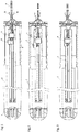
FIG. 1 is a schematic view of states of various parts when asliding block 3 is at an initial position; -
FIG. 2 is a schematic view of a state when acutter 4 is guided by the slidingblock 3 to enter a central track; -
FIG. 3 is a schematic view of a state when thesliding block 3 is not at the initial position; -
FIG. 4 is a schematic view of a guide surface and a locking projection of thecutter 4; -
FIG. 5 is a structural schematic view of a guide surface of thesliding block 3; -
FIG. 6 is a schematic view of a bias boss of astaple anvil 8; and -
FIG. 7 is a structural schematic view of a bias track and a blocking groove of thestaple cartridge base 2. - Technical solutions in the embodiments of the present disclosure will be described clearly and completely below in connection with the accompanying drawings of the description, and it will be apparent that the embodiments described are only some but not all embodiments of the present disclosure. All other embodiments obtained by those ordinarily skilled in the art based on the embodiments of the present disclosure without any creative efforts shall fall within the scope of protection of the present disclosure.
- The term "exemplary" is used herein to mean "serving as an example, instance, or illustration". Any implementation described herein as "exemplary" is not necessarily to be construed as being better than or superior to other implementations. Moreover, in the text, "proximal end", "proximal", and "rear" refer to an end proximate to an operator, and "distal end", "distal", and "front" refer to an end away from the operator.
- For the sake of simplicity, a stapler is taken as an example to illustrate the instrument of the present disclosure. Those skilled in the art could understand that a safety mechanism for ensuring disposable use of an instrument in the present disclosure is not limited to a stapler. In other products such as closures and electric scalpels, the technology of the present disclosure may also be adopted.
- For the safety mechanism for ensuring disposable use of a staple cartridge in a stapler in the present disclosure, the stapler includes an actuator located at a distal end, a controller located at a proximal end, and an extension tube located between the actuator and the controller. The extension tube is movably connected to a distal end of the controller, and a distal end of the extension tube is pivotably connected to a proximal end of the actuator, preferably by one or more hinges. The extension tube constitutes one connecting channel for transferring an action made by the controller to the actuator. The actuator includes a staple anvil assembly and a staple cartridge assembly that can clamp tissues therebetween.
- Specifically, the safety mechanism for ensuring disposable use of a staple cartridge in a stapler according to the present disclosure includes a
staple cartridge 1, astaple cartridge base 2, asliding block 3, acutter 4,protective plates 5 and 6, a cutter bar assembly 7, and astaple anvil 8, wherein thestaple cartridge base 2 is centrally provided with a central track, and the sliding block is provided on the staple cartridge base; with reference toFIG. 1 , thecutter 4 is fixedly connected at a distal end of the cutter bar assembly 7. - With reference to
FIG. 7 , a bias track is provided at a proximal end of thestaple cartridge base 2, marked as V inFIG. 7 , and the bias track is in communication with a proximal end of the central track of thestaple cartridge base 2. A blocking groove is provided at a distal end of the bias track, marked as V inFIG. 7 . - With reference to
FIG. 6 , a bias boss is provided at a proximal end of thestaple anvil 8, marked as IV inFIG. 6 , and the bias boss is corresponding to the bias track of thestaple cartridge base 2. - With reference to
FIG. 4 , a guide protrusion is provided on thecutter 4, marked as I inFIG. 4 ; and thecutter 4 is further provided with a locking projection, marked as II inFIG. 4 . - With reference to
FIG. 5 , thesliding block 3 is provided with a guide surface corresponding to the guide protrusion of thecutter 4, marked as III inFIG. 5 , and the guide surface is an inclined surface inclined in a direction from outside to a central axis of thestaple cartridge base 2, so that the guide protrusion can be guided from a biased position to a central position where the guide protrusion may move forwards, so that the guide protrusion may enter the central track. -
FIG. 1 is a structural schematic view of an embodiment of the present disclosure. The state in the figure is that thesliding block 3 is at an initial position. The slidingblock 3 is assembled at the proximal end of thestaple cartridge 1 before delivery, and when thestaple cartridge 1 is assembled into thestaple cartridge base 2, thesliding block 3 is positioned between the staple cartridge base and the staple cartridge, and located at the initial position, at the distal end of thecutter 4. At this time, the cutter bar assembly 7 is in contact with the bias boss (marked as IV inFIG. 6 ) at the proximal end of thestaple anvil 8, so that thecutter 4 is biased into the bias track of the staple cartridge base 2 (marked as V inFIG. 7 ), at this time, the guide protrusion (marked as I inFIG. 4 ) of thecutter 4 comes into contact with a proximal end of the guide surface (marked as III inFIG. 5 ) of thesliding block 3; when thecutter 4 and the cutter bar assembly 7 continue moving forward, the guide protrusion (marked as I inFIG. 4 ) of thecutter 4 enters the central track of the staple cartridge base under the guiding effect of the guide surface (marked as III inFIG. 5 ) of thesliding block 3, as inFIG. 2 , and at this time thecutter 4 may continue moving forwards. - When the
sliding block 3 is not at the initial position, as inFIG. 3 , thecutter 4 enters the bias track of thestaple cartridge base 2 due to restriction of the bias boss of thestaple anvil 8, and in this case, when thecutter 4 continues moving forwards without the restriction of the guide surface of thesliding block 3, the locking projection (marked as II inFIG. 4 ) of thecutter 4 enters the blocking groove (marked as V inFIG. 7 ) of thestaple cartridge base 2, and is restricted from moving forwards. - Specifically, the guide protrusion and the locking projection on the cutter are provided at two sides of the cutter in a horizontal direction (i.e. a direction perpendicular to a central axis of the stapler), respectively.
- The safety mechanism for ensuring disposable use of a staple cartridge in a stapler in the present disclosure has a simple and effective structure, and once the safety mechanism takes effect, it is difficult to destroy it by human force, thus ensuring the patients' safety in using the instrument.
- The above-mentioned are preferred embodiments of the present disclosure, and it should be indicated that those ordinarily skilled in the art still could make improvements and modifications, without departing from the principle of the present disclosure, and all of these improvements and modifications also should be considered as the scope of protection of the present disclosure.
Claims (12)
- A safety mechanism for ensuring disposable use of a staple cartridge in a stapler, comprising: the staple cartridge, a staple cartridge base, a sliding block, a cutter, and a staple anvil, wherein the staple cartridge base is centrally provided with a central track, a proximal end of the staple cartridge base is provided with a bias track, the bias track is in communication with a proximal end of the central track, a distal end of the bias track is provided with a blocking groove, and the sliding block is assembled at a proximal end of the staple cartridge; a first guide structure is provided on the cutter; the sliding block is provided with a second guide structure corresponding to the first guide structure of the cutter, and the second guide structure is capable of guiding the first guide structure to a central position from a biased position, so that the cutter enters the central track.
- The safety mechanism according to claim 1, wherein a third guide structure provided separated from the first guide structure is further provided on the cutter.
- The safety mechanism according to claim 2, wherein when the staple cartridge is assembled in the staple cartridge base, the sliding block is positioned between the staple cartridge base and the staple cartridge, and located in an initial position, and at a distal end of the cutter, and the first guide structure is in contact with the second guide structure.
- The safety mechanism according to claim 3, wherein a bias structure is provided at a proximal end of the staple anvil, the bias structure is corresponding to the bias track of the staple cartridge base, and the bias structure guides the cutter to enter the bias track of the staple cartridge base.
- The safety mechanism according to claim 4, wherein the bias structure is a bias boss.
- The safety mechanism according to any one of claims 1-5, wherein the cutter is fixedly connected at a distal end of a cutter bar assembly.
- The safety mechanism according to claim 4 or 5, wherein the first guide structure is a guide protrusion; and the second guide structure is a guide surface, and the third guide structure is a locking projection.
- The safety mechanism according to claim 7, wherein the guide surface is an inclined surface inclined in a direction from outside to a central axis of the staple cartridge base.
- The safety mechanism according to claim 7, wherein the guide protrusion and the locking projection are provided at two sides of the cutter in a horizontal direction, respectively.
- The safety mechanism according to claim 9, wherein at the initial position of the sliding block, the guide protrusion of the cutter is in contact with a proximal end of the guide surface of the sliding block; and when the cutter continues moving forward, the guide protrusion enters, under a guiding effect of the guide surface of the sliding block, the central track of the staple cartridge base.
- The safety mechanism according to claim 9, wherein when the sliding block is not at the initial position, the cutter enters the bias track of the staple cartridge base due to restriction of the bias structure of the staple anvil, and when the cutter continues moving forwards, the third guide structure enters the blocking groove of the staple cartridge base, and is restricted from moving forwards.
- Surgical instrument for ensuring disposable use of a staple cartridge, comprising: the staple cartridge, a staple cartridge base, a sliding block, a cutter, and a staple anvil, wherein the staple cartridge base is centrally provided with a central track, a proximal end of the staple cartridge base is provided with a bias track, the bias track is in communication with a proximal end of the central track, a distal end of the bias track is provided with a blocking groove, and the sliding block is assembled at a proximal end of the staple cartridge; a first guide structure is provided on the cutter; the sliding block is provided with a second guide structure corresponding to the first guide structure of the cutter, and the second guide structure is capable of guiding the first guide structure to a central position from a biased position, so that the cutter enters the central track.
Applications Claiming Priority (2)
| Application Number | Priority Date | Filing Date | Title |
|---|---|---|---|
| CN201811303644.2A CN111134752A (en) | 2018-11-02 | 2018-11-02 | An insurance agency that ensures that a device can only be used once |
| PCT/CN2019/114937 WO2020088629A1 (en) | 2018-11-02 | 2019-11-01 | Ensuring mechanism for ensuring device may only be used once |
Publications (4)
| Publication Number | Publication Date |
|---|---|
| EP3875040A1 true EP3875040A1 (en) | 2021-09-08 |
| EP3875040A4 EP3875040A4 (en) | 2022-08-24 |
| EP3875040B1 EP3875040B1 (en) | 2025-05-28 |
| EP3875040C0 EP3875040C0 (en) | 2025-05-28 |
Family
ID=70463828
Family Applications (1)
| Application Number | Title | Priority Date | Filing Date |
|---|---|---|---|
| EP19879588.2A Active EP3875040B1 (en) | 2018-11-02 | 2019-11-01 | Ensuring mechanism for ensuring device may only be used once |
Country Status (5)
| Country | Link |
|---|---|
| US (1) | US12433586B2 (en) |
| EP (1) | EP3875040B1 (en) |
| CN (1) | CN111134752A (en) |
| ES (1) | ES3036223T3 (en) |
| WO (1) | WO2020088629A1 (en) |
Cited By (1)
| Publication number | Priority date | Publication date | Assignee | Title |
|---|---|---|---|---|
| EP4520274A1 (en) * | 2023-09-07 | 2025-03-12 | Ezisurg Medical Co., Ltd. | Surgical stapler |
Families Citing this family (8)
| Publication number | Priority date | Publication date | Assignee | Title |
|---|---|---|---|---|
| CN111887920B (en) * | 2020-09-04 | 2025-05-06 | 北京派尔特医疗科技股份有限公司 | Stapler magazine and stapler |
| CN114246623B (en) | 2020-09-22 | 2026-01-09 | 上海逸思医疗科技股份有限公司 | End effector for anastomosis device |
| CN112472180B (en) * | 2020-12-17 | 2025-03-11 | 山东威瑞外科医用制品有限公司 | A laparoscopic stapler for preventing mis-activation |
| CN112472181B (en) * | 2020-12-22 | 2025-07-22 | 山东威瑞外科医用制品有限公司 | Cutting anastomat fast-assembling structure |
| CN113116439A (en) * | 2021-06-02 | 2021-07-16 | 上海博洽医疗器械有限公司 | Blocking mechanism of endoscopic surgical stapler |
| CN113288290B (en) * | 2021-07-07 | 2024-09-24 | 上海博洽医疗器械有限公司 | Nail magazine spacer for laparoscopic cutting stapler |
| WO2023138124A1 (en) * | 2022-01-20 | 2023-07-27 | 薛建新 | Actuating mechanism for everting stapling device, stapling device, and stapling device quality inspection method |
| CN118490291B (en) * | 2024-06-03 | 2025-11-21 | 苏州法兰克曼医疗器械有限公司 | Nail bin assembly and anastomat |
Family Cites Families (18)
| Publication number | Priority date | Publication date | Assignee | Title |
|---|---|---|---|---|
| US7334717B2 (en) | 2001-10-05 | 2008-02-26 | Tyco Healthcare Group Lp | Surgical fastener applying apparatus |
| US10159482B2 (en) | 2005-08-31 | 2018-12-25 | Ethicon Llc | Fastener cartridge assembly comprising a fixed anvil and different staple heights |
| US20070194079A1 (en) * | 2005-08-31 | 2007-08-23 | Hueil Joseph C | Surgical stapling device with staple drivers of different height |
| US7328828B2 (en) * | 2005-11-04 | 2008-02-12 | Ethicon Endo-Surgery, Inc, | Lockout mechanisms and surgical instruments including same |
| US9078653B2 (en) * | 2012-03-26 | 2015-07-14 | Ethicon Endo-Surgery, Inc. | Surgical stapling device with lockout system for preventing actuation in the absence of an installed staple cartridge |
| US9554796B2 (en) * | 2012-07-18 | 2017-01-31 | Covidien Lp | Multi-fire surgical stapling apparatus including safety lockout and visual indicator |
| CN102885641B (en) * | 2012-09-18 | 2015-04-01 | 上海逸思医疗科技有限公司 | Improved performer for surgical instruments |
| US9615825B2 (en) * | 2013-01-18 | 2017-04-11 | Covidien Lp | Release tool for an end effector of a surgical stapling apparatus |
| US9629628B2 (en) * | 2013-03-13 | 2017-04-25 | Covidien Lp | Surgical stapling apparatus |
| US9668728B2 (en) * | 2013-03-13 | 2017-06-06 | Covidien Lp | Surgical stapling apparatus |
| US9572577B2 (en) * | 2013-03-27 | 2017-02-21 | Ethicon Endo-Surgery, Llc | Fastener cartridge comprising a tissue thickness compensator including openings therein |
| CN105682570B (en) * | 2013-11-04 | 2019-02-01 | 柯惠Lp公司 | Surgical Fastener Applicator |
| US9681870B2 (en) * | 2013-12-23 | 2017-06-20 | Ethicon Llc | Articulatable surgical instruments with separate and distinct closing and firing systems |
| CN103767751B (en) | 2014-01-03 | 2016-02-24 | 上海逸思医疗科技有限公司 | A kind of surgical instruments of one-hand operation |
| CN105796145B (en) * | 2014-12-30 | 2018-10-30 | 苏州天臣国际医疗科技有限公司 | A kind of nail-head component and hysteroscope surgical operation seaming and cutting device |
| CN204708912U (en) * | 2015-03-13 | 2015-10-21 | 苏州天臣国际医疗科技有限公司 | Medical stapler |
| CN209951320U (en) * | 2018-11-02 | 2020-01-17 | 逸思(苏州)医疗科技有限公司 | Safety mechanism for ensuring that nail bin of anastomat can only be used once and surgical instrument |
| US11317915B2 (en) * | 2019-02-19 | 2022-05-03 | Cilag Gmbh International | Universal cartridge based key feature that unlocks multiple lockout arrangements in different surgical staplers |
-
2018
- 2018-11-02 CN CN201811303644.2A patent/CN111134752A/en active Pending
-
2019
- 2019-11-01 US US17/290,500 patent/US12433586B2/en active Active
- 2019-11-01 WO PCT/CN2019/114937 patent/WO2020088629A1/en not_active Ceased
- 2019-11-01 ES ES19879588T patent/ES3036223T3/en active Active
- 2019-11-01 EP EP19879588.2A patent/EP3875040B1/en active Active
Cited By (2)
| Publication number | Priority date | Publication date | Assignee | Title |
|---|---|---|---|---|
| EP4520274A1 (en) * | 2023-09-07 | 2025-03-12 | Ezisurg Medical Co., Ltd. | Surgical stapler |
| US12544071B2 (en) | 2023-09-07 | 2026-02-10 | Ezisurg Medical Co., Ltd. | Surgical stapler |
Also Published As
| Publication number | Publication date |
|---|---|
| EP3875040B1 (en) | 2025-05-28 |
| US12433586B2 (en) | 2025-10-07 |
| WO2020088629A1 (en) | 2020-05-07 |
| US20230181188A1 (en) | 2023-06-15 |
| ES3036223T3 (en) | 2025-09-16 |
| EP3875040A4 (en) | 2022-08-24 |
| EP3875040C0 (en) | 2025-05-28 |
| CN111134752A (en) | 2020-05-12 |
Similar Documents
| Publication | Publication Date | Title |
|---|---|---|
| EP3875040B1 (en) | Ensuring mechanism for ensuring device may only be used once | |
| US10702265B2 (en) | Surgical instrument including a locking assembly | |
| US10966716B2 (en) | Surgical stapler with articulation locking mechanism | |
| US10849622B2 (en) | Articulated stapling with fire lock | |
| US8808288B2 (en) | Surgical forceps including belt blade reverser mechanism | |
| US11826044B2 (en) | Surgical stapling device with curved tool assembly | |
| US20120323230A1 (en) | Laser fusion of tissue layers | |
| US11123072B2 (en) | Tissue closure device and medical instrument | |
| US20140276803A1 (en) | Electrosurgical instrument with a knife blade stop | |
| KR102705648B1 (en) | Launcher and stapler | |
| CN104688288A (en) | Medical stapler | |
| US20190046206A1 (en) | Surgical clip applier jaw alignment | |
| CN214387568U (en) | Endoscope cutting anastomat and nail box | |
| CN219480228U (en) | Clamping bin device and clip applier | |
| EP4669216A1 (en) | Clamping device with release mechanism | |
| WO2023197540A1 (en) | Gun-type electrotome with switchable sliding contact ring structure | |
| CN209951320U (en) | Safety mechanism for ensuring that nail bin of anastomat can only be used once and surgical instrument | |
| US12465358B2 (en) | End effector for surgical stapling device | |
| CN115153719A (en) | Hemostatic forceps | |
| CN106264714B (en) | A kind of high frequency electrosurgical surgical instrument and its driving device | |
| CN204797990U (en) | High frequency electric surgery surgical instruments and drive arrangement thereof | |
| CN107981904B (en) | A kind of tubal suturing forceps | |
| CN117100361A (en) | Side-entry separation forceps head and its application | |
| ES2798723T3 (en) | HF sealing instrument | |
| WO2021017989A1 (en) | Secondary firing-preventing safety apparatus for use in disposable endoscopic cutter stapler |
Legal Events
| Date | Code | Title | Description |
|---|---|---|---|
| STAA | Information on the status of an ep patent application or granted ep patent |
Free format text: STATUS: THE INTERNATIONAL PUBLICATION HAS BEEN MADE |
|
| PUAI | Public reference made under article 153(3) epc to a published international application that has entered the european phase |
Free format text: ORIGINAL CODE: 0009012 |
|
| STAA | Information on the status of an ep patent application or granted ep patent |
Free format text: STATUS: REQUEST FOR EXAMINATION WAS MADE |
|
| 17P | Request for examination filed |
Effective date: 20210521 |
|
| AK | Designated contracting states |
Kind code of ref document: A1 Designated state(s): AL AT BE BG CH CY CZ DE DK EE ES FI FR GB GR HR HU IE IS IT LI LT LU LV MC MK MT NL NO PL PT RO RS SE SI SK SM TR |
|
| DAV | Request for validation of the european patent (deleted) | ||
| DAX | Request for extension of the european patent (deleted) | ||
| A4 | Supplementary search report drawn up and despatched |
Effective date: 20220726 |
|
| RIC1 | Information provided on ipc code assigned before grant |
Ipc: A61B 17/072 20060101AFI20220720BHEP |
|
| GRAP | Despatch of communication of intention to grant a patent |
Free format text: ORIGINAL CODE: EPIDOSNIGR1 |
|
| STAA | Information on the status of an ep patent application or granted ep patent |
Free format text: STATUS: GRANT OF PATENT IS INTENDED |
|
| RIC1 | Information provided on ipc code assigned before grant |
Ipc: A61B 90/00 20160101ALI20241210BHEP Ipc: A61B 17/00 20060101ALI20241210BHEP Ipc: A61B 17/072 20060101AFI20241210BHEP |
|
| INTG | Intention to grant announced |
Effective date: 20241220 |
|
| GRAS | Grant fee paid |
Free format text: ORIGINAL CODE: EPIDOSNIGR3 |
|
| GRAA | (expected) grant |
Free format text: ORIGINAL CODE: 0009210 |
|
| STAA | Information on the status of an ep patent application or granted ep patent |
Free format text: STATUS: THE PATENT HAS BEEN GRANTED |
|
| AK | Designated contracting states |
Kind code of ref document: B1 Designated state(s): AL AT BE BG CH CY CZ DE DK EE ES FI FR GB GR HR HU IE IS IT LI LT LU LV MC MK MT NL NO PL PT RO RS SE SI SK SM TR |
|
| REG | Reference to a national code |
Ref country code: GB Ref legal event code: FG4D |
|
| REG | Reference to a national code |
Ref country code: CH Ref legal event code: EP |
|
| REG | Reference to a national code |
Ref country code: IE Ref legal event code: FG4D Ref country code: DE Ref legal event code: R096 Ref document number: 602019070629 Country of ref document: DE |
|
| U01 | Request for unitary effect filed |
Effective date: 20250627 |
|
| U07 | Unitary effect registered |
Designated state(s): AT BE BG DE DK EE FI FR IT LT LU LV MT NL PT RO SE SI Effective date: 20250723 |
|
| REG | Reference to a national code |
Ref country code: ES Ref legal event code: FG2A Ref document number: 3036223 Country of ref document: ES Kind code of ref document: T3 Effective date: 20250916 |
|
| PG25 | Lapsed in a contracting state [announced via postgrant information from national office to epo] |
Ref country code: NO Free format text: LAPSE BECAUSE OF FAILURE TO SUBMIT A TRANSLATION OF THE DESCRIPTION OR TO PAY THE FEE WITHIN THE PRESCRIBED TIME-LIMIT Effective date: 20250828 Ref country code: GR Free format text: LAPSE BECAUSE OF FAILURE TO SUBMIT A TRANSLATION OF THE DESCRIPTION OR TO PAY THE FEE WITHIN THE PRESCRIBED TIME-LIMIT Effective date: 20250829 |
|
| PG25 | Lapsed in a contracting state [announced via postgrant information from national office to epo] |
Ref country code: PL Free format text: LAPSE BECAUSE OF FAILURE TO SUBMIT A TRANSLATION OF THE DESCRIPTION OR TO PAY THE FEE WITHIN THE PRESCRIBED TIME-LIMIT Effective date: 20250528 |
|
| PG25 | Lapsed in a contracting state [announced via postgrant information from national office to epo] |
Ref country code: HR Free format text: LAPSE BECAUSE OF FAILURE TO SUBMIT A TRANSLATION OF THE DESCRIPTION OR TO PAY THE FEE WITHIN THE PRESCRIBED TIME-LIMIT Effective date: 20250528 |
|
| PG25 | Lapsed in a contracting state [announced via postgrant information from national office to epo] |
Ref country code: RS Free format text: LAPSE BECAUSE OF FAILURE TO SUBMIT A TRANSLATION OF THE DESCRIPTION OR TO PAY THE FEE WITHIN THE PRESCRIBED TIME-LIMIT Effective date: 20250828 |
|
| PG25 | Lapsed in a contracting state [announced via postgrant information from national office to epo] |
Ref country code: IS Free format text: LAPSE BECAUSE OF FAILURE TO SUBMIT A TRANSLATION OF THE DESCRIPTION OR TO PAY THE FEE WITHIN THE PRESCRIBED TIME-LIMIT Effective date: 20250928 |
|
| U20 | Renewal fee for the european patent with unitary effect paid |
Year of fee payment: 7 Effective date: 20251119 |
|
| PGFP | Annual fee paid to national office [announced via postgrant information from national office to epo] |
Ref country code: GB Payment date: 20251119 Year of fee payment: 7 |
|
| PG25 | Lapsed in a contracting state [announced via postgrant information from national office to epo] |
Ref country code: SM Free format text: LAPSE BECAUSE OF FAILURE TO SUBMIT A TRANSLATION OF THE DESCRIPTION OR TO PAY THE FEE WITHIN THE PRESCRIBED TIME-LIMIT Effective date: 20250528 |
|
| PG25 | Lapsed in a contracting state [announced via postgrant information from national office to epo] |
Ref country code: CZ Free format text: LAPSE BECAUSE OF FAILURE TO SUBMIT A TRANSLATION OF THE DESCRIPTION OR TO PAY THE FEE WITHIN THE PRESCRIBED TIME-LIMIT Effective date: 20250528 |
|
| PG25 | Lapsed in a contracting state [announced via postgrant information from national office to epo] |
Ref country code: SK Free format text: LAPSE BECAUSE OF FAILURE TO SUBMIT A TRANSLATION OF THE DESCRIPTION OR TO PAY THE FEE WITHIN THE PRESCRIBED TIME-LIMIT Effective date: 20250528 |
|
| PGFP | Annual fee paid to national office [announced via postgrant information from national office to epo] |
Ref country code: ES Payment date: 20251216 Year of fee payment: 7 |
|
| PLBE | No opposition filed within time limit |
Free format text: ORIGINAL CODE: 0009261 |
|
| STAA | Information on the status of an ep patent application or granted ep patent |
Free format text: STATUS: NO OPPOSITION FILED WITHIN TIME LIMIT |
|
| REG | Reference to a national code |
Ref country code: CH Ref legal event code: L10 Free format text: ST27 STATUS EVENT CODE: U-0-0-L10-L00 (AS PROVIDED BY THE NATIONAL OFFICE) Effective date: 20260409 |
|
| 26N | No opposition filed |
Effective date: 20260303 |
|
| REG | Reference to a national code |
Ref country code: CH Ref legal event code: H13 Free format text: ST27 STATUS EVENT CODE: U-0-0-H10-H13 (AS PROVIDED BY THE NATIONAL OFFICE) Effective date: 20260623 |
|
| PG25 | Lapsed in a contracting state [announced via postgrant information from national office to epo] |
Ref country code: MC Free format text: LAPSE BECAUSE OF FAILURE TO SUBMIT A TRANSLATION OF THE DESCRIPTION OR TO PAY THE FEE WITHIN THE PRESCRIBED TIME-LIMIT Effective date: 20250528 |
|
| PG25 | Lapsed in a contracting state [announced via postgrant information from national office to epo] |
Ref country code: CH Free format text: LAPSE BECAUSE OF NON-PAYMENT OF DUE FEES Effective date: 20251130 |