EP3875025A1 - Heart rate detection method, heart rate detection device and program - Google Patents
Heart rate detection method, heart rate detection device and program Download PDFInfo
- Publication number
- EP3875025A1 EP3875025A1 EP19880328.0A EP19880328A EP3875025A1 EP 3875025 A1 EP3875025 A1 EP 3875025A1 EP 19880328 A EP19880328 A EP 19880328A EP 3875025 A1 EP3875025 A1 EP 3875025A1
- Authority
- EP
- European Patent Office
- Prior art keywords
- time
- heartbeat
- max
- calculated
- heart rate
- Prior art date
- Legal status (The legal status is an assumption and is not a legal conclusion. Google has not performed a legal analysis and makes no representation as to the accuracy of the status listed.)
- Granted
Links
Images




Classifications
-
- A—HUMAN NECESSITIES
- A61—MEDICAL OR VETERINARY SCIENCE; HYGIENE
- A61B—DIAGNOSIS; SURGERY; IDENTIFICATION
- A61B5/00—Measuring for diagnostic purposes; Identification of persons
- A61B5/72—Signal processing specially adapted for physiological signals or for diagnostic purposes
- A61B5/7203—Signal processing specially adapted for physiological signals or for diagnostic purposes for noise prevention, reduction or removal
- A61B5/7207—Signal processing specially adapted for physiological signals or for diagnostic purposes for noise prevention, reduction or removal of noise induced by motion artifacts
-
- A—HUMAN NECESSITIES
- A61—MEDICAL OR VETERINARY SCIENCE; HYGIENE
- A61B—DIAGNOSIS; SURGERY; IDENTIFICATION
- A61B5/00—Measuring for diagnostic purposes; Identification of persons
- A61B5/24—Detecting, measuring or recording bioelectric or biomagnetic signals of the body or parts thereof
- A61B5/316—Modalities, i.e. specific diagnostic methods
- A61B5/318—Heart-related electrical modalities, e.g. electrocardiography [ECG]
- A61B5/346—Analysis of electrocardiograms
- A61B5/349—Detecting specific parameters of the electrocardiograph cycle
- A61B5/352—Detecting R peaks, e.g. for synchronising diagnostic apparatus; Estimating R-R interval
-
- A—HUMAN NECESSITIES
- A61—MEDICAL OR VETERINARY SCIENCE; HYGIENE
- A61B—DIAGNOSIS; SURGERY; IDENTIFICATION
- A61B5/00—Measuring for diagnostic purposes; Identification of persons
- A61B5/02—Detecting, measuring or recording for evaluating the cardiovascular system, e.g. pulse, heart rate, blood pressure or blood flow
- A61B5/024—Measuring pulse rate or heart rate
-
- A—HUMAN NECESSITIES
- A61—MEDICAL OR VETERINARY SCIENCE; HYGIENE
- A61B—DIAGNOSIS; SURGERY; IDENTIFICATION
- A61B5/00—Measuring for diagnostic purposes; Identification of persons
- A61B5/02—Detecting, measuring or recording for evaluating the cardiovascular system, e.g. pulse, heart rate, blood pressure or blood flow
- A61B5/024—Measuring pulse rate or heart rate
- A61B5/0245—Measuring pulse rate or heart rate by using sensing means generating electric signals, i.e. ECG signals
Definitions
- the present invention relates to a heartbeat detection method, heartbeat detection device, and program for detecting a heartbeat (R wave) from an electrocardiographic waveform.
- An ECG (Electrocardiogram) waveform is obtained by recording continuous electrical activities of a heart.
- a general ECG waveform is mainly formed from components called P, Q, R, S, and T waves representing the electrical activity statuses of right and left atriums and ventricles, as shown in Fig. 9 .
- Biological information such as a heart rate obtained from an ECG waveform is used as a representative index value indicating exercise intensity in a sport or the activity status of the autonomic function in daily life.
- a method of detecting a heartbeat from an ECG waveform As a method of detecting a heartbeat from an ECG waveform, a method of detecting the peak of an R wave having a relatively large amplitude from time-series data of the ECG waveform is easy. That is, with respect to the time-series data of the ECG waveform, a threshold is set in accordance with the amplitude of an R wave, an R wave is detected when a data value exceeds this threshold, and then an instantaneous heart rate is calculated from the period (patent literature 1).
- ECG waveform In measurement of an ECG waveform by a wearable device that is attracting attention in monitoring of biological information at normal time or during exercise, electrical noise caused by floating of an electrode, a body movement, or myoelectricity may be added to an ECG waveform.
- an abrupt variation in threshold is suppressed by setting, if large noise is superimposed on an ECG waveform, an upper limit for the above-described index value for R-wave detection, and not updating the threshold when the index value exceeds the upper limit, thereby detecting an R wave appropriately.
- the present invention has been made in consideration of the above problems, and has as its object to provide a heartbeat detection method, a heartbeat detection device, and a program which can accurately detect a heartbeat from an ECG waveform in which biological information other than a heartbeat represented by a body movement or myoelectricity is often mixed.
- a heartbeat detection method comprising a first step of calculating a heartbeat time from a sampling data string of an electrocardiographic waveform of a living body, a second step of calculating, for each heartbeat time, a heart rate from the heartbeat time calculated in the first step, and a third step of calculating, based on the heart rate calculated in the second step, a length of a skip period every time the heartbeat time is calculated, wherein the first step includes a step in which if a time difference between a latest time calculated from the sampling data string and an immediately preceding heartbeat time is not longer than the length of the skip period calculated from the immediately preceding heartbeat time, the latest time calculated from the sampling data string is not adopted as a heartbeat time.
- a heartbeat detection device comprising a heartbeat time calculation unit configured to calculate a heartbeat time from a sampling data string of an electrocardiographic waveform of a living body, a heart rate calculation unit configured to calculate, for each heartbeat time, a heart rate from the heartbeat time calculated by the heartbeat time calculation unit, and a skip period calculation unit configured to calculate, based on the heart rate calculated by the heart rate calculation unit, a length of a skip period every time the heartbeat time is calculated, wherein if a time difference between a latest time calculated from the sampling data string and an immediately preceding heartbeat time is not longer than the length of the skip period calculated from the immediately preceding heartbeat time, the heartbeat time calculation unit does not adopt, as a heartbeat time, the latest time calculated from the sampling data string.
- a heartbeat detection program causing a computer to execute a first step of calculating a heartbeat time from a sampling data string of an electrocardiographic waveform of a living body, a second step of calculating, for each heartbeat time, a heart rate from the heartbeat time calculated in the first step, and a third step of calculating, based on the heart rate calculated in the second step, a length of a skip period every time the heartbeat time is calculated, wherein the first step includes a step in which if a time difference between a latest time calculated from the sampling data string and an immediately preceding heartbeat time is not longer than the length of the skip period calculated from the immediately preceding heartbeat time, the latest time calculated from the sampling data string is not adopted as a heartbeat time.
- a heart rate is calculated, for each heartbeat time, from the calculated heartbeat time, and the length of a skip period is calculated based on the heart rate. If a time difference between the latest time calculated from a sampling data string and an immediately preceding heartbeat time is equal to or shorter than the length of the skip period calculated from the immediately preceding heartbeat time, the latest time calculated from the sampling data string is not adopted as a heartbeat time, thereby making it possible to accurately detect a heartbeat even from an electrocardiographic waveform in which information other than the heartbeat is often mixed.
- a heartbeat detection method calculates a heartbeat time from time-series data of an ECG waveform of a living body. However, by providing a period (skip period) during which the latest time calculated from the time-series data is not adopted as a heartbeat time based on a heart rate (R-R interval) detected from the time-series data of the ECG waveform, it is possible to prevent erroneous detection of noise during the period.
- the present invention variably sets a length t skip of a skip period in accordance with an instantaneous heart rate X [bpm] obtained from the latest R-R interval, as given by equation (1) below.
- t skip 60 Y X sec
- Y(X) [bpm] represents a variable corresponding to the value of the instantaneous heart rate X.
- variable Y(X) takes a value equal to or smaller than the upper limit (the R-R interval as the time interval between an R wave and an immediately preceding R wave) of the instantaneous heart rate X.
- n a natural number and ⁇ X is a constant.
- ⁇ X can experimentally be obtained in advance from the time-series data of the instantaneous heart rates X.
- Equation (5) may be used instead of equation (4).
- Y X ⁇ n + 1 X X ⁇ X max n + 1 n + r X X max n + 1 ⁇ X ⁇ X max n + r m + r X X max m + 1 + r ⁇ X ⁇ X max m + r X max X max 1 + r ⁇ X
- the variable Y(X) may be calculated by equation (6) below.
- Y X ⁇ 2 X + ⁇ X X + ⁇ X ⁇ X max 2 1 + r X + ⁇ X X max 2 ⁇ X + ⁇ X ⁇ X max 1 + r X max X max 1 + r ⁇ X + ⁇ X
- equation (7) below may be used instead of equation (6).
- Y X ⁇ n + 1 X + ⁇ X X + ⁇ X ⁇ X max n + 1 n + r X + ⁇ X X max n + 1 ⁇ X + ⁇ X ⁇ X max n + r n + r X + ⁇ X X max n + 1 ⁇ X + ⁇ X ⁇ X max n + r X max X max 1 + r ⁇ X + ⁇ X
- X in equations (2) to (8) need not always represent the instantaneous heart rate.
- X may represent an average heart rate calculated based on time-series data of the instantaneous heart rates.
- the skip period t skip during which no detection is performed (not adopted as a heartbeat time) when detecting a heartbeat, it is possible to prevent abnormal noise generated during the skip period t skip from being erroneously detected as a heartbeat.
- the heartbeat time in the present invention indicates a time at which a heartbeat of the heart of a living body is considered to occur.
- Fig. 1 is a block diagram showing the arrangement of a heartbeat detection device according to the embodiment of the present invention.
- Fig. 2 is a flowchart for explaining a heartbeat detection method according to the embodiment.
- the heartbeat detection device includes an electrocardiograph 1 that outputs a sampling data string of an ECG waveform, a storage unit 2 that stores the sampling data string of the ECG waveform and sampling time information, a heartbeat time calculation unit 3 that calculates a heartbeat time from the sampling data string of the ECG waveform, a heart rate calculation unit 4 that calculates, for each heartbeat time, a heart rate X from the heartbeat time calculated by the heartbeat time calculation unit 3, and a skip period calculation unit 5 that calculates, every time the heartbeat time is calculated, the length of a skip period t skip based on the heart rate X calculated by the heart rate calculation unit 4.
- the heartbeat detection method will be described below. A procedure of detecting one heartbeat and obtaining the heartbeat time thereof will be explained. This heartbeat time calculation processing is repeated for the period of ECG waveform data, thereby obtaining the time-series data of the heartbeat times.
- the electrocardiograph 1 measures the ECG waveform of a living body (human body) (not shown), and outputs the sampling data string D(i) of the ECG waveform. At this time, the electrocardiograph 1 adds sampling time information to each sampling data, and then outputs the sampling data string. Note that a practical measurement method of the ECG waveform is a well-known technique and a detailed description thereof will be omitted.
- the storage unit 2 stores the sampling data string D(i) of the ECG waveform and the sampling time information, which have been output from the electrocardiograph 1.
- the heartbeat time calculation unit 3 calculates the heartbeat time from the sampling data string D(i) of the ECG waveform stored in the storage unit 2 (step S1 of Fig. 2 ).
- Fig. 3 is a block diagram showing an example of the arrangement of the heartbeat time calculation unit 3.
- the heartbeat time calculation unit 3 is formed from an R-wave detection unit 30 that detects sampling data as a representative point of an R wave by comparing the sampling data D(i) of the ECG waveform with a first threshold TH for identifying an R wave, an S-wave detection unit 31 that detects sampling data as a representative point of an S wave by comparing the sampling data D(i) of the ECG waveform with a second threshold TL (TH > TL) for identifying an S wave, and a time calculation unit 32 that detects sampling data of two points sandwiching a third threshold TM (TH > TM > TL) between the representative point of the R wave and that of the S wave existing immediately after the point and calculates, as a heartbeat time, a time at which a straight line connecting the sampling data of the two points intersects the third threshold TM.
- TM third threshold
- the threshold TL for identifying the S wave is appropriately set to a value of about 60% to 70% of the potential of the typical S wave of the lead method adopted by the electrocardiograph 1
- the threshold TH for identifying the R wave is appropriately set to a value of about 60% to 70% of the potential of the typical R wave of the lead method adopted by the electrocardiograph 1.
- the threshold TM is preferentially set to a value near the intermediate value between the thresholds TL and TH.
- Fig. 4 is a block diagram showing another example of the arrangement of the heartbeat time calculation unit 3.
- the heartbeat time calculation unit 3 shown in Fig. 4 is formed from a time difference value calculation unit 33 that calculates, for each sampling time, the time difference value of the sampling data D(i) of the ECG waveform, a time difference value determination unit 34 that determines whether the time difference value is smaller than the threshold TH2, a time determination unit 35 that determines whether the first elapsed time from the immediately preceding heartbeat time to the latest sampling time at which the time difference value is obtained falls within the range of the first time interval, whether the second elapsed time from a time at which the time difference value becomes smaller than the threshold TH2 to the latest sampling time at which the time difference value is obtained falls within the range of the second time interval, and whether the third elapsed time from a time at which it is determined that the second elapsed time exceeds the range of the second time interval to the latest sampling time at which the time difference value is obtained falls within the range of the third time
- the time difference value determination unit 34 determines whether the time difference value DY(i) is smaller than the threshold TH2. Since the peak of the time difference value DY(i) by an abrupt change from an R wave to an S wave is to be detected, this peak appears as a negative value. Therefore, the threshold TH2 is a negative value.
- the first time interval defines a time domain before the assumed next heartbeat time
- the second time interval defines a time domain assumed to include the peak of the time difference value DY(i)
- the third time interval defines a predetermined time domain after the time domain assumed to include the peak of the time difference value DY(i).
- the time determination unit 35 sets, as the range of the first time interval, an interval from a time 150 ms shorter than an R-R interval obtained from the immediately preceding heartbeat time to a time obtained by adding 100 ms to the time.
- the R-R interval indicates a time obtained by subtracting the second preceding heartbeat time from the immediately preceding heartbeat time.
- the time determination unit 35 sets, as the range of the first time interval, the time domain from the immediately preceding heartbeat time to a time immediately before the time difference value DY(i) exceeds the threshold TH2 next.
- the second time interval preferably has a time width enough to cover the peak of the time difference value, and is preset to, for example, 50 ms.
- the third time interval is preset to, for example, 100 ms.
- a condition that a ratio Min2/Min1 of the minimum value Min2 to the minimum value Min1 and a ratio Min2/Min3 of the minimum value Min2 to the minimum value Min3 exceed a predetermined value is set as the heartbeat time confirmation condition.
- Fig. 5 is a block diagram showing still another example of the arrangement of the heartbeat time calculation unit 3.
- the heartbeat time calculation unit 3 shown in Fig. 5 is formed from a time difference value calculation unit 40 that calculates, for each sampling time, the time difference value DY(i) of the sampling data D(i) of the ECG waveform, a minimum value acquisition unit 41 that acquires, for each sampling point i, the minimum value of the time difference values in the predetermined time domains before and after the sampling point, an index value calculation unit 42 that obtains, for each sampling point i, as an index value, a value by subtracting the minimum value of the time difference values in the predetermined time domains before and after the sampling point i from the time difference value DY(i) of the sampling point i, and a time decision unit 43 that specifies, as a downward peak, from index values for the sampling points i, the index value of a point at which the index value becomes smaller than the predetermined threshold and the tendency of a change in index value changes from decrease to increase, and
- the predetermined time domains before and after the sampling point i are, for example, a domain of -112.5 ms to -12.5 ms and a domain of +12.5 ms to +112.5 ms with respect to the time of the sampling point i.
- the heartbeat time calculation unit 3 determines whether the time calculated in step S1 is appropriate, and confirms a heartbeat time. More specifically, the heartbeat time calculation unit 3 determines whether a time difference ⁇ T between the latest time calculated in step S1 and an immediately precedingly calculated/confirmed heartbeat time is longer than the length t skip of the skip period immediately precedingly calculated by the skip period calculation unit 5 (step S2 of Fig. 2 ). If the time difference ⁇ T is equal to or shorter than the length t skip of the skip period (NO in step S2), the time calculated in step S1 is discarded without being adopted as a heartbeat time. In this case, the processing target is advanced to the sampling data D(i) of the next sampling time, and the processes in step S1 and the subsequent steps are performed again.
- the heartbeat time calculation unit 3 determines the time calculated in step S1 as a heartbeat time (step S3 of Fig. 2 ).
- the heart rate calculation unit 4 calculates the heart rate X [bpm] from the latest heartbeat time calculated/confirmed by the heartbeat time calculation unit 3 (step S4 of Fig. 2 ).
- the heart rate calculation unit 4 may calculate the average heart rate X by equation (9), instead of the instantaneous heart rate.
- the skip period calculation unit 5 calculates the length t skip of the skip period by equation (1) and one of equations (2) to (8) based on the heart rate X (instantaneous heart rate or average heart rate) calculated by the heart rate calculation unit 4 (step S5 of Fig. 2 ). Note that the calculated length t skip of the skip period is used when the processing in step S2 is performed next.
- the time-series data of the heartbeat times are obtained by repeating the processes in step S1 to S5.
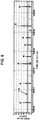
- Fig. 6 shows the time-series data of index values (index values calculated by the index value calculation unit 42 of Fig. 5 ) calculated by the method disclosed in patent literature 3 from the time-series data of the ECG waveform. Note that a value obtained by subtracting the time difference value DY(i) of the sampling point i from the minimum value of the time difference values in the predetermined time domains before and after the sampling point i is set as an index value.
- R represents an R wave and N represents noise other than the R waves.
- N represents noise other than the R waves.
- two large noise components (N) appear in the index values between the third and fifth R waves, and the two noise components exceed a threshold TH3.
- the times of the two noise components are erroneously calculated as heartbeat times.
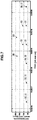
- Fig. 7 shows the instantaneous heart rates calculated by the conventional heartbeat detection method disclosed in patent literature 4 and by this embodiment based on the time-series data of the same ECG waveform as in Fig. 6 .
- X0 represents the instantaneous heart rate calculated by the conventional heartbeat detection method
- X1 represents the instantaneous heart rate calculated by this embodiment.
- n is set to 1 (equation (2))
- ⁇ X is set to 15 bpm
- r is set to 1/3
- X max is set to 250 bpm with reference to patent literature 3.
- the instantaneous heart rate changes irregularly.
- the instantaneous heart rate is stable, and it is thus understood that erroneous calculation of the instantaneous heart rate caused by noise can be prevented.
- the storage unit 2, heartbeat time calculation unit 3, heart rate calculation unit 4, and skip period calculation unit 5 of the heartbeat detection device described in this embodiment can be implemented by a computer including a CPU (Central Processing Unit), a storage device, and an interface, and a program for controlling these hardware resources.
- Fig. 8 shows an example of the arrangement of this computer.
- the computer includes a CPU 100, a storage device 101, and an interface device (to be referred to as an I/F hereinafter) 102.
- the I/F 102 is connected to the electrocardiograph 1 and the like.
- a heartbeat detection program for implementing the heartbeat detection method of the present invention is provided while being recorded on a recording medium such as a flexible disk, CD-ROM, DVD-ROM, or memory card, and stored in the storage device 101.
- the CPU 100 executes the processing described in this embodiment in accordance with the program stored in the storage device 101.
- the present invention is applicable to a technique of detecting a heartbeat of a living body.
Landscapes
- Health & Medical Sciences (AREA)
- Life Sciences & Earth Sciences (AREA)
- Cardiology (AREA)
- Engineering & Computer Science (AREA)
- Molecular Biology (AREA)
- General Health & Medical Sciences (AREA)
- Biophysics (AREA)
- Biomedical Technology (AREA)
- Heart & Thoracic Surgery (AREA)
- Medical Informatics (AREA)
- Physics & Mathematics (AREA)
- Surgery (AREA)
- Animal Behavior & Ethology (AREA)
- Pathology (AREA)
- Public Health (AREA)
- Veterinary Medicine (AREA)
- Physiology (AREA)
- Signal Processing (AREA)
- Artificial Intelligence (AREA)
- Computer Vision & Pattern Recognition (AREA)
- Psychiatry (AREA)
- Measurement And Recording Of Electrical Phenomena And Electrical Characteristics Of The Living Body (AREA)
- Measuring Pulse, Heart Rate, Blood Pressure Or Blood Flow (AREA)
Abstract
Description
- The present invention relates to a heartbeat detection method, heartbeat detection device, and program for detecting a heartbeat (R wave) from an electrocardiographic waveform.
- An ECG (Electrocardiogram) waveform is obtained by recording continuous electrical activities of a heart. A general ECG waveform is mainly formed from components called P, Q, R, S, and T waves representing the electrical activity statuses of right and left atriums and ventricles, as shown in
Fig. 9 . Biological information such as a heart rate obtained from an ECG waveform is used as a representative index value indicating exercise intensity in a sport or the activity status of the autonomic function in daily life. - As a method of detecting a heartbeat from an ECG waveform, a method of detecting the peak of an R wave having a relatively large amplitude from time-series data of the ECG waveform is easy. That is, with respect to the time-series data of the ECG waveform, a threshold is set in accordance with the amplitude of an R wave, an R wave is detected when a data value exceeds this threshold, and then an instantaneous heart rate is calculated from the period (patent literature 1).
- To reduce undulation in a baseline of an ECG waveform caused by a body movement or the like, there are proposed a method (patent literature 2) that uses the time difference of the waveform as an index value instead of using the time-series data of the waveform, and a method (patent literature 3) that uses, as a new index, a value considering clearances before and after the peak from the time difference by paying attention to small individual differences of the peak widths between the Q, R, and S waves, thereby making it possible to detect an R wave more accurately.
- In measurement of an ECG waveform by a wearable device that is attracting attention in monitoring of biological information at normal time or during exercise, electrical noise caused by floating of an electrode, a body movement, or myoelectricity may be added to an ECG waveform.
- To cope with this, in a heartbeat detection method disclosed in patent literature 4, an abrupt variation in threshold is suppressed by setting, if large noise is superimposed on an ECG waveform, an upper limit for the above-described index value for R-wave detection, and not updating the threshold when the index value exceeds the upper limit, thereby detecting an R wave appropriately.
- However, in the method disclosed in patent literature 4, if noise having an equal amplitude occurs between R waves, this noise is erroneously detected as an R wave, and a heart rate is thus erroneously detected as a value higher than an actual value.
-
- Patent Literature 1:
Japanese Patent Laid-Open No. 2015-156936 - Patent Literature 2:
Japanese Patent Laid-Open No. 2017-29628 - Patent Literature 3:
Japanese Patent Laid-Open No. 2017-42388 - Patent Literature 4:
Japanese Patent Laid-Open No. 2017-150156 - The present invention has been made in consideration of the above problems, and has as its object to provide a heartbeat detection method, a heartbeat detection device, and a program which can accurately detect a heartbeat from an ECG waveform in which biological information other than a heartbeat represented by a body movement or myoelectricity is often mixed.
- According to the present invention, there is provided a heartbeat detection method comprising a first step of calculating a heartbeat time from a sampling data string of an electrocardiographic waveform of a living body, a second step of calculating, for each heartbeat time, a heart rate from the heartbeat time calculated in the first step, and a third step of calculating, based on the heart rate calculated in the second step, a length of a skip period every time the heartbeat time is calculated, wherein the first step includes a step in which if a time difference between a latest time calculated from the sampling data string and an immediately preceding heartbeat time is not longer than the length of the skip period calculated from the immediately preceding heartbeat time, the latest time calculated from the sampling data string is not adopted as a heartbeat time.
- According to the present invention, there is also provided a heartbeat detection device comprising a heartbeat time calculation unit configured to calculate a heartbeat time from a sampling data string of an electrocardiographic waveform of a living body, a heart rate calculation unit configured to calculate, for each heartbeat time, a heart rate from the heartbeat time calculated by the heartbeat time calculation unit, and a skip period calculation unit configured to calculate, based on the heart rate calculated by the heart rate calculation unit, a length of a skip period every time the heartbeat time is calculated, wherein if a time difference between a latest time calculated from the sampling data string and an immediately preceding heartbeat time is not longer than the length of the skip period calculated from the immediately preceding heartbeat time, the heartbeat time calculation unit does not adopt, as a heartbeat time, the latest time calculated from the sampling data string.
- According to the present invention, there is also provided a heartbeat detection program causing a computer to execute a first step of calculating a heartbeat time from a sampling data string of an electrocardiographic waveform of a living body, a second step of calculating, for each heartbeat time, a heart rate from the heartbeat time calculated in the first step, and a third step of calculating, based on the heart rate calculated in the second step, a length of a skip period every time the heartbeat time is calculated, wherein the first step includes a step in which if a time difference between a latest time calculated from the sampling data string and an immediately preceding heartbeat time is not longer than the length of the skip period calculated from the immediately preceding heartbeat time, the latest time calculated from the sampling data string is not adopted as a heartbeat time.
- According to the present invention, a heart rate is calculated, for each heartbeat time, from the calculated heartbeat time, and the length of a skip period is calculated based on the heart rate. If a time difference between the latest time calculated from a sampling data string and an immediately preceding heartbeat time is equal to or shorter than the length of the skip period calculated from the immediately preceding heartbeat time, the latest time calculated from the sampling data string is not adopted as a heartbeat time, thereby making it possible to accurately detect a heartbeat even from an electrocardiographic waveform in which information other than the heartbeat is often mixed.
-
-
Fig. 1 is a block diagram showing the arrangement of a heartbeat detection device according to an embodiment of the present invention; -
Fig. 2 is a flowchart for explaining a heartbeat detection method according to the embodiment of the present invention; -
Fig. 3 is a block diagram showing an example of the arrangement of a heartbeat time calculation unit of the heartbeat detection device according to the embodiment of the present invention; -
Fig. 4 is a block diagram showing another example of the arrangement of the heartbeat time calculation unit of the heartbeat detection device according to the embodiment of the present invention; -
Fig. 5 is a block diagram showing still another example of the arrangement of the heartbeat time calculation unit of the heartbeat detection device according to the embodiment of the present invention; -
Fig. 6 is a timing chart showing time-series data of index values calculated by a conventional heartbeat detection method; -
Fig. 7 is a timing chart showing instantaneous heart rates calculated by the conventional heartbeat detection method and the heartbeat detection method according to the embodiment of the present invention; -
Fig. 8 is a block diagram showing an example of the arrangement of a computer for implementing the heartbeat detection device according to the embodiment of the present invention; and -
Fig. 9 is a timing chart showing a representative electrocardiographic waveform. - A heartbeat detection method according to the present invention calculates a heartbeat time from time-series data of an ECG waveform of a living body. However, by providing a period (skip period) during which the latest time calculated from the time-series data is not adopted as a heartbeat time based on a heart rate (R-R interval) detected from the time-series data of the ECG waveform, it is possible to prevent erroneous detection of noise during the period.
- More specifically, while the conventional method detects no R wave during a period corresponding to an R-R interval corresponding to the upper limit of a detected heart rate after detection of a heartbeat, the present invention variably sets a length tskip of a skip period in accordance with an instantaneous heart rate X [bpm] obtained from the latest R-R interval, as given by equation (1) below.

where Y(X) [bpm] represents a variable corresponding to the value of the instantaneous heart rate X. In consideration of prevention of detection of an abnormal value exceeding the upper limit value of the heart rate, the variable Y(X) takes a value equal to or smaller than the upper limit (the R-R interval as the time interval between an R wave and an immediately preceding R wave) of the instantaneous heart rate X. In consideration of missing an R wave (n-1) times (n is a natural number), the variable Y(X) is calculated by:
- In consideration of a variation component ΔX of the instantaneous heart rate X caused by a variation in appearance interval of an R wave, the variable Y(X) may be calculated by:

- In equation (3), n represents a natural number and ΔX is a constant. For example, ΔX can experimentally be obtained in advance from the time-series data of the instantaneous heart rates X.
- In consideration of a possible upper limit value Xmax of the heart rate X, the variable Y(X) may be calculated by equation (4) below.


- In equation (5), n represents an integer of 2 or more, and m takes each integer from (n-1) to 1. For example, m = 3, 2, 1 is obtained for n = 4. Equation (5) means that Y (X) = (n + 1)X for X ≤ Xmax/(n + 1), Y(X) = (n + r) X for Xmax/ (n + 1) < X ≤ Xmax/(n + r), Y (X) = (m + r) X for Xmax/ (m + 1 + r) < X ≤ Xmax/ (m + r), and Y (X) = Xmax for X > Xmax/ (1 + r). Equation (5) is an equation obtained when considering missing of n R waves, and Equation (4) corresponds to a case in which n = 1 set in equation (5). In consideration of missing of R waves, the variation component ΔX of the heart rate X, and the upper limit value Xmax of the heart rate X, the variable Y(X) may be calculated by equation (6) below.

- Equation (6) means that Y(X) = 2(X + ΔX) for X + ΔX ≤ Xmax/2, Y (X) = (1 + r) (X + ΔX) for
X max/2 < X + ΔX ≤ Xmax/ (1 + r), and Y (X) = Xmax for X + ΔX > Xmax/ (1 + r) . Note that equation (7) below may be used instead of equation (6).
- In equation (7), n represents an integer of 2 or more. Equation (7) means that Y(X) = (n + 1)(X + ΔX) for X + ΔX ≤ Xmax/(n + 1), Y (X) = (n + r) (X + ΔX) for Xmax/(n + 1) < X + ΔX ≤ Xmax/(n + r), Y (X) = (m + r) (X + ΔX) for Xmax/ (m + 1 + r) < X + ΔX ≤ Xmax/ (m + r), and Y (X) = Xmax for X + ΔX > Xmax/(1 + r). Equation (7) is an equation obtained when considering missing of n R waves, and equation (6) corresponds to a case in which n = 1 is set in equation (7).
- Note that if the variation component ΔX of the heart rate X and the upper limit value Xmax of the heart rate X are considered without considering missing of R waves, the following equation is obtained.

- Equation (8) means that Y(X) = X + ΔX for X + ΔX ≤ Xmax, and Y (X) = Xmax for X + ΔX > Xmax.
- X in equations (2) to (8) need not always represent the instantaneous heart rate. As disclosed in
Japanese Patent Laid-Open No. 2018-011819 - According to
Japanese Patent Laid-Open No. 2018-011819 
- As described above, according to the present invention, by variably setting, for each heartbeat detection operation, the skip period tskip during which no detection is performed (not adopted as a heartbeat time) when detecting a heartbeat, it is possible to prevent abnormal noise generated during the skip period tskip from being erroneously detected as a heartbeat.
- Note that the heartbeat time in the present invention indicates a time at which a heartbeat of the heart of a living body is considered to occur.
- An embodiment of the present invention will be described below with reference to the accompanying drawings.
Fig. 1 is a block diagram showing the arrangement of a heartbeat detection device according to the embodiment of the present invention.Fig. 2 is a flowchart for explaining a heartbeat detection method according to the embodiment. The heartbeat detection device includes anelectrocardiograph 1 that outputs a sampling data string of an ECG waveform, astorage unit 2 that stores the sampling data string of the ECG waveform and sampling time information, a heartbeattime calculation unit 3 that calculates a heartbeat time from the sampling data string of the ECG waveform, a heart rate calculation unit 4 that calculates, for each heartbeat time, a heart rate X from the heartbeat time calculated by the heartbeattime calculation unit 3, and a skipperiod calculation unit 5 that calculates, every time the heartbeat time is calculated, the length of a skip period tskip based on the heart rate X calculated by the heart rate calculation unit 4. - The heartbeat detection method according to this embodiment will be described below. A procedure of detecting one heartbeat and obtaining the heartbeat time thereof will be explained. This heartbeat time calculation processing is repeated for the period of ECG waveform data, thereby obtaining the time-series data of the heartbeat times.
- In this embodiment, a data string obtained by sampling an ECG waveform is represented by D(i) where i (i = 1, 2,...) is a number added to one sampling data. As the number i is larger, the sampling time is later, as a matter of course.
- The
electrocardiograph 1 measures the ECG waveform of a living body (human body) (not shown), and outputs the sampling data string D(i) of the ECG waveform. At this time, theelectrocardiograph 1 adds sampling time information to each sampling data, and then outputs the sampling data string. Note that a practical measurement method of the ECG waveform is a well-known technique and a detailed description thereof will be omitted. - The
storage unit 2 stores the sampling data string D(i) of the ECG waveform and the sampling time information, which have been output from theelectrocardiograph 1. - Next, the heartbeat
time calculation unit 3 calculates the heartbeat time from the sampling data string D(i) of the ECG waveform stored in the storage unit 2 (step S1 ofFig. 2 ). -
Fig. 3 is a block diagram showing an example of the arrangement of the heartbeattime calculation unit 3. The heartbeattime calculation unit 3 is formed from an R-wave detection unit 30 that detects sampling data as a representative point of an R wave by comparing the sampling data D(i) of the ECG waveform with a first threshold TH for identifying an R wave, an S-wave detection unit 31 that detects sampling data as a representative point of an S wave by comparing the sampling data D(i) of the ECG waveform with a second threshold TL (TH > TL) for identifying an S wave, and atime calculation unit 32 that detects sampling data of two points sandwiching a third threshold TM (TH > TM > TL) between the representative point of the R wave and that of the S wave existing immediately after the point and calculates, as a heartbeat time, a time at which a straight line connecting the sampling data of the two points intersects the third threshold TM. - Since the potential of the S or R wave changes depending on an ECG lead method, the threshold TL for identifying the S wave is appropriately set to a value of about 60% to 70% of the potential of the typical S wave of the lead method adopted by the
electrocardiograph 1, and the threshold TH for identifying the R wave is appropriately set to a value of about 60% to 70% of the potential of the typical R wave of the lead method adopted by theelectrocardiograph 1. The threshold TM is preferentially set to a value near the intermediate value between the thresholds TL and TH. - The arrangement of the heartbeat
time calculation unit 3 shown inFig. 3 is disclosed inpatent literature 1 and a detailed description thereof will be omitted. -
Fig. 4 is a block diagram showing another example of the arrangement of the heartbeattime calculation unit 3. The heartbeat time calculation unit 3 shown inFig. 4 is formed from a time difference value calculation unit 33 that calculates, for each sampling time, the time difference value of the sampling data D(i) of the ECG waveform, a time difference value determination unit 34 that determines whether the time difference value is smaller than the threshold TH2, a time determination unit 35 that determines whether the first elapsed time from the immediately preceding heartbeat time to the latest sampling time at which the time difference value is obtained falls within the range of the first time interval, whether the second elapsed time from a time at which the time difference value becomes smaller than the threshold TH2 to the latest sampling time at which the time difference value is obtained falls within the range of the second time interval, and whether the third elapsed time from a time at which it is determined that the second elapsed time exceeds the range of the second time interval to the latest sampling time at which the time difference value is obtained falls within the range of the third time interval, a minimum value holding unit 36 that holds a minimum value Min1 of the time difference values when the first elapsed time falls within the range of the first time interval, a minimum value Min2 of the time difference values when the second elapsed time falls within the range of the second time interval, and a minimum value Min3 of the time difference values when the third elapsed time falls within the range of the third time interval, and a time decision unit 37 that sets, if the relationship among the minimum values Min1, Min2, and Min3 satisfies a predetermined heartbeat time confirmation condition, as a heartbeat time, a time at which the time difference value becomes smaller than the threshold TH2 or the minimum value Min2 is obtained. - The time difference
value calculation unit 33 acquires, from thestorage unit 2, data D(i+1) one sampling operation after the sampling data D(i) and data D(i-1) one sampling operation before the sampling data D(i), and calculates a time difference value DY(i) of the sampling data D(i), as given by:
- The time difference
value determination unit 34 determines whether the time difference value DY(i) is smaller than the threshold TH2. Since the peak of the time difference value DY(i) by an abrupt change from an R wave to an S wave is to be detected, this peak appears as a negative value. Therefore, the threshold TH2 is a negative value. The first time interval defines a time domain before the assumed next heartbeat time, the second time interval defines a time domain assumed to include the peak of the time difference value DY(i), and the third time interval defines a predetermined time domain after the time domain assumed to include the peak of the time difference value DY(i). - The
time determination unit 35 sets, as the range of the first time interval, an interval from a time 150 ms shorter than an R-R interval obtained from the immediately preceding heartbeat time to a time obtained by adding 100 ms to the time. The R-R interval indicates a time obtained by subtracting the second preceding heartbeat time from the immediately preceding heartbeat time. Alternatively, thetime determination unit 35 sets, as the range of the first time interval, the time domain from the immediately preceding heartbeat time to a time immediately before the time difference value DY(i) exceeds the threshold TH2 next. The second time interval preferably has a time width enough to cover the peak of the time difference value, and is preset to, for example, 50 ms. The third time interval is preset to, for example, 100 ms. - Furthermore, a condition that a ratio Min2/Min1 of the minimum value Min2 to the minimum value Min1 and a ratio Min2/Min3 of the minimum value Min2 to the minimum value Min3 exceed a predetermined value is set as the heartbeat time confirmation condition.
- The arrangement of the heartbeat
time calculation unit 3 shown inFig. 4 is disclosed inpatent literature 2 and a detailed description thereof will be omitted. -
Fig. 5 is a block diagram showing still another example of the arrangement of the heartbeattime calculation unit 3. The heartbeattime calculation unit 3 shown inFig. 5 is formed from a time differencevalue calculation unit 40 that calculates, for each sampling time, the time difference value DY(i) of the sampling data D(i) of the ECG waveform, a minimumvalue acquisition unit 41 that acquires, for each sampling point i, the minimum value of the time difference values in the predetermined time domains before and after the sampling point, an indexvalue calculation unit 42 that obtains, for each sampling point i, as an index value, a value by subtracting the minimum value of the time difference values in the predetermined time domains before and after the sampling point i from the time difference value DY(i) of the sampling point i, and atime decision unit 43 that specifies, as a downward peak, from index values for the sampling points i, the index value of a point at which the index value becomes smaller than the predetermined threshold and the tendency of a change in index value changes from decrease to increase, and sets the time of the specified downward peak as a heartbeat time. - The predetermined time domains before and after the sampling point i are, for example, a domain of -112.5 ms to -12.5 ms and a domain of +12.5 ms to +112.5 ms with respect to the time of the sampling point i.
- The arrangement of the heartbeat
time calculation unit 3 shown inFig. 5 is disclosed inpatent literatures 3 and 4, and a detailed description thereof will be omitted. - Subsequently, the heartbeat
time calculation unit 3 determines whether the time calculated in step S1 is appropriate, and confirms a heartbeat time. More specifically, the heartbeattime calculation unit 3 determines whether a time difference ΔT between the latest time calculated in step S1 and an immediately precedingly calculated/confirmed heartbeat time is longer than the length tskip of the skip period immediately precedingly calculated by the skip period calculation unit 5 (step S2 ofFig. 2 ). If the time difference ΔT is equal to or shorter than the length tskip of the skip period (NO in step S2), the time calculated in step S1 is discarded without being adopted as a heartbeat time. In this case, the processing target is advanced to the sampling data D(i) of the next sampling time, and the processes in step S1 and the subsequent steps are performed again. - Furthermore, if the time difference ΔT is longer than the length tskip of the skip period (YES in step S2), the heartbeat
time calculation unit 3 determines the time calculated in step S1 as a heartbeat time (step S3 ofFig. 2 ). - Next, the heart rate calculation unit 4 calculates the heart rate X [bpm] from the latest heartbeat time calculated/confirmed by the heartbeat time calculation unit 3 (step S4 of
Fig. 2 ). When the R-R interval as the time obtained by subtracting the immediately preceding heartbeat time from the latest heartbeat time calculated/confirmed by the heartbeattime calculation unit 3 is represented by RRI [ms], the heart rate calculation unit 4 calculates the instantaneous heart rate X by:
- The heart rate calculation unit 4 may calculate the average heart rate X by equation (9), instead of the instantaneous heart rate.
- Subsequently, the skip
period calculation unit 5 calculates the length tskip of the skip period by equation (1) and one of equations (2) to (8) based on the heart rate X (instantaneous heart rate or average heart rate) calculated by the heart rate calculation unit 4 (step S5 ofFig. 2 ). Note that the calculated length tskip of the skip period is used when the processing in step S2 is performed next. - The time-series data of the heartbeat times are obtained by repeating the processes in step S1 to S5.
-
Fig. 6 shows the time-series data of index values (index values calculated by the indexvalue calculation unit 42 ofFig. 5 ) calculated by the method disclosed inpatent literature 3 from the time-series data of the ECG waveform. Note that a value obtained by subtracting the time difference value DY(i) of the sampling point i from the minimum value of the time difference values in the predetermined time domains before and after the sampling point i is set as an index value. InFig. 6 , R represents an R wave and N represents noise other than the R waves. In the example shown inFig. 6 , two large noise components (N) appear in the index values between the third and fifth R waves, and the two noise components exceed a threshold TH3. Thus, it is understood that the times of the two noise components are erroneously calculated as heartbeat times. -
Fig. 7 shows the instantaneous heart rates calculated by the conventional heartbeat detection method disclosed in patent literature 4 and by this embodiment based on the time-series data of the same ECG waveform as inFig. 6 . InFig. 7 , X0 represents the instantaneous heart rate calculated by the conventional heartbeat detection method and X1 represents the instantaneous heart rate calculated by this embodiment. In this embodiment, n is set to 1 (equation (2)), ΔX is set to 15 bpm, r is set to 1/3, and Xmax is set to 250 bpm with reference topatent literature 3. In the conventional heartbeat detection method, since the time of noise is also detected as a heartbeat time, the instantaneous heart rate changes irregularly. On the other hand, in this embodiment, the instantaneous heart rate is stable, and it is thus understood that erroneous calculation of the instantaneous heart rate caused by noise can be prevented. - As described above, according to this embodiment, it is demonstrated that it is possible to accurately detect a heartbeat even from an ECG waveform in which information other than the heartbeat (R wave) is often mixed.
- Note that in this embodiment, the methods disclosed in
patent literature 1 to 4 are each used as the heartbeat time calculation method. The present invention, however, is applicable regardless of the heartbeat time calculation method. - The
storage unit 2, heartbeattime calculation unit 3, heart rate calculation unit 4, and skipperiod calculation unit 5 of the heartbeat detection device described in this embodiment can be implemented by a computer including a CPU (Central Processing Unit), a storage device, and an interface, and a program for controlling these hardware resources.Fig. 8 shows an example of the arrangement of this computer. The computer includes aCPU 100, astorage device 101, and an interface device (to be referred to as an I/F hereinafter) 102. The I/F 102 is connected to theelectrocardiograph 1 and the like. In this computer, a heartbeat detection program for implementing the heartbeat detection method of the present invention is provided while being recorded on a recording medium such as a flexible disk, CD-ROM, DVD-ROM, or memory card, and stored in thestorage device 101. TheCPU 100 executes the processing described in this embodiment in accordance with the program stored in thestorage device 101. - The present invention is applicable to a technique of detecting a heartbeat of a living body. Explanation of the Reference Numerals and Signs
- 1...electrocardiograph, 2...storage unit, 3... heartbeat time calculation unit, 4...heart rate calculation unit, 5...skip period calculation unit, 30...R-wave detection unit, 31...S-wave detection unit, 32...time calculation unit, 33, 40...time difference value calculation unit, 34...time difference value determination unit, 35...time determination unit, 36...minimum value holding unit, 37, 43...time decision unit, 41...minimum value acquisition unit, 42...index value calculation unit
Claims (11)
- A heartbeat detection method by comprising:a first step of calculating a heartbeat time from a sampling data string of an electrocardiographic waveform of a living body;a second step of calculating, for each heartbeat time, a heart rate from the heartbeat time calculated in the first step; anda third step of calculating, based on the heart rate calculated in the second step, a length of a skip period every time the heartbeat time is calculated,wherein the first step includes a step in which if a time difference between a latest time calculated from the sampling data string and an immediately preceding heartbeat time is not longer than the length of the skip period calculated from the immediately preceding heartbeat time, the latest time calculated from the sampling data string is not adopted as a heartbeat time.
- The heartbeat detection method according to claim 1, wherein the third step includes a step in which when the heart rate is represented by X and a predetermined upper limit value of the heart rate X is represented by Xmax, a variable Y(X) is calculated such that Y(X) = 2(X + ΔX) is obtained for X + ΔX (ΔX is a constant) ≤ Xmax/2, Y (X) = (1 + r) (X + ΔX) (r is a constant between not less than 0 and less than 1) is obtained for Xmax/2 < X + ΔX ≤ Xmax/ (1 + r), and Y (X) = Ymax is obtained for X + ΔX > Xmax/ (1 + r), and the length of the skip period is calculated based on a reciprocal of the variable Y(X).
- The heartbeat detection method according to claim 1, wherein the third step includes a step in which the length of the skip period is calculated as a value not larger than an R-R interval corresponding to the heart rate.
- The heartbeat detection method according to claim 1, wherein the third step includes a step in which when the heart rate is represented by X, the variable Y(X) is calculated such that Y(X) = nX (n is a natural number) is obtained, and the length of the skip period is calculated based on a reciprocal of the variable Y (X) .
- The heartbeat detection method according to claim 1, wherein the third step includes a step in which when the heart rate is represented by X, the variable Y(X) is calculated such that Y(X) = n(X + ΔX) (n is a natural number and ΔX is a constant) is obtained, and the length of the skip period is calculated based on a reciprocal of the variable Y(X).
- The heartbeat detection method according to claim 1, wherein the third step includes a step in which when the heart rate is represented by X and a predetermined upper limit value of the heart rate X is represented by Xmax, the variable Y(X) is calculated such that Y (X) = 2X is obtained for X ≤ Xmax/2, Y (X) = (1 + r)X (r is a constant between not less than 0 and less than 1) is obtained for Xmax/2 < X ≤ Xmax/(1 + r), and Y (X) = Xmax is obtained for X > Xmax/(1 + r), and the length of the skip period is calculated based on a reciprocal of the variable Y(X).
- The heartbeat detection method according to claim 1, wherein the third step includes a step in which when the heart rate is represented by X and a predetermined upper limit value of the heart rate X is represented by Xmax, the variable Y(X) is calculated such that Y(X) = (n + 1)X (n is an integer not less than 2) is obtained for X ≤ Xmax/ (n + 1), Y (X) = (n + r)X (r is a constant between not less than 0 and less than 1) is obtained for Xmax/ (n + 1) < X ≤ Xmax/ (n + r), Y (X) = (m + r)X (m takes each integer from (n-1) to 1) is obtained for Xmax/(m + 1 + r) < X ≤ Xmax/(m + r), and Y (X) = Xmax is obtained for X > Xmax/(1 + r), and the length of the skip period is calculated based on a reciprocal of the variable Y (X) .
- The heartbeat detection method according to claim 1, wherein the third step includes a step in which when the heart rate is represented by X and a predetermined upper limit value of the heart rate X is represented by Xmax, the variable Y(X) is calculated such that Y(X) = (n + 1)(X + ΔX) (n is an integer not less than 2 and ΔX is a constant) is obtained for X + ΔX ≤ Xmax/ (n + 1), Y (X) = (n + r) (X + ΔX) (r is a constant between 0 (inclusive) and 1 (exclusive)) is obtained for Xmax / (n + 1) < X + ΔX ≤ Xmax/ (n + r), Y (X) = (m + r) (X + ΔX) (m takes each integer from (n-1) to 1) is obtained for Xmax/ (m + 1 + r) < X + ΔX ≤ Xmax/ (m + r), and Y (X) = Xmax is obtained for X + ΔX > Xmax/(1 + r), and the length of the skip period is calculated based on a reciprocal of the variable Y(X).
- The heartbeat detection method according to claim 1, wherein the third step includes a step in which when the heart rate is represented by X and a predetermined upper limit value of the heart rate X is represented by Xmax, the variable Y(X) is calculated such that Y(X) = X + ΔX (ΔX is a constant) is obtained for X + ΔX ≤ Xmax, and Y (X) = Xmax is obtained for X + ΔX > Xmax, and the length of the skip period is calculated based on a reciprocal of the variable Y(X).
- A heartbeat detection device comprising:a heartbeat time calculation unit configured to calculate a heartbeat time from a sampling data string of an electrocardiographic waveform of a living body;a heart rate calculation unit configured to calculate, for each heartbeat time, a heart rate from the heartbeat time calculated by the heartbeat time calculation unit; anda skip period calculation unit configured to calculate, based on the heart rate calculated by the heart rate calculation unit, a length of a skip period every time the heartbeat time is calculated,wherein if a time difference between a latest time calculated from the sampling data string and an immediately preceding heartbeat time is not longer than the length of the skip period calculated from the immediately preceding heartbeat time, the heartbeat time calculation unit does not adopt, as a heartbeat time, the latest time calculated from the sampling data string.
- A heartbeat detection program causing a computer to execute:a first step of calculating a heartbeat time from a sampling data string of an electrocardiographic waveform of a living body;a second step of calculating, for each heartbeat time, a heart rate from the heartbeat time calculated in the first step; anda third step of calculating, based on the heart rate calculated in the second step, a length of a skip period every time the heartbeat time is calculated,wherein the first step includes a step in which if a time difference between a latest time calculated from the sampling data string and an immediately preceding heartbeat time is not longer than the length of the skip period calculated from the immediately preceding heartbeat time, the latest time calculated from the sampling data string is not adopted as a heartbeat time.
Applications Claiming Priority (2)
| Application Number | Priority Date | Filing Date | Title |
|---|---|---|---|
| JP2018203544 | 2018-10-30 | ||
| PCT/JP2019/041644 WO2020090606A1 (en) | 2018-10-30 | 2019-10-24 | Heart rate detection method, heart rate detection device and program |
Publications (3)
| Publication Number | Publication Date |
|---|---|
| EP3875025A1 true EP3875025A1 (en) | 2021-09-08 |
| EP3875025A4 EP3875025A4 (en) | 2022-08-10 |
| EP3875025B1 EP3875025B1 (en) | 2023-12-06 |
Family
ID=70462284
Family Applications (1)
| Application Number | Title | Priority Date | Filing Date |
|---|---|---|---|
| EP19880328.0A Active EP3875025B1 (en) | 2018-10-30 | 2019-10-24 | Heart rate detection method, heart rate detection device and program |
Country Status (5)
| Country | Link |
|---|---|
| US (1) | US20210378578A1 (en) |
| EP (1) | EP3875025B1 (en) |
| JP (1) | JP7147866B2 (en) |
| AU (1) | AU2019372600B2 (en) |
| WO (1) | WO2020090606A1 (en) |
Family Cites Families (14)
| Publication number | Priority date | Publication date | Assignee | Title |
|---|---|---|---|---|
| JPS505491U (en) * | 1973-05-09 | 1975-01-21 | ||
| US7991460B2 (en) * | 2002-09-20 | 2011-08-02 | Angel Medical Systems, Inc. | Methods and apparatus for detecting cardiac events based on heart rate sensitive parameters |
| US6609023B1 (en) * | 2002-09-20 | 2003-08-19 | Angel Medical Systems, Inc. | System for the detection of cardiac events |
| US7697982B2 (en) * | 2006-04-27 | 2010-04-13 | General Electric Company | Synchronization to a heartbeat |
| JP2008104641A (en) * | 2006-10-25 | 2008-05-08 | Toshiba Corp | Ultrasonic diagnostic apparatus, heart rate synchronization signal generation apparatus, and heart rate synchronization signal generation method |
| US8265737B2 (en) * | 2009-10-27 | 2012-09-11 | Cameron Health, Inc. | Methods and devices for identifying overdetection of cardiac signals |
| US8504158B2 (en) * | 2011-05-09 | 2013-08-06 | Medtronic, Inc. | Phrenic nerve stimulation during cardiac refractory period |
| JP6243254B2 (en) | 2014-02-24 | 2017-12-06 | 日本電信電話株式会社 | Heart rate detection method and heart rate detection device |
| US9381370B2 (en) * | 2014-09-11 | 2016-07-05 | Medtronic, Inc. | Method and apparatus for determining parameters for oversensing in an implantable medical device |
| JP6404784B2 (en) | 2015-08-06 | 2018-10-17 | 日本電信電話株式会社 | Heart rate detection method and heart rate detection device |
| JP6360017B2 (en) | 2015-08-27 | 2018-07-18 | 日本電信電話株式会社 | Heart rate detection method and heart rate detection device |
| CN105411579B (en) * | 2015-12-28 | 2018-06-08 | 中科院微电子研究所昆山分所 | A kind of electrocardiogram R wave detection method and device |
| JP6253035B2 (en) | 2016-02-22 | 2017-12-27 | 創造技術株式会社 | Receptacle and cradle manufacturing method |
| JP6645926B2 (en) | 2016-07-22 | 2020-02-14 | 日本電信電話株式会社 | Biological signal processing method and apparatus |
-
2019
- 2019-10-24 US US17/288,053 patent/US20210378578A1/en not_active Abandoned
- 2019-10-24 JP JP2020553827A patent/JP7147866B2/en active Active
- 2019-10-24 AU AU2019372600A patent/AU2019372600B2/en active Active
- 2019-10-24 WO PCT/JP2019/041644 patent/WO2020090606A1/en not_active Ceased
- 2019-10-24 EP EP19880328.0A patent/EP3875025B1/en active Active
Also Published As
| Publication number | Publication date |
|---|---|
| EP3875025A4 (en) | 2022-08-10 |
| JP7147866B2 (en) | 2022-10-05 |
| JPWO2020090606A1 (en) | 2021-09-02 |
| AU2019372600B2 (en) | 2023-04-06 |
| WO2020090606A1 (en) | 2020-05-07 |
| EP3875025B1 (en) | 2023-12-06 |
| AU2019372600A1 (en) | 2021-05-27 |
| US20210378578A1 (en) | 2021-12-09 |
Similar Documents
| Publication | Publication Date | Title |
|---|---|---|
| JP6645926B2 (en) | Biological signal processing method and apparatus | |
| EP2030565A1 (en) | Systems for safe and remote outpatient ECG monitoring | |
| US10918302B2 (en) | Biological signal processing method and biological signal processing apparatus | |
| US20170281021A1 (en) | Heartbeat detection method and heartbeat detection device | |
| EP3643227B1 (en) | Minimum heart rate value approximation | |
| JP6595582B2 (en) | User feedback for controlling the ischemia monitoring ECG algorithm | |
| EP3527130B1 (en) | Heartbeat detecting method and heartbeat detecting device | |
| US10945623B2 (en) | Heartbeat detection method and heartbeat detection device | |
| JP2016123594A (en) | Autonomic nerve activity estimation apparatus and autonomic nerve activity estimation method | |
| JPH07284482A (en) | Heart rate variability waveform analysis method and device | |
| Wrobel et al. | Evaluation of the robustness of fetal heart rate variability measures to low signal quality | |
| KR101420345B1 (en) | System and Method for Detecting R Wave of ECG Signal based on SOM | |
| US20200229728A1 (en) | R wave detection method using periodicity of electrocardiogram signal | |
| US10750969B2 (en) | Heartbeat detection method and heartbeat detection device | |
| EP3875025B1 (en) | Heart rate detection method, heart rate detection device and program | |
| JP7491466B2 (en) | Heart rate detection method and heart rate detection device | |
| Wróbel et al. | The influence of signal loss episodes on fetal heart rate variability measures | |
| WO2023032120A1 (en) | Heartbeat detection method and heartbeat detection device | |
| EP3777673B1 (en) | Exercise intensity estimation method, exercise intensity estimation device, and program | |
| US20210085232A1 (en) | Fatigue degree estimation method, fatigue degree estimation device and program | |
| Wadehn et al. | Sparse-input detection algorithm with applications in electrocardiography and ballistocardiography | |
| US12251230B2 (en) | Diagnosis support system and diagnosis support method | |
| JP2025140564A (en) | Estimation device and estimation method |
Legal Events
| Date | Code | Title | Description |
|---|---|---|---|
| STAA | Information on the status of an ep patent application or granted ep patent |
Free format text: STATUS: THE INTERNATIONAL PUBLICATION HAS BEEN MADE |
|
| PUAI | Public reference made under article 153(3) epc to a published international application that has entered the european phase |
Free format text: ORIGINAL CODE: 0009012 |
|
| STAA | Information on the status of an ep patent application or granted ep patent |
Free format text: STATUS: REQUEST FOR EXAMINATION WAS MADE |
|
| 17P | Request for examination filed |
Effective date: 20210429 |
|
| AK | Designated contracting states |
Kind code of ref document: A1 Designated state(s): AL AT BE BG CH CY CZ DE DK EE ES FI FR GB GR HR HU IE IS IT LI LT LU LV MC MK MT NL NO PL PT RO RS SE SI SK SM TR |
|
| DAV | Request for validation of the european patent (deleted) | ||
| DAX | Request for extension of the european patent (deleted) | ||
| REG | Reference to a national code |
Ref country code: DE Free format text: PREVIOUS MAIN CLASS: A61B0005045600 Ref legal event code: R079 Ref document number: 602019043028 Country of ref document: DE Ipc: A61B0005352000 |
|
| A4 | Supplementary search report drawn up and despatched |
Effective date: 20220707 |
|
| RIC1 | Information provided on ipc code assigned before grant |
Ipc: A61B 5/0245 20060101ALI20220701BHEP Ipc: A61B 5/352 20210101AFI20220701BHEP |
|
| GRAP | Despatch of communication of intention to grant a patent |
Free format text: ORIGINAL CODE: EPIDOSNIGR1 |
|
| STAA | Information on the status of an ep patent application or granted ep patent |
Free format text: STATUS: GRANT OF PATENT IS INTENDED |
|
| INTG | Intention to grant announced |
Effective date: 20230512 |
|
| GRAS | Grant fee paid |
Free format text: ORIGINAL CODE: EPIDOSNIGR3 |
|
| GRAA | (expected) grant |
Free format text: ORIGINAL CODE: 0009210 |
|
| STAA | Information on the status of an ep patent application or granted ep patent |
Free format text: STATUS: THE PATENT HAS BEEN GRANTED |
|
| AK | Designated contracting states |
Kind code of ref document: B1 Designated state(s): AL AT BE BG CH CY CZ DE DK EE ES FI FR GB GR HR HU IE IS IT LI LT LU LV MC MK MT NL NO PL PT RO RS SE SI SK SM TR |
|
| REG | Reference to a national code |
Ref country code: GB Ref legal event code: FG4D |
|
| REG | Reference to a national code |
Ref country code: CH Ref legal event code: EP |
|
| REG | Reference to a national code |
Ref country code: DE Ref legal event code: R096 Ref document number: 602019043028 Country of ref document: DE |
|
| REG | Reference to a national code |
Ref country code: IE Ref legal event code: FG4D |
|
| REG | Reference to a national code |
Ref country code: LT Ref legal event code: MG9D |
|
| PG25 | Lapsed in a contracting state [announced via postgrant information from national office to epo] |
Ref country code: GR Free format text: LAPSE BECAUSE OF FAILURE TO SUBMIT A TRANSLATION OF THE DESCRIPTION OR TO PAY THE FEE WITHIN THE PRESCRIBED TIME-LIMIT Effective date: 20240307 |
|
| REG | Reference to a national code |
Ref country code: NL Ref legal event code: MP Effective date: 20231206 |
|
| PG25 | Lapsed in a contracting state [announced via postgrant information from national office to epo] |
Ref country code: LT Free format text: LAPSE BECAUSE OF FAILURE TO SUBMIT A TRANSLATION OF THE DESCRIPTION OR TO PAY THE FEE WITHIN THE PRESCRIBED TIME-LIMIT Effective date: 20231206 |
|
| PG25 | Lapsed in a contracting state [announced via postgrant information from national office to epo] |
Ref country code: ES Free format text: LAPSE BECAUSE OF FAILURE TO SUBMIT A TRANSLATION OF THE DESCRIPTION OR TO PAY THE FEE WITHIN THE PRESCRIBED TIME-LIMIT Effective date: 20231206 |
|
| PG25 | Lapsed in a contracting state [announced via postgrant information from national office to epo] |
Ref country code: LT Free format text: LAPSE BECAUSE OF FAILURE TO SUBMIT A TRANSLATION OF THE DESCRIPTION OR TO PAY THE FEE WITHIN THE PRESCRIBED TIME-LIMIT Effective date: 20231206 Ref country code: GR Free format text: LAPSE BECAUSE OF FAILURE TO SUBMIT A TRANSLATION OF THE DESCRIPTION OR TO PAY THE FEE WITHIN THE PRESCRIBED TIME-LIMIT Effective date: 20240307 Ref country code: ES Free format text: LAPSE BECAUSE OF FAILURE TO SUBMIT A TRANSLATION OF THE DESCRIPTION OR TO PAY THE FEE WITHIN THE PRESCRIBED TIME-LIMIT Effective date: 20231206 Ref country code: BG Free format text: LAPSE BECAUSE OF FAILURE TO SUBMIT A TRANSLATION OF THE DESCRIPTION OR TO PAY THE FEE WITHIN THE PRESCRIBED TIME-LIMIT Effective date: 20240306 |
|
| REG | Reference to a national code |
Ref country code: AT Ref legal event code: MK05 Ref document number: 1637620 Country of ref document: AT Kind code of ref document: T Effective date: 20231206 |
|
| PG25 | Lapsed in a contracting state [announced via postgrant information from national office to epo] |
Ref country code: NL Free format text: LAPSE BECAUSE OF FAILURE TO SUBMIT A TRANSLATION OF THE DESCRIPTION OR TO PAY THE FEE WITHIN THE PRESCRIBED TIME-LIMIT Effective date: 20231206 |
|
| PG25 | Lapsed in a contracting state [announced via postgrant information from national office to epo] |
Ref country code: SE Free format text: LAPSE BECAUSE OF FAILURE TO SUBMIT A TRANSLATION OF THE DESCRIPTION OR TO PAY THE FEE WITHIN THE PRESCRIBED TIME-LIMIT Effective date: 20231206 Ref country code: RS Free format text: LAPSE BECAUSE OF FAILURE TO SUBMIT A TRANSLATION OF THE DESCRIPTION OR TO PAY THE FEE WITHIN THE PRESCRIBED TIME-LIMIT Effective date: 20231206 Ref country code: NO Free format text: LAPSE BECAUSE OF FAILURE TO SUBMIT A TRANSLATION OF THE DESCRIPTION OR TO PAY THE FEE WITHIN THE PRESCRIBED TIME-LIMIT Effective date: 20240306 Ref country code: NL Free format text: LAPSE BECAUSE OF FAILURE TO SUBMIT A TRANSLATION OF THE DESCRIPTION OR TO PAY THE FEE WITHIN THE PRESCRIBED TIME-LIMIT Effective date: 20231206 Ref country code: LV Free format text: LAPSE BECAUSE OF FAILURE TO SUBMIT A TRANSLATION OF THE DESCRIPTION OR TO PAY THE FEE WITHIN THE PRESCRIBED TIME-LIMIT Effective date: 20231206 Ref country code: HR Free format text: LAPSE BECAUSE OF FAILURE TO SUBMIT A TRANSLATION OF THE DESCRIPTION OR TO PAY THE FEE WITHIN THE PRESCRIBED TIME-LIMIT Effective date: 20231206 |
|
| PG25 | Lapsed in a contracting state [announced via postgrant information from national office to epo] |
Ref country code: IS Free format text: LAPSE BECAUSE OF FAILURE TO SUBMIT A TRANSLATION OF THE DESCRIPTION OR TO PAY THE FEE WITHIN THE PRESCRIBED TIME-LIMIT Effective date: 20240406 |
|
| PG25 | Lapsed in a contracting state [announced via postgrant information from national office to epo] |
Ref country code: AT Free format text: LAPSE BECAUSE OF FAILURE TO SUBMIT A TRANSLATION OF THE DESCRIPTION OR TO PAY THE FEE WITHIN THE PRESCRIBED TIME-LIMIT Effective date: 20231206 Ref country code: CZ Free format text: LAPSE BECAUSE OF FAILURE TO SUBMIT A TRANSLATION OF THE DESCRIPTION OR TO PAY THE FEE WITHIN THE PRESCRIBED TIME-LIMIT Effective date: 20231206 |
|
| PG25 | Lapsed in a contracting state [announced via postgrant information from national office to epo] |
Ref country code: SK Free format text: LAPSE BECAUSE OF FAILURE TO SUBMIT A TRANSLATION OF THE DESCRIPTION OR TO PAY THE FEE WITHIN THE PRESCRIBED TIME-LIMIT Effective date: 20231206 |
|
| PG25 | Lapsed in a contracting state [announced via postgrant information from national office to epo] |
Ref country code: SM Free format text: LAPSE BECAUSE OF FAILURE TO SUBMIT A TRANSLATION OF THE DESCRIPTION OR TO PAY THE FEE WITHIN THE PRESCRIBED TIME-LIMIT Effective date: 20231206 Ref country code: SK Free format text: LAPSE BECAUSE OF FAILURE TO SUBMIT A TRANSLATION OF THE DESCRIPTION OR TO PAY THE FEE WITHIN THE PRESCRIBED TIME-LIMIT Effective date: 20231206 Ref country code: RO Free format text: LAPSE BECAUSE OF FAILURE TO SUBMIT A TRANSLATION OF THE DESCRIPTION OR TO PAY THE FEE WITHIN THE PRESCRIBED TIME-LIMIT Effective date: 20231206 Ref country code: IS Free format text: LAPSE BECAUSE OF FAILURE TO SUBMIT A TRANSLATION OF THE DESCRIPTION OR TO PAY THE FEE WITHIN THE PRESCRIBED TIME-LIMIT Effective date: 20240406 Ref country code: EE Free format text: LAPSE BECAUSE OF FAILURE TO SUBMIT A TRANSLATION OF THE DESCRIPTION OR TO PAY THE FEE WITHIN THE PRESCRIBED TIME-LIMIT Effective date: 20231206 Ref country code: CZ Free format text: LAPSE BECAUSE OF FAILURE TO SUBMIT A TRANSLATION OF THE DESCRIPTION OR TO PAY THE FEE WITHIN THE PRESCRIBED TIME-LIMIT Effective date: 20231206 Ref country code: AT Free format text: LAPSE BECAUSE OF FAILURE TO SUBMIT A TRANSLATION OF THE DESCRIPTION OR TO PAY THE FEE WITHIN THE PRESCRIBED TIME-LIMIT Effective date: 20231206 |
|
| PG25 | Lapsed in a contracting state [announced via postgrant information from national office to epo] |
Ref country code: PL Free format text: LAPSE BECAUSE OF FAILURE TO SUBMIT A TRANSLATION OF THE DESCRIPTION OR TO PAY THE FEE WITHIN THE PRESCRIBED TIME-LIMIT Effective date: 20231206 Ref country code: PT Free format text: LAPSE BECAUSE OF FAILURE TO SUBMIT A TRANSLATION OF THE DESCRIPTION OR TO PAY THE FEE WITHIN THE PRESCRIBED TIME-LIMIT Effective date: 20240408 |
|
| PG25 | Lapsed in a contracting state [announced via postgrant information from national office to epo] |
Ref country code: PT Free format text: LAPSE BECAUSE OF FAILURE TO SUBMIT A TRANSLATION OF THE DESCRIPTION OR TO PAY THE FEE WITHIN THE PRESCRIBED TIME-LIMIT Effective date: 20240408 Ref country code: PL Free format text: LAPSE BECAUSE OF FAILURE TO SUBMIT A TRANSLATION OF THE DESCRIPTION OR TO PAY THE FEE WITHIN THE PRESCRIBED TIME-LIMIT Effective date: 20231206 |
|
| REG | Reference to a national code |
Ref country code: DE Ref legal event code: R097 Ref document number: 602019043028 Country of ref document: DE |
|
| PG25 | Lapsed in a contracting state [announced via postgrant information from national office to epo] |
Ref country code: DK Free format text: LAPSE BECAUSE OF FAILURE TO SUBMIT A TRANSLATION OF THE DESCRIPTION OR TO PAY THE FEE WITHIN THE PRESCRIBED TIME-LIMIT Effective date: 20231206 |
|
| PLBE | No opposition filed within time limit |
Free format text: ORIGINAL CODE: 0009261 |
|
| STAA | Information on the status of an ep patent application or granted ep patent |
Free format text: STATUS: NO OPPOSITION FILED WITHIN TIME LIMIT |
|
| PG25 | Lapsed in a contracting state [announced via postgrant information from national office to epo] |
Ref country code: SI Free format text: LAPSE BECAUSE OF FAILURE TO SUBMIT A TRANSLATION OF THE DESCRIPTION OR TO PAY THE FEE WITHIN THE PRESCRIBED TIME-LIMIT Effective date: 20231206 |
|
| PG25 | Lapsed in a contracting state [announced via postgrant information from national office to epo] |
Ref country code: SI Free format text: LAPSE BECAUSE OF FAILURE TO SUBMIT A TRANSLATION OF THE DESCRIPTION OR TO PAY THE FEE WITHIN THE PRESCRIBED TIME-LIMIT Effective date: 20231206 Ref country code: DK Free format text: LAPSE BECAUSE OF FAILURE TO SUBMIT A TRANSLATION OF THE DESCRIPTION OR TO PAY THE FEE WITHIN THE PRESCRIBED TIME-LIMIT Effective date: 20231206 |
|
| 26N | No opposition filed |
Effective date: 20240909 |
|
| REG | Reference to a national code |
Ref country code: DE Ref legal event code: R119 Ref document number: 602019043028 Country of ref document: DE |
|
| REG | Reference to a national code |
Ref country code: CH Ref legal event code: PL |
|
| GBPC | Gb: european patent ceased through non-payment of renewal fee |
Effective date: 20241024 |
|
| PG25 | Lapsed in a contracting state [announced via postgrant information from national office to epo] |
Ref country code: MC Free format text: LAPSE BECAUSE OF FAILURE TO SUBMIT A TRANSLATION OF THE DESCRIPTION OR TO PAY THE FEE WITHIN THE PRESCRIBED TIME-LIMIT Effective date: 20231206 |
|
| PG25 | Lapsed in a contracting state [announced via postgrant information from national office to epo] |
Ref country code: DE Free format text: LAPSE BECAUSE OF NON-PAYMENT OF DUE FEES Effective date: 20250501 |
|
| PG25 | Lapsed in a contracting state [announced via postgrant information from national office to epo] |
Ref country code: GB Free format text: LAPSE BECAUSE OF NON-PAYMENT OF DUE FEES Effective date: 20241024 |
|
| PG25 | Lapsed in a contracting state [announced via postgrant information from national office to epo] |
Ref country code: LU Free format text: LAPSE BECAUSE OF NON-PAYMENT OF DUE FEES Effective date: 20241024 Ref country code: BE Free format text: LAPSE BECAUSE OF NON-PAYMENT OF DUE FEES Effective date: 20241031 |
|
| PG25 | Lapsed in a contracting state [announced via postgrant information from national office to epo] |
Ref country code: FR Free format text: LAPSE BECAUSE OF NON-PAYMENT OF DUE FEES Effective date: 20241031 |
|
| PG25 | Lapsed in a contracting state [announced via postgrant information from national office to epo] |
Ref country code: CH Free format text: LAPSE BECAUSE OF NON-PAYMENT OF DUE FEES Effective date: 20241031 |
|
| REG | Reference to a national code |
Ref country code: BE Ref legal event code: MM Effective date: 20241031 |
|
| PG25 | Lapsed in a contracting state [announced via postgrant information from national office to epo] |
Ref country code: FI Free format text: LAPSE BECAUSE OF FAILURE TO SUBMIT A TRANSLATION OF THE DESCRIPTION OR TO PAY THE FEE WITHIN THE PRESCRIBED TIME-LIMIT Effective date: 20231207 |
|
| PG25 | Lapsed in a contracting state [announced via postgrant information from national office to epo] |
Ref country code: IE Free format text: LAPSE BECAUSE OF NON-PAYMENT OF DUE FEES Effective date: 20241024 |
|
| PGFP | Annual fee paid to national office [announced via postgrant information from national office to epo] |
Ref country code: IT Payment date: 20251024 Year of fee payment: 7 |
|
| PG25 | Lapsed in a contracting state [announced via postgrant information from national office to epo] |
Ref country code: CY Free format text: LAPSE BECAUSE OF FAILURE TO SUBMIT A TRANSLATION OF THE DESCRIPTION OR TO PAY THE FEE WITHIN THE PRESCRIBED TIME-LIMIT; INVALID AB INITIO Effective date: 20191024 |
|
| PG25 | Lapsed in a contracting state [announced via postgrant information from national office to epo] |
Ref country code: HU Free format text: LAPSE BECAUSE OF FAILURE TO SUBMIT A TRANSLATION OF THE DESCRIPTION OR TO PAY THE FEE WITHIN THE PRESCRIBED TIME-LIMIT; INVALID AB INITIO Effective date: 20191024 |