EP3874986A1 - Lacing structure for shoe upper and shoe - Google Patents
Lacing structure for shoe upper and shoe Download PDFInfo
- Publication number
- EP3874986A1 EP3874986A1 EP18943357.6A EP18943357A EP3874986A1 EP 3874986 A1 EP3874986 A1 EP 3874986A1 EP 18943357 A EP18943357 A EP 18943357A EP 3874986 A1 EP3874986 A1 EP 3874986A1
- Authority
- EP
- European Patent Office
- Prior art keywords
- eyelet
- interval
- eyelets
- row
- average
- Prior art date
- Legal status (The legal status is an assumption and is not a legal conclusion. Google has not performed a legal analysis and makes no representation as to the accuracy of the status listed.)
- Granted
Links
Images


Classifications
-
- A—HUMAN NECESSITIES
- A43—FOOTWEAR
- A43B—CHARACTERISTIC FEATURES OF FOOTWEAR; PARTS OF FOOTWEAR
- A43B23/00—Uppers; Boot legs; Stiffeners; Other single parts of footwear
- A43B23/02—Uppers; Boot legs
- A43B23/0205—Uppers; Boot legs characterised by the material
- A43B23/0235—Different layers of different material
-
- A—HUMAN NECESSITIES
- A43—FOOTWEAR
- A43C—FASTENINGS OR ATTACHMENTS OF FOOTWEAR; LACES IN GENERAL
- A43C5/00—Eyelets
-
- A—HUMAN NECESSITIES
- A43—FOOTWEAR
- A43B—CHARACTERISTIC FEATURES OF FOOTWEAR; PARTS OF FOOTWEAR
- A43B23/00—Uppers; Boot legs; Stiffeners; Other single parts of footwear
- A43B23/02—Uppers; Boot legs
- A43B23/0245—Uppers; Boot legs characterised by the constructive form
-
- A—HUMAN NECESSITIES
- A43—FOOTWEAR
- A43B—CHARACTERISTIC FEATURES OF FOOTWEAR; PARTS OF FOOTWEAR
- A43B23/00—Uppers; Boot legs; Stiffeners; Other single parts of footwear
- A43B23/02—Uppers; Boot legs
- A43B23/0245—Uppers; Boot legs characterised by the constructive form
- A43B23/0265—Uppers; Boot legs characterised by the constructive form having different properties in different directions
-
- A—HUMAN NECESSITIES
- A43—FOOTWEAR
- A43C—FASTENINGS OR ATTACHMENTS OF FOOTWEAR; LACES IN GENERAL
- A43C1/00—Shoe lacing fastenings
- A43C1/003—Zone lacing, i.e. whereby different zones of the footwear have different lacing tightening degrees, using one or a plurality of laces
Definitions
- the present invention relates to a fastening structure of an upper of a shoe, and a shoe.
- Eyelets for inserting a shoelace are typically arranged left-right symmetrical and evenly spaced.
- Various proposals have been made in order to improve the fitting property of the upper to the foot (see, for example, the first patent document ( Figure 12) and the second patent document ( Figure 1 )).
- One preferred aspect of the present invention is to improve the fitting property of the upper through the setting of eyelet intervals in the left and right eyelet rows.
- FIG. 7B This figure shows a schematic plan view of eyelets and a shoelace.
- FIG. 7B shows a typical example where eyelets are arranged equidistantly.
- a shoelace 40 is inserted alternately through eyelets HL 1 to HL n of the left-side eyelet row and eyelets HR 1 to HR n of the right-side eyelet row in a crisscross pattern.
- the shoelace 40 through the eyelets imparts, on the upper, tensions T, T to be the source of the fastening force F i in the foot width direction.
- the fastening force F i at each eyelet is given by Expression (100) below.
- F i T * cos ⁇ i 1 + T * cos ⁇ i 2
- T*cos ⁇ i1 and T*cos ⁇ i2 are each a component force of tension T in the foot width direction
- the present inventors found that in order to fit the upper to the foot, a large fastening force is needed generally in the area corresponding to the location of the second eyelet to the third eyelet.
- a fastening structure of the present invention is a fastening structure of an upper of a shoe, wherein:
- the second average interval D 2 is smaller than the first average interval D 1 and the third average interval D 3 . Therefore, as compared with a case where average intervals D i are equal, the sum ⁇ F i of fastening forces will be larger.
- the present inventors sought for an eyelet arrangement that maximizes the sum ⁇ F i where the distance from the eyelet HL 1 , HR 1 on the anterior side to the eyelet HL n , HR n on the posterior side is generally constant and the number of eyelets is constant. As a result, the present inventors found that the sum ⁇ F i is maximized when the average intervals D 1 to D n between eyelets of each eyelet row are alternately large and small as shown in FIG. 7A , and made further in-depth studies to arrive at the present invention.
- the first average interval D 1 is defined as an average value between an interval in the longitudinal direction between the first eyelet and the second eyelet of the left eyelet row and that of the right eyelet row;
- the second average interval D 2 is defined as an average value between an interval in the longitudinal direction between the second eyelet and the third eyelet of the left eyelet row and that of the right eyelet row;
- the third average interval D 3 is defined as an average value between an interval in the longitudinal direction between the third eyelet and the fourth eyelet of the left eyelet row and that of the right eyelet row;
- the second average interval D 2 between the first average interval D 1 and the third average interval D 3 is small, and the average intervals are alternately large and small, which can increase the total fastening. Therefore, it is possible to improve the fitting property.
- the second average interval D 2 is smaller than the first average interval D 1 . Therefore, the sum ⁇ F i of fastening forces increases as compared with a case where the average intervals D i are equal. This increases the fastening force at the second eyelet, where a large fastening force is needed, and it is possible to improve the fitting property.
- the third average interval D 3 of FIG. 7A (a schematic plan view showing eyelets and a shoelace) is set to a value that is greater than at least 0.6 times (D 2 +D 3 ).
- D 2 +D 3 the second to fourth eyelets will not be too close to each other, and it is possible to prevent the fastening force from being lopsided, as will be described below.
- the left and right eyelet rows each further include a fifth eyelet posterior to the fourth eyelet; a fourth average interval D 4 is defined as an average value between an interval in the longitudinal direction between the fourth eyelet and the fifth eyelet of the left eyelet row and that of the right eyelet row; and Expression (6) below is satisfied.
- the fourth average interval D 4 is smaller than the first average interval D 1 and the third average interval D 3 , which can increase the total fastening. Therefore, it is possible to improve the fitting property.
- a plurality of tendons extend along the longitudinal direction near the surface of the instep. These tendons rise when the toes are flexed. If the upper hinders this rise, it prevents smooth flexing of the foot. Particularly, the extensor hallucis longus tendon rises significantly above the MP joint. Therefore, it is preferred that the eyelets are arranged with a greater average interval between the first to third eyelets, which is located close to the MP joint, than between the third to fifth eyelets, which is remote from the MP joint.
- the fastening force at the first to third eyelets arranged with a large average interval is less likely to hinder the flexing of the foot, and it is therefore likely to realize smooth flexing of the foot while maintaining a high fitting property.
- the fastening force may further increase.
- the fastening force may be configured to be higher in the vicinity of the middle foot portion than the tip, as shown in Expression (9) above.
- the fastening force may be configured to be higher in the vicinity of the tip than the middle foot portion, as shown in Expression (9') below.
- the fourth eyelet and the fifth eyelet are spaced apart from each other in a foot width direction, and an interval W4 between the fourth eyelet and the fifth eyelet in the foot width direction is greater than the fourth average interval D 4 .
- the fourth average interval D 4 is decreased, the distance between eyelets may be too small, thereby partially lowering the strength of the upper, and making it more likely for the upper to rip due to the fastening force. For this, the ripping can be prevented by increasing the interval W4 in the foot width direction between the fourth eyelet and the fifth eyelet.
- the shoe includes an upper 41 that is integral with a sole 42 and the shoelace 40.
- the upper is provided with an opening 20 for inserting the foot. While this shoe is used for an athletic shoe, for example, the present invention is not limited to this.
- the shoelace 40 may be removably provided on the upper 41.
- the upper 41 defines a left eyelet row and a right eyelet row arranged along the longitudinal direction Y of the shoe.
- each eyelet row is composed of a plurality of eyelets HL 1 , HR i .
- left and right means these directions as seen from the wearer, and for the shoe for the right foot, left means the medial side and right means the lateral side as shown in FIG. 2 .
- right means the medial side and left means the lateral side.
- the shoelace 40 is inserted alternately through eyelets of the left eyelet row and eyelets of the right eyelet row in a crisscross pattern.
- the shoelace 40 is strung in a horizontal straight line pattern on the tip side of the shoe, and is strung in a horizontally-elongated X-shaped pattern posterior thereto. That is, the shoelace 40 may be laced with an overlapping method or an underlapping method, or a mixture of an overlapping method and an underlapping method.
- the shoelace 40 engages with the upper 41 at the eyelets for pulling together the left side (the medial side) of the upper and the right side (the lateral side) of the upper, and fitting the side foot portions of the upper to the foot.
- eyelets are through holes formed in the upper in this example, eyelets may be rings attached to the through holes. Alternatively, eyelets may be loops or U-shaped metals.
- FIG. 3 shows the upper before being three-dimensionally shaped into the upper 41 as shown in FIG. 2
- FIG. 4 and FIG. 5A show partial enlarged views thereof.
- the left and right eyelet rows each include a first eyelet HL 1 , HR 1 on the tip side of the shoe, and a second eyelet HL 2 , HR 2 , a third eyelet HL 3 , HR 3 , a fourth eyelet HL 4 , HR 4 , a fifth eyelet HL 5 , HR 5 and a sixth eyelet HL 6 , HR 6 that are arranged in this order from the first eyelet HL 1 , HR 1 toward the posterior side, and in this example further include a seventh eyelet HL 7 , HR 7 .
- the number of eyelets is in many cases six for each of the left and right eyelet rows and, accordingly, the number of eyelets may be six for each of the left and right eyelet rows.
- the number of eyelets may be four on each side. When it is seven on each side, it is often the case that the shoelace 40 is not inserted through the seventh eyelets.
- the value obtained by averaging the intervals in the longitudinal direction Y between the i th eyelets HL i , HR i and the i+1 th (next posterior) eyelets HL i+1 , HR i+1 for the left and right eyelet rows is denoted as the average interval D i .
- First average interval D 1 the value obtained by averaging the intervals in the longitudinal direction Y between the first eyelets HL 1 , HR 1 and the second eyelets HL 2 , HR 2 for the left and right eyelet rows.
- Second average interval D 2 the value obtained by averaging the intervals in the longitudinal direction Y between the second eyelets HL 2 , HR 2 and the third eyelets HL 3 , HR 3 for the left and right eyelet rows.
- Third average interval D 3 the value obtained by averaging the intervals in the longitudinal direction Y between the third eyelet HL 3 , HR 3 and the fourth eyelet HL 4 , HR 4 for the left and right eyelet rows.
- Fourth average interval D 4 the value obtained by averaging the intervals in the longitudinal direction Y between the fourth eyelet HL 4 , HR 4 and the fifth eyelet HL 5 , HR 5 for the left and right eyelet rows.
- longitudinal direction Y may be considered as the longitudinal direction of the shoe, it only means the front-rear direction of the shoe in the present invention, and the direction does not need to be strictly defined. The reason is as follows.
- the left and right eyelet rows are arranged in line symmetry with each other. Therefore, the eyelet interval L i between any eyelet HL i and the next posterior eyelet HL i+1 of the left row is equal to the eyelet interval R i between the eyelet HR i and the next posterior eyelet HR i+1 of the right row.
- the present invention is defined by the differences or the ratio between the average intervals D 1 to D 4 of FIG. 5A , and what matters is therefore the relative values of or the relative ratios between eyelet intervals rather than the absolute values of the eyelet intervals themselves.
- the longitudinal direction Y does not need to be uniquely defined, but may be defined to be a certain direction. For example, distances between straight lines each passing through the center points O of the left and right i th eyelets may be used as the average intervals D 1 to D 4 as shown in FIG. 5A of this example.
- an average interval D i is represented as the average value between the eyelet intervals L i and R i .
- D 1 to D 3 are represented as shown in expressions below.
- D 1 L 1 + R 1 / 2
- D 2 L 2 + R 2 / 2
- D 3 L 3 + R 3 / 2
- the i th average interval D i is represented as the average value between the interval L i in the longitudinal direction Y between the left-side i th eyelet HL i and the left-side (i+1) th (next posterior) eyelet HL i+1 and the interval R i in the longitudinal direction between the right-side i th eyelet HR i and the right-side (i+1) th (next posterior) eyelet HR i+1 .
- the eyelet intervals L 1 to L 5 ( FIG. 4 ) along the longitudinal direction Y are obtained.
- the eyelet intervals R 1 to R 5 of FIG. 4 along the longitudinal direction Y are obtained.
- FIG. 5B shows the change of the sum ⁇ F i of fastening forces from the shoelace plotted against D 1 /(D 1 +D 2 ) or D 3 /(D 3 +D 4 ) varied from 0 to 1.0 on the horizontal axis.
- the ball of the big toe protrudes outward to create a bracketed area on the medial surface of the first metatarsal bone posterior to the ball of the big toe, leading to a need to fit the upper to the medial surface of the big toe (the first toe) so that the middle foot portion of the upper conforms to the bracketed area.
- the lateral surface of the foot forms an inclined, generally flat surface around the second to fourth eyelets while the upper generally forms an outwardly-protruding curved surface. This leads to a need to fit the curved upper to the inclined, generally flat surface of the foot.
- the ratio D 1 /(D 1 +D 2 ) is set to a value that is greater than 0.5.
- D 1 >D 2 it is preferred that D 1 >D 2 .
- the first average interval D 1 and the second average interval D 2 preferably satisfy Expression (10) below, and more preferably satisfy Expression (11) below.
- Expression (10) 1.0 * D 1 + D 2 > D 1 > 0.6 * D 1 + D 2
- the value of the ratio D 1 /CD 1 +D 2 ) is preferably greater than 0.6, and more preferably greater than 0.65. Note that since D 2 takes a value that is greater than 0, the ratio D 1 /(D 1 +D 2 ) is a value that is smaller than 1.
- the ratio D 3 /(D 3 +D 4 ) is set to a value that is greater than 0.5.
- D 3 >D 4 it is preferred that D 3 >D 4 .
- the relationship between the third average interval D 3 and the fourth average interval D 4 preferably satisfies Expression (30) below, more preferably satisfies Expression (31) below, and most preferably satisfies Expression (32) below.
- Expression (30) preferably satisfies Expression (31) below, and most preferably satisfies Expression (32) below.
- the value of the ratio D 3 /(D 3 +D 4 ) is preferably greater than 0.65, more preferably greater than 0.7, and most preferably greater than 0.75. Note that since the fourth average interval D 4 takes a value that is greater than 0, the ratio D 3 /(D 3 +D 4 ) is a value that is smaller than 1.
- the positions at which the fourth to fifth eyelets are provided typically coincide with the middle foot portion and posterior to the toes. Therefore, there is less foot deformation, and the fourth eyelet HL 4 ( HR 4 ) and the fifth eyelet HL 5 ( HR 5 ) can be arranged spaced apart from each other in the foot width direction as shown in FIG. 5A in each of the left and right eyelet rows.
- the fourth eyelet HR 4 ( HL 4 ) and the fifth eyelet HR 5 ( HL 5 ) are spaced apart from each other in the foot width direction, and the interval W4 between the fourth eyelet and the fifth eyelet in the foot width direction is greater than the fourth average interval D 4 .
- D 3 /(D 3 +D 4 ) is set to be about 0.83, the shoelace can be arranged as shown in FIG. 2 .
- the area where the extensor hallucis longus tendon deforms significantly is directly above the MP joint, and is typically the area where the first eyelet HL 1 , HR 1 of FIG. 5A is arranged or the vicinity thereof.
- the first to third eyelets are arranged more coarsely than the third to fifth eyelets as shown in Expression (7) below.
- the anterior portion of the opening 20 may be covered by a tongue 44, for example.
- the shoelace 40 is arranged running over the tongue 44.
- the upper may be provided with a band-shaped high rigidity member 29 in a generally U-shaped pattern on the central side of the shoe relative to the eyelets.
- the member may be provided with V-shaped notches 21, 22 and 23 in portions where the interval L i , R i of FIG. 4 is large.
- the base fabric of the upper may be a knit or mesh material, or the like, for example.
- a reinforcement material 43 may be arranged on the base fabric in the area that is represented by a dotted pattern.
- the eyelets may be formed in the area of the reinforcement material 43.
- FIG. 6 and FIG. 8A show other embodiments.
- the positions of the left and right eyelets may be asymmetric with each other.
- the number of eyelets may be four on each side or six on each side.
- the sum ⁇ F i of FIG. 5B may not be directly applicable.
- the inclination angles ⁇ 22 , etc., of FIG. 7A will be averaged values. That is, with the asymmetric arrangement, if the inclination angle for one of the left and right sides increases, the inclination angle for the other side decreases, thereby canceling out each other, thus resulting in averaged values. Therefore, the value will be approximate to the sum ⁇ F i of FIG. 5B also when the left and right eyelet positions are asymmetric with each other.
- a heel counter that is continuous with the seventh eyelets may be provided in the heel portion.
- the tongue in the central portion of the upper may be absent.
- the number of eyelets may be four, five or eight or more on each side.
- the eyelets may be arranged in an inclined direction along the ridgeline of the instep or may be arranged in the opposite arrangement, in which case the average intervals may be obtained in the longitudinal direction along the ridgeline, etc..
- the average intervals D 1 to D 4 are constant with typical structures, the average intervals D 1 to D 4 inevitably vary slightly depending on the manufacturing process. The differences between average intervals with the present fastening structure is preferably more than that caused by such variations.
- the present invention is applicable to shoes having a lacing structure using a shoelace.
Landscapes
- Chemical & Material Sciences (AREA)
- Engineering & Computer Science (AREA)
- Materials Engineering (AREA)
- Footwear And Its Accessory, Manufacturing Method And Apparatuses (AREA)
Abstract


Description
- The present invention relates to a fastening structure of an upper of a shoe, and a shoe.
- Eyelets for inserting a shoelace are typically arranged left-right symmetrical and evenly spaced. Various proposals have been made in order to improve the fitting property of the upper to the foot (see, for example, the first patent document (Figure 12) and the second patent document (
Figure 1 )). -
- [FIRST PATENT DOCUMENT]
Japanese Patent No. 4957978 - [SECOND PATENT DOCUMENT] Examined Utility Model Application Publication No.
H01-139710 - These documents disclose shoes having a partially widened interval between eyelets in each of the left and right eyelet rows.
- These documents, however, fail to disclose improvement in the fitting property by the uneven interval setting.
- One preferred aspect of the present invention is to improve the fitting property of the upper through the setting of eyelet intervals in the left and right eyelet rows.
- Prior to describing the configuration of the present invention, the principle of the present invention will be described with reference to
FIG. 7B . This figure shows a schematic plan view of eyelets and a shoelace. -
FIG. 7B shows a typical example where eyelets are arranged equidistantly. In this figure, ashoelace 40 is inserted alternately through eyelets HL1 to HLn of the left-side eyelet row and eyelets HR1 to HRn of the right-side eyelet row in a crisscross pattern. Theshoelace 40 through the eyelets imparts, on the upper, tensions T, T to be the source of the fastening force Fi in the foot width direction. - The fastening force Fi at each eyelet is given by Expression (100) below.

- The sum ∑Fi of fastening forces in the foot width direction from the
shoelace 40 is the sum ∑Fi = (F1 + F2 + ... + Fi + ... Fn) obtained by adding together the fastening forces Fi. It is believed that the greater the sum ∑Fi, the more likely the upper will fit the foot. - Now, assuming that the tension of the shoelace is uniform, the sum ∑Fi of fastening forces increases by making the inclination angle θi1 and the inclination angle θi2 of
FIG. 7B more acute. However, if all the inclination angles are decreased, the number of eyelets will be excessive, thereby causing trouble for the lacing operation. If the number of eyelets is kept unchanged, it is difficult to make more acute the inclination angles θi1 and θi2 at all eyelets by moving around the eyelet positions. - Now, if the eyelets are arranged generally evenly spaced (equidistant) as in the typical example of
FIG. 7B , the fastening force Fi on the anterior side is greater than the fastening force Fj (j = 2, 3, ..., n-1) at other locations. On the other hand, the present inventors found that in order to fit the upper to the foot, a large fastening force is needed generally in the area corresponding to the location of the second eyelet to the third eyelet. - In one aspect, a fastening structure of the present invention is a fastening structure of an upper of a shoe, wherein:
- the upper defines a left eyelet row and a right eyelet row arranged along a longitudinal direction of the shoe;
- the left and right eyelet rows each at least include a first eyelet on a tip side, and a second eyelet, a third eyelet and a fourth eyelet that are arranged in this order from the first eyelet toward a posterior side;
- a first average interval D1 is defined as an average value between an interval in the longitudinal direction between the first eyelet and the second eyelet of the left eyelet row and that of the right eyelet row;
- a second average interval D2 is defined as an average value between an interval in the longitudinal direction between the second eyelet and the third eyelet of the left eyelet row and that of the right eyelet row;
- a third average interval D3 is defined as an average value between an interval in the longitudinal direction between the third eyelet and the fourth eyelet of the left eyelet row and that of the right eyelet row; and
- Expressions (1) and (10) below are satisfied.


- In this aspect, the second average interval D2 is smaller than the first average interval D1 and the third average interval D3. Therefore, as compared with a case where average intervals Di are equal, the sum ∑Fi of fastening forces will be larger.
-
-
FIG. 1A is a left side view of a shoe according to one embodiment of the present invention, andFIG. 1B is a right side view. -
FIG. 2 is a plan view of a shoe. -
FIG. 3 is a plan view of an upper before being molded. -
FIG. 4 is an enlarged plan view showing an arrangement of eyelets of the upper. -
FIG. 5A is an enlarged plan view showing an arrangement of eyelets of the upper, andFIG. 5B is a graph showing the relationship between the eyelet arrangement and the fastening force. -
FIG. 6 is a plan view showing another example of an eyelet arrangement. -
FIG. 7A is a plan view showing still another example of an eyelet arrangement, andFIG. 7B is a plan view showing an example of a typical eyelet arrangement. -
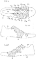
FIG. 8A, FIG. 8B and FIG. 8C are a plan view, a lateral side view and a medial side view, respectively, of the upper, wherein the area where the fastening force is needed is represented by a dotted pattern. - The present inventors sought for an eyelet arrangement that maximizes the sum ∑Fi where the distance from the eyelet HL1, HR1 on the anterior side to the eyelet HLn, HRn on the posterior side is generally constant and the number of eyelets is constant. As a result, the present inventors found that the sum ∑Fi is maximized when the average intervals D1 to Dn between eyelets of each eyelet row are alternately large and small as shown in
FIG. 7A , and made further in-depth studies to arrive at the present invention. - In a preferred embodiment of the present invention, the first average interval D1 is defined as an average value between an interval in the longitudinal direction between the first eyelet and the second eyelet of the left eyelet row and that of the right eyelet row; the second average interval D2 is defined as an average value between an interval in the longitudinal direction between the second eyelet and the third eyelet of the left eyelet row and that of the right eyelet row; and the third average interval D3 is defined as an average value between an interval in the longitudinal direction between the third eyelet and the fourth eyelet of the left eyelet row and that of the right eyelet row; and Expressions (1) and (10) below are satisfied.


- In this case, the second average interval D2 between the first average interval D1 and the third average interval D3 is small, and the average intervals are alternately large and small, which can increase the total fastening. Therefore, it is possible to improve the fitting property.
- As shown in Expression (10) above, the second average interval D2 is smaller than the first average interval D1. Therefore, the sum ∑Fi of fastening forces increases as compared with a case where the average intervals Di are equal. This increases the fastening force at the second eyelet, where a large fastening force is needed, and it is possible to improve the fitting property.
- Preferably, as shown in Expression (30) below, the third average interval D3 is set to a value that is greater than 0.65 times (D3 + D4 (fourth average interval)). This increases the sum ∑Fi of the fastening force as compared with a case where D3=D4, as will be described below.
- More preferably, Expression (5) below is further satisfied.

- In this expression, the third average interval D3 of
FIG. 7A (a schematic plan view showing eyelets and a shoelace) is set to a value that is greater than at least 0.6 times (D2+D3). Thus, the second to fourth eyelets will not be too close to each other, and it is possible to prevent the fastening force from being lopsided, as will be described below. - Note that also in
FIG. 7A , as inFIG. 7B , the fastening force Fi at each eyelet is given by Expression (100) above. - Preferably, the left and right eyelet rows each further include a fifth eyelet posterior to the fourth eyelet; a fourth average interval D4 is defined as an average value between an interval in the longitudinal direction between the fourth eyelet and the fifth eyelet of the left eyelet row and that of the right eyelet row; and Expression (6) below is satisfied.

- In this case, the fourth average interval D4 is smaller than the first average interval D1 and the third average interval D3, which can increase the total fastening. Therefore, it is possible to improve the fitting property.
- Preferably, Expression (7) below is further satisfied.

- A plurality of tendons extend along the longitudinal direction near the surface of the instep. These tendons rise when the toes are flexed. If the upper hinders this rise, it prevents smooth flexing of the foot. Particularly, the extensor hallucis longus tendon rises significantly above the MP joint. Therefore, it is preferred that the eyelets are arranged with a greater average interval between the first to third eyelets, which is located close to the MP joint, than between the third to fifth eyelets, which is remote from the MP joint.
- That is, if the eyelets are arranged according to Expression (7) above, the fastening force at the first to third eyelets arranged with a large average interval is less likely to hinder the flexing of the foot, and it is therefore likely to realize smooth flexing of the foot while maintaining a high fitting property.
- As will be described below, if the fourth average interval D4 is set to be sufficiently smaller than the second average interval D2, the fastening force may further increase.
- Therefore, it is preferred that Expression (8) or (9) below is satisfied.


- That is, depending on the application, the fastening force may be configured to be higher in the vicinity of the middle foot portion than the tip, as shown in Expression (9) above.
- Conversely, depending on the application, the fastening force may be configured to be higher in the vicinity of the tip than the middle foot portion, as shown in Expression (9') below.

- Preferably, the fourth eyelet and the fifth eyelet are spaced apart from each other in a foot width direction, and an interval W4 between the fourth eyelet and the fifth eyelet in the foot width direction is greater than the fourth average interval D4.
- If the fourth average interval D4 is decreased, the distance between eyelets may be too small, thereby partially lowering the strength of the upper, and making it more likely for the upper to rip due to the fastening force. For this, the ripping can be prevented by increasing the interval W4 in the foot width direction between the fourth eyelet and the fifth eyelet.
- Any feature illustrated and/or depicted in conjunction with one of the aforementioned aspects or the following embodiments may be used in the same or similar form in one or more of the other aspects or other embodiments, and/or may be used in combination with, or in place of, any feature of the other aspects or embodiments.
- The present invention will be understood more clearly from the following description of preferred embodiments taken in conjunction with the accompanying drawings. Note however that the embodiments and the drawings are merely illustrative and should not be taken to define the scope of the present invention. The scope of the present invention shall be defined only by the appended claims. In the accompanying drawings, like reference numerals denote like components throughout the plurality of figures.
- Embodiments of the present invention will now be described with reference to the drawings.
- In
FIG. 1A and FIG. 1B , the shoe includes an upper 41 that is integral with a sole 42 and theshoelace 40. The upper is provided with anopening 20 for inserting the foot. While this shoe is used for an athletic shoe, for example, the present invention is not limited to this. Theshoelace 40 may be removably provided on the upper 41. - In
FIG. 2 , the upper 41 defines a left eyelet row and a right eyelet row arranged along the longitudinal direction Y of the shoe. As shown inFIG. 4 , each eyelet row is composed of a plurality of eyelets HL1, HRi. Herein, left and right means these directions as seen from the wearer, and for the shoe for the right foot, left means the medial side and right means the lateral side as shown inFIG. 2 . Similarly, for the shoe for the left foot, right means the medial side and left means the lateral side. - As shown in
FIG. 2 (andFIG. 7A ), theshoelace 40 is inserted alternately through eyelets of the left eyelet row and eyelets of the right eyelet row in a crisscross pattern. In the case of this example, theshoelace 40 is strung in a horizontal straight line pattern on the tip side of the shoe, and is strung in a horizontally-elongated X-shaped pattern posterior thereto. That is, theshoelace 40 may be laced with an overlapping method or an underlapping method, or a mixture of an overlapping method and an underlapping method. - The
shoelace 40 engages with the upper 41 at the eyelets for pulling together the left side (the medial side) of the upper and the right side (the lateral side) of the upper, and fitting the side foot portions of the upper to the foot. - While eyelets are through holes formed in the upper in this example, eyelets may be rings attached to the through holes. Alternatively, eyelets may be loops or U-shaped metals.
-
FIG. 3 shows the upper before being three-dimensionally shaped into the upper 41 as shown inFIG. 2 , andFIG. 4 andFIG. 5A show partial enlarged views thereof. - In the present fastening structure of
FIG. 4 , the left and right eyelet rows each include a first eyelet HL1, HR1 on the tip side of the shoe, and a second eyelet HL2, HR2, a third eyelet HL3 , HR3, a fourth eyelet HL4, HR4, a fifth eyelet HL5, HR5 and a sixth eyelet HL6, HR6 that are arranged in this order from the first eyelet HL1, HR1 toward the posterior side, and in this example further include a seventh eyelet HL7, HR7. - In the case of an athletic shoe, the number of eyelets is in many cases six for each of the left and right eyelet rows and, accordingly, the number of eyelets may be six for each of the left and right eyelet rows. The number of eyelets may be four on each side. When it is seven on each side, it is often the case that the
shoelace 40 is not inserted through the seventh eyelets. - In
FIG. 5A , the value obtained by averaging the intervals in the longitudinal direction Y between the ith eyelets HLi, HRi and the i+1th (next posterior) eyelets HLi+1, HRi+1 for the left and right eyelet rows is denoted as the average interval Di. - That is, it is expressed as follows.
- First average interval D1 : the value obtained by averaging the intervals in the longitudinal direction Y between the first eyelets HL1, HR1 and the second eyelets HL2, HR2 for the left and right eyelet rows.
- Second average interval D2: the value obtained by averaging the intervals in the longitudinal direction Y between the second eyelets HL2, HR2 and the third eyelets HL3 , HR3 for the left and right eyelet rows.
- Third average interval D3: the value obtained by averaging the intervals in the longitudinal direction Y between the third eyelet HL3, HR3 and the fourth eyelet HL4, HR4 for the left and right eyelet rows.
- Fourth average interval D4: the value obtained by averaging the intervals in the longitudinal direction Y between the fourth eyelet HL4, HR4 and the fifth eyelet HL5, HR5 for the left and right eyelet rows.
- Herein, while the longitudinal direction Y may be considered as the longitudinal direction of the shoe, it only means the front-rear direction of the shoe in the present invention, and the direction does not need to be strictly defined. The reason is as follows.
- As shown in
FIG. 4 , in the case of this example, the left and right eyelet rows are arranged in line symmetry with each other. Therefore, the eyelet interval Li between any eyelet HLi and the next posterior eyelet HLi+1 of the left row is equal to the eyelet interval Ri between the eyelet HRi and the next posterior eyelet HRi+1 of the right row. - On the other hand, the present invention is defined by the differences or the ratio between the average intervals D1 to D4 of
FIG. 5A , and what matters is therefore the relative values of or the relative ratios between eyelet intervals rather than the absolute values of the eyelet intervals themselves. Thus, the longitudinal direction Y does not need to be uniquely defined, but may be defined to be a certain direction. For example, distances between straight lines each passing through the center points O of the left and right ith eyelets may be used as the average intervals D1 to D4 as shown inFIG. 5A of this example. - On the other hand, this similarly applies also to a case where the left and right eyelet rows are asymmetric with each other as shown in the example of
FIG. 6 . - In
FIG. 6 , an average interval Di is represented as the average value between the eyelet intervals Li and Ri. - That is, D1 to D3 are represented as shown in expressions below.


- In other words, the ith average interval Di is represented as the average value between the interval Li in the longitudinal direction Y between the left-side ith eyelet HLi and the left-side (i+1)th (next posterior) eyelet HLi+1 and the interval Ri in the longitudinal direction between the right-side ith eyelet HRi and the right-side (i+1)th (next posterior) eyelet HRi+1.
- Another method for obtaining the average interval Di of a final product of a shoe as shown in
FIG. 1A, FIG. 1B andFIG. 2 will be described. - In such a case, for the left-side eyelet row of eyelets HLi of
FIG. 2 , the eyelet intervals L1 to L5 (FIG. 4 ) along the longitudinal direction Y are obtained. Then, for the right-side eyelet row of eyelet HRi ofFIG. 2 , the eyelet intervals R1 to R5 ofFIG. 4 along the longitudinal direction Y are obtained. - Then, the average value between the eyelet intervals Li and Ri is obtained as shown in the expression below.

- Note that as the method for obtaining intervals Li and Ri and the average interval Di between eyelets of the final product of
FIG. 2 , etc., or the upper shown flattened inFIG. 3 , one may capture an image of the shoe or the upper from directly above or from a forward and upward diagonal direction and then measure the intervals on the captured image. - Next, the order among and the ratio between the average intervals D1 to D4 of
FIG. 5A will be described. - In the example of
FIG. 5A , Expressions (1), (6), (10) and (30) below are satisfied.


- The reason why the average intervals D1 to D4 are set as described above will now be described.
-
FIG. 5B shows the change of the sum ∑Fi of fastening forces from the shoelace plotted against D1/(D1+D2) or D3/(D3+D4) varied from 0 to 1.0 on the horizontal axis. - Referring to
FIG. 5B , a case where the ratio D1/(D1+D2) is varied will be discussed. - Prior to the discussion, a reinforcement area was determined that is necessary to efficiently transmit the fastening force Fi from the shoelace to the upper. As a result of the calculation, it was found that the area α represented by a dotted pattern of
FIG. 8A to FIG. 8C is important for the transmission of the fastening force. Therefore, it can be seen that in the part where the area α expands, i.e., the second eyelet HL2 (HR2) and the third eyelet HL3 (HR3 ) on the medial side (FIG. 8C ), a larger fastening force is needed than at other eyelets. On the other hand, it can be seen that on the lateral side (FIG. 8B ), a larger fastening force is needed at the second to fourth eyelets. - Now, how the area α has been determined as shown in
FIG. 8A to FIG. 8C will be discussed. - On the medial side of
FIG. 8C , the ball of the big toe protrudes outward to create a bracketed area on the medial surface of the first metatarsal bone posterior to the ball of the big toe, leading to a need to fit the upper to the medial surface of the big toe (the first toe) so that the middle foot portion of the upper conforms to the bracketed area. - On the lateral side of
FIG. 8B , the lateral surface of the foot forms an inclined, generally flat surface around the second to fourth eyelets while the upper generally forms an outwardly-protruding curved surface. This leads to a need to fit the curved upper to the inclined, generally flat surface of the foot. - Now, in
FIG. 5B , when the ratio D1/(D1+D2) becomes close to 0 from 0.4, the sum ∑Fi of fastening forces slightly increases. In this case, however, D1 ofFIG. 5A decreases, and the second eyelet HL2, HR2 comes closer to the first eyelet HL1, HR1. Now, as shown inFIG. 8A and FIG. 8B , there is no need for a large fastening force in the area around the first eyelets, and it is not preferred that the fastening force is lopsided to the anterior toe side. - Therefore, it is preferred that the ratio D1/(D1+D2) is set to a value that is greater than 0.5. Thus, it is preferred that D1>D2.
- On the other hand, when the ratio D1/(D1+D2) of
FIG. 5B comes closer to 1.0 from 0.5, the sum ∑Fi increases significantly. Particularly, when the ratio D1/(D1+D2) exceeds 0.6, the sum ∑Fi clearly increases significantly. - Therefore, the first average interval D1 and the second average interval D2 preferably satisfy Expression (10) below, and more preferably satisfy Expression (11) below.


- In Expressions (10) and (11) above, the value of the ratio D1/CD1+D2) is preferably greater than 0.6, and more preferably greater than 0.65. Note that since D2 takes a value that is greater than 0, the ratio D1/(D1+D2) is a value that is smaller than 1.
- Next, in
FIG. 5B , a case where the ratio D3/(D3+D4) is varied will be discussed. - When the ratio D3/(D3+D4) comes closer to 0 from 0.5, the sum ∑Fi of fastening forces increases. However, this is on the precondition that the second average interval D2 is decreased as described above. Therefore, in
FIG. 5A , the second average interval D2 is small and the third average interval D3 is also small. As a result, the ratio D3/(D3+D4) coming close to 0 is not preferred because the fastening force will then excessively localize around the third eyelet HL3 , HR3 . - Therefore, it is preferred that the ratio D3/(D3+D4) is set to a value that is greater than 0.5. Thus, it is preferred that D3>D4.
- On the other hand, when the ratio D3/(D3+D4) of
FIG. 5B comes closer to 1.0 from 0.5, the sum ∑Fi starts increasing about when the ratio exceeds 0.65. - Therefore, the relationship between the third average interval D3 and the fourth average interval D4 preferably satisfies Expression (30) below, more preferably satisfies Expression (31) below, and most preferably satisfies Expression (32) below.


- In Expressions (30) to (32) above, the value of the ratio D3/(D3+D4) is preferably greater than 0.65, more preferably greater than 0.7, and most preferably greater than 0.75. Note that since the fourth average interval D4 takes a value that is greater than 0, the ratio D3/(D3+D4) is a value that is smaller than 1.
- Now, the positions at which the fourth to fifth eyelets are provided typically coincide with the middle foot portion and posterior to the toes. Therefore, there is less foot deformation, and the fourth eyelet HL4 (HR4 ) and the fifth eyelet HL5 (HR5 ) can be arranged spaced apart from each other in the foot width direction as shown in
FIG. 5A in each of the left and right eyelet rows. - That is, in the case of this example, the fourth eyelet HR4 (HL4 ) and the fifth eyelet HR5 (HL5 ) are spaced apart from each other in the foot width direction, and the interval W4 between the fourth eyelet and the fifth eyelet in the foot width direction is greater than the fourth average interval D4. In the case of
FIG. 5A , while D3/(D3+D4) is set to be about 0.83, the shoelace can be arranged as shown inFIG. 2 . - From the discussion above, it can be seen that the relationship between the second average interval D2 and the fourth average interval D4 satisfies Expressions (8) and (9) below.


- Note that there is no particular limitation on the upper limit of the large average interval Di for the small average interval Dj as long as the shoelace can be arranged by providing the interval Wi (e.g., see W4 ) in the foot width direction.
- Next, the relationship between the eyelet arrangement and the toes will be discussed.
- When the tip of the big toe of the foot is raised, the extensor hallucis longus tendon significantly deforms upward. The area where the extensor hallucis longus tendon deforms significantly is directly above the MP joint, and is typically the area where the first eyelet HL1, HR1 of
FIG. 5A is arranged or the vicinity thereof. - Therefore, it will be preferred that the first to third eyelets are arranged more coarsely than the third to fifth eyelets as shown in Expression (7) below.

- Next, the relationship between the second average interval D2 and the third average interval D3 of
FIG. 5A will be discussed. - In light of the relationship between the third average interval D3 and the fourth average interval D4 of
FIG. 5B described above, it is presumed that the second average interval D2 and the third average interval D3 preferably differ from each other. On the other hand, since it is preferred that D2<D1 and D3>D4, it is preferred that D3>D2, i.e., D3>0.5*(D2+D3), as shown inFIG. 5A . With such setting, it will be possible to prevent the fastening force from localizing around the third eyelet HL3 , HR3. - Moreover, since ∑Fi increases as the value of the ratio D3/(D3+D4) of
FIG. 5B exceeds 0.6, it is preferred to satisfy Expression (5) below, and it is more preferred to satisfy Expression (50) below.

- Note that the setting is such that D3/(D2+D3)=0.69 in the example of
FIG. 5A . - As shown in
FIG. 4 andFIG. 5A , it is preferred that D5>D4 and D5>D2 for the same reason as described above. - Since Li=Ri and Di=(Li+Ri)/2 as described above, Di=Li=Ri. Therefore, in the case of this example, the relational expressions (1), ..., for the average intervals Di similarly hold true and apply for the eyelet intervals Li of the left row and for the eyelet intervals Ri of the right row.
- Now, since the inclination angles θ12 , etc., of
FIG. 7A vary depending on the distance in the width direction between left and right eyelets ofFIG. 5A . Therefore, variation in the distance in the width direction causes variation in the fastening forces Fi. However, the inclination angles θ themselves are small, and there will be no significant influence on the change of the sum ∑Fi itself with respect to the change in the ratio D1/(D1+D2) or the ratio D3/(D3+D4). Thus, there will be no need to take into consideration the distance in the width direction between left and right eyelets. - Next, an example of the specific structure of the upper will be described.
- As shown in
FIG. 2 , the anterior portion of theopening 20 may be covered by a tongue 44, for example. In the case of this example, theshoelace 40 is arranged running over the tongue 44. - In
FIG. 2 , along the edge of the anterior portion of theopening 20, the upper may be provided with a band-shapedhigh rigidity member 29 in a generally U-shaped pattern on the central side of the shoe relative to the eyelets. The member may be provided with V-shapednotches FIG. 4 is large. - In
FIG. 3 , the base fabric of the upper may be a knit or mesh material, or the like, for example. Areinforcement material 43 may be arranged on the base fabric in the area that is represented by a dotted pattern. The eyelets may be formed in the area of thereinforcement material 43. -
FIG. 6 andFIG. 8A show other embodiments. - As shown in these figures, the positions of the left and right eyelets may be asymmetric with each other. The number of eyelets may be four on each side or six on each side.
- Now, where the left and right eyelet positions are asymmetric with each other as shown in
FIG. 6 andFIG. 8A , the sum ∑Fi ofFIG. 5B may not be directly applicable. However, by obtaining the average intervals Di as shown inFIG. 6 , the inclination angles θ22, etc., ofFIG. 7A will be averaged values. That is, with the asymmetric arrangement, if the inclination angle for one of the left and right sides increases, the inclination angle for the other side decreases, thereby canceling out each other, thus resulting in averaged values. Therefore, the value will be approximate to the sum ∑Fi ofFIG. 5B also when the left and right eyelet positions are asymmetric with each other. - Next, the result of testing the actual foot conformity effect will be described. A foot conformity comparison was performed between an experimental example of this example shown in
FIG. 2 and a reference example in which the eyelets were arranged evenly spaced. As a result, it was found that the foot conformity was improved in the experimental example than in the reference example. Particularly, the fit of the upper to the foot was significantly better on the lateral side. - While preferred embodiments have been described above with reference to the drawings, various obvious changes and modifications will readily occur to those skilled in the art upon reading the present specification.
- For example, a heel counter that is continuous with the seventh eyelets may be provided in the heel portion.
- The tongue in the central portion of the upper may be absent.
- The number of eyelets may be four, five or eight or more on each side.
- The eyelets may be arranged in an inclined direction along the ridgeline of the instep or may be arranged in the opposite arrangement, in which case the average intervals may be obtained in the longitudinal direction along the ridgeline, etc..
- Thus, such changes and modifications are deemed to fall within the scope of the present invention, which is defined by the appended claims.
- While the average intervals D1 to D4 are constant with typical structures, the average intervals D1 to D4 inevitably vary slightly depending on the manufacturing process. The differences between average intervals with the present fastening structure is preferably more than that caused by such variations.
- The present invention is applicable to shoes having a lacing structure using a shoelace.
-
- 20: Opening, 21 to 23: Notches, 29: High rigidity member
- 40: Shoelace, 41: Upper, 42: Sole, 43: Reinforcement material, 44: Tongue
- 90: Extensor hallucis longus tendon
- D1 to D5: First to fifth average intervals
- HL1 to HLn, HR1 to HRn: Eyelets
- L1 to L5: Eyelet intervals for left row, R1 to R5: Eyelet intervals for right row
- W4: Interval in foot width direction
- F1 to F5: Fastening forces, T: Tension, α: Area
Claims (9)
- A fastening structure of an upper of a shoe, wherein:the upper defines a left eyelet row and a right eyelet row arranged along a longitudinal direction of the shoe;the left and right eyelet rows each at least include a first eyelet on a tip side, and a second eyelet, a third eyelet and a fourth eyelet that are arranged in this order from the first eyelet toward a posterior side;a first average interval D1 is defined as an average value between an interval in the longitudinal direction between the first eyelet and the second eyelet of the left eyelet row and an interval in the longitudinal direction between the first eleyet and the second eyelet of the right eyelet row;a second average interval D2 is defined as an average value between an interval in the longitudinal direction between the second eyelet and the third eyelet of the left eyelet row and an interval in the longitudinal direction between the second eleyet and the third eyelet of the right eyelet row;a third average interval D3 is defined as an average value between an interval in the longitudinal direction between the third eyelet and the fourth eyelet of the left eyelet row and an interval in the longitudinal direction between the third eleyet and the fourth eyelet of the right eyelet row; andExpressions (1) and (10) below are satisfied:


- The fastening structure according to claim 1, wherein Expression (11) below is satisfied:

- The fastening structure according to claim 1 or claim 2, wherein:the left and right eyelet rows each include a fifth eyelet that is arranged posterior to the fourth eyelet;a fourth average interval D4 is defined as an average value between an interval in the longitudinal direction between the fourth eyelet and the fifth eyelet of the left eyelet row and an interval in the longitudinal direction between the fourth eleyet and the fifth eyelet of the right eyelet row; andExpression (6) below is satisfied:

- The fastening structure according to claim 3, wherein Expression (7) below is further satisfied:

- The fastening structure according to claim 3, wherein Expression (8) below is further satisfied:

- The fastening structure according to claim 5, wherein Expression (9) below is further satisfied:

- The fastening structure according to claim 5, wherein Expression (9 ') below is further satisfied:

- The fastening structure according to any one of claims 3 to 7, wherein the fourth eyelet and the fifth eyelet are spaced apart from each other in a foot width direction, and an interval W4 between the fourth eyelet and the fifth eyelet in the foot width direction is greater than the fourth average interval D4.
- A shoe comprising:the fastening structure according to any one of claims 1 to 8; anda shoelace inserted through the eyelets of the left and right eyelet rows.
Applications Claiming Priority (1)
| Application Number | Priority Date | Filing Date | Title |
|---|---|---|---|
| PCT/JP2018/046294 WO2020129117A1 (en) | 2018-12-17 | 2018-12-17 | Lacing structure for shoe upper and shoe |
Publications (3)
| Publication Number | Publication Date |
|---|---|
| EP3874986A1 true EP3874986A1 (en) | 2021-09-08 |
| EP3874986A4 EP3874986A4 (en) | 2021-11-17 |
| EP3874986B1 EP3874986B1 (en) | 2025-06-25 |
Family
ID=71102089
Family Applications (1)
| Application Number | Title | Priority Date | Filing Date |
|---|---|---|---|
| EP18943357.6A Active EP3874986B1 (en) | 2018-12-17 | 2018-12-17 | Lacing structure for shoe upper and shoe |
Country Status (6)
| Country | Link |
|---|---|
| US (1) | US11819089B2 (en) |
| EP (1) | EP3874986B1 (en) |
| JP (1) | JP7357003B2 (en) |
| CN (1) | CN113226103B (en) |
| AU (1) | AU2018453822A1 (en) |
| WO (1) | WO2020129117A1 (en) |
Families Citing this family (1)
| Publication number | Priority date | Publication date | Assignee | Title |
|---|---|---|---|---|
| EP4238443A4 (en) * | 2020-12-08 | 2023-11-29 | ASICS Corporation | Upper and shoe comprising same |
Family Cites Families (12)
| Publication number | Priority date | Publication date | Assignee | Title |
|---|---|---|---|---|
| KR820002595Y1 (en) * | 1981-11-20 | 1982-12-27 | 안유호 | Shoes with prominence and depression type's link departmens |
| US4780969A (en) * | 1987-07-31 | 1988-11-01 | White Jr Samuel G | Article of footwear with improved tension distribution closure system |
| JPH01139710A (en) | 1987-11-27 | 1989-06-01 | Nisshin Steel Co Ltd | Manufacture of fine granular alloy powder |
| JPH0510649Y2 (en) * | 1988-03-08 | 1993-03-16 | ||
| JP4957978B2 (en) | 2009-07-06 | 2012-06-20 | 株式会社アシックス | Shoes with lace fitting structure |
| WO2011004422A1 (en) * | 2009-07-06 | 2011-01-13 | 株式会社アシックス | Shoe with shoelace fastener fitting structure |
| KR20110004249A (en) | 2009-07-07 | 2011-01-13 | 주식회사 버즈런 | Shoelace Fasteners |
| AU2009355126B2 (en) * | 2009-11-16 | 2013-09-05 | Asics Corporation | Shoe with improved heel fit performance |
| WO2013136514A1 (en) * | 2012-03-16 | 2013-09-19 | 株式会社アシックス | Lace-up fitting structure |
| US20150096193A1 (en) * | 2012-08-17 | 2015-04-09 | Reginald Senegal | Footwear securing system |
| US8826568B1 (en) * | 2013-08-05 | 2014-09-09 | Thomas J. Flatley | Lacing system |
| US11103029B2 (en) * | 2018-12-03 | 2021-08-31 | Cole Haan Llc | Tongueless upper with lacing system |
-
2018
- 2018-12-17 CN CN201880100128.1A patent/CN113226103B/en active Active
- 2018-12-17 WO PCT/JP2018/046294 patent/WO2020129117A1/en not_active Ceased
- 2018-12-17 AU AU2018453822A patent/AU2018453822A1/en not_active Abandoned
- 2018-12-17 US US17/312,719 patent/US11819089B2/en active Active
- 2018-12-17 EP EP18943357.6A patent/EP3874986B1/en active Active
- 2018-12-17 JP JP2020560649A patent/JP7357003B2/en active Active
Also Published As
| Publication number | Publication date |
|---|---|
| EP3874986B1 (en) | 2025-06-25 |
| US11819089B2 (en) | 2023-11-21 |
| US20220015507A1 (en) | 2022-01-20 |
| AU2018453822A1 (en) | 2021-06-24 |
| CN113226103B (en) | 2023-12-26 |
| JPWO2020129117A1 (en) | 2021-11-25 |
| WO2020129117A1 (en) | 2020-06-25 |
| CN113226103A (en) | 2021-08-06 |
| EP3874986A4 (en) | 2021-11-17 |
| JP7357003B2 (en) | 2023-10-05 |
Similar Documents
| Publication | Publication Date | Title |
|---|---|---|
| EP2826390B1 (en) | Lace-up fitting structure | |
| US20230200495A1 (en) | Sole structure for article of footwear | |
| CN110799058B (en) | Article of footwear with closure system with cabled transverse flaps | |
| CN113260268B (en) | Tongue-less upper with lacing system | |
| CN107205521B (en) | Woven footwear upper with integrated tensile strands | |
| US11617416B2 (en) | Shoe upper | |
| WO2011004619A1 (en) | Shoe provided with lace fitting structure | |
| WO2015155882A1 (en) | Shoe upper | |
| US12440000B2 (en) | Upper and shoe including the same | |
| US11076657B2 (en) | Article with zoned lacing system and method of lacing an article | |
| EP3874986B1 (en) | Lacing structure for shoe upper and shoe | |
| US20220225736A1 (en) | Shoe | |
| JP7656745B2 (en) | Shoes | |
| US11317677B2 (en) | Article with side lacing system and method of lacing an article | |
| TWI890049B (en) | Articles of footwear, knitted components and method of manufacturing articles of footwear | |
| US20230075713A1 (en) | Upper and shoe | |
| US10212989B2 (en) | Shoe having upper and sole | |
| EP4265142B1 (en) | Upper and shoe comprising same | |
| JP7352641B2 (en) | shoes | |
| JPWO2011004619A1 (en) | Shoes with lace fitting structure |
Legal Events
| Date | Code | Title | Description |
|---|---|---|---|
| STAA | Information on the status of an ep patent application or granted ep patent |
Free format text: STATUS: UNKNOWN |
|
| STAA | Information on the status of an ep patent application or granted ep patent |
Free format text: STATUS: THE INTERNATIONAL PUBLICATION HAS BEEN MADE |
|
| PUAI | Public reference made under article 153(3) epc to a published international application that has entered the european phase |
Free format text: ORIGINAL CODE: 0009012 |
|
| STAA | Information on the status of an ep patent application or granted ep patent |
Free format text: STATUS: REQUEST FOR EXAMINATION WAS MADE |
|
| 17P | Request for examination filed |
Effective date: 20210603 |
|
| AK | Designated contracting states |
Kind code of ref document: A1 Designated state(s): AL AT BE BG CH CY CZ DE DK EE ES FI FR GB GR HR HU IE IS IT LI LT LU LV MC MK MT NL NO PL PT RO RS SE SI SK SM TR |
|
| A4 | Supplementary search report drawn up and despatched |
Effective date: 20211015 |
|
| RIC1 | Information provided on ipc code assigned before grant |
Ipc: A43C 1/00 20060101ALI20211011BHEP Ipc: A43B 23/02 20060101AFI20211011BHEP |
|
| DAV | Request for validation of the european patent (deleted) | ||
| DAX | Request for extension of the european patent (deleted) | ||
| GRAP | Despatch of communication of intention to grant a patent |
Free format text: ORIGINAL CODE: EPIDOSNIGR1 |
|
| STAA | Information on the status of an ep patent application or granted ep patent |
Free format text: STATUS: GRANT OF PATENT IS INTENDED |
|
| RIC1 | Information provided on ipc code assigned before grant |
Ipc: A43C 1/00 20060101ALI20250115BHEP Ipc: A43B 23/02 20060101AFI20250115BHEP |
|
| INTG | Intention to grant announced |
Effective date: 20250124 |
|
| GRAS | Grant fee paid |
Free format text: ORIGINAL CODE: EPIDOSNIGR3 |
|
| GRAA | (expected) grant |
Free format text: ORIGINAL CODE: 0009210 |
|
| STAA | Information on the status of an ep patent application or granted ep patent |
Free format text: STATUS: THE PATENT HAS BEEN GRANTED |
|
| AK | Designated contracting states |
Kind code of ref document: B1 Designated state(s): AL AT BE BG CH CY CZ DE DK EE ES FI FR GB GR HR HU IE IS IT LI LT LU LV MC MK MT NL NO PL PT RO RS SE SI SK SM TR |
|
| REG | Reference to a national code |
Ref country code: GB Ref legal event code: FG4D |
|
| REG | Reference to a national code |
Ref country code: CH Ref legal event code: EP |
|
| REG | Reference to a national code |
Ref country code: DE Ref legal event code: R096 Ref document number: 602018083070 Country of ref document: DE |
|
| REG | Reference to a national code |
Ref country code: CH Ref legal event code: EP |
|
| REG | Reference to a national code |
Ref country code: IE Ref legal event code: FG4D |
|
| PG25 | Lapsed in a contracting state [announced via postgrant information from national office to epo] |
Ref country code: FI Free format text: LAPSE BECAUSE OF FAILURE TO SUBMIT A TRANSLATION OF THE DESCRIPTION OR TO PAY THE FEE WITHIN THE PRESCRIBED TIME-LIMIT Effective date: 20250625 |
|
| REG | Reference to a national code |
Ref country code: LT Ref legal event code: MG9D |
|
| PG25 | Lapsed in a contracting state [announced via postgrant information from national office to epo] |
Ref country code: NO Free format text: LAPSE BECAUSE OF FAILURE TO SUBMIT A TRANSLATION OF THE DESCRIPTION OR TO PAY THE FEE WITHIN THE PRESCRIBED TIME-LIMIT Effective date: 20250925 Ref country code: GR Free format text: LAPSE BECAUSE OF FAILURE TO SUBMIT A TRANSLATION OF THE DESCRIPTION OR TO PAY THE FEE WITHIN THE PRESCRIBED TIME-LIMIT Effective date: 20250926 |
|
| PG25 | Lapsed in a contracting state [announced via postgrant information from national office to epo] |
Ref country code: BG Free format text: LAPSE BECAUSE OF FAILURE TO SUBMIT A TRANSLATION OF THE DESCRIPTION OR TO PAY THE FEE WITHIN THE PRESCRIBED TIME-LIMIT Effective date: 20250625 |
|
| PG25 | Lapsed in a contracting state [announced via postgrant information from national office to epo] |
Ref country code: HR Free format text: LAPSE BECAUSE OF FAILURE TO SUBMIT A TRANSLATION OF THE DESCRIPTION OR TO PAY THE FEE WITHIN THE PRESCRIBED TIME-LIMIT Effective date: 20250625 |
|
| PG25 | Lapsed in a contracting state [announced via postgrant information from national office to epo] |
Ref country code: RS Free format text: LAPSE BECAUSE OF FAILURE TO SUBMIT A TRANSLATION OF THE DESCRIPTION OR TO PAY THE FEE WITHIN THE PRESCRIBED TIME-LIMIT Effective date: 20250925 |
|
| PG25 | Lapsed in a contracting state [announced via postgrant information from national office to epo] |
Ref country code: LV Free format text: LAPSE BECAUSE OF FAILURE TO SUBMIT A TRANSLATION OF THE DESCRIPTION OR TO PAY THE FEE WITHIN THE PRESCRIBED TIME-LIMIT Effective date: 20250625 |
|
| REG | Reference to a national code |
Ref country code: NL Ref legal event code: MP Effective date: 20250625 |
|
| PG25 | Lapsed in a contracting state [announced via postgrant information from national office to epo] |
Ref country code: NL Free format text: LAPSE BECAUSE OF FAILURE TO SUBMIT A TRANSLATION OF THE DESCRIPTION OR TO PAY THE FEE WITHIN THE PRESCRIBED TIME-LIMIT Effective date: 20250625 |
|
| PG25 | Lapsed in a contracting state [announced via postgrant information from national office to epo] |
Ref country code: PT Free format text: LAPSE BECAUSE OF FAILURE TO SUBMIT A TRANSLATION OF THE DESCRIPTION OR TO PAY THE FEE WITHIN THE PRESCRIBED TIME-LIMIT Effective date: 20251027 |
|
| REG | Reference to a national code |
Ref country code: AT Ref legal event code: MK05 Ref document number: 1805523 Country of ref document: AT Kind code of ref document: T Effective date: 20250625 |
|
| PG25 | Lapsed in a contracting state [announced via postgrant information from national office to epo] |
Ref country code: IS Free format text: LAPSE BECAUSE OF FAILURE TO SUBMIT A TRANSLATION OF THE DESCRIPTION OR TO PAY THE FEE WITHIN THE PRESCRIBED TIME-LIMIT Effective date: 20251025 |
|
| PGFP | Annual fee paid to national office [announced via postgrant information from national office to epo] |
Ref country code: DE Payment date: 20251028 Year of fee payment: 8 |
|
| PG25 | Lapsed in a contracting state [announced via postgrant information from national office to epo] |
Ref country code: SM Free format text: LAPSE BECAUSE OF FAILURE TO SUBMIT A TRANSLATION OF THE DESCRIPTION OR TO PAY THE FEE WITHIN THE PRESCRIBED TIME-LIMIT Effective date: 20250625 Ref country code: AT Free format text: LAPSE BECAUSE OF FAILURE TO SUBMIT A TRANSLATION OF THE DESCRIPTION OR TO PAY THE FEE WITHIN THE PRESCRIBED TIME-LIMIT Effective date: 20250625 |
|
| PG25 | Lapsed in a contracting state [announced via postgrant information from national office to epo] |
Ref country code: CZ Free format text: LAPSE BECAUSE OF FAILURE TO SUBMIT A TRANSLATION OF THE DESCRIPTION OR TO PAY THE FEE WITHIN THE PRESCRIBED TIME-LIMIT Effective date: 20250625 |
|
| PG25 | Lapsed in a contracting state [announced via postgrant information from national office to epo] |
Ref country code: PL Free format text: LAPSE BECAUSE OF FAILURE TO SUBMIT A TRANSLATION OF THE DESCRIPTION OR TO PAY THE FEE WITHIN THE PRESCRIBED TIME-LIMIT Effective date: 20250625 |
|
| PG25 | Lapsed in a contracting state [announced via postgrant information from national office to epo] |
Ref country code: EE Free format text: LAPSE BECAUSE OF FAILURE TO SUBMIT A TRANSLATION OF THE DESCRIPTION OR TO PAY THE FEE WITHIN THE PRESCRIBED TIME-LIMIT Effective date: 20250625 |
|
| PG25 | Lapsed in a contracting state [announced via postgrant information from national office to epo] |
Ref country code: SK Free format text: LAPSE BECAUSE OF FAILURE TO SUBMIT A TRANSLATION OF THE DESCRIPTION OR TO PAY THE FEE WITHIN THE PRESCRIBED TIME-LIMIT Effective date: 20250625 |
|
| PG25 | Lapsed in a contracting state [announced via postgrant information from national office to epo] |
Ref country code: ES Free format text: LAPSE BECAUSE OF FAILURE TO SUBMIT A TRANSLATION OF THE DESCRIPTION OR TO PAY THE FEE WITHIN THE PRESCRIBED TIME-LIMIT Effective date: 20250625 |
|
| PG25 | Lapsed in a contracting state [announced via postgrant information from national office to epo] |
Ref country code: RO Free format text: LAPSE BECAUSE OF FAILURE TO SUBMIT A TRANSLATION OF THE DESCRIPTION OR TO PAY THE FEE WITHIN THE PRESCRIBED TIME-LIMIT Effective date: 20250625 |
|
| PG25 | Lapsed in a contracting state [announced via postgrant information from national office to epo] |
Ref country code: DK Free format text: LAPSE BECAUSE OF FAILURE TO SUBMIT A TRANSLATION OF THE DESCRIPTION OR TO PAY THE FEE WITHIN THE PRESCRIBED TIME-LIMIT Effective date: 20250625 |
|
| PG25 | Lapsed in a contracting state [announced via postgrant information from national office to epo] |
Ref country code: IT Free format text: LAPSE BECAUSE OF FAILURE TO SUBMIT A TRANSLATION OF THE DESCRIPTION OR TO PAY THE FEE WITHIN THE PRESCRIBED TIME-LIMIT Effective date: 20250625 |
|
| PLBE | No opposition filed within time limit |
Free format text: ORIGINAL CODE: 0009261 |
|
| STAA | Information on the status of an ep patent application or granted ep patent |
Free format text: STATUS: NO OPPOSITION FILED WITHIN TIME LIMIT |
|
| REG | Reference to a national code |
Ref country code: CH Ref legal event code: L10 Free format text: ST27 STATUS EVENT CODE: U-0-0-L10-L00 (AS PROVIDED BY THE NATIONAL OFFICE) Effective date: 20260507 |