EP3874525B1 - Passive electrical component for safety system shutdown using gauss' law of magnetism - Google Patents
Passive electrical component for safety system shutdown using gauss' law of magnetism Download PDFInfo
- Publication number
- EP3874525B1 EP3874525B1 EP19842847.6A EP19842847A EP3874525B1 EP 3874525 B1 EP3874525 B1 EP 3874525B1 EP 19842847 A EP19842847 A EP 19842847A EP 3874525 B1 EP3874525 B1 EP 3874525B1
- Authority
- EP
- European Patent Office
- Prior art keywords
- electrical connection
- bar magnet
- law
- electro
- magnetism
- Prior art date
- Legal status (The legal status is an assumption and is not a legal conclusion. Google has not performed a legal analysis and makes no representation as to the accuracy of the status listed.)
- Active
Links
Images


Classifications
-
- G—PHYSICS
- G21—NUCLEAR PHYSICS; NUCLEAR ENGINEERING
- G21D—NUCLEAR POWER PLANT
- G21D3/00—Control of nuclear power plant
- G21D3/04—Safety arrangements
- G21D3/06—Safety arrangements responsive to faults within the plant
-
- G—PHYSICS
- G21—NUCLEAR PHYSICS; NUCLEAR ENGINEERING
- G21C—NUCLEAR REACTORS
- G21C9/00—Emergency protection arrangements structurally associated with the reactor, e.g. safety valves provided with pressure equalisation devices
-
- G—PHYSICS
- G21—NUCLEAR PHYSICS; NUCLEAR ENGINEERING
- G21C—NUCLEAR REACTORS
- G21C7/00—Control of nuclear reaction
- G21C7/36—Control circuits
-
- G—PHYSICS
- G21—NUCLEAR PHYSICS; NUCLEAR ENGINEERING
- G21C—NUCLEAR REACTORS
- G21C9/00—Emergency protection arrangements structurally associated with the reactor, e.g. safety valves provided with pressure equalisation devices
- G21C9/004—Pressure suppression
- G21C9/012—Pressure suppression by thermal accumulation or by steam condensation, e.g. ice condensers
-
- G—PHYSICS
- G21—NUCLEAR PHYSICS; NUCLEAR ENGINEERING
- G21C—NUCLEAR REACTORS
- G21C9/00—Emergency protection arrangements structurally associated with the reactor, e.g. safety valves provided with pressure equalisation devices
- G21C9/02—Means for effecting very rapid reduction of the reactivity factor under fault conditions, e.g. reactor fuse; Control elements having arrangements activated in an emergency
-
- H—ELECTRICITY
- H01—ELECTRIC ELEMENTS
- H01H—ELECTRIC SWITCHES; RELAYS; SELECTORS; EMERGENCY PROTECTIVE DEVICES
- H01H50/00—Details of electromagnetic relays
- H01H50/005—Details of electromagnetic relays using micromechanics
-
- Y—GENERAL TAGGING OF NEW TECHNOLOGICAL DEVELOPMENTS; GENERAL TAGGING OF CROSS-SECTIONAL TECHNOLOGIES SPANNING OVER SEVERAL SECTIONS OF THE IPC; TECHNICAL SUBJECTS COVERED BY FORMER USPC CROSS-REFERENCE ART COLLECTIONS [XRACs] AND DIGESTS
- Y02—TECHNOLOGIES OR APPLICATIONS FOR MITIGATION OR ADAPTATION AGAINST CLIMATE CHANGE
- Y02E—REDUCTION OF GREENHOUSE GAS [GHG] EMISSIONS, RELATED TO ENERGY GENERATION, TRANSMISSION OR DISTRIBUTION
- Y02E30/00—Energy generation of nuclear origin
-
- Y—GENERAL TAGGING OF NEW TECHNOLOGICAL DEVELOPMENTS; GENERAL TAGGING OF CROSS-SECTIONAL TECHNOLOGIES SPANNING OVER SEVERAL SECTIONS OF THE IPC; TECHNICAL SUBJECTS COVERED BY FORMER USPC CROSS-REFERENCE ART COLLECTIONS [XRACs] AND DIGESTS
- Y02—TECHNOLOGIES OR APPLICATIONS FOR MITIGATION OR ADAPTATION AGAINST CLIMATE CHANGE
- Y02E—REDUCTION OF GREENHOUSE GAS [GHG] EMISSIONS, RELATED TO ENERGY GENERATION, TRANSMISSION OR DISTRIBUTION
- Y02E30/00—Energy generation of nuclear origin
- Y02E30/30—Nuclear fission reactors
Definitions
- the present disclosure relates to a safety system shutdown including a passive electrical component that senses a system parameter and becomes tripped if a predetermined set point is reached so that a signal is sent to take an action in the system.
- the passive electrical component makes use of the principles of Gauss' Law of Magnetism.
- DCIS Distributed Control and Information System
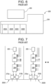
- FIG 6 schematically shows a conventional distributed control and information system (DCIS) 200 with both a safety portion 202 and non-safety portion 204 that are interfaced by a control panel 203.
- the present disclosure is directed to the safety portion 202 of the DCIS 200 which is shown in Figure 7 .
- the safety portion 202 of the DCIS 200 includes four independently designed divisions 202A-202D which each receive measured system signals that are collected and sent from a remote multiplexer unit RMU 205 which provides output to the digital trip module DTM 206 which each provide outputs to the trip logic units TLU 208 which each provide an output signal to the output logic unit OLU 210.
- the conventional safety portions 202 use a voting logic of at least 2 out of 4 of the different divisions 202A-202d receiving like signals in order to determine a fault (i.e. pressures and temperatures are not compared against each other). It becomes more difficult for the nuclear power plant control system designer, purchaser, installer, and operator to establish and trace the essential safety signals to ensure the system is performing as designed. A device and method is needed on a scale that humans can vary "signal flow” or "trace the flow of electrons/data so that the system is immune from cyber-attack.
- a relay (300) has electromagnet (20) that produces magnetic field (Hs) perpendicular to magnetization direction of hard movable magnets (11,51) of coils (10,50).
- the magnetic field interacts and exerts magnetic torque on hard movable magnets, to rotate hard movable magnets in different directions, until contacts (14,54) contact contacts (42,62) and contacts (13,53) do not contact contacts (41,61).
- the current pulse in the coils is reversed to reverse the direction of torque so that hard movable magnets move to close contacts (13,53) with contacts (41,61).
- the present disclosure provides electro-technical devices that, coupled to control systems, can provide passive system safety shutdown using Guass' Law of magnetism. These devices will solve the issue of common cause software failure or cyber security attacks that are inherent limitations of digital safety systems.
- the Gauss Law of magnetism contactor provides an electro-technical device that can be set up in multiple configurations to protect a nuclear power plant, or another sensitive infrastructure.
- the Gauss Law of magnetism contactor can be produced using metallic and plastic 3-D printing machines that can be utilized to ensure consistent manufacture of the electrotechnical device for which the manufacturing data can be captured and stored for utilization in confirming the device's consistent operational characteristics.
- the devices use a simple pass/fail or go/no-go check to convey to an electrical safety system to change state to safe shutdown.
- the printed device is placed into the safety system to perform 3 basic tasks: sense a system parameter (e.g. temperature, flow, pressure, power or rate of change), if the predetermined set point is reached - result in a "tripped" state, and lastly, if the safety system logic is met - send a signal to take an action in the system, such as shutdown.
- a system parameter e.g. temperature, flow, pressure, power or rate of change
- the safety system logic is met - send a signal to take an action in the system, such as shutdown.
- the Gauss Law of magnetism contactor can fail as either is or fail in a safe state, depending on user requirements.
- the system prevents any loss of the safety function of the digital device due to power outage.
- the device also eliminates failures due to software or digital cyber-attacks.
- the at least one coil includes a pair of coils disposed on opposite sides of the bar magnet and each being supplied with an electronic signal from a sensor
- a fault detection system for a nuclear reactor includes a plurality of contactors each including an input electrical connection supplied with an input signal and electrically isolated from an output electrical connection.
- a bar magnet is pivotally mounted on a pedicel between the input electrical connection and the output electrical connection and a pair of coils are disposed on opposite sides of the bar magnet and each being supplied with an electronic signal from a sensor.
- the bar magnet is responsive to an electromagnetic field generated by the pair of coils to cause the bar magnet to contact the input electrical connection and the output electrical connection and complete a circuit and send out a control signal.
- Example embodiments are provided so that this disclosure will be thorough, and will fully convey the scope to those who are skilled in the art. Numerous specific details are set forth such as examples of specific components, devices, and methods, to provide a thorough understanding of embodiments of the present disclosure. It will be apparent to those skilled in the art that specific details need not be employed, that example embodiments may be embodied in many different forms and that neither should be construed to limit the scope of the disclosure. In some example embodiments, well-known processes, well-known device structures, and well-known technologies are not described in detail.
- the Gauss Law of Magnetism contactor 10 includes an input signal 12 having an electrical connection point 14 and an output signal 16 having an electrical connection point 18.
- an open state is shown.
- the Gauss Law of Magnetism contactor 10 includes a bar magnet 20 rotatably supported on a pedicel 22 between the input electrical connection point 14 and the output electrical connection point 18.
- a first coil 24 is positioned adjacent to the input electrical connection point 14 and a second coil 26 is positioned adjacent to the output electrical connection point 18.
- One or both of the coils 24, 26 can have an electrical current passing through them (i.e.
- Figure 2 shows that repositioning of the bar magnet 20 due to increased current flow from the sensors 28, 30 passing through the coils 24, 26 causing the electrical connection between the input electrical connection 14 and output electrical connection point 18 so that a safety system action signal 32 can be sent.
- Figure 3 provides a side view of the Gauss Law of Magnetism contactor 10 illustrating the magnet 20 placed inside a non-magnetic box 34 on the pedicel 22. The magnet 20 rotates about the pedicel 22, and the box 34 is sealed with a lid 36.
- the reverse circuit can be set up to open (rather than close) the Gauss Law of Magnetism contactor 10 to de-energize a system for a protective feature.
- Figures 4 and 5 provide a schematic view of a nuclear safety system 40 using Gauss' Law of Magnetism.
- the nuclear safety system 40 utilizes four independent divisions 42A-42D for each division of the safety system.
- a 4-division safety system utilizing a 2 out of 4 logic of like signals (A, B, C, D)
- there are six states including AB, AC, AD, BC, BD and CD to reach a tripped state.
- Figure 4 provides a side view in the X and Z plane. In the positive Z direction, the AB, AC and AD trip states are attained by the Gauss magnetism Law contactors 50A, 50B and 50C, respectively.
- the Gauss Magnetism law contactor 50A receives current through the respective coils 66A, 66B from the divisions 42A and 42B.
- the Gauss Magnetism law contactor 50B receives current through the respective coils 66A, 66C from the divisions 42A and 42C.
- the Gauss Magnetism law contactor 50C receives current through the respective coils 66A, 66D from the divisions 42A and 42D.
- the BC and BD trip states are attained by the Gauss Magnetism law contactors 50D, 50E, respectively.
- the Gauss Magnetism law contactor 50D receives current through the respective coils 66B, 66C from the divisions 42B and 42C.
- the Gauss Magnetism law contactor 50E receives current through the respective coils 66B, 66D from the divisions 42B, and 42D.
- Figure 5 provides a side view in the positive Y direction which provides the CD tripped state.
- the Gauss Magnetism law contactor 50F receives current through the respective coils 66C, 66D from the divisions 42C and 42D.Thus, sensors from two out of four divisions 42A-42D can be activated causing an increased current to flow through the two respective coils 66A-66D and triggering one or more of the Gauss magnetism law contactors 50A-50F in any of 6 states so that an output signal is sent and a safety action occurs.
- the six Gauss magnetism law contactors 50A-50F replace the DTM, TLU and OLU of the safety divisions 202A-202D previously described in Figures 6 and 7 .
- a current (4 to 20 mA) is supplied to drive the devices. If the current exceeds the device baseline due to, for example, a sensed temperature rise above a predetermined level or a pressure rise above a predetermined level, the safety system response is actuated. If there is a loss of primary power, an uninterruptible power supply is used to maintain a constant voltage level within the circuitry. The electricity from this secondary supply will also be fed to the safety measuring devices, and the loss results in the safe shutdown of the system. In the event of a loss of all power, then the system either fails as is or to a safety state, depending on how the device is placed into an architecture by the circuit designer.
Landscapes
- Physics & Mathematics (AREA)
- Engineering & Computer Science (AREA)
- Plasma & Fusion (AREA)
- General Engineering & Computer Science (AREA)
- High Energy & Nuclear Physics (AREA)
- Emergency Management (AREA)
- Business, Economics & Management (AREA)
- Chemical & Material Sciences (AREA)
- Chemical Kinetics & Catalysis (AREA)
- Electromagnetism (AREA)
- Monitoring And Testing Of Nuclear Reactors (AREA)
- Testing And Monitoring For Control Systems (AREA)
- Magnetic Resonance Imaging Apparatus (AREA)
Description
- The present disclosure relates to a safety system shutdown including a passive electrical component that senses a system parameter and becomes tripped if a predetermined set point is reached so that a signal is sent to take an action in the system. The passive electrical component makes use of the principles of Gauss' Law of Magnetism.
- This section provides background information related to the present disclosure which is not necessarily prior art.
- Modern nuclear reactors use a variety of digital systems for both control and safety, referred to as a Distributed Control and Information System (DCIS). These systems must be redundant, diverse, fault tolerant, and have extensive self-diagnosis while the system is in operation. Meanwhile, the nuclear digital industry is concerned with common cause software failure. Even more damaging is a cyberattack to, or through, the system safety systems. In the digital industry, the desire to increase computational power while decreasing component size results in a very small digital device with embedded software. It is very difficult to convince a regulatory body that these systems cannot have a common cause failure. Even more damaging operations can occur when this compact digital system is subjected to a cyberattack. These extreme unknown conditions of a nuclear power plant safety system lead to the cause for redundancy, independence, and determinacy, all of which contribute to significant added cost.
-
Figure 6 schematically shows a conventional distributed control and information system (DCIS) 200 with both a safety portion 202 andnon-safety portion 204 that are interfaced by acontrol panel 203. The present disclosure is directed to the safety portion 202 of theDCIS 200 which is shown inFigure 7 . The safety portion 202 of the DCIS 200 includes four independently designeddivisions 202A-202D which each receive measured system signals that are collected and sent from a remote multiplexer unit RMU 205 which provides output to the digital trip module DTM 206 which each provide outputs to the trip logic units TLU 208 which each provide an output signal to the output logic unit OLU 210. The conventional safety portions 202 use a voting logic of at least 2 out of 4 of thedifferent divisions 202A-202d receiving like signals in order to determine a fault (i.e. pressures and temperatures are not compared against each other). It becomes more difficult for the nuclear power plant control system designer, purchaser, installer, and operator to establish and trace the essential safety signals to ensure the system is performing as designed. A device and method is needed on a scale that humans can vary "signal flow" or "trace the flow of electrons/data so that the system is immune from cyber-attack. - Prior art document
US2009261927A1 discloses (the reference signs referring to this document) a relay (300) has electromagnet (20) that produces magnetic field (Hs) perpendicular to magnetization direction of hard movable magnets (11,51) of coils (10,50). The magnetic field interacts and exerts magnetic torque on hard movable magnets, to rotate hard movable magnets in different directions, until contacts (14,54) contact contacts (42,62) and contacts (13,53) do not contact contacts (41,61). The current pulse in the coils, is reversed to reverse the direction of torque so that hard movable magnets move to close contacts (13,53) with contacts (41,61). - This section provides a general summary of the disclosure, and is not a comprehensive disclosure of its full scope or all of its features.
- The present disclosure provides electro-technical devices that, coupled to control systems, can provide passive system safety shutdown using Guass' Law of magnetism. These devices will solve the issue of common cause software failure or cyber security attacks that are inherent limitations of digital safety systems. The Gauss Law of magnetism contactor provides an electro-technical device that can be set up in multiple configurations to protect a nuclear power plant, or another sensitive infrastructure. The Gauss Law of magnetism contactor can be produced using metallic and plastic 3-D printing machines that can be utilized to ensure consistent manufacture of the electrotechnical device for which the manufacturing data can be captured and stored for utilization in confirming the device's consistent operational characteristics. The devices use a simple pass/fail or go/no-go check to convey to an electrical safety system to change state to safe shutdown. The printed device is placed into the safety system to perform 3 basic tasks: sense a system parameter (e.g. temperature, flow, pressure, power or rate of change), if the predetermined set point is reached - result in a "tripped" state, and lastly, if the safety system logic is met - send a signal to take an action in the system, such as shutdown. In the event of normal power supply loss, the Gauss Law of magnetism contactor can fail as either is or fail in a safe state, depending on user requirements. The system prevents any loss of the safety function of the digital device due to power outage. The device also eliminates failures due to software or digital cyber-attacks.
- The present invention is defined in appended claim 1.
- According to a further aspect, the at least one coil includes a pair of coils disposed on opposite sides of the bar magnet and each being supplied with an electronic signal from a sensor
- A fault detection system for a nuclear reactor includes a plurality of contactors each including an input electrical connection supplied with an input signal and electrically isolated from an output electrical connection. A bar magnet is pivotally mounted on a pedicel between the input electrical connection and the output electrical connection and a pair of coils are disposed on opposite sides of the bar magnet and each being supplied with an electronic signal from a sensor. The bar magnet is responsive to an electromagnetic field generated by the pair of coils to cause the bar magnet to contact the input electrical connection and the output electrical connection and complete a circuit and send out a control signal.
- Further areas of applicability will become apparent from the description provided herein. The description and specific examples in this summary are intended for purposes of illustration only and are not intended to limit the scope of the present disclosure.
- The drawings described herein are for illustrative purposes only of selected embodiments and not all possible implementations, and are not intended to limit the scope of the present disclosure.
-
Figure 1 is a schematic illustration of a Gauss Law of Magnetism contactor according to the principles of the present disclosure shown in an open state; -
Figure 2 is a schematic illustration of the Gauss Magnetism law contactor shown inFigure 1 shown in a closed state; -
Figure 3 is a schematic side view of the Gauss Magnetism law contactor shown inFigure 1 ; -
Figure 4 is a schematic side view in the X and Z plane of a Gauss Magnetism law contactor having multiple inputs according to the principles of the present disclosure; -
Figure 5 is a schematic side view in the Z-direction of a Gauss Magnetism law contactor having multiple inputs according to the principles of the present disclosure; -
Figure 6 is a schematic view of a conventional digital system of a distributed control and information system for a nuclear reactor; and -
Figure 7 is a schematic view of a safety portion of the conventional digital system of a distributed control and information system as shown inFigure 6 . - Corresponding reference numerals indicate corresponding parts throughout the several views of the drawings.
- Example embodiments will now be described more fully with reference to the accompanying drawings.
- Example embodiments are provided so that this disclosure will be thorough, and will fully convey the scope to those who are skilled in the art. Numerous specific details are set forth such as examples of specific components, devices, and methods, to provide a thorough understanding of embodiments of the present disclosure. It will be apparent to those skilled in the art that specific details need not be employed, that example embodiments may be embodied in many different forms and that neither should be construed to limit the scope of the disclosure. In some example embodiments, well-known processes, well-known device structures, and well-known technologies are not described in detail.
- The terminology used herein is for the purpose of describing particular example embodiments only and is not intended to be limiting. As used herein, the singular forms "a," "an," and "the" may be intended to include the plural forms as well, unless the context clearly indicates otherwise. The terms "comprises," "comprising," "including," and "having," are inclusive and therefore specify the presence of stated features, integers, steps, operations, elements, and/or components, but do not preclude the presence or addition of one or more other features, integers, steps, operations, elements, components, and/or groups thereof. The method steps, processes, and operations described herein are not to be construed as necessarily requiring their performance in the particular order discussed or illustrated, unless specifically identified as an order of performance. It is also to be understood that additional or alternative steps may be employed.
- With reference to
Figures 1-3 , a Gauss Law of Magnetismcontactor 10 according to the principles of the present disclosure will now be described. As shown inFigure 1 , the Gauss Law ofMagnetism contactor 10 includes aninput signal 12 having anelectrical connection point 14 and anoutput signal 16 having anelectrical connection point 18. InFigure 1 , an open state is shown. The Gauss Law of Magnetismcontactor 10 includes abar magnet 20 rotatably supported on apedicel 22 between the inputelectrical connection point 14 and the outputelectrical connection point 18. Afirst coil 24 is positioned adjacent to the inputelectrical connection point 14 and asecond coil 26 is positioned adjacent to the outputelectrical connection point 18. One or both of thecoils sensors coils electrical connection point 14 and the north pole in the region of theoutput connection point 18. These externally induced magnetic fields result in the magnetic rotation of thebar magnet 20. -
Figure 2 shows that repositioning of thebar magnet 20 due to increased current flow from thesensors coils electrical connection 14 and outputelectrical connection point 18 so that a safetysystem action signal 32 can be sent.Figure 3 provides a side view of the Gauss Law ofMagnetism contactor 10 illustrating themagnet 20 placed inside anon-magnetic box 34 on thepedicel 22. Themagnet 20 rotates about thepedicel 22, and thebox 34 is sealed with alid 36. As an alternative, the reverse circuit can be set up to open (rather than close) the Gauss Law ofMagnetism contactor 10 to de-energize a system for a protective feature. -
Figures 4 and 5 provide a schematic view of anuclear safety system 40 using Gauss' Law of Magnetism. Thenuclear safety system 40 utilizes fourindependent divisions 42A-42D for each division of the safety system. In a 4-division safety system utilizing a 2 out of 4 logic of like signals (A, B, C, D), there are six states including AB, AC, AD, BC, BD and CD to reach a tripped state.Figure 4 provides a side view in the X and Z plane. In the positive Z direction, the AB, AC and AD trip states are attained by the Gauss magnetism Law contactors 50A, 50B and 50C, respectively. The GaussMagnetism law contactor 50A receives current through therespective coils divisions Magnetism law contactor 50B receives current through therespective coils divisions Magnetism law contactor 50C receives current through therespective coils divisions Magnetism law contactors Magnetism law contactor 50D receives current through therespective coils divisions Magnetism law contactor 50E receives current through therespective coils divisions Figure 5 provides a side view in the positive Y direction which provides the CD tripped state. The GaussMagnetism law contactor 50F receives current through therespective coils divisions 42C and 42D.Thus, sensors from two out of fourdivisions 42A-42D can be activated causing an increased current to flow through the tworespective coils 66A-66D and triggering one or more of the Gauss magnetism law contactors 50A-50F in any of 6 states so that an output signal is sent and a safety action occurs. The six Gauss magnetism law contactors 50A-50F replace the DTM, TLU and OLU of thesafety divisions 202A-202D previously described inFigures 6 and 7 . - The present disclosure envisions the use of the following operating modes. During steady-state operation of the devices, a current (4 to 20 mA) is supplied to drive the devices. If the current exceeds the device baseline due to, for example, a sensed temperature rise above a predetermined level or a pressure rise above a predetermined level, the safety system response is actuated. If there is a loss of primary power, an uninterruptible power supply is used to maintain a constant voltage level within the circuitry. The electricity from this secondary supply will also be fed to the safety measuring devices, and the loss results in the safe shutdown of the system. In the event of a loss of all power, then the system either fails as is or to a safety state, depending on how the device is placed into an architecture by the circuit designer.
Claims (4)
- An electro-technical device (10), comprising:an input electrical connection (14) supplied with an input signal (12) and electrically isolated from an output electrical connection (18); anda bar magnet (20) pivotally mounted on a pedicel (22) between the input electrical connection (14) and the output electrical connection (18); andat least one coil (24) disposed adjacent to the bar magnet (20) and being supplied with an electronic signal from a sensor (28) external to electro-technical device (10),the electro-technical device (10) characterized in thatthe bar magnet (20) being responsive to an electromagnetic field generated by the at least one coil (24) to cause the bar magnet (20) to pivot to simultaneously come into contact with both the input electrical connection (14) and the output electrical connection (18) and complete a circuit and send out a control signal.
- The electro-technical device (10) according to claim 1, further comprising a housing (34) for enclosing the bar magnet (20), the pedicel (22), the input electrical connection (14) and the output electrical connection (18).
- The electro-technical device (10) according to claim 1, wherein the at least one coil (24) includes a pair of coils (24, 26) includinga first coil (24) connected to one of a temperature sensor, a pressure sensor and a flow sensor anda second coil (26) connected to a second one of a temperature sensor, a pressure sensor and a flow sensor,said sensors external to the electro-technical device (10).
- A method of making an electro-technical device (10), comprising:forming a housing (34) by 3-D printing and including an input electrical connection (14) supplied with an input signal (12) and electrically isolated from an output electrical connection (18);3-D printing a pedicel (22) in the housing (34);placing a bar magnet (20) pivotally mounted on the pedicel (22) between the input electrical connection (14) and the output electrical connection (18); and3-D printing at least one coil (24) disposed adjacent to the bar magnet (20) and being supplied with an electronic signal from a sensor (28) external to electro-technical device (10), the bar magnet (20) being responsive to an electromagnetic field generated by the at least one coil (24) to cause the bar magnet (20) to pivot to simultaneously come into contact with both the input electrical connection (14) and the output electrical connection (18) and complete a circuit and send out a control signal.
Applications Claiming Priority (2)
| Application Number | Priority Date | Filing Date | Title |
|---|---|---|---|
| US16/176,618 US11170906B2 (en) | 2018-10-31 | 2018-10-31 | Passive electrical component for safety system shutdown using Gauss' law of magnetism |
| PCT/US2019/058506 WO2020092328A1 (en) | 2018-10-31 | 2019-10-29 | Passive electrical component for safety system shutdown using gauss' law of magnetism |
Publications (2)
| Publication Number | Publication Date |
|---|---|
| EP3874525A1 EP3874525A1 (en) | 2021-09-08 |
| EP3874525B1 true EP3874525B1 (en) | 2023-07-26 |
Family
ID=69232885
Family Applications (1)
| Application Number | Title | Priority Date | Filing Date |
|---|---|---|---|
| EP19842847.6A Active EP3874525B1 (en) | 2018-10-31 | 2019-10-29 | Passive electrical component for safety system shutdown using gauss' law of magnetism |
Country Status (5)
| Country | Link |
|---|---|
| US (1) | US11170906B2 (en) |
| EP (1) | EP3874525B1 (en) |
| JP (1) | JP7285919B2 (en) |
| PL (1) | PL3874525T3 (en) |
| WO (1) | WO2020092328A1 (en) |
Family Cites Families (12)
| Publication number | Priority date | Publication date | Assignee | Title |
|---|---|---|---|---|
| DE879567C (en) | 1951-07-10 | 1953-04-30 | Remimax Aktiebolag | Electromagnetically controlled current pulse relay |
| NL113562C (en) | 1959-02-24 | |||
| US3660231A (en) | 1968-11-26 | 1972-05-02 | Gen Electric | Steam cooled nuclear reactor |
| JPS5414345U (en) * | 1977-07-04 | 1979-01-30 | ||
| US4957690A (en) | 1988-12-07 | 1990-09-18 | General Electric Company | System and method for monitoring and control of safety-related components of a nuclear power plant |
| US4949362A (en) | 1989-03-09 | 1990-08-14 | General Electric Company | System for detecting and limiting electrical ground faults within electrical devices |
| JPH0731480Y2 (en) * | 1992-04-23 | 1995-07-19 | アンリツ株式会社 | Switch for transmission line |
| JP3465940B2 (en) * | 1993-12-20 | 2003-11-10 | 日本信号株式会社 | Planar type electromagnetic relay and method of manufacturing the same |
| KR100507654B1 (en) * | 2003-08-08 | 2005-08-10 | 현대자동차주식회사 | Rotary type relay |
| US7614233B2 (en) | 2005-01-28 | 2009-11-10 | Hitachi-Ge Nuclear Energy, Ltd. | Operation method of nuclear power plant |
| US8068002B2 (en) * | 2008-04-22 | 2011-11-29 | Magvention (Suzhou), Ltd. | Coupled electromechanical relay and method of operating same |
| KR20130129290A (en) * | 2011-03-25 | 2013-11-27 | 가부시끼가이샤 도시바 | Electromagnetic flow meter, electromagnetic flow measurement system, and method |
-
2018
- 2018-10-31 US US16/176,618 patent/US11170906B2/en active Active
-
2019
- 2019-10-29 WO PCT/US2019/058506 patent/WO2020092328A1/en not_active Ceased
- 2019-10-29 PL PL19842847.6T patent/PL3874525T3/en unknown
- 2019-10-29 JP JP2021512255A patent/JP7285919B2/en active Active
- 2019-10-29 EP EP19842847.6A patent/EP3874525B1/en active Active
Also Published As
| Publication number | Publication date |
|---|---|
| US11170906B2 (en) | 2021-11-09 |
| PL3874525T3 (en) | 2023-10-02 |
| JP7285919B2 (en) | 2023-06-02 |
| EP3874525A1 (en) | 2021-09-08 |
| US20200135354A1 (en) | 2020-04-30 |
| WO2020092328A1 (en) | 2020-05-07 |
| JP2022503634A (en) | 2022-01-12 |
Similar Documents
| Publication | Publication Date | Title |
|---|---|---|
| US7027896B2 (en) | Integrated protection and control system for a power system substation | |
| CN107408808A (en) | Triple Redundant Digital Protection Relay and Method of Operation | |
| CN102608383A (en) | Current measuring systems and methods of assembling the same | |
| JP2007515050A (en) | Fuel cell monitoring using RFID devices | |
| US11170906B2 (en) | Passive electrical component for safety system shutdown using Gauss' law of magnetism | |
| JP5888941B2 (en) | Protective relay | |
| EP3874526B1 (en) | Passive electrical component for safety system shutdown using faraday's law | |
| EP3874528B1 (en) | Passive electrical component for safety system shutdown using ampere's law | |
| US11107594B2 (en) | Passive electrical component for safety system shutdown using Gauss' Law | |
| JP7828246B2 (en) | Position reliability of magnets in switching devices | |
| CN102192699A (en) | Non-contact-type sensing device | |
| KR200450652Y1 (en) | Control rod position transmitter with dual position sensing circuit | |
| EP2418663A2 (en) | Smart capacitor | |
| Schmeling et al. | The detector safety system for LHC experiments | |
| KR101028885B1 (en) | Instrumentation Instrument | |
| CN103245810A (en) | Anti-magnetic device and anti-magnetic method of intelligent electric energy meter | |
| CN220138234U (en) | Current transformer with backup magnetic trip protection | |
| WO2019086346A1 (en) | Current sensor and method for detecting an electrical current flow based on mems acceleration sensors | |
| Elghaffar | Development Steps of Protection and Control System in High Voltage Substations | |
| EP3799275B1 (en) | Electric motor assembly | |
| Blaney | Communication, protection and diagnostics for cement power systems | |
| Shi et al. | Design and Implementation of Redundant Sensors in Active Magnetic Bearing | |
| Marszal et al. | High reliability computing for control and safety | |
| JPS6331448A (en) | Equipment for diagnosting abnormality in rotor winding of electrical rotating machine | |
| Khanna | Intelligent load shedding relay with disturbance detection scheme for power system protection |
Legal Events
| Date | Code | Title | Description |
|---|---|---|---|
| STAA | Information on the status of an ep patent application or granted ep patent |
Free format text: STATUS: UNKNOWN |
|
| STAA | Information on the status of an ep patent application or granted ep patent |
Free format text: STATUS: THE INTERNATIONAL PUBLICATION HAS BEEN MADE |
|
| PUAI | Public reference made under article 153(3) epc to a published international application that has entered the european phase |
Free format text: ORIGINAL CODE: 0009012 |
|
| STAA | Information on the status of an ep patent application or granted ep patent |
Free format text: STATUS: REQUEST FOR EXAMINATION WAS MADE |
|
| 17P | Request for examination filed |
Effective date: 20210531 |
|
| AK | Designated contracting states |
Kind code of ref document: A1 Designated state(s): AL AT BE BG CH CY CZ DE DK EE ES FI FR GB GR HR HU IE IS IT LI LT LU LV MC MK MT NL NO PL PT RO RS SE SI SK SM TR |
|
| DAV | Request for validation of the european patent (deleted) | ||
| DAX | Request for extension of the european patent (deleted) | ||
| GRAP | Despatch of communication of intention to grant a patent |
Free format text: ORIGINAL CODE: EPIDOSNIGR1 |
|
| STAA | Information on the status of an ep patent application or granted ep patent |
Free format text: STATUS: GRANT OF PATENT IS INTENDED |
|
| INTG | Intention to grant announced |
Effective date: 20230323 |
|
| GRAS | Grant fee paid |
Free format text: ORIGINAL CODE: EPIDOSNIGR3 |
|
| GRAA | (expected) grant |
Free format text: ORIGINAL CODE: 0009210 |
|
| STAA | Information on the status of an ep patent application or granted ep patent |
Free format text: STATUS: THE PATENT HAS BEEN GRANTED |
|
| AK | Designated contracting states |
Kind code of ref document: B1 Designated state(s): AL AT BE BG CH CY CZ DE DK EE ES FI FR GB GR HR HU IE IS IT LI LT LU LV MC MK MT NL NO PL PT RO RS SE SI SK SM TR |
|
| REG | Reference to a national code |
Ref country code: CH Ref legal event code: EP |
|
| REG | Reference to a national code |
Ref country code: DE Ref legal event code: R096 Ref document number: 602019033735 Country of ref document: DE |
|
| REG | Reference to a national code |
Ref country code: IE Ref legal event code: FG4D |
|
| REG | Reference to a national code |
Ref country code: LT Ref legal event code: MG9D |
|
| REG | Reference to a national code |
Ref country code: NL Ref legal event code: MP Effective date: 20230726 |
|
| REG | Reference to a national code |
Ref country code: AT Ref legal event code: MK05 Ref document number: 1592920 Country of ref document: AT Kind code of ref document: T Effective date: 20230726 |
|
| PG25 | Lapsed in a contracting state [announced via postgrant information from national office to epo] |
Ref country code: NL Free format text: LAPSE BECAUSE OF FAILURE TO SUBMIT A TRANSLATION OF THE DESCRIPTION OR TO PAY THE FEE WITHIN THE PRESCRIBED TIME-LIMIT Effective date: 20230726 |
|
| PG25 | Lapsed in a contracting state [announced via postgrant information from national office to epo] |
Ref country code: GR Free format text: LAPSE BECAUSE OF FAILURE TO SUBMIT A TRANSLATION OF THE DESCRIPTION OR TO PAY THE FEE WITHIN THE PRESCRIBED TIME-LIMIT Effective date: 20231027 |
|
| PG25 | Lapsed in a contracting state [announced via postgrant information from national office to epo] |
Ref country code: IS Free format text: LAPSE BECAUSE OF FAILURE TO SUBMIT A TRANSLATION OF THE DESCRIPTION OR TO PAY THE FEE WITHIN THE PRESCRIBED TIME-LIMIT Effective date: 20231126 |
|
| PG25 | Lapsed in a contracting state [announced via postgrant information from national office to epo] |
Ref country code: SE Free format text: LAPSE BECAUSE OF FAILURE TO SUBMIT A TRANSLATION OF THE DESCRIPTION OR TO PAY THE FEE WITHIN THE PRESCRIBED TIME-LIMIT Effective date: 20230726 Ref country code: RS Free format text: LAPSE BECAUSE OF FAILURE TO SUBMIT A TRANSLATION OF THE DESCRIPTION OR TO PAY THE FEE WITHIN THE PRESCRIBED TIME-LIMIT Effective date: 20230726 Ref country code: PT Free format text: LAPSE BECAUSE OF FAILURE TO SUBMIT A TRANSLATION OF THE DESCRIPTION OR TO PAY THE FEE WITHIN THE PRESCRIBED TIME-LIMIT Effective date: 20231127 Ref country code: NO Free format text: LAPSE BECAUSE OF FAILURE TO SUBMIT A TRANSLATION OF THE DESCRIPTION OR TO PAY THE FEE WITHIN THE PRESCRIBED TIME-LIMIT Effective date: 20231026 Ref country code: LV Free format text: LAPSE BECAUSE OF FAILURE TO SUBMIT A TRANSLATION OF THE DESCRIPTION OR TO PAY THE FEE WITHIN THE PRESCRIBED TIME-LIMIT Effective date: 20230726 Ref country code: LT Free format text: LAPSE BECAUSE OF FAILURE TO SUBMIT A TRANSLATION OF THE DESCRIPTION OR TO PAY THE FEE WITHIN THE PRESCRIBED TIME-LIMIT Effective date: 20230726 Ref country code: IS Free format text: LAPSE BECAUSE OF FAILURE TO SUBMIT A TRANSLATION OF THE DESCRIPTION OR TO PAY THE FEE WITHIN THE PRESCRIBED TIME-LIMIT Effective date: 20231126 Ref country code: HR Free format text: LAPSE BECAUSE OF FAILURE TO SUBMIT A TRANSLATION OF THE DESCRIPTION OR TO PAY THE FEE WITHIN THE PRESCRIBED TIME-LIMIT Effective date: 20230726 Ref country code: GR Free format text: LAPSE BECAUSE OF FAILURE TO SUBMIT A TRANSLATION OF THE DESCRIPTION OR TO PAY THE FEE WITHIN THE PRESCRIBED TIME-LIMIT Effective date: 20231027 Ref country code: FI Free format text: LAPSE BECAUSE OF FAILURE TO SUBMIT A TRANSLATION OF THE DESCRIPTION OR TO PAY THE FEE WITHIN THE PRESCRIBED TIME-LIMIT Effective date: 20230726 Ref country code: AT Free format text: LAPSE BECAUSE OF FAILURE TO SUBMIT A TRANSLATION OF THE DESCRIPTION OR TO PAY THE FEE WITHIN THE PRESCRIBED TIME-LIMIT Effective date: 20230726 |
|
| PG25 | Lapsed in a contracting state [announced via postgrant information from national office to epo] |
Ref country code: ES Free format text: LAPSE BECAUSE OF FAILURE TO SUBMIT A TRANSLATION OF THE DESCRIPTION OR TO PAY THE FEE WITHIN THE PRESCRIBED TIME-LIMIT Effective date: 20230726 |
|
| REG | Reference to a national code |
Ref country code: DE Ref legal event code: R097 Ref document number: 602019033735 Country of ref document: DE |
|
| PG25 | Lapsed in a contracting state [announced via postgrant information from national office to epo] |
Ref country code: SM Free format text: LAPSE BECAUSE OF FAILURE TO SUBMIT A TRANSLATION OF THE DESCRIPTION OR TO PAY THE FEE WITHIN THE PRESCRIBED TIME-LIMIT Effective date: 20230726 Ref country code: RO Free format text: LAPSE BECAUSE OF FAILURE TO SUBMIT A TRANSLATION OF THE DESCRIPTION OR TO PAY THE FEE WITHIN THE PRESCRIBED TIME-LIMIT Effective date: 20230726 Ref country code: ES Free format text: LAPSE BECAUSE OF FAILURE TO SUBMIT A TRANSLATION OF THE DESCRIPTION OR TO PAY THE FEE WITHIN THE PRESCRIBED TIME-LIMIT Effective date: 20230726 Ref country code: EE Free format text: LAPSE BECAUSE OF FAILURE TO SUBMIT A TRANSLATION OF THE DESCRIPTION OR TO PAY THE FEE WITHIN THE PRESCRIBED TIME-LIMIT Effective date: 20230726 Ref country code: DK Free format text: LAPSE BECAUSE OF FAILURE TO SUBMIT A TRANSLATION OF THE DESCRIPTION OR TO PAY THE FEE WITHIN THE PRESCRIBED TIME-LIMIT Effective date: 20230726 Ref country code: CZ Free format text: LAPSE BECAUSE OF FAILURE TO SUBMIT A TRANSLATION OF THE DESCRIPTION OR TO PAY THE FEE WITHIN THE PRESCRIBED TIME-LIMIT Effective date: 20230726 Ref country code: SK Free format text: LAPSE BECAUSE OF FAILURE TO SUBMIT A TRANSLATION OF THE DESCRIPTION OR TO PAY THE FEE WITHIN THE PRESCRIBED TIME-LIMIT Effective date: 20230726 |
|
| REG | Reference to a national code |
Ref country code: DE Ref legal event code: R119 Ref document number: 602019033735 Country of ref document: DE |
|
| PG25 | Lapsed in a contracting state [announced via postgrant information from national office to epo] |
Ref country code: IT Free format text: LAPSE BECAUSE OF FAILURE TO SUBMIT A TRANSLATION OF THE DESCRIPTION OR TO PAY THE FEE WITHIN THE PRESCRIBED TIME-LIMIT Effective date: 20230726 Ref country code: MC Free format text: LAPSE BECAUSE OF FAILURE TO SUBMIT A TRANSLATION OF THE DESCRIPTION OR TO PAY THE FEE WITHIN THE PRESCRIBED TIME-LIMIT Effective date: 20230726 |
|
| PLBE | No opposition filed within time limit |
Free format text: ORIGINAL CODE: 0009261 |
|
| REG | Reference to a national code |
Ref country code: CH Ref legal event code: PL |
|
| STAA | Information on the status of an ep patent application or granted ep patent |
Free format text: STATUS: NO OPPOSITION FILED WITHIN TIME LIMIT |
|
| REG | Reference to a national code |
Ref country code: BE Ref legal event code: MM Effective date: 20231031 |
|
| PG25 | Lapsed in a contracting state [announced via postgrant information from national office to epo] |
Ref country code: LU Free format text: LAPSE BECAUSE OF NON-PAYMENT OF DUE FEES Effective date: 20231029 |
|
| PG25 | Lapsed in a contracting state [announced via postgrant information from national office to epo] |
Ref country code: LU Free format text: LAPSE BECAUSE OF NON-PAYMENT OF DUE FEES Effective date: 20231029 |
|
| 26N | No opposition filed |
Effective date: 20240429 |
|
| PG25 | Lapsed in a contracting state [announced via postgrant information from national office to epo] |
Ref country code: CH Free format text: LAPSE BECAUSE OF NON-PAYMENT OF DUE FEES Effective date: 20231031 |
|
| PG25 | Lapsed in a contracting state [announced via postgrant information from national office to epo] |
Ref country code: FR Free format text: LAPSE BECAUSE OF NON-PAYMENT OF DUE FEES Effective date: 20231031 Ref country code: DE Free format text: LAPSE BECAUSE OF NON-PAYMENT OF DUE FEES Effective date: 20240501 Ref country code: CH Free format text: LAPSE BECAUSE OF NON-PAYMENT OF DUE FEES Effective date: 20231031 Ref country code: SI Free format text: LAPSE BECAUSE OF FAILURE TO SUBMIT A TRANSLATION OF THE DESCRIPTION OR TO PAY THE FEE WITHIN THE PRESCRIBED TIME-LIMIT Effective date: 20230726 |
|
| PG25 | Lapsed in a contracting state [announced via postgrant information from national office to epo] |
Ref country code: BE Free format text: LAPSE BECAUSE OF NON-PAYMENT OF DUE FEES Effective date: 20231031 |
|
| PG25 | Lapsed in a contracting state [announced via postgrant information from national office to epo] |
Ref country code: IE Free format text: LAPSE BECAUSE OF NON-PAYMENT OF DUE FEES Effective date: 20231029 |
|
| PG25 | Lapsed in a contracting state [announced via postgrant information from national office to epo] |
Ref country code: IE Free format text: LAPSE BECAUSE OF NON-PAYMENT OF DUE FEES Effective date: 20231029 |
|
| PG25 | Lapsed in a contracting state [announced via postgrant information from national office to epo] |
Ref country code: BG Free format text: LAPSE BECAUSE OF FAILURE TO SUBMIT A TRANSLATION OF THE DESCRIPTION OR TO PAY THE FEE WITHIN THE PRESCRIBED TIME-LIMIT Effective date: 20230726 |
|
| PG25 | Lapsed in a contracting state [announced via postgrant information from national office to epo] |
Ref country code: BG Free format text: LAPSE BECAUSE OF FAILURE TO SUBMIT A TRANSLATION OF THE DESCRIPTION OR TO PAY THE FEE WITHIN THE PRESCRIBED TIME-LIMIT Effective date: 20230726 |
|
| PG25 | Lapsed in a contracting state [announced via postgrant information from national office to epo] |
Ref country code: CY Free format text: LAPSE BECAUSE OF FAILURE TO SUBMIT A TRANSLATION OF THE DESCRIPTION OR TO PAY THE FEE WITHIN THE PRESCRIBED TIME-LIMIT; INVALID AB INITIO Effective date: 20191029 |
|
| PG25 | Lapsed in a contracting state [announced via postgrant information from national office to epo] |
Ref country code: HU Free format text: LAPSE BECAUSE OF FAILURE TO SUBMIT A TRANSLATION OF THE DESCRIPTION OR TO PAY THE FEE WITHIN THE PRESCRIBED TIME-LIMIT; INVALID AB INITIO Effective date: 20191029 |
|
| PGFP | Annual fee paid to national office [announced via postgrant information from national office to epo] |
Ref country code: PL Payment date: 20250925 Year of fee payment: 7 |
|
| PGFP | Annual fee paid to national office [announced via postgrant information from national office to epo] |
Ref country code: GB Payment date: 20250923 Year of fee payment: 7 |
|
| PG25 | Lapsed in a contracting state [announced via postgrant information from national office to epo] |
Ref country code: TR Free format text: LAPSE BECAUSE OF FAILURE TO SUBMIT A TRANSLATION OF THE DESCRIPTION OR TO PAY THE FEE WITHIN THE PRESCRIBED TIME-LIMIT Effective date: 20230726 |