EP3874193B1 - Pressure airlock - Google Patents
Pressure airlock Download PDFInfo
- Publication number
- EP3874193B1 EP3874193B1 EP19809258.7A EP19809258A EP3874193B1 EP 3874193 B1 EP3874193 B1 EP 3874193B1 EP 19809258 A EP19809258 A EP 19809258A EP 3874193 B1 EP3874193 B1 EP 3874193B1
- Authority
- EP
- European Patent Office
- Prior art keywords
- pressure airlock
- piece
- seal
- core
- pressure
- Prior art date
- Legal status (The legal status is an assumption and is not a legal conclusion. Google has not performed a legal analysis and makes no representation as to the accuracy of the status listed.)
- Active
Links
Images

Classifications
-
- F—MECHANICAL ENGINEERING; LIGHTING; HEATING; WEAPONS; BLASTING
- F16—ENGINEERING ELEMENTS AND UNITS; GENERAL MEASURES FOR PRODUCING AND MAINTAINING EFFECTIVE FUNCTIONING OF MACHINES OR INSTALLATIONS; THERMAL INSULATION IN GENERAL
- F16L—PIPES; JOINTS OR FITTINGS FOR PIPES; SUPPORTS FOR PIPES, CABLES OR PROTECTIVE TUBING; MEANS FOR THERMAL INSULATION IN GENERAL
- F16L37/00—Couplings of the quick-acting type
- F16L37/28—Couplings of the quick-acting type with fluid cut-off means
- F16L37/30—Couplings of the quick-acting type with fluid cut-off means with fluid cut-off means in each of two pipe-end fittings
- F16L37/32—Couplings of the quick-acting type with fluid cut-off means with fluid cut-off means in each of two pipe-end fittings at least one of two lift valves being opened automatically when the coupling is applied
- F16L37/35—Couplings of the quick-acting type with fluid cut-off means with fluid cut-off means in each of two pipe-end fittings at least one of two lift valves being opened automatically when the coupling is applied at least one of the valves having an axial bore communicating with lateral apertures
-
- F—MECHANICAL ENGINEERING; LIGHTING; HEATING; WEAPONS; BLASTING
- F16—ENGINEERING ELEMENTS AND UNITS; GENERAL MEASURES FOR PRODUCING AND MAINTAINING EFFECTIVE FUNCTIONING OF MACHINES OR INSTALLATIONS; THERMAL INSULATION IN GENERAL
- F16K—VALVES; TAPS; COCKS; ACTUATING-FLOATS; DEVICES FOR VENTING OR AERATING
- F16K47/00—Means in valves for absorbing fluid energy
- F16K47/08—Means in valves for absorbing fluid energy for decreasing pressure or noise level and having a throttling member separate from the closure member, e.g. screens, slots, labyrinths
-
- B—PERFORMING OPERATIONS; TRANSPORTING
- B60—VEHICLES IN GENERAL
- B60C—VEHICLE TYRES; TYRE INFLATION; TYRE CHANGING; CONNECTING VALVES TO INFLATABLE ELASTIC BODIES IN GENERAL; DEVICES OR ARRANGEMENTS RELATED TO TYRES
- B60C29/00—Arrangements of tyre-inflating valves to tyres or rims; Accessories for tyre-inflating valves, not otherwise provided for
- B60C29/06—Accessories for tyre-inflating valves, e.g. housings, guards, covers for valve caps, locks, not otherwise provided for
-
- B—PERFORMING OPERATIONS; TRANSPORTING
- B60—VEHICLES IN GENERAL
- B60C—VEHICLE TYRES; TYRE INFLATION; TYRE CHANGING; CONNECTING VALVES TO INFLATABLE ELASTIC BODIES IN GENERAL; DEVICES OR ARRANGEMENTS RELATED TO TYRES
- B60C29/00—Arrangements of tyre-inflating valves to tyres or rims; Accessories for tyre-inflating valves, not otherwise provided for
- B60C29/06—Accessories for tyre-inflating valves, e.g. housings, guards, covers for valve caps, locks, not otherwise provided for
- B60C29/064—Hose connections for pneumatic tyres, e.g. to spare wheels
Definitions
- the invention relates to a pressure airlock for a gauge or an inflator.
- a typical interface in a gauge or inflator in the prior art includes a face seal within the valve interface to seal against the valve stem.
- the seal is easily broken or not maintained when the valve face does not make consistent planar contact with the seal, causing escaping air.
- the escaping ("hissing") air can lead to inaccurate pressure readings, inefficient inflation and/or customer confusion on proper product use and/or function.
- US2014/190576A1 relates to a horizontally-triggerable inflation connector.
- US20170276278A1 relates to an attachment for an air valve.
- a pressure airlock may include one of two configurations.
- a first configuration not according to the invention, a single (one piece) seal is formed in such a manner that when a valve stem enters the seal, the seal will make contact with the threads of the valve stem, creating a sealing area, and as the valve stem continues to move deeper into the seal, it will make contact with a perpendicular surface of the seal positioned on an inner shoulder of the pressure airlock. This creates a seal on the end or face of the valve stem as well. The combination of these sealing areas defines the pressure airlock as described. In this manner, the "hissing" of a typical such engagement is avoided.
- a combination of two separate seals is used to accomplish the same sealing arrangement as noted in the first configuration.
- the two seals preferably perform the same function as a one-piece seal but would permit different seal hardness options for optimum user "feel" during product usage.
- two different seals would permit use of different colors and/or other different properties.
- Figs. 1-5 show a pressure airlock 5.
- the pressure airlock is preferably for use in connection with an inflator for inflating a standard pneumatic valve or a tire gauge for determining an air pressure from a standard pneumatic valve.
- a standard pneumatic valve as described herein preferably includes a valve stem 10 having exterior threads 20 and a valve core 30 that, when depressed, permits the ingress or egress of air into the tire or inflated object.
- tire is generally used herein to described the inflated object, the subject invention may be used in connection with any inflated object that includes a conventional valve stem 10.
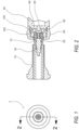
- Figs. 1 and 2 show a cross-sectional and front view, respectively, of one exemplary embodiment of the pressure airlock not according to the invention.
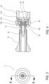
- Figs. 3 and 4 show a cross-sectional and front view, respectively, of an embodiment of the pressure airlock according to the invention.
- Fig. 5 shows a close-up of the pressure airlock shown in Fig. 1 .
- the pressure airlock includes a conduit 50 in fluid communication with the inflator or the gauge.
- the conduit 50 preferably permits the free flow of air between the inflator or gauge and the valve stem 10.
- the conduit 50, and indeed, the remaining operative "hard” portions of the pressure airlock may be formed of metal, plastic or any other durable material suitable for the described application.
- a tip 60 preferably extends from the conduit 50.
- the tip 60 includes a bore 70 that permits engagement with the valve stem 10.
- an O-ring 65 may be positioned between the tip 60 and the conduit 50.
- the bore 70 preferably corresponds in size with the exterior threads 20 of the valve stem 10 to create a tight engagement between the pressure airlock and the valve stem 10.
- the tip 60 may be integrated into the conduit 50 as a unitary component without the O-ring 65.
- a core depressor 80 is positioned within the bore 70.
- the core depressor 80 is preferably configured to engage with the valve core 30 of the valve stem 10 to permit inflation into the tire and/or permit a pressure reading from the tire.
- the core depressor 80 includes a diameter larger than a diameter of the corresponding valve core 30.
- an inner shoulder 90 surrounds the core depressor 80.
- the core depressor 80 extends beyond the inner shoulder 90 and toward the bore 70.
- the core depressor 80 is a suitable length so as the face 15 of the valve stem 10 is flush with the seal 150 before engagement of the core depressor 80 with the valve core 30, as shown in Fig. 1 and 5 . In this manner, a seal is formed between the seal 150 and the face 15 of the valve stem 10 before air is exchanged between the pressure airlock 5 and the valve stem 10. In this way, the "hissing" noise typically associated with filling or testing tires is avoided.
- An outer shoulder 100 extends from the inner shoulder 90 to create a stepped configuration within the pressure airlock.
- the outer shoulder 100 preferably extends beyond the core depressor 80.
- a seal 150 is positioned on the inner shoulder 90 and the outer shoulder 100 and extends within the tip 60.
- the tip 60 is positioned at an end of the pressure airlock and preferably forms a cavity between the outer shoulder 100 and an inner surface of the tip 60. As such, this cavity is preferably occupied, in part, by the seal 150.
- the seal 150 preferably abuts a face 15 of the valve stem 10 and the exterior threads 20 when in an engaged position. In this manner, the pressure airlock will create a primary seal around the exterior threads 20 of the valve stem 10 prior to the valve core 30 being depressed, as well as a face seal on the face of the valve stem 10. This combination results in a better user experience, in which the valve core 30 can be depressed and the user will not have to maintain constant pressure on the gauge or inflator to make the seal.
- the pressure airlock may include a single piece seal 150.
- the seal 150 may be rubber, foam or any similar pliable material that creates a flexible airtight seal between surfaces.
- the pressure airlock includes a two piece seal 150.
- a first piece 155 is positioned on the inner shoulder 90 and a second piece 160 is positioned on the outer shoulder 100.
- the first piece 155 may include different physical properties from the second piece 160, such as a different hardness, a different color, or other distinguishing characteristics that may be advantageous to a user.
Landscapes
- Engineering & Computer Science (AREA)
- General Engineering & Computer Science (AREA)
- Mechanical Engineering (AREA)
- Check Valves (AREA)
Description
- The invention relates to a pressure airlock for a gauge or an inflator.
- A typical interface in a gauge or inflator in the prior art includes a face seal within the valve interface to seal against the valve stem. The seal is easily broken or not maintained when the valve face does not make consistent planar contact with the seal, causing escaping air. The escaping ("hissing") air can lead to inaccurate pressure readings, inefficient inflation and/or customer confusion on proper product use and/or function.
US2014/190576A1 relates to a horizontally-triggerable inflation connector.US20170276278A1 relates to an attachment for an air valve. - The invention is defined in the appended claims. A pressure airlock may include one of two configurations. In a first configuration not according to the invention, a single (one piece) seal is formed in such a manner that when a valve stem enters the seal, the seal will make contact with the threads of the valve stem, creating a sealing area, and as the valve stem continues to move deeper into the seal, it will make contact with a perpendicular surface of the seal positioned on an inner shoulder of the pressure airlock. This creates a seal on the end or face of the valve stem as well. The combination of these sealing areas defines the pressure airlock as described. In this manner, the "hissing" of a typical such engagement is avoided.
- In an alternative configuration according to the invention, a combination of two separate seals is used to accomplish the same sealing arrangement as noted in the first configuration. The two seals preferably perform the same function as a one-piece seal but would permit different seal hardness options for optimum user "feel" during product usage. In addition, or alternatively, two different seals would permit use of different colors and/or other different properties.
- The above-mentioned and other features and objects of this invention will be better understood from the following detailed description taken in conjunction with the drawings wherein:
-
Fig. 1 is a front view of a Pressure Airlock Pressure Airlock, according to one exemplary embodiment not according to the invention; -
Fig. 2 is is a cross-sectional side view of the Pressure Airlock shown inFig. 1 taken along section 2-2; -
Fig. 3 is a front view of a Pressure Airlock Pressure Airlock, according to an embodiment of this invention; -
Fig. 4 is is a cross-sectional side view of the Pressure Airlock shown inFig. 3 taken along section 4-4; and -
Fig. 5 is a close-up cross-sectional side view of the Pressure Airlock embodiment shown inFig. 1 . -
Figs. 1-5 show a pressure airlock 5. The pressure airlock is preferably for use in connection with an inflator for inflating a standard pneumatic valve or a tire gauge for determining an air pressure from a standard pneumatic valve. A standard pneumatic valve as described herein preferably includes avalve stem 10 havingexterior threads 20 and avalve core 30 that, when depressed, permits the ingress or egress of air into the tire or inflated object. Although the term "tire" is generally used herein to described the inflated object, the subject invention may be used in connection with any inflated object that includes aconventional valve stem 10. -
Figs. 1 and 2 show a cross-sectional and front view, respectively, of one exemplary embodiment of the pressure airlock not according to the invention.Figs. 3 and 4 show a cross-sectional and front view, respectively, of an embodiment of the pressure airlock according to the invention.Fig. 5 shows a close-up of the pressure airlock shown inFig. 1 . - As best shown in
Fig 5 , the pressure airlock includes aconduit 50 in fluid communication with the inflator or the gauge. Theconduit 50 preferably permits the free flow of air between the inflator or gauge and thevalve stem 10. Theconduit 50, and indeed, the remaining operative "hard" portions of the pressure airlock may be formed of metal, plastic or any other durable material suitable for the described application. - A
tip 60 preferably extends from theconduit 50. Thetip 60 includes abore 70 that permits engagement with thevalve stem 10. As shown in the figures, an O-ring 65 may be positioned between thetip 60 and theconduit 50. Thebore 70 preferably corresponds in size with theexterior threads 20 of thevalve stem 10 to create a tight engagement between the pressure airlock and thevalve stem 10. Alternatively, thetip 60 may be integrated into theconduit 50 as a unitary component without the O-ring 65. - A
core depressor 80 is positioned within thebore 70. Thecore depressor 80 is preferably configured to engage with thevalve core 30 of thevalve stem 10 to permit inflation into the tire and/or permit a pressure reading from the tire. According to one embodiment, thecore depressor 80 includes a diameter larger than a diameter of thecorresponding valve core 30. - As shown in the figures, an
inner shoulder 90 surrounds thecore depressor 80. In one embodiment, thecore depressor 80 extends beyond theinner shoulder 90 and toward thebore 70. In a preferred embodiment of the invention, thecore depressor 80 is a suitable length so as theface 15 of thevalve stem 10 is flush with theseal 150 before engagement of thecore depressor 80 with thevalve core 30, as shown inFig. 1 and5 . In this manner, a seal is formed between theseal 150 and theface 15 of thevalve stem 10 before air is exchanged between the pressure airlock 5 and thevalve stem 10. In this way, the "hissing" noise typically associated with filling or testing tires is avoided. - An
outer shoulder 100 extends from theinner shoulder 90 to create a stepped configuration within the pressure airlock. Theouter shoulder 100 preferably extends beyond thecore depressor 80. - A
seal 150 is positioned on theinner shoulder 90 and theouter shoulder 100 and extends within thetip 60. As described above, thetip 60 is positioned at an end of the pressure airlock and preferably forms a cavity between theouter shoulder 100 and an inner surface of thetip 60. As such, this cavity is preferably occupied, in part, by theseal 150. - The
seal 150 preferably abuts aface 15 of thevalve stem 10 and theexterior threads 20 when in an engaged position. In this manner, the pressure airlock will create a primary seal around theexterior threads 20 of thevalve stem 10 prior to thevalve core 30 being depressed, as well as a face seal on the face of thevalve stem 10. This combination results in a better user experience, in which thevalve core 30 can be depressed and the user will not have to maintain constant pressure on the gauge or inflator to make the seal. - As shown in
Figs 1, 2 and5 , the pressure airlock may include asingle piece seal 150. Theseal 150 may be rubber, foam or any similar pliable material that creates a flexible airtight seal between surfaces. - As shown in
Figs. 3 and 4 , the pressure airlock includes a twopiece seal 150. As best shown inFig. 3 , afirst piece 155 is positioned on theinner shoulder 90 and asecond piece 160 is positioned on theouter shoulder 100. Thefirst piece 155 may include different physical properties from thesecond piece 160, such as a different hardness, a different color, or other distinguishing characteristics that may be advantageous to a user.
Claims (10)
- A pressure airlock for an inflator or a gauge for use with a valve stem (10) having exterior threads (20) and a valve core (30), the pressure airlock comprising:a conduit (50) in fluid communication with the inflator or the gauge;a tip (60) extending from the conduit (50), the tip having a bore (70);a core depressor (80) positioned within the bore;an inner shoulder (90) surrounding the core depressor (80), the core depressor extending beyond the inner shoulder;an outer shoulder (100) extending from the inner shoulder, the outer shoulder extending beyond the core depressor;a seal (150) positioned on the inner shoulder and the outer shoulder and extending within the tip;wherein the seal comprises a two piece seal, a first piece (155) positioned on the inner shoulder and a second piece (160) positioned on the outer shoulder;wherein the first piece (155) and the second piece (160) of the seal have a different hardness.
- The pressure airlock of Claim 1 wherein the first piece (155) includes different physical properties from the second piece (160).
- The pressure airlock of Claim 2 wherein the first piece (155) includes a different color from the second piece (160).
- The pressure airlock of Claim 1 wherein the core depressor (80) has a diameter larger than a diameter of the valve core (30).
- The pressure airlock of Claim 1 wherein an O-ring (65) is positioned between the tip (60) and the conduit (50).
- The pressure airlock of Claim 1 wherein the tip (60) forms a cavity between the outer shoulder (100) and an inner surface of the tip.
- The pressure airlock of Claim 1 wherein the seal (150) abuts a face of the valve stem (10) and the threads (20) when in an engaged position.
- The pressure airlock of Claim 1 wherein the bore (70) corresponds in size with the exterior threads (20) of the valve stem (10).
- The pressure airlock of claim 1 wherein the core depressor (80) has a larger diameter than the valve core (30).
- The pressure airlock of Claim 9 wherein the core depressor (80) extends beyond the inner shoulder (90).
Applications Claiming Priority (3)
| Application Number | Priority Date | Filing Date | Title |
|---|---|---|---|
| US201862754277P | 2018-11-01 | 2018-11-01 | |
| US16/669,080 US11293565B2 (en) | 2018-11-01 | 2019-10-30 | Pressure airlock |
| PCT/US2019/059187 WO2020092785A1 (en) | 2018-11-01 | 2019-10-31 | Pressure airlock |
Publications (2)
| Publication Number | Publication Date |
|---|---|
| EP3874193A1 EP3874193A1 (en) | 2021-09-08 |
| EP3874193B1 true EP3874193B1 (en) | 2023-04-05 |
Family
ID=70458053
Family Applications (1)
| Application Number | Title | Priority Date | Filing Date |
|---|---|---|---|
| EP19809258.7A Active EP3874193B1 (en) | 2018-11-01 | 2019-10-31 | Pressure airlock |
Country Status (4)
| Country | Link |
|---|---|
| US (1) | US11293565B2 (en) |
| EP (1) | EP3874193B1 (en) |
| CN (1) | CN113383187B (en) |
| WO (1) | WO2020092785A1 (en) |
Family Cites Families (21)
| Publication number | Priority date | Publication date | Assignee | Title |
|---|---|---|---|---|
| US7520292B2 (en) * | 2005-05-17 | 2009-04-21 | Brian Weltman | Pressure activated trap primer and water hammer combination |
| US7284419B2 (en) | 2005-05-25 | 2007-10-23 | Rutherford Robert B | Temporary attachment tire pressure gauge |
| TWI257903B (en) | 2005-08-31 | 2006-07-11 | Teng-Wen Huang | Tire pressure detector |
| TWM318073U (en) * | 2007-03-30 | 2007-09-01 | Lo-Pin Wang | Air outlet of an inflator |
| TW201026525A (en) | 2009-01-09 | 2010-07-16 | Teng-Wen Huang | Leakage prevention tire pressure detector |
| US8156955B2 (en) | 2009-09-10 | 2012-04-17 | Wei-Chi Wang | Inflating nozzle assembly |
| US8245722B2 (en) * | 2009-11-24 | 2012-08-21 | Ying-Che Huang | Inflation nozzle capable of connecting with two types of tire valves |
| ES2528134T3 (en) | 2010-08-23 | 2015-02-04 | Equalaire Systems, Inc. | Valve stem with auxiliary hole |
| TW201213169A (en) | 2010-09-30 | 2012-04-01 | Beto Engineering & Marketing | Dual use valve head for Schrader valve and Presta valve |
| US8360090B2 (en) | 2011-02-14 | 2013-01-29 | Beto Engineering and Marketing Co., Ltd. | Schrader valve/Presta valve dual-purpose valve cap |
| US9016304B2 (en) | 2013-01-07 | 2015-04-28 | Beto Engineering and Marketing Co., Ltd. | Horizontally-triggerable inflation connector |
| US8839809B1 (en) * | 2013-03-14 | 2014-09-23 | Beto Engineering & Marketing Co., Ltd. | Attachment for different air valves |
| US9133970B2 (en) * | 2013-08-21 | 2015-09-15 | Beto Entineering & Marketing Co., Ltd. | Attachment for different air valves |
| TWM491730U (en) | 2014-08-28 | 2014-12-11 | Jiao Hsiung Industry Corp | Air gun and air nozzle connector thereof |
| JP6163148B2 (en) | 2014-11-20 | 2017-07-12 | 長野計器株式会社 | Pressure sensor |
| EP3227129B1 (en) | 2014-12-04 | 2018-10-03 | Dana Heavy Vehicle Systems Group, LLC | Tire pressure management system |
| EP3253600A1 (en) | 2015-02-06 | 2017-12-13 | Dana Heavy Vehicle Systems Group, LLC | Assembly for a tire inflation system and the tire inflation system made therewith |
| US20170023163A1 (en) * | 2015-07-20 | 2017-01-26 | Norma U.S. Holding Llc | Heated Connector Assembly |
| US9989180B2 (en) | 2016-03-22 | 2018-06-05 | Beto Engineering & Marketing Co. Ltd. | Attachment for air valve |
| US9989179B2 (en) | 2016-03-22 | 2018-06-05 | Beto Engineering & Marketing Co., Ltd. | Attachment for different air valve |
| CN106621130B (en) * | 2016-11-16 | 2019-03-29 | 浙江欧伦泰防火设备有限公司 | Low pressure valve release and installation method |
-
2019
- 2019-10-30 US US16/669,080 patent/US11293565B2/en active Active
- 2019-10-31 CN CN201980071746.2A patent/CN113383187B/en active Active
- 2019-10-31 WO PCT/US2019/059187 patent/WO2020092785A1/en not_active Ceased
- 2019-10-31 EP EP19809258.7A patent/EP3874193B1/en active Active
Also Published As
| Publication number | Publication date |
|---|---|
| WO2020092785A1 (en) | 2020-05-07 |
| CN113383187A (en) | 2021-09-10 |
| US20200141516A1 (en) | 2020-05-07 |
| US11293565B2 (en) | 2022-04-05 |
| EP3874193A1 (en) | 2021-09-08 |
| CN113383187B (en) | 2023-03-24 |
Similar Documents
| Publication | Publication Date | Title |
|---|---|---|
| EP2995921B1 (en) | Pen-type pressure indicator for air compressor | |
| US8360090B2 (en) | Schrader valve/Presta valve dual-purpose valve cap | |
| US8015864B2 (en) | Digital tire pressure gauge with bleed valve | |
| US3450147A (en) | Pressure-limiting device for tires | |
| CN103703352B (en) | Pressure indicator | |
| US8245722B2 (en) | Inflation nozzle capable of connecting with two types of tire valves | |
| US9108474B2 (en) | Relief-valve device for an air pressure gauge | |
| US10703149B2 (en) | Air valve for tubeless pneumatic tire | |
| US20200079162A1 (en) | Replacement Valve Stem Assembly | |
| CN110892183A (en) | Improved tyre inflation valve | |
| CN113008445A (en) | Pressure gauge with multistage safety pressure relief | |
| CN100374766C (en) | Air flow control device | |
| EP3874193B1 (en) | Pressure airlock | |
| US1487851A (en) | Inflation device | |
| EP2390502A1 (en) | Inflation nozzle capable of connecting with two types of tire valves | |
| US7009505B2 (en) | Tire pressure gauge | |
| US20100171361A1 (en) | Tyre Valve | |
| US20060272707A1 (en) | Valve device for an inflatable object | |
| US20030144096A1 (en) | Inflatable device | |
| CN104422557B (en) | Pressure relief valve assembly for pressure gauges | |
| CN218325237U (en) | Inflator with built-in pressure gauge | |
| JP5779667B2 (en) | Pressure relief valve | |
| EP4314747B1 (en) | Pressure gauge for an inflatable article | |
| US986672A (en) | Combination pressure-gage and pump connection for pneumatic tires. | |
| EP1522835A1 (en) | Tire pressure gauge |
Legal Events
| Date | Code | Title | Description |
|---|---|---|---|
| STAA | Information on the status of an ep patent application or granted ep patent |
Free format text: STATUS: UNKNOWN |
|
| STAA | Information on the status of an ep patent application or granted ep patent |
Free format text: STATUS: THE INTERNATIONAL PUBLICATION HAS BEEN MADE |
|
| PUAI | Public reference made under article 153(3) epc to a published international application that has entered the european phase |
Free format text: ORIGINAL CODE: 0009012 |
|
| STAA | Information on the status of an ep patent application or granted ep patent |
Free format text: STATUS: REQUEST FOR EXAMINATION WAS MADE |
|
| 17P | Request for examination filed |
Effective date: 20210415 |
|
| AK | Designated contracting states |
Kind code of ref document: A1 Designated state(s): AL AT BE BG CH CY CZ DE DK EE ES FI FR GB GR HR HU IE IS IT LI LT LU LV MC MK MT NL NO PL PT RO RS SE SI SK SM TR |
|
| DAV | Request for validation of the european patent (deleted) | ||
| DAX | Request for extension of the european patent (deleted) | ||
| STAA | Information on the status of an ep patent application or granted ep patent |
Free format text: STATUS: EXAMINATION IS IN PROGRESS |
|
| 17Q | First examination report despatched |
Effective date: 20220503 |
|
| REG | Reference to a national code |
Ref country code: DE Ref legal event code: R079 Ref document number: 602019027289 Country of ref document: DE Free format text: PREVIOUS MAIN CLASS: F16L0037350000 Ipc: B60C0029060000 |
|
| GRAP | Despatch of communication of intention to grant a patent |
Free format text: ORIGINAL CODE: EPIDOSNIGR1 |
|
| STAA | Information on the status of an ep patent application or granted ep patent |
Free format text: STATUS: GRANT OF PATENT IS INTENDED |
|
| RIC1 | Information provided on ipc code assigned before grant |
Ipc: F16L 37/35 20060101ALI20221027BHEP Ipc: B60C 29/06 20060101AFI20221027BHEP |
|
| INTG | Intention to grant announced |
Effective date: 20221118 |
|
| GRAS | Grant fee paid |
Free format text: ORIGINAL CODE: EPIDOSNIGR3 |
|
| GRAA | (expected) grant |
Free format text: ORIGINAL CODE: 0009210 |
|
| STAA | Information on the status of an ep patent application or granted ep patent |
Free format text: STATUS: THE PATENT HAS BEEN GRANTED |
|
| AK | Designated contracting states |
Kind code of ref document: B1 Designated state(s): AL AT BE BG CH CY CZ DE DK EE ES FI FR GB GR HR HU IE IS IT LI LT LU LV MC MK MT NL NO PL PT RO RS SE SI SK SM TR |
|
| REG | Reference to a national code |
Ref country code: GB Ref legal event code: FG4D |
|
| REG | Reference to a national code |
Ref country code: DE Ref legal event code: R096 Ref document number: 602019027289 Country of ref document: DE |
|
| REG | Reference to a national code |
Ref country code: CH Ref legal event code: EP |
|
| REG | Reference to a national code |
Ref country code: AT Ref legal event code: REF Ref document number: 1557965 Country of ref document: AT Kind code of ref document: T Effective date: 20230415 |
|
| REG | Reference to a national code |
Ref country code: IE Ref legal event code: FG4D |
|
| P01 | Opt-out of the competence of the unified patent court (upc) registered |
Effective date: 20230606 |
|
| REG | Reference to a national code |
Ref country code: LT Ref legal event code: MG9D |
|
| REG | Reference to a national code |
Ref country code: NL Ref legal event code: MP Effective date: 20230405 |
|
| REG | Reference to a national code |
Ref country code: AT Ref legal event code: MK05 Ref document number: 1557965 Country of ref document: AT Kind code of ref document: T Effective date: 20230405 |
|
| PG25 | Lapsed in a contracting state [announced via postgrant information from national office to epo] |
Ref country code: NL Free format text: LAPSE BECAUSE OF FAILURE TO SUBMIT A TRANSLATION OF THE DESCRIPTION OR TO PAY THE FEE WITHIN THE PRESCRIBED TIME-LIMIT Effective date: 20230405 |
|
| PG25 | Lapsed in a contracting state [announced via postgrant information from national office to epo] |
Ref country code: SE Free format text: LAPSE BECAUSE OF FAILURE TO SUBMIT A TRANSLATION OF THE DESCRIPTION OR TO PAY THE FEE WITHIN THE PRESCRIBED TIME-LIMIT Effective date: 20230405 Ref country code: PT Free format text: LAPSE BECAUSE OF FAILURE TO SUBMIT A TRANSLATION OF THE DESCRIPTION OR TO PAY THE FEE WITHIN THE PRESCRIBED TIME-LIMIT Effective date: 20230807 Ref country code: NO Free format text: LAPSE BECAUSE OF FAILURE TO SUBMIT A TRANSLATION OF THE DESCRIPTION OR TO PAY THE FEE WITHIN THE PRESCRIBED TIME-LIMIT Effective date: 20230705 Ref country code: ES Free format text: LAPSE BECAUSE OF FAILURE TO SUBMIT A TRANSLATION OF THE DESCRIPTION OR TO PAY THE FEE WITHIN THE PRESCRIBED TIME-LIMIT Effective date: 20230405 Ref country code: AT Free format text: LAPSE BECAUSE OF FAILURE TO SUBMIT A TRANSLATION OF THE DESCRIPTION OR TO PAY THE FEE WITHIN THE PRESCRIBED TIME-LIMIT Effective date: 20230405 |
|
| PG25 | Lapsed in a contracting state [announced via postgrant information from national office to epo] |
Ref country code: RS Free format text: LAPSE BECAUSE OF FAILURE TO SUBMIT A TRANSLATION OF THE DESCRIPTION OR TO PAY THE FEE WITHIN THE PRESCRIBED TIME-LIMIT Effective date: 20230405 Ref country code: PL Free format text: LAPSE BECAUSE OF FAILURE TO SUBMIT A TRANSLATION OF THE DESCRIPTION OR TO PAY THE FEE WITHIN THE PRESCRIBED TIME-LIMIT Effective date: 20230405 Ref country code: LV Free format text: LAPSE BECAUSE OF FAILURE TO SUBMIT A TRANSLATION OF THE DESCRIPTION OR TO PAY THE FEE WITHIN THE PRESCRIBED TIME-LIMIT Effective date: 20230405 Ref country code: LT Free format text: LAPSE BECAUSE OF FAILURE TO SUBMIT A TRANSLATION OF THE DESCRIPTION OR TO PAY THE FEE WITHIN THE PRESCRIBED TIME-LIMIT Effective date: 20230405 Ref country code: IS Free format text: LAPSE BECAUSE OF FAILURE TO SUBMIT A TRANSLATION OF THE DESCRIPTION OR TO PAY THE FEE WITHIN THE PRESCRIBED TIME-LIMIT Effective date: 20230805 Ref country code: HR Free format text: LAPSE BECAUSE OF FAILURE TO SUBMIT A TRANSLATION OF THE DESCRIPTION OR TO PAY THE FEE WITHIN THE PRESCRIBED TIME-LIMIT Effective date: 20230405 Ref country code: GR Free format text: LAPSE BECAUSE OF FAILURE TO SUBMIT A TRANSLATION OF THE DESCRIPTION OR TO PAY THE FEE WITHIN THE PRESCRIBED TIME-LIMIT Effective date: 20230706 Ref country code: AL Free format text: LAPSE BECAUSE OF FAILURE TO SUBMIT A TRANSLATION OF THE DESCRIPTION OR TO PAY THE FEE WITHIN THE PRESCRIBED TIME-LIMIT Effective date: 20230405 |
|
| PG25 | Lapsed in a contracting state [announced via postgrant information from national office to epo] |
Ref country code: FI Free format text: LAPSE BECAUSE OF FAILURE TO SUBMIT A TRANSLATION OF THE DESCRIPTION OR TO PAY THE FEE WITHIN THE PRESCRIBED TIME-LIMIT Effective date: 20230405 |
|
| REG | Reference to a national code |
Ref country code: DE Ref legal event code: R097 Ref document number: 602019027289 Country of ref document: DE |
|
| PG25 | Lapsed in a contracting state [announced via postgrant information from national office to epo] |
Ref country code: SK Free format text: LAPSE BECAUSE OF FAILURE TO SUBMIT A TRANSLATION OF THE DESCRIPTION OR TO PAY THE FEE WITHIN THE PRESCRIBED TIME-LIMIT Effective date: 20230405 |
|
| PG25 | Lapsed in a contracting state [announced via postgrant information from national office to epo] |
Ref country code: SM Free format text: LAPSE BECAUSE OF FAILURE TO SUBMIT A TRANSLATION OF THE DESCRIPTION OR TO PAY THE FEE WITHIN THE PRESCRIBED TIME-LIMIT Effective date: 20230405 Ref country code: SK Free format text: LAPSE BECAUSE OF FAILURE TO SUBMIT A TRANSLATION OF THE DESCRIPTION OR TO PAY THE FEE WITHIN THE PRESCRIBED TIME-LIMIT Effective date: 20230405 Ref country code: RO Free format text: LAPSE BECAUSE OF FAILURE TO SUBMIT A TRANSLATION OF THE DESCRIPTION OR TO PAY THE FEE WITHIN THE PRESCRIBED TIME-LIMIT Effective date: 20230405 Ref country code: EE Free format text: LAPSE BECAUSE OF FAILURE TO SUBMIT A TRANSLATION OF THE DESCRIPTION OR TO PAY THE FEE WITHIN THE PRESCRIBED TIME-LIMIT Effective date: 20230405 Ref country code: DK Free format text: LAPSE BECAUSE OF FAILURE TO SUBMIT A TRANSLATION OF THE DESCRIPTION OR TO PAY THE FEE WITHIN THE PRESCRIBED TIME-LIMIT Effective date: 20230405 Ref country code: CZ Free format text: LAPSE BECAUSE OF FAILURE TO SUBMIT A TRANSLATION OF THE DESCRIPTION OR TO PAY THE FEE WITHIN THE PRESCRIBED TIME-LIMIT Effective date: 20230405 |
|
| PLBE | No opposition filed within time limit |
Free format text: ORIGINAL CODE: 0009261 |
|
| STAA | Information on the status of an ep patent application or granted ep patent |
Free format text: STATUS: NO OPPOSITION FILED WITHIN TIME LIMIT |
|
| 26N | No opposition filed |
Effective date: 20240108 |
|
| PG25 | Lapsed in a contracting state [announced via postgrant information from national office to epo] |
Ref country code: SI Free format text: LAPSE BECAUSE OF FAILURE TO SUBMIT A TRANSLATION OF THE DESCRIPTION OR TO PAY THE FEE WITHIN THE PRESCRIBED TIME-LIMIT Effective date: 20230405 |
|
| PG25 | Lapsed in a contracting state [announced via postgrant information from national office to epo] |
Ref country code: SI Free format text: LAPSE BECAUSE OF FAILURE TO SUBMIT A TRANSLATION OF THE DESCRIPTION OR TO PAY THE FEE WITHIN THE PRESCRIBED TIME-LIMIT Effective date: 20230405 Ref country code: IT Free format text: LAPSE BECAUSE OF FAILURE TO SUBMIT A TRANSLATION OF THE DESCRIPTION OR TO PAY THE FEE WITHIN THE PRESCRIBED TIME-LIMIT Effective date: 20230405 Ref country code: MC Free format text: LAPSE BECAUSE OF FAILURE TO SUBMIT A TRANSLATION OF THE DESCRIPTION OR TO PAY THE FEE WITHIN THE PRESCRIBED TIME-LIMIT Effective date: 20230405 |
|
| REG | Reference to a national code |
Ref country code: CH Ref legal event code: PL |
|
| REG | Reference to a national code |
Ref country code: BE Ref legal event code: MM Effective date: 20231031 |
|
| PG25 | Lapsed in a contracting state [announced via postgrant information from national office to epo] |
Ref country code: LU Free format text: LAPSE BECAUSE OF NON-PAYMENT OF DUE FEES Effective date: 20231031 |
|
| GBPC | Gb: european patent ceased through non-payment of renewal fee |
Effective date: 20231031 |
|
| PG25 | Lapsed in a contracting state [announced via postgrant information from national office to epo] |
Ref country code: LU Free format text: LAPSE BECAUSE OF NON-PAYMENT OF DUE FEES Effective date: 20231031 |
|
| PG25 | Lapsed in a contracting state [announced via postgrant information from national office to epo] |
Ref country code: GB Free format text: LAPSE BECAUSE OF NON-PAYMENT OF DUE FEES Effective date: 20231031 |
|
| PG25 | Lapsed in a contracting state [announced via postgrant information from national office to epo] |
Ref country code: CH Free format text: LAPSE BECAUSE OF NON-PAYMENT OF DUE FEES Effective date: 20231031 |
|
| PG25 | Lapsed in a contracting state [announced via postgrant information from national office to epo] |
Ref country code: GB Free format text: LAPSE BECAUSE OF NON-PAYMENT OF DUE FEES Effective date: 20231031 Ref country code: FR Free format text: LAPSE BECAUSE OF NON-PAYMENT OF DUE FEES Effective date: 20231031 Ref country code: CH Free format text: LAPSE BECAUSE OF NON-PAYMENT OF DUE FEES Effective date: 20231031 |
|
| PG25 | Lapsed in a contracting state [announced via postgrant information from national office to epo] |
Ref country code: BE Free format text: LAPSE BECAUSE OF NON-PAYMENT OF DUE FEES Effective date: 20231031 |
|
| PG25 | Lapsed in a contracting state [announced via postgrant information from national office to epo] |
Ref country code: IE Free format text: LAPSE BECAUSE OF NON-PAYMENT OF DUE FEES Effective date: 20231031 |
|
| PG25 | Lapsed in a contracting state [announced via postgrant information from national office to epo] |
Ref country code: IE Free format text: LAPSE BECAUSE OF NON-PAYMENT OF DUE FEES Effective date: 20231031 |
|
| PG25 | Lapsed in a contracting state [announced via postgrant information from national office to epo] |
Ref country code: BG Free format text: LAPSE BECAUSE OF FAILURE TO SUBMIT A TRANSLATION OF THE DESCRIPTION OR TO PAY THE FEE WITHIN THE PRESCRIBED TIME-LIMIT Effective date: 20230405 |
|
| PG25 | Lapsed in a contracting state [announced via postgrant information from national office to epo] |
Ref country code: BG Free format text: LAPSE BECAUSE OF FAILURE TO SUBMIT A TRANSLATION OF THE DESCRIPTION OR TO PAY THE FEE WITHIN THE PRESCRIBED TIME-LIMIT Effective date: 20230405 |
|
| PG25 | Lapsed in a contracting state [announced via postgrant information from national office to epo] |
Ref country code: CY Free format text: LAPSE BECAUSE OF FAILURE TO SUBMIT A TRANSLATION OF THE DESCRIPTION OR TO PAY THE FEE WITHIN THE PRESCRIBED TIME-LIMIT; INVALID AB INITIO Effective date: 20191031 |
|
| PG25 | Lapsed in a contracting state [announced via postgrant information from national office to epo] |
Ref country code: HU Free format text: LAPSE BECAUSE OF FAILURE TO SUBMIT A TRANSLATION OF THE DESCRIPTION OR TO PAY THE FEE WITHIN THE PRESCRIBED TIME-LIMIT; INVALID AB INITIO Effective date: 20191031 |
|
| PG25 | Lapsed in a contracting state [announced via postgrant information from national office to epo] |
Ref country code: TR Free format text: LAPSE BECAUSE OF FAILURE TO SUBMIT A TRANSLATION OF THE DESCRIPTION OR TO PAY THE FEE WITHIN THE PRESCRIBED TIME-LIMIT Effective date: 20230405 |
|
| PGFP | Annual fee paid to national office [announced via postgrant information from national office to epo] |
Ref country code: DE Payment date: 20251029 Year of fee payment: 7 |