EP3874138B1 - Injector with injector elements in circumferential rows with counter-clockwise and clockwise swirl - Google Patents
Injector with injector elements in circumferential rows with counter-clockwise and clockwise swirl Download PDFInfo
- Publication number
- EP3874138B1 EP3874138B1 EP18801235.5A EP18801235A EP3874138B1 EP 3874138 B1 EP3874138 B1 EP 3874138B1 EP 18801235 A EP18801235 A EP 18801235A EP 3874138 B1 EP3874138 B1 EP 3874138B1
- Authority
- EP
- European Patent Office
- Prior art keywords
- injector
- clockwise direction
- tube
- circumferential rows
- counter
- Prior art date
- Legal status (The legal status is an assumption and is not a legal conclusion. Google has not performed a legal analysis and makes no representation as to the accuracy of the status listed.)
- Active
Links
Images

Classifications
-
- F—MECHANICAL ENGINEERING; LIGHTING; HEATING; WEAPONS; BLASTING
- F02—COMBUSTION ENGINES; HOT-GAS OR COMBUSTION-PRODUCT ENGINE PLANTS
- F02K—JET-PROPULSION PLANTS
- F02K9/00—Rocket-engine plants, i.e. plants carrying both fuel and oxidant therefor; Control thereof
- F02K9/42—Rocket-engine plants, i.e. plants carrying both fuel and oxidant therefor; Control thereof using liquid or gaseous propellants
- F02K9/44—Feeding propellants
- F02K9/52—Injectors
-
- F—MECHANICAL ENGINEERING; LIGHTING; HEATING; WEAPONS; BLASTING
- F02—COMBUSTION ENGINES; HOT-GAS OR COMBUSTION-PRODUCT ENGINE PLANTS
- F02K—JET-PROPULSION PLANTS
- F02K9/00—Rocket-engine plants, i.e. plants carrying both fuel and oxidant therefor; Control thereof
- F02K9/42—Rocket-engine plants, i.e. plants carrying both fuel and oxidant therefor; Control thereof using liquid or gaseous propellants
- F02K9/60—Constructional parts; Details not otherwise provided for
-
- F—MECHANICAL ENGINEERING; LIGHTING; HEATING; WEAPONS; BLASTING
- F23—COMBUSTION APPARATUS; COMBUSTION PROCESSES
- F23R—GENERATING COMBUSTION PRODUCTS OF HIGH PRESSURE OR HIGH VELOCITY, e.g. GAS-TURBINE COMBUSTION CHAMBERS
- F23R3/00—Continuous combustion chambers using liquid or gaseous fuel
- F23R3/28—Continuous combustion chambers using liquid or gaseous fuel characterised by the fuel supply
- F23R3/34—Feeding into different combustion zones
-
- F—MECHANICAL ENGINEERING; LIGHTING; HEATING; WEAPONS; BLASTING
- F23—COMBUSTION APPARATUS; COMBUSTION PROCESSES
- F23R—GENERATING COMBUSTION PRODUCTS OF HIGH PRESSURE OR HIGH VELOCITY, e.g. GAS-TURBINE COMBUSTION CHAMBERS
- F23R3/00—Continuous combustion chambers using liquid or gaseous fuel
- F23R3/42—Continuous combustion chambers using liquid or gaseous fuel characterised by the arrangement or form of the flame tubes or combustion chambers
- F23R3/58—Cyclone or vortex type combustion chambers
-
- F—MECHANICAL ENGINEERING; LIGHTING; HEATING; WEAPONS; BLASTING
- F05—INDEXING SCHEMES RELATING TO ENGINES OR PUMPS IN VARIOUS SUBCLASSES OF CLASSES F01-F04
- F05D—INDEXING SCHEME FOR ASPECTS RELATING TO NON-POSITIVE-DISPLACEMENT MACHINES OR ENGINES, GAS-TURBINES OR JET-PROPULSION PLANTS
- F05D2240/00—Components
- F05D2240/40—Use of a multiplicity of similar components
-
- F—MECHANICAL ENGINEERING; LIGHTING; HEATING; WEAPONS; BLASTING
- F05—INDEXING SCHEMES RELATING TO ENGINES OR PUMPS IN VARIOUS SUBCLASSES OF CLASSES F01-F04
- F05D—INDEXING SCHEME FOR ASPECTS RELATING TO NON-POSITIVE-DISPLACEMENT MACHINES OR ENGINES, GAS-TURBINES OR JET-PROPULSION PLANTS
- F05D2250/00—Geometry
- F05D2250/30—Arrangement of components
- F05D2250/37—Arrangement of components circumferential
Definitions
- Liquid propellant rocket engines may be powered by a fuel propellant and an oxidizer propellant.
- the fuel and oxidizer are typically provided to an injector, which has a plurality of injector elements that introduce the propellants into a combustion chamber for combustion.
- the combustion products are then exhausted through a nozzle downstream of the combustion chamber to provide thrust.
- a prior art injector having the features of the preamble to claim 1 is disclosed in GB 1 289 934 .
- Other prior art injectors are disclosed in CN 103 867 340 and US 2004/050982 .
- the present invention provides an injector for a liquid rocket engine according to claim 1.
- each of the injector elements includes a first tube that provides the central passage and a second, outer tube situated at an end of the first tube so as to provide an annular space there between.
- the peripheral transverse passages extends through the second tube and opening to the annular space.
- peripheral transverse passages are provided in two circumferential rows around the second tube.
- the second tube extends beyond the end of the first tube to define a cup region between the end of the first tube and an end of the second tube.
- the group of circumferential rows that alternate between the counter-clockwise direction and the clockwise direction includes at least four circumferential rows.
- one of the injector elements is arranged as a single, center injector element and the circumferential rows are arranged concentrically about the single, center injector element.
- the present invention provides a liquid rocket engine according to claim 7.
- the nozzle is a converging-diverging nozzle.
- a further embodiment of any of the foregoing embodiments includes a fuel source and an oxidizer source.
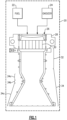
- Figure 1 schematically illustrates the thrust chamber of a liquid propellant rocket engine 20.
- the engine 20 will typically have plumbing for delivering fuel and oxidizer propellants, as well as pumps and valves for controlling propellant delivery.
- the engine 20 is operable to pump fuel (e.g., liquid hydrogen or liquid hydrocarbon) from a fuel source 22 and oxidizer (e.g., oxidizer-rich turbine exhaust hot gas) from an oxidizer source 24 to an injector 26.
- the injector 26 may generally include an injector housing 28 and injector elements 30 that are operable to introduce the fuel and oxidizer into a downstream combustion chamber 32 for combustion.
- the combustion chamber 32 is cylindrical and is formed of a metal alloy.
- the combustion products are then exhausted through a nozzle 34 to produce thrust.
- the nozzle 34 is a converging-diverging nozzle that includes a convergent section 34a, a throat section 34b, and a divergent section 34c.
- the nozzle 34 is attached to the combustion chamber 32, and the combustion chamber 32 is attached to the injector 30.
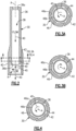
- FIG. 2 illustrates a representative one of the injector elements 30 of the injector 26.
- Each injector element 30 is disposed about a central axis A and includes a tube 36 that provides a central passage 38.
- the central passage 38 is configured to provide axial injection flow, as represented at 40, of the oxidizer gas.
- the tube 36 includes an inlet 36a at one end thereof and an outlet 36b at the opposite end thereof.
- the inlet 36a is connected to the oxidizer source 24.
- a second tube 42 which most typically is integral with the first tube 36, is provided at the second end of the first tube 36 and is coaxial therewith.
- the second tube 42 is diametrically larger than the first tube 36 and thus provides an annular space 44 between the outer diameter surface at the second end of the first tube 36 and the inner diameter surface of the second tube 42. Since the tubes are integral, or at least attached, the annular space 44 terminates at location 43.
- the second tube 42 extends beyond the second end of the first tube 36 and thereby defines a cup region R between the ends of the tubes 36 and 42.
- the second tube 42 includes a plurality of peripheral transverse passages 46.
- each passage 46 is linear and extends tangentially to the annular space 44 between the first tube 36 and the second tube 42.
- Each passage 46 includes an inlet 46a at or near the outer diameter surface of the second tube 42 and an outlet 46b that opens at the inner diameter surface of the second tube 42 to the annular space 44.
- the inlets 46a may be connected with channels or a manifold to deliver the fuel from the fuel source 22 thereto.
- the injector element 30 includes two circumferential rows of the passages 46.
- the tangential orientation of the passages 46 are configured to introduce flow of the fuel into the annular space 44 in a tangential direction, thereby producing a swirl injection flow of fuel around the annular space 44 and, eventually, around the axial injection flow 40 of the oxidizer in the cup region R from the first tube 36.
- the swirl injection flow represented at 45, can be in either a clockwise direction or a counter-clockwise direction when viewing the injector element 30 axially from the side of the combustion chamber 32.
- the passages 46 are oriented to provide the swirl injection flow in the counter-clockwise direction (exclusively) and thus represent an injector element 30 that is of the counter-clockwise direction.
- the injector element 30 for the clockwise direction is of the same construction as described above except that the passages 46 are oriented in the opposite direction.
- Figure 3B illustrates an example in which the passages 46 are oriented in the opposite direction to provide the swirl injection flow in the clockwise direction (exclusively).
- a portion of the injector elements 30 of the injector 26 can be configured with passages 46 to provide the swirl injection flow exclusively in the counter-clockwise direction, while other injector elements 30 can be configured to provide the swirl injection flow exclusively in the clockwise direction.
- Figure 5 illustrates a representative section of the injector 26 viewed from an axial direction from the top of the combustion chamber 32.
- a portion of the injector elements 30 are configured to provide the swirl injection flow in the counter-clockwise direction (e.g., Figure 3A ) and another portion of the injector elements 30 are configured to provide the swirl injection flow in the clockwise direction (e.g., Figure 3B ).
- the injector elements 30 within each individual row 48 are either all of the clockwise direction or all of the counter-clockwise direction.
- rows 48 that are of the clockwise direction are represented by a circular arrow designated "CW"
- rows 48 that are of the counter-clockwise direction are represented by a circular arrow designated "CCW.”
- a 60° wedge of the injector 26 is shown.
- the wedge represents a repeat unit of the injector 26 such that six identical wedges are assembled together to form the full circular configuration of the injector 26.
- the injector elements 30 can be seen on the back face of the injector 26.
- the injector elements 30 are arranged in an array with one, single injector element 30a at the center and then the circumferential rows 48 of the injector elements 30, represented as rows 48-1, 48-2, 48-3, 48-4, 48-5, 48-6, and 48-7 (collectively "rows 48").
- the injector elements 30 are generally uniformly spaced apart within the rows 48, and the rows 48 are concentric about the center injector element 30a.
- Figure 5 illustrates an example, outside the scope of the claims, with alternatively reversed swirl (ARS) between adjacent circumferential rows of the injector 26.
- ARS alternatively reversed swirl
- all of the circumferential rows 48-1, 48-2, 48-3, 48-4, 48-5, 48-6, and 48-7 are of alternating configuration between the clockwise direction and the counter-clockwise direction between adjacent rows.
- Other contemplated configurations include alternating only the two outermost circumferential rows, followed by consecutive rows that are all of either the clockwise direction or the counter-clockwise direction.
- the inverse patterns of the clockwise direction or the counter-clockwise direction is also contemplated.
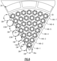
- Figure 6 illustrates an example, within the scope of the claims, with partial ARS (PARS).
- the center injector element 30a is of the clockwise direction, and is followed by, moving radially outward, at least two, but in this example three consecutive circumferential rows 148-1, 148-2, and 148-3 that are of the clockwise direction.
- the final outer four circumferential rows 148-4, 148-5, 148-6, and 148-7 alternate between the counter-clockwise direction and the clockwise direction between adjacent rows.
- the oxidizer maintains a relatively circular shape as it emanates from the injector into and along the combustion chamber.
- the cross-section of the oxidizer stream tends to be elongated in directions transverse to the central axes A of the injector elements 30, thereby increasing the surface area for faster mixing and burning, hence shortening the axial length of the oxidizer stream. Therefore, in the outermost rows, compared to the baseline injector, the shorter oxidizer streams of the ARS would not penetrate and break the fuel film cooling layer on the chamber wall as much, thus the occurrence of hot streaks at the combustor walls may be significantly reduced.
- the following comparative example between the ARS and PARS is based on the steady state reacting flow CFD solutions for the internal flow inside the thrust chamber assembly at the same condition.
- the partial ARS configurations have reverse swirl in three, two, or one even number rows. It was found that reversal in two rows has the best energy release efficiency (ERE), and very closely compared wall thermal condition.
- ERP energy release efficiency
- each injector element generates a stream tube, in which fuel stream and oxidizer stream are initial stratified but eventually mixed and burned, and to be mixed with the fluid outside these stream tubes.
- the ERE optimal comes because of the competing act between the in-stream tube mixing (ISTM) and between-stream tube mixing (BSTM).
- the ARS promotes ISTM, hence the thermal expansion that accelerates the fluid particles' axial motion, leading to less residence time for the BSTM.
Landscapes
- Engineering & Computer Science (AREA)
- Chemical & Material Sciences (AREA)
- Combustion & Propulsion (AREA)
- Mechanical Engineering (AREA)
- General Engineering & Computer Science (AREA)
- Nozzles (AREA)
- Fuel-Injection Apparatus (AREA)
- Testing Of Engines (AREA)
Description
- Liquid propellant rocket engines may be powered by a fuel propellant and an oxidizer propellant. The fuel and oxidizer are typically provided to an injector, which has a plurality of injector elements that introduce the propellants into a combustion chamber for combustion. The combustion products are then exhausted through a nozzle downstream of the combustion chamber to provide thrust.
- A prior art injector having the features of the preamble to claim 1 is disclosed in
GB 1 289 934 CN 103 867 340 andUS 2004/050982 . - From one aspect, the present invention provides an injector for a liquid rocket engine according to claim 1.
- In a further embodiment of any of the foregoing embodiments, each of the injector elements includes a first tube that provides the central passage and a second, outer tube situated at an end of the first tube so as to provide an annular space there between. The peripheral transverse passages extends through the second tube and opening to the annular space.
- In a further embodiment of any of the foregoing embodiments, the peripheral transverse passages are provided in two circumferential rows around the second tube.
- In a further embodiment of any of the foregoing embodiments, the second tube extends beyond the end of the first tube to define a cup region between the end of the first tube and an end of the second tube.
- In a further embodiment of any of the foregoing embodiments, the group of circumferential rows that alternate between the counter-clockwise direction and the clockwise direction includes at least four circumferential rows.
- In a further embodiment of any of the foregoing embodiments, one of the injector elements is arranged as a single, center injector element and the circumferential rows are arranged concentrically about the single, center injector element.
- From another aspect, the present invention provides a liquid rocket engine according to claim 7.
- In a further embodiment of any of the foregoing embodiments, the nozzle is a converging-diverging nozzle.
- A further embodiment of any of the foregoing embodiments includes a fuel source and an oxidizer source.
- The various features and advantages of the present disclosure will become apparent to those skilled in the art from the following detailed description. The drawings that accompany the detailed description can be briefly described as follows.
-
Figure 1 illustrates an example liquid rocket engine. -
Figure 2 illustrates a representative example of an injector element of an injector of the liquid rocket engine. -
Figure 3A illustrates a sectioned view of the injector ofFigure 2 for counterclockwise swirl. -
Figure 3B illustrates a sectioned view of an injector for clockwise swirl. -
Figure 4 illustrates another sectioned view of the injector element ofFigure 2 . -
Figure 5 illustrates a representative section of the injector in axial view that is outside the scope of the claims. -
Figure 6 illustrates another example of the representative section of an injector in axial view that is within the scope of the claims. -
Figure 1 schematically illustrates the thrust chamber of a liquidpropellant rocket engine 20. As will be appreciated, there are many different types of liquid propellant engines to which this disclosure may apply. In this regard, although not shown, theengine 20 will typically have plumbing for delivering fuel and oxidizer propellants, as well as pumps and valves for controlling propellant delivery. - In this example, the
engine 20 is operable to pump fuel (e.g., liquid hydrogen or liquid hydrocarbon) from afuel source 22 and oxidizer (e.g., oxidizer-rich turbine exhaust hot gas) from anoxidizer source 24 to aninjector 26. Theinjector 26 may generally include aninjector housing 28 andinjector elements 30 that are operable to introduce the fuel and oxidizer into adownstream combustion chamber 32 for combustion. For example, thecombustion chamber 32 is cylindrical and is formed of a metal alloy. The combustion products are then exhausted through anozzle 34 to produce thrust. In the example shown, thenozzle 34 is a converging-diverging nozzle that includes a convergent section 34a, a throat section 34b, and adivergent section 34c. Thenozzle 34 is attached to thecombustion chamber 32, and thecombustion chamber 32 is attached to theinjector 30. -
Figure 2 illustrates a representative one of theinjector elements 30 of theinjector 26. Eachinjector element 30 is disposed about a central axis A and includes atube 36 that provides acentral passage 38. Thecentral passage 38 is configured to provide axial injection flow, as represented at 40, of the oxidizer gas. In this regard, thetube 36 includes aninlet 36a at one end thereof and anoutlet 36b at the opposite end thereof. Theinlet 36a is connected to theoxidizer source 24. - A
second tube 42, which most typically is integral with thefirst tube 36, is provided at the second end of thefirst tube 36 and is coaxial therewith. Thesecond tube 42 is diametrically larger than thefirst tube 36 and thus provides anannular space 44 between the outer diameter surface at the second end of thefirst tube 36 and the inner diameter surface of thesecond tube 42. Since the tubes are integral, or at least attached, theannular space 44 terminates atlocation 43. Thesecond tube 42 extends beyond the second end of thefirst tube 36 and thereby defines a cup region R between the ends of thetubes - As shown in the sectioned views in
Figures 3A and 4 , thesecond tube 42 includes a plurality of peripheraltransverse passages 46. In this example, eachpassage 46 is linear and extends tangentially to theannular space 44 between thefirst tube 36 and thesecond tube 42. Eachpassage 46 includes aninlet 46a at or near the outer diameter surface of thesecond tube 42 and anoutlet 46b that opens at the inner diameter surface of thesecond tube 42 to theannular space 44. Theinlets 46a may be connected with channels or a manifold to deliver the fuel from thefuel source 22 thereto. - As represented in the cross-sections in
Figures 3A and 4 , theinjector element 30 includes two circumferential rows of thepassages 46. In this example, the tangential orientation of thepassages 46 are configured to introduce flow of the fuel into theannular space 44 in a tangential direction, thereby producing a swirl injection flow of fuel around theannular space 44 and, eventually, around theaxial injection flow 40 of the oxidizer in the cup region R from thefirst tube 36. Thus, depending on the slope orientation of thepassages 46, the swirl injection flow, represented at 45, can be in either a clockwise direction or a counter-clockwise direction when viewing theinjector element 30 axially from the side of thecombustion chamber 32. As shown inFigures 3A and 4 , thepassages 46 are oriented to provide the swirl injection flow in the counter-clockwise direction (exclusively) and thus represent aninjector element 30 that is of the counter-clockwise direction. - The
injector element 30 for the clockwise direction is of the same construction as described above except that thepassages 46 are oriented in the opposite direction.Figure 3B illustrates an example in which thepassages 46 are oriented in the opposite direction to provide the swirl injection flow in the clockwise direction (exclusively). - As will be described in further detail below, a portion of the
injector elements 30 of theinjector 26 can be configured withpassages 46 to provide the swirl injection flow exclusively in the counter-clockwise direction, whileother injector elements 30 can be configured to provide the swirl injection flow exclusively in the clockwise direction. -
Figure 5 illustrates a representative section of theinjector 26 viewed from an axial direction from the top of thecombustion chamber 32. In this example, which is outside the scope of the claims, a portion of theinjector elements 30 are configured to provide the swirl injection flow in the counter-clockwise direction (e.g.,Figure 3A ) and another portion of theinjector elements 30 are configured to provide the swirl injection flow in the clockwise direction (e.g.,Figure 3B ). For instance, theinjector elements 30 within eachindividual row 48 are either all of the clockwise direction or all of the counter-clockwise direction. In the example shown,rows 48 that are of the clockwise direction are represented by a circular arrow designated "CW" androws 48 that are of the counter-clockwise direction are represented by a circular arrow designated "CCW." - In this example, a 60° wedge of the
injector 26 is shown. The wedge represents a repeat unit of theinjector 26 such that six identical wedges are assembled together to form the full circular configuration of theinjector 26. As shown, theinjector elements 30 can be seen on the back face of theinjector 26. Theinjector elements 30 are arranged in an array with one,single injector element 30a at the center and then thecircumferential rows 48 of theinjector elements 30, represented as rows 48-1, 48-2, 48-3, 48-4, 48-5, 48-6, and 48-7 (collectively "rows 48"). Theinjector elements 30 are generally uniformly spaced apart within therows 48, and therows 48 are concentric about thecenter injector element 30a. -
Figure 5 illustrates an example, outside the scope of the claims, with alternatively reversed swirl (ARS) between adjacent circumferential rows of theinjector 26. In this example, all of the circumferential rows 48-1, 48-2, 48-3, 48-4, 48-5, 48-6, and 48-7 are of alternating configuration between the clockwise direction and the counter-clockwise direction between adjacent rows. Other contemplated configurations include alternating only the two outermost circumferential rows, followed by consecutive rows that are all of either the clockwise direction or the counter-clockwise direction. As will be appreciated, in any of the examples herein, the inverse patterns of the clockwise direction or the counter-clockwise direction is also contemplated. -
Figure 6 illustrates an example, within the scope of the claims, with partial ARS (PARS). In this example, thecenter injector element 30a is of the clockwise direction, and is followed by, moving radially outward, at least two, but in this example three consecutive circumferential rows 148-1, 148-2, and 148-3 that are of the clockwise direction. The final outer four circumferential rows 148-4, 148-5, 148-6, and 148-7 alternate between the counter-clockwise direction and the clockwise direction between adjacent rows. - The following comparative example between a baseline injector in which all of the injector elements swirl in the same direction and ARS is based on steady state reacting flow computational fluid dynamics (CFD) solutions for the internal flow inside the thrust chamber assembly (the combination of
injector 26,chamber 32 and nozzle 34) at high pressure conditions (typically around 3000 psi) fed with liquid fuel and oxidizer-rich turbine exhaust hot gas, which is at supercritical pressure conditions for both fuel and oxidizer. The fuel streams injected from each injector element tend to swirl around the central axial flow of the oxidizer. Between the adjacent circumferential rows of injector elements, the baseline injector has shearing interaction, whereas the ARS has tearing interaction. Under the shearing interaction, in cross-section, the oxidizer maintains a relatively circular shape as it emanates from the injector into and along the combustion chamber. Under the tearing interaction however, the cross-section of the oxidizer stream tends to be elongated in directions transverse to the central axes A of theinjector elements 30, thereby increasing the surface area for faster mixing and burning, hence shortening the axial length of the oxidizer stream. Therefore, in the outermost rows, compared to the baseline injector, the shorter oxidizer streams of the ARS would not penetrate and break the fuel film cooling layer on the chamber wall as much, thus the occurrence of hot streaks at the combustor walls may be significantly reduced. - The following comparative example between the ARS and PARS is based on the steady state reacting flow CFD solutions for the internal flow inside the thrust chamber assembly at the same condition. The partial ARS configurations have reverse swirl in three, two, or one even number rows. It was found that reversal in two rows has the best energy release efficiency (ERE), and very closely compared wall thermal condition. Consider that each injector element generates a stream tube, in which fuel stream and oxidizer stream are initial stratified but eventually mixed and burned, and to be mixed with the fluid outside these stream tubes. The ERE optimal comes because of the competing act between the in-stream tube mixing (ISTM) and between-stream tube mixing (BSTM). The ARS promotes ISTM, hence the thermal expansion that accelerates the fluid particles' axial motion, leading to less residence time for the BSTM.
- The scope of legal protection given to this disclosure can only be determined by studying the following claims.
Claims (9)
- An injector (26) for a liquid rocket engine (20), comprising:an array of injector elements (30), each injector element (30) includes a central passage (38) defining a central axis (A) and a plurality of peripheral transverse passages (46), the central passages (38) are configured to provide axial injection flow and the peripheral transverse passages (46) are configured to provide swirl injection flow about the axial injection flow, wherein a portion of the injector elements (30) are configured to provide the swirl injection flow in a clockwise direction and another portion of the injector elements (30) are configured to provide the swirl injection flow in a counter-clockwise direction, andthe injector elements (30) are arranged to form a plurality of circumferential rows (148), the injector elements (30) of each one of the circumferential rows (148) are either all of the clockwise direction or all of the counter-clockwise direction, and there is at least one circumferential row (148) of the clockwise direction and at least one circumferential row (148) of the counter-clockwise direction; and characterised in thatthe circumferential rows include a group of circumferential rows (148-4-148-7) that alternate between the counter-clockwise direction and the clockwise direction and at least two consecutive circumferential rows (148-1-148-3) that are either the clockwise direction or the counter-clockwise direction, wherein the at least two consecutive circumferential rows (148-1-148-3) are radially inward of the group of circumferential rows (148-4-148-7) that alternate.
- The injector as recited in claim 1, wherein each of the injector elements (30) includes a first tube (36) that provides the central passage (38) and a second, outer tube (42) situated at an end of the first tube (36) so as to provide an annular space (44) there between, the peripheral transverse passages (46) extending through the second tube (42) and opening to the annular space (44).
- The injector as recited in claim 2, wherein the peripheral transverse passages (46) are provided in two circumferential rows around the second tube (42).
- The injector as recited in claim 2 or 3, wherein the second tube (42) extends beyond the end of the first tube (36) to define a cup region (R) between the end of the first tube (36) and an end of the second tube (42).
- The injector as recited in any preceding claim, wherein the group of circumferential rows (148-4-148-7) that alternate between the counter-clockwise direction and the clockwise direction includes at least four circumferential rows (148-4-148-7).
- The injector as recited in any preceding claim, wherein one of the injector elements (30) is arranged as a single, center injector element (30a) and the circumferential rows (148) are arranged concentrically about the single, center injector element (30a).
- A liquid rocket engine (20) comprising:a combustion chamber (32);a nozzle (34) attached with the combustion chamber (32); andan injector (26) according to any preceding claim attached with the combustion chamber (32).
- The liquid rocket engine as recited in claim 7, wherein the nozzle (34) is a converging-diverging nozzle.
- The liquid rocket engine as recited in claim 7 or 8, further comprising a fuel source (22) and an oxidizer source (24).
Applications Claiming Priority (1)
| Application Number | Priority Date | Filing Date | Title |
|---|---|---|---|
| PCT/US2018/058128 WO2020091738A1 (en) | 2018-10-30 | 2018-10-30 | Injector with injector elements in circumferential rows that alternate between counter-clockwise and clockwise swirl |
Publications (3)
| Publication Number | Publication Date |
|---|---|
| EP3874138A1 EP3874138A1 (en) | 2021-09-08 |
| EP3874138B1 true EP3874138B1 (en) | 2024-03-13 |
| EP3874138B8 EP3874138B8 (en) | 2024-05-01 |
Family
ID=64277921
Family Applications (1)
| Application Number | Title | Priority Date | Filing Date |
|---|---|---|---|
| EP18801235.5A Active EP3874138B8 (en) | 2018-10-30 | 2018-10-30 | Injector with injector elements in circumferential rows with counter-clockwise and clockwise swirl |
Country Status (5)
| Country | Link |
|---|---|
| US (2) | US11846253B2 (en) |
| EP (1) | EP3874138B8 (en) |
| JP (1) | JP7185776B2 (en) |
| RU (1) | RU2765592C1 (en) |
| WO (1) | WO2020091738A1 (en) |
Families Citing this family (2)
| Publication number | Priority date | Publication date | Assignee | Title |
|---|---|---|---|---|
| CN113339159B (en) * | 2021-07-06 | 2022-08-16 | 西安航天动力研究所 | Coaxial double-centrifugal injector based on 3D printing and liquid oxygen kerosene rocket engine |
| KR102838971B1 (en) * | 2023-03-28 | 2025-07-25 | 충북대학교 산학협력단 | coaxial swirl injection device for small rocket thrusters |
Family Cites Families (22)
| Publication number | Priority date | Publication date | Assignee | Title |
|---|---|---|---|---|
| US3468487A (en) * | 1966-02-28 | 1969-09-23 | Us Navy | Variable thrust injector |
| GB1289934A (en) | 1971-02-24 | 1972-09-20 | ||
| US4116383A (en) * | 1977-02-10 | 1978-09-26 | United Technologies Corporation | Method and apparatus for mixing fluid |
| DE3328973A1 (en) * | 1983-08-11 | 1985-02-21 | Messerschmitt-Bölkow-Blohm GmbH, 8012 Ottobrunn | Injection nozzles for injection heads of combustion chambers for rocket engines |
| US4971768A (en) * | 1987-11-23 | 1990-11-20 | United Technologies Corporation | Diffuser with convoluted vortex generator |
| US5172548A (en) * | 1988-09-14 | 1992-12-22 | Societe Europeene De Propulsion | Device for tapping off hot gases from a combustion chamber and injector head equipped with such a device |
| US4991398A (en) * | 1989-01-12 | 1991-02-12 | United Technologies Corporation | Combustor fuel nozzle arrangement |
| FR2712030B1 (en) * | 1993-11-03 | 1996-01-26 | Europ Propulsion | Injection system and associated tricoaxial injection elements. |
| GB2319078B (en) * | 1996-11-08 | 1999-11-03 | Europ Gas Turbines Ltd | Combustor arrangement |
| RU2158841C2 (en) * | 1999-01-21 | 2000-11-10 | Открытое акционерное общество "НПО Энергомаш им. акад. В.П. Глушко" | Liquid-propellant thrust chamber and its casing |
| RU2159351C1 (en) | 1999-03-01 | 2000-11-20 | Открытое акционерное общество НПО Энергомаш им. акад. В.П. Глушко | Gas generator |
| US6351939B1 (en) * | 2000-04-21 | 2002-03-05 | The Boeing Company | Swirling, impinging sheet injector |
| US6755359B2 (en) * | 2002-09-12 | 2004-06-29 | The Boeing Company | Fluid mixing injector and method |
| US7124574B2 (en) * | 2002-12-04 | 2006-10-24 | United Technologies Corporation | Method and apparatus for a substantially coaxial injector element |
| US6918243B2 (en) * | 2003-05-19 | 2005-07-19 | The Boeing Company | Bi-propellant injector with flame-holding zone igniter |
| JP4287349B2 (en) * | 2004-09-30 | 2009-07-01 | 三菱重工業株式会社 | Rocket injector |
| JP4100518B2 (en) * | 2005-04-18 | 2008-06-11 | 独立行政法人 宇宙航空研究開発機構 | Pintle injector |
| US9500368B2 (en) * | 2008-09-23 | 2016-11-22 | Siemens Energy, Inc. | Alternately swirling mains in lean premixed gas turbine combustors |
| CN103867340B (en) | 2012-12-12 | 2017-07-25 | 中国人民解放军国防科学技术大学 | A double swirl injector |
| RU2535596C1 (en) * | 2013-05-06 | 2014-12-20 | Федеральное государственное унитарное предприятие "Государственный космический научно-производственный центр имени М.В. Хруничева" | Method of organising of working process in combustion chamber of low thrust liquid fuel rocket motor |
| FR3033365B1 (en) * | 2015-03-05 | 2017-03-31 | Snecma | IMPROVED ERGOL INJECTOR FOR ERGOL COLLECTION WITH HOMOGENEOUS INJECTION |
| RU2591391C1 (en) * | 2015-06-29 | 2016-07-20 | Федеральное государственное автономное образовательное учреждение высшего образования "Национальный исследовательский Томский государственный университет" (ТГУ) | Vortex low-thrust rocket engine on gas fuel |
-
2018
- 2018-10-30 US US17/286,623 patent/US11846253B2/en active Active
- 2018-10-30 JP JP2021518798A patent/JP7185776B2/en active Active
- 2018-10-30 WO PCT/US2018/058128 patent/WO2020091738A1/en not_active Ceased
- 2018-10-30 EP EP18801235.5A patent/EP3874138B8/en active Active
- 2018-10-30 RU RU2021111896A patent/RU2765592C1/en active
-
2023
- 2023-12-04 US US18/527,491 patent/US20250137419A1/en active Pending
Also Published As
| Publication number | Publication date |
|---|---|
| JP7185776B2 (en) | 2022-12-07 |
| JP2022504374A (en) | 2022-01-13 |
| US20250137419A1 (en) | 2025-05-01 |
| US11846253B2 (en) | 2023-12-19 |
| EP3874138B8 (en) | 2024-05-01 |
| US20210363940A1 (en) | 2021-11-25 |
| WO2020091738A1 (en) | 2020-05-07 |
| RU2765592C1 (en) | 2022-02-01 |
| EP3874138A1 (en) | 2021-09-08 |
Similar Documents
| Publication | Publication Date | Title |
|---|---|---|
| US11767979B2 (en) | Injection manifold with tesla valves for rotating detonation engines | |
| EP1022455B1 (en) | Liquid-propellant rocket engine chamber and its casing | |
| US11592183B2 (en) | Systems, apparatuses and methods for improved rotating detonation engines | |
| US20250137419A1 (en) | Injector with injector elements in circumferential rows that alternate between counter-clockwise and clockwise swirl | |
| EP2778529B1 (en) | Combustor for gas turbine engine | |
| US20120216504A1 (en) | Engine and combustion system | |
| US6666025B2 (en) | Wall elements for gas turbine engine combustors | |
| US5398509A (en) | Gas turbine engine combustor | |
| EP2778533B1 (en) | Combustor for gas turbine engine | |
| EP2778370B1 (en) | Combustor for gas turbine engine | |
| US6860099B1 (en) | Liquid propellant tracing impingement injector | |
| US20200248906A1 (en) | Rotating detonation combustor with non-circular cross-section | |
| US20080145211A1 (en) | Wall elements for gas turbine engine components | |
| EP1715173B1 (en) | Pintle injector | |
| EP4092326B1 (en) | Fuel nozzle assembly for dual fuel combustion systems | |
| US11371711B2 (en) | Rotating detonation combustor with offset inlet | |
| US7293402B2 (en) | Injection head for a liquid-propelled rocket engine | |
| US20220252004A1 (en) | Radial pre-detonator | |
| US20230220999A1 (en) | Cooling for detonation engines | |
| US20240263590A1 (en) | Fuel system with pilot and main injectors for hydrogen-driven gas turbine engine | |
| US11060483B2 (en) | Hybrid rocket engine with improved solid fuel segment | |
| WO2016039993A1 (en) | Liquid propellant rocket engine with afterburner combustor | |
| EP3988846B1 (en) | Integrated combustion nozzle having a unified head end | |
| US9551489B2 (en) | Turbine engine combustion chamber | |
| JP4183475B2 (en) | Solid rocket engine solid motor and its combustion method |
Legal Events
| Date | Code | Title | Description |
|---|---|---|---|
| STAA | Information on the status of an ep patent application or granted ep patent |
Free format text: STATUS: UNKNOWN |
|
| STAA | Information on the status of an ep patent application or granted ep patent |
Free format text: STATUS: THE INTERNATIONAL PUBLICATION HAS BEEN MADE |
|
| PUAI | Public reference made under article 153(3) epc to a published international application that has entered the european phase |
Free format text: ORIGINAL CODE: 0009012 |
|
| STAA | Information on the status of an ep patent application or granted ep patent |
Free format text: STATUS: REQUEST FOR EXAMINATION WAS MADE |
|
| 17P | Request for examination filed |
Effective date: 20210512 |
|
| AK | Designated contracting states |
Kind code of ref document: A1 Designated state(s): AL AT BE BG CH CY CZ DE DK EE ES FI FR GB GR HR HU IE IS IT LI LT LU LV MC MK MT NL NO PL PT RO RS SE SI SK SM TR |
|
| DAV | Request for validation of the european patent (deleted) | ||
| DAX | Request for extension of the european patent (deleted) | ||
| GRAP | Despatch of communication of intention to grant a patent |
Free format text: ORIGINAL CODE: EPIDOSNIGR1 |
|
| STAA | Information on the status of an ep patent application or granted ep patent |
Free format text: STATUS: GRANT OF PATENT IS INTENDED |
|
| INTG | Intention to grant announced |
Effective date: 20230928 |
|
| GRAS | Grant fee paid |
Free format text: ORIGINAL CODE: EPIDOSNIGR3 |
|
| GRAA | (expected) grant |
Free format text: ORIGINAL CODE: 0009210 |
|
| STAA | Information on the status of an ep patent application or granted ep patent |
Free format text: STATUS: THE PATENT HAS BEEN GRANTED |
|
| AK | Designated contracting states |
Kind code of ref document: B1 Designated state(s): AL AT BE BG CH CY CZ DE DK EE ES FI FR GB GR HR HU IE IS IT LI LT LU LV MC MK MT NL NO PL PT RO RS SE SI SK SM TR |
|
| RAP3 | Party data changed (applicant data changed or rights of an application transferred) |
Owner name: AEROJET ROCKETDYNE, INC. |
|
| REG | Reference to a national code |
Ref country code: GB Ref legal event code: FG4D |
|
| REG | Reference to a national code |
Ref country code: CH Ref legal event code: EP |
|
| P01 | Opt-out of the competence of the unified patent court (upc) registered |
Effective date: 20240208 |
|
| REG | Reference to a national code |
Ref country code: CH Ref legal event code: PK Free format text: BERICHTIGUNG B8 Ref country code: DE Ref legal event code: R096 Ref document number: 602018066623 Country of ref document: DE |
|
| RAP4 | Party data changed (patent owner data changed or rights of a patent transferred) |
Owner name: AEROJET ROCKETDYNE, INC. |
|
| REG | Reference to a national code |
Ref country code: IE Ref legal event code: FG4D |
|
| REG | Reference to a national code |
Ref country code: CH Ref legal event code: PK Free format text: BERICHTIGUNG B8 |
|
| RAP4 | Party data changed (patent owner data changed or rights of a patent transferred) |
Owner name: AEROJET ROCKETDYNE, INC. |
|
| REG | Reference to a national code |
Ref country code: CH Ref legal event code: PK Free format text: DIE PUBLIKATION VOM 27.03.2024 WURDE AM 24.04.2024 IRRTUEMLICHERWEISE ERNEUT PUBLIZIERT. LA PUBLICATION DU 27.03.2024 A ETE REPUBLIEE PAR ERREUR LE 24.04.2024. LA PUBBLICAZIONE DEL 27.03.2024 E STATA ERRONEAMENTE RIPUBBLICATA IL 24.04.2024. |
|
| PG25 | Lapsed in a contracting state [announced via postgrant information from national office to epo] |
Ref country code: LT Free format text: LAPSE BECAUSE OF FAILURE TO SUBMIT A TRANSLATION OF THE DESCRIPTION OR TO PAY THE FEE WITHIN THE PRESCRIBED TIME-LIMIT Effective date: 20240313 |
|
| REG | Reference to a national code |
Ref country code: LT Ref legal event code: MG9D |
|
| PG25 | Lapsed in a contracting state [announced via postgrant information from national office to epo] |
Ref country code: GR Free format text: LAPSE BECAUSE OF FAILURE TO SUBMIT A TRANSLATION OF THE DESCRIPTION OR TO PAY THE FEE WITHIN THE PRESCRIBED TIME-LIMIT Effective date: 20240614 |
|
| REG | Reference to a national code |
Ref country code: NL Ref legal event code: MP Effective date: 20240313 |
|
| PG25 | Lapsed in a contracting state [announced via postgrant information from national office to epo] |
Ref country code: RS Free format text: LAPSE BECAUSE OF FAILURE TO SUBMIT A TRANSLATION OF THE DESCRIPTION OR TO PAY THE FEE WITHIN THE PRESCRIBED TIME-LIMIT Effective date: 20240613 Ref country code: HR Free format text: LAPSE BECAUSE OF FAILURE TO SUBMIT A TRANSLATION OF THE DESCRIPTION OR TO PAY THE FEE WITHIN THE PRESCRIBED TIME-LIMIT Effective date: 20240313 |
|
| PG25 | Lapsed in a contracting state [announced via postgrant information from national office to epo] |
Ref country code: ES Free format text: LAPSE BECAUSE OF FAILURE TO SUBMIT A TRANSLATION OF THE DESCRIPTION OR TO PAY THE FEE WITHIN THE PRESCRIBED TIME-LIMIT Effective date: 20240313 |
|
| PG25 | Lapsed in a contracting state [announced via postgrant information from national office to epo] |
Ref country code: RS Free format text: LAPSE BECAUSE OF FAILURE TO SUBMIT A TRANSLATION OF THE DESCRIPTION OR TO PAY THE FEE WITHIN THE PRESCRIBED TIME-LIMIT Effective date: 20240613 Ref country code: NO Free format text: LAPSE BECAUSE OF FAILURE TO SUBMIT A TRANSLATION OF THE DESCRIPTION OR TO PAY THE FEE WITHIN THE PRESCRIBED TIME-LIMIT Effective date: 20240613 Ref country code: LT Free format text: LAPSE BECAUSE OF FAILURE TO SUBMIT A TRANSLATION OF THE DESCRIPTION OR TO PAY THE FEE WITHIN THE PRESCRIBED TIME-LIMIT Effective date: 20240313 Ref country code: HR Free format text: LAPSE BECAUSE OF FAILURE TO SUBMIT A TRANSLATION OF THE DESCRIPTION OR TO PAY THE FEE WITHIN THE PRESCRIBED TIME-LIMIT Effective date: 20240313 Ref country code: GR Free format text: LAPSE BECAUSE OF FAILURE TO SUBMIT A TRANSLATION OF THE DESCRIPTION OR TO PAY THE FEE WITHIN THE PRESCRIBED TIME-LIMIT Effective date: 20240614 Ref country code: FI Free format text: LAPSE BECAUSE OF FAILURE TO SUBMIT A TRANSLATION OF THE DESCRIPTION OR TO PAY THE FEE WITHIN THE PRESCRIBED TIME-LIMIT Effective date: 20240313 Ref country code: ES Free format text: LAPSE BECAUSE OF FAILURE TO SUBMIT A TRANSLATION OF THE DESCRIPTION OR TO PAY THE FEE WITHIN THE PRESCRIBED TIME-LIMIT Effective date: 20240313 Ref country code: BG Free format text: LAPSE BECAUSE OF FAILURE TO SUBMIT A TRANSLATION OF THE DESCRIPTION OR TO PAY THE FEE WITHIN THE PRESCRIBED TIME-LIMIT Effective date: 20240313 |
|
| REG | Reference to a national code |
Ref country code: AT Ref legal event code: MK05 Ref document number: 1665970 Country of ref document: AT Kind code of ref document: T Effective date: 20240313 |
|
| PG25 | Lapsed in a contracting state [announced via postgrant information from national office to epo] |
Ref country code: SE Free format text: LAPSE BECAUSE OF FAILURE TO SUBMIT A TRANSLATION OF THE DESCRIPTION OR TO PAY THE FEE WITHIN THE PRESCRIBED TIME-LIMIT Effective date: 20240313 Ref country code: LV Free format text: LAPSE BECAUSE OF FAILURE TO SUBMIT A TRANSLATION OF THE DESCRIPTION OR TO PAY THE FEE WITHIN THE PRESCRIBED TIME-LIMIT Effective date: 20240313 |
|
| PG25 | Lapsed in a contracting state [announced via postgrant information from national office to epo] |
Ref country code: NL Free format text: LAPSE BECAUSE OF FAILURE TO SUBMIT A TRANSLATION OF THE DESCRIPTION OR TO PAY THE FEE WITHIN THE PRESCRIBED TIME-LIMIT Effective date: 20240313 |
|
| PG25 | Lapsed in a contracting state [announced via postgrant information from national office to epo] |
Ref country code: NL Free format text: LAPSE BECAUSE OF FAILURE TO SUBMIT A TRANSLATION OF THE DESCRIPTION OR TO PAY THE FEE WITHIN THE PRESCRIBED TIME-LIMIT Effective date: 20240313 |
|
| PG25 | Lapsed in a contracting state [announced via postgrant information from national office to epo] |
Ref country code: IS Free format text: LAPSE BECAUSE OF FAILURE TO SUBMIT A TRANSLATION OF THE DESCRIPTION OR TO PAY THE FEE WITHIN THE PRESCRIBED TIME-LIMIT Effective date: 20240713 |
|
| PG25 | Lapsed in a contracting state [announced via postgrant information from national office to epo] |
Ref country code: PT Free format text: LAPSE BECAUSE OF FAILURE TO SUBMIT A TRANSLATION OF THE DESCRIPTION OR TO PAY THE FEE WITHIN THE PRESCRIBED TIME-LIMIT Effective date: 20240715 Ref country code: SM Free format text: LAPSE BECAUSE OF FAILURE TO SUBMIT A TRANSLATION OF THE DESCRIPTION OR TO PAY THE FEE WITHIN THE PRESCRIBED TIME-LIMIT Effective date: 20240313 |
|
| PG25 | Lapsed in a contracting state [announced via postgrant information from national office to epo] |
Ref country code: EE Free format text: LAPSE BECAUSE OF FAILURE TO SUBMIT A TRANSLATION OF THE DESCRIPTION OR TO PAY THE FEE WITHIN THE PRESCRIBED TIME-LIMIT Effective date: 20240313 Ref country code: CZ Free format text: LAPSE BECAUSE OF FAILURE TO SUBMIT A TRANSLATION OF THE DESCRIPTION OR TO PAY THE FEE WITHIN THE PRESCRIBED TIME-LIMIT Effective date: 20240313 |
|
| PG25 | Lapsed in a contracting state [announced via postgrant information from national office to epo] |
Ref country code: AT Free format text: LAPSE BECAUSE OF FAILURE TO SUBMIT A TRANSLATION OF THE DESCRIPTION OR TO PAY THE FEE WITHIN THE PRESCRIBED TIME-LIMIT Effective date: 20240313 |
|
| PG25 | Lapsed in a contracting state [announced via postgrant information from national office to epo] |
Ref country code: PL Free format text: LAPSE BECAUSE OF FAILURE TO SUBMIT A TRANSLATION OF THE DESCRIPTION OR TO PAY THE FEE WITHIN THE PRESCRIBED TIME-LIMIT Effective date: 20240313 |
|
| PG25 | Lapsed in a contracting state [announced via postgrant information from national office to epo] |
Ref country code: SK Free format text: LAPSE BECAUSE OF FAILURE TO SUBMIT A TRANSLATION OF THE DESCRIPTION OR TO PAY THE FEE WITHIN THE PRESCRIBED TIME-LIMIT Effective date: 20240313 |
|
| PG25 | Lapsed in a contracting state [announced via postgrant information from national office to epo] |
Ref country code: SM Free format text: LAPSE BECAUSE OF FAILURE TO SUBMIT A TRANSLATION OF THE DESCRIPTION OR TO PAY THE FEE WITHIN THE PRESCRIBED TIME-LIMIT Effective date: 20240313 Ref country code: SK Free format text: LAPSE BECAUSE OF FAILURE TO SUBMIT A TRANSLATION OF THE DESCRIPTION OR TO PAY THE FEE WITHIN THE PRESCRIBED TIME-LIMIT Effective date: 20240313 Ref country code: RO Free format text: LAPSE BECAUSE OF FAILURE TO SUBMIT A TRANSLATION OF THE DESCRIPTION OR TO PAY THE FEE WITHIN THE PRESCRIBED TIME-LIMIT Effective date: 20240313 Ref country code: PT Free format text: LAPSE BECAUSE OF FAILURE TO SUBMIT A TRANSLATION OF THE DESCRIPTION OR TO PAY THE FEE WITHIN THE PRESCRIBED TIME-LIMIT Effective date: 20240715 Ref country code: PL Free format text: LAPSE BECAUSE OF FAILURE TO SUBMIT A TRANSLATION OF THE DESCRIPTION OR TO PAY THE FEE WITHIN THE PRESCRIBED TIME-LIMIT Effective date: 20240313 Ref country code: IS Free format text: LAPSE BECAUSE OF FAILURE TO SUBMIT A TRANSLATION OF THE DESCRIPTION OR TO PAY THE FEE WITHIN THE PRESCRIBED TIME-LIMIT Effective date: 20240713 Ref country code: EE Free format text: LAPSE BECAUSE OF FAILURE TO SUBMIT A TRANSLATION OF THE DESCRIPTION OR TO PAY THE FEE WITHIN THE PRESCRIBED TIME-LIMIT Effective date: 20240313 Ref country code: CZ Free format text: LAPSE BECAUSE OF FAILURE TO SUBMIT A TRANSLATION OF THE DESCRIPTION OR TO PAY THE FEE WITHIN THE PRESCRIBED TIME-LIMIT Effective date: 20240313 Ref country code: AT Free format text: LAPSE BECAUSE OF FAILURE TO SUBMIT A TRANSLATION OF THE DESCRIPTION OR TO PAY THE FEE WITHIN THE PRESCRIBED TIME-LIMIT Effective date: 20240313 |
|
| PG25 | Lapsed in a contracting state [announced via postgrant information from national office to epo] |
Ref country code: IT Free format text: LAPSE BECAUSE OF FAILURE TO SUBMIT A TRANSLATION OF THE DESCRIPTION OR TO PAY THE FEE WITHIN THE PRESCRIBED TIME-LIMIT Effective date: 20240313 |
|
| REG | Reference to a national code |
Ref country code: DE Ref legal event code: R097 Ref document number: 602018066623 Country of ref document: DE |
|
| PG25 | Lapsed in a contracting state [announced via postgrant information from national office to epo] |
Ref country code: IT Free format text: LAPSE BECAUSE OF FAILURE TO SUBMIT A TRANSLATION OF THE DESCRIPTION OR TO PAY THE FEE WITHIN THE PRESCRIBED TIME-LIMIT Effective date: 20240313 |
|
| PG25 | Lapsed in a contracting state [announced via postgrant information from national office to epo] |
Ref country code: DK Free format text: LAPSE BECAUSE OF FAILURE TO SUBMIT A TRANSLATION OF THE DESCRIPTION OR TO PAY THE FEE WITHIN THE PRESCRIBED TIME-LIMIT Effective date: 20240313 |
|
| PLBE | No opposition filed within time limit |
Free format text: ORIGINAL CODE: 0009261 |
|
| STAA | Information on the status of an ep patent application or granted ep patent |
Free format text: STATUS: NO OPPOSITION FILED WITHIN TIME LIMIT |
|
| PG25 | Lapsed in a contracting state [announced via postgrant information from national office to epo] |
Ref country code: DK Free format text: LAPSE BECAUSE OF FAILURE TO SUBMIT A TRANSLATION OF THE DESCRIPTION OR TO PAY THE FEE WITHIN THE PRESCRIBED TIME-LIMIT Effective date: 20240313 |
|
| 26N | No opposition filed |
Effective date: 20241216 |
|
| PG25 | Lapsed in a contracting state [announced via postgrant information from national office to epo] |
Ref country code: SI Free format text: LAPSE BECAUSE OF FAILURE TO SUBMIT A TRANSLATION OF THE DESCRIPTION OR TO PAY THE FEE WITHIN THE PRESCRIBED TIME-LIMIT Effective date: 20240313 |
|
| REG | Reference to a national code |
Ref country code: CH Ref legal event code: PL |
|
| PG25 | Lapsed in a contracting state [announced via postgrant information from national office to epo] |
Ref country code: MC Free format text: LAPSE BECAUSE OF FAILURE TO SUBMIT A TRANSLATION OF THE DESCRIPTION OR TO PAY THE FEE WITHIN THE PRESCRIBED TIME-LIMIT Effective date: 20240313 |
|
| PG25 | Lapsed in a contracting state [announced via postgrant information from national office to epo] |
Ref country code: BE Free format text: LAPSE BECAUSE OF NON-PAYMENT OF DUE FEES Effective date: 20241031 Ref country code: LU Free format text: LAPSE BECAUSE OF NON-PAYMENT OF DUE FEES Effective date: 20241030 |
|
| PG25 | Lapsed in a contracting state [announced via postgrant information from national office to epo] |
Ref country code: CH Free format text: LAPSE BECAUSE OF NON-PAYMENT OF DUE FEES Effective date: 20241031 |
|
| REG | Reference to a national code |
Ref country code: BE Ref legal event code: MM Effective date: 20241031 |
|
| PG25 | Lapsed in a contracting state [announced via postgrant information from national office to epo] |
Ref country code: IE Free format text: LAPSE BECAUSE OF NON-PAYMENT OF DUE FEES Effective date: 20241030 |
|
| PGFP | Annual fee paid to national office [announced via postgrant information from national office to epo] |
Ref country code: DE Payment date: 20251029 Year of fee payment: 8 |
|
| PGFP | Annual fee paid to national office [announced via postgrant information from national office to epo] |
Ref country code: GB Payment date: 20251027 Year of fee payment: 8 |
|
| PGFP | Annual fee paid to national office [announced via postgrant information from national office to epo] |
Ref country code: FR Payment date: 20251027 Year of fee payment: 8 |
|
| PG25 | Lapsed in a contracting state [announced via postgrant information from national office to epo] |
Ref country code: HU Free format text: LAPSE BECAUSE OF FAILURE TO SUBMIT A TRANSLATION OF THE DESCRIPTION OR TO PAY THE FEE WITHIN THE PRESCRIBED TIME-LIMIT; INVALID AB INITIO Effective date: 20181030 |
|
| PG25 | Lapsed in a contracting state [announced via postgrant information from national office to epo] |
Ref country code: CY Free format text: LAPSE BECAUSE OF FAILURE TO SUBMIT A TRANSLATION OF THE DESCRIPTION OR TO PAY THE FEE WITHIN THE PRESCRIBED TIME-LIMIT; INVALID AB INITIO Effective date: 20181030 |