EP3873806B1 - Aircraft seat and cabin arrangement - Google Patents
Aircraft seat and cabin arrangement Download PDFInfo
- Publication number
- EP3873806B1 EP3873806B1 EP19797342.3A EP19797342A EP3873806B1 EP 3873806 B1 EP3873806 B1 EP 3873806B1 EP 19797342 A EP19797342 A EP 19797342A EP 3873806 B1 EP3873806 B1 EP 3873806B1
- Authority
- EP
- European Patent Office
- Prior art keywords
- seat
- seat pan
- pan
- aircraft passenger
- passenger
- Prior art date
- Legal status (The legal status is an assumption and is not a legal conclusion. Google has not performed a legal analysis and makes no representation as to the accuracy of the status listed.)
- Active
Links
Images


Classifications
-
- B—PERFORMING OPERATIONS; TRANSPORTING
- B64—AIRCRAFT; AVIATION; COSMONAUTICS
- B64D—EQUIPMENT FOR FITTING IN OR TO AIRCRAFT; FLIGHT SUITS; PARACHUTES; ARRANGEMENT OR MOUNTING OF POWER PLANTS OR PROPULSION TRANSMISSIONS IN AIRCRAFT
- B64D11/00—Passenger or crew accommodation; Flight-deck installations not otherwise provided for
- B64D11/06—Arrangements of seats, or adaptations or details specially adapted for aircraft seats
- B64D11/0639—Arrangements of seats, or adaptations or details specially adapted for aircraft seats with features for adjustment or converting of seats
-
- B—PERFORMING OPERATIONS; TRANSPORTING
- B60—VEHICLES IN GENERAL
- B60N—SEATS SPECIALLY ADAPTED FOR VEHICLES; VEHICLE PASSENGER ACCOMMODATION NOT OTHERWISE PROVIDED FOR
- B60N2/00—Seats specially adapted for vehicles; Arrangement or mounting of seats in vehicles
- B60N2/02—Seats specially adapted for vehicles; Arrangement or mounting of seats in vehicles the seat or part thereof being movable, e.g. adjustable
-
- B—PERFORMING OPERATIONS; TRANSPORTING
- B60—VEHICLES IN GENERAL
- B60N—SEATS SPECIALLY ADAPTED FOR VEHICLES; VEHICLE PASSENGER ACCOMMODATION NOT OTHERWISE PROVIDED FOR
- B60N2/00—Seats specially adapted for vehicles; Arrangement or mounting of seats in vehicles
- B60N2/02—Seats specially adapted for vehicles; Arrangement or mounting of seats in vehicles the seat or part thereof being movable, e.g. adjustable
- B60N2/22—Seats specially adapted for vehicles; Arrangement or mounting of seats in vehicles the seat or part thereof being movable, e.g. adjustable the back-rest being adjustable
-
- B—PERFORMING OPERATIONS; TRANSPORTING
- B60—VEHICLES IN GENERAL
- B60N—SEATS SPECIALLY ADAPTED FOR VEHICLES; VEHICLE PASSENGER ACCOMMODATION NOT OTHERWISE PROVIDED FOR
- B60N2/00—Seats specially adapted for vehicles; Arrangement or mounting of seats in vehicles
- B60N2/24—Seats specially adapted for vehicles; Arrangement or mounting of seats in vehicles for particular purposes or particular vehicles
- B60N2/30—Non-dismountable or dismountable seats storable in a non-use position, e.g. foldable spare seats
- B60N2/3002—Non-dismountable or dismountable seats storable in a non-use position, e.g. foldable spare seats back-rest movements
- B60N2/3029—Non-dismountable or dismountable seats storable in a non-use position, e.g. foldable spare seats back-rest movements by composed movement
-
- B—PERFORMING OPERATIONS; TRANSPORTING
- B60—VEHICLES IN GENERAL
- B60N—SEATS SPECIALLY ADAPTED FOR VEHICLES; VEHICLE PASSENGER ACCOMMODATION NOT OTHERWISE PROVIDED FOR
- B60N2/00—Seats specially adapted for vehicles; Arrangement or mounting of seats in vehicles
- B60N2/24—Seats specially adapted for vehicles; Arrangement or mounting of seats in vehicles for particular purposes or particular vehicles
- B60N2/30—Non-dismountable or dismountable seats storable in a non-use position, e.g. foldable spare seats
- B60N2/3038—Cushion movements
-
- B—PERFORMING OPERATIONS; TRANSPORTING
- B60—VEHICLES IN GENERAL
- B60N—SEATS SPECIALLY ADAPTED FOR VEHICLES; VEHICLE PASSENGER ACCOMMODATION NOT OTHERWISE PROVIDED FOR
- B60N2/00—Seats specially adapted for vehicles; Arrangement or mounting of seats in vehicles
- B60N2/24—Seats specially adapted for vehicles; Arrangement or mounting of seats in vehicles for particular purposes or particular vehicles
- B60N2/30—Non-dismountable or dismountable seats storable in a non-use position, e.g. foldable spare seats
- B60N2/3038—Cushion movements
- B60N2/3063—Cushion movements by composed movement
- B60N2/3065—Cushion movements by composed movement in a longitudinal-vertical plane
-
- B—PERFORMING OPERATIONS; TRANSPORTING
- B60—VEHICLES IN GENERAL
- B60N—SEATS SPECIALLY ADAPTED FOR VEHICLES; VEHICLE PASSENGER ACCOMMODATION NOT OTHERWISE PROVIDED FOR
- B60N2/00—Seats specially adapted for vehicles; Arrangement or mounting of seats in vehicles
- B60N2/24—Seats specially adapted for vehicles; Arrangement or mounting of seats in vehicles for particular purposes or particular vehicles
- B60N2/32—Seats specially adapted for vehicles; Arrangement or mounting of seats in vehicles for particular purposes or particular vehicles convertible for other use
- B60N2/34—Seats specially adapted for vehicles; Arrangement or mounting of seats in vehicles for particular purposes or particular vehicles convertible for other use into a bed
-
- B—PERFORMING OPERATIONS; TRANSPORTING
- B64—AIRCRAFT; AVIATION; COSMONAUTICS
- B64D—EQUIPMENT FOR FITTING IN OR TO AIRCRAFT; FLIGHT SUITS; PARACHUTES; ARRANGEMENT OR MOUNTING OF POWER PLANTS OR PROPULSION TRANSMISSIONS IN AIRCRAFT
- B64D11/00—Passenger or crew accommodation; Flight-deck installations not otherwise provided for
- B64D11/06—Arrangements of seats, or adaptations or details specially adapted for aircraft seats
- B64D11/0601—Arrangement of seats for non-standard seating layouts, e.g. seats staggered horizontally or vertically, arranged in an angled or fishbone layout, or facing in other directions than the direction of flight
-
- B—PERFORMING OPERATIONS; TRANSPORTING
- B64—AIRCRAFT; AVIATION; COSMONAUTICS
- B64D—EQUIPMENT FOR FITTING IN OR TO AIRCRAFT; FLIGHT SUITS; PARACHUTES; ARRANGEMENT OR MOUNTING OF POWER PLANTS OR PROPULSION TRANSMISSIONS IN AIRCRAFT
- B64D11/00—Passenger or crew accommodation; Flight-deck installations not otherwise provided for
- B64D11/06—Arrangements of seats, or adaptations or details specially adapted for aircraft seats
- B64D11/0602—Seat modules, i.e. seat systems including furniture separate from the seat itself
- B64D11/0604—Seat modules, i.e. seat systems including furniture separate from the seat itself including a bed, e.g. cocoon type passenger seat modules
-
- B—PERFORMING OPERATIONS; TRANSPORTING
- B64—AIRCRAFT; AVIATION; COSMONAUTICS
- B64D—EQUIPMENT FOR FITTING IN OR TO AIRCRAFT; FLIGHT SUITS; PARACHUTES; ARRANGEMENT OR MOUNTING OF POWER PLANTS OR PROPULSION TRANSMISSIONS IN AIRCRAFT
- B64D11/00—Passenger or crew accommodation; Flight-deck installations not otherwise provided for
- B64D11/06—Arrangements of seats, or adaptations or details specially adapted for aircraft seats
- B64D11/0602—Seat modules, i.e. seat systems including furniture separate from the seat itself
- B64D11/0605—Seat modules, i.e. seat systems including furniture separate from the seat itself including tables or desks
-
- B—PERFORMING OPERATIONS; TRANSPORTING
- B64—AIRCRAFT; AVIATION; COSMONAUTICS
- B64D—EQUIPMENT FOR FITTING IN OR TO AIRCRAFT; FLIGHT SUITS; PARACHUTES; ARRANGEMENT OR MOUNTING OF POWER PLANTS OR PROPULSION TRANSMISSIONS IN AIRCRAFT
- B64D11/00—Passenger or crew accommodation; Flight-deck installations not otherwise provided for
- B64D11/06—Arrangements of seats, or adaptations or details specially adapted for aircraft seats
- B64D11/0611—Arrangements of seats, or adaptations or details specially adapted for aircraft seats with means for holding the passenger in a standing position
-
- B—PERFORMING OPERATIONS; TRANSPORTING
- B64—AIRCRAFT; AVIATION; COSMONAUTICS
- B64D—EQUIPMENT FOR FITTING IN OR TO AIRCRAFT; FLIGHT SUITS; PARACHUTES; ARRANGEMENT OR MOUNTING OF POWER PLANTS OR PROPULSION TRANSMISSIONS IN AIRCRAFT
- B64D11/00—Passenger or crew accommodation; Flight-deck installations not otherwise provided for
- B64D11/06—Arrangements of seats, or adaptations or details specially adapted for aircraft seats
- B64D11/0639—Arrangements of seats, or adaptations or details specially adapted for aircraft seats with features for adjustment or converting of seats
- B64D11/064—Adjustable inclination or position of seats
-
- B—PERFORMING OPERATIONS; TRANSPORTING
- B64—AIRCRAFT; AVIATION; COSMONAUTICS
- B64D—EQUIPMENT FOR FITTING IN OR TO AIRCRAFT; FLIGHT SUITS; PARACHUTES; ARRANGEMENT OR MOUNTING OF POWER PLANTS OR PROPULSION TRANSMISSIONS IN AIRCRAFT
- B64D11/00—Passenger or crew accommodation; Flight-deck installations not otherwise provided for
- B64D11/06—Arrangements of seats, or adaptations or details specially adapted for aircraft seats
- B64D11/0639—Arrangements of seats, or adaptations or details specially adapted for aircraft seats with features for adjustment or converting of seats
- B64D11/0641—Seats convertible into beds
-
- B—PERFORMING OPERATIONS; TRANSPORTING
- B64—AIRCRAFT; AVIATION; COSMONAUTICS
- B64D—EQUIPMENT FOR FITTING IN OR TO AIRCRAFT; FLIGHT SUITS; PARACHUTES; ARRANGEMENT OR MOUNTING OF POWER PLANTS OR PROPULSION TRANSMISSIONS IN AIRCRAFT
- B64D11/00—Passenger or crew accommodation; Flight-deck installations not otherwise provided for
- B64D11/06—Arrangements of seats, or adaptations or details specially adapted for aircraft seats
- B64D11/0639—Arrangements of seats, or adaptations or details specially adapted for aircraft seats with features for adjustment or converting of seats
- B64D11/0643—Adjustable foot or leg rests
Definitions
- the present invention concerns an aircraft seat as disclosed in appended claim 1. More particularly, but not exclusively, this invention concerns a sit-stand aircraft seat, a seat unit comprising an adjustable screen, and a seat unit comprising an adjustable table. The present invention also concerns an aircraft cabin comprising such seats and seat units.
- Prior art aircraft passenger seats typically provide such a traveller with an upright seating mode that can be used to work from and a bed mode in which the aircraft seat reclines to a horizontal, or near-horizontal position for sleeping.
- An aircraft seating arrangement having greater flexibility is desirable as the traveller may wish to work in a range of positions, as is usually possible within the modern office environment, especially during long haul flights where extended periods of time are spent on board. Furthermore, the most comfortable seating position may be dependent on a particular passenger's size and stature, as well as personal preference, which means that an aircraft seating arrangement providing a variety of configuration options is more desirable to the passenger than a "one size fits all" arrangement.
- EP1645507A1 discloses an aircraft seat comprising a seat pan which is movable to create standing space for a passenger. Specifically, the document discloses a support module with a first and a second support part, the first one being movable upwards and downwards, the second one being pivotally mounted to the first support part around a horizontal axis.
- WO2005/095210A1 discloses an aircraft seat having a seat pan that is movable to a retracted state that creates more space between rows of adjacent seats for e.g. passage, standing or exercise.
- US2017129611A1 discloses a passenger seating arrangement including pairings of first and second laterally-adjacent seats, wherein the first and second seats are positioned at different angles relative to a longitudinal aircraft axis and the first and second seats recline to different vertical elevations such that a bed surface of the first seat in a lay flat configuration can overlap a portion of a bed surface of the second seat in a lay flat configuration to maximize seating density.
- the present invention seeks to mitigate the above-mentioned problems.
- the present invention provides, according to a first aspect, an aircraft passenger seat comprising a seat pan, a back rest and a leg rest according to claim 1.
- the back rest is moveable between an upright position and a reclined position in which the back rest is substantially parallel with a deployed position of the seat pan.
- the leg rest is moveable between a retracted position in which the leg rest is substantially perpendicular to the deployed position of the seat pan and an extended position in which it is positioned to support the legs of a passenger.
- the seat pan is moveable between a deployed position in which the seat pan occupies a first space and wherein a passenger can sit on the seat pan, and a stowed position in which the seat pan is moved out of the first space such that a passenger can stand in the first space.
- the back rest can be fixed in at least one intermediate position between the upright position and the reclined position.
- the seat pan is moveable between the deployed position and a tilted position in which seat pan is angled with respect to the back rest and the seat pan can be fixed in at least one intermediate position between the deployed position and tilted position.
- the term "upright” may correspond to a vertical position. However, it will also be understood by the skilled person to correspond to a position in which the back rest is oriented at an angle to the vertical.
- the seat may comprise a headrest.
- the present invention recognises that an aircraft passenger may not want to remain seated for the entire duration of a journey but that there is limited space within an aircraft for a passenger to stand.
- the present invention provides a sit-stand aircraft seat which is configurable between an upright sitting (seat pan deployed) position in which a passenger can sit upon seat pan with their back against the back rest, a reclined sitting (seat pan deployed) position in which the passenger can sit upon the seat pan with their back against the back rest in a reclined position, and a standing (seat pan stowed) position.
- the seat pan In order to maximise limited aircraft cabin space, in the stowed position the seat pan has moved so that the passenger can stand in space that was occupied by the seat pan in the sitting (seat pan deployed) position.
- the aircraft passenger seat may be a business class aircraft passenger seat.
- the sit-stand function of the aircraft passenger seat is particularly advantageous for business class seating.
- a business class passenger may want to work for periods of time in a standing up position, as can be done in modern office environments, particularly during long-haul flights in which the time that is spent on board is significant.
- the back rest may be able to be fixed in a plurality or multiplicity of positions between the upright position and the reclined position.
- the reclined position may correspond to a bed configuration.
- the main in-flight activities of a typical business class traveller are working and sleeping. Therefore it is it is particularly advantageous to provide a sit-stand seat that also has a bed configuration.
- the seat pan is moveable between the deployed position and the tilted position in which seat pan is angled with respect to the back rest.
- An angle may be defined between the seat pan and back rest and the seat pan may be tilted to increase or decrease the angle.
- the seat pan may be tiltable towards the back rest to decrease the angle.
- the seat pan may be tiltable away from the back rest to increase the angle.
- a tiltable seat pan provides the seat with extra versatility, allowing the passenger to change their sitting position during flight by changing the angle of the seat pan.
- the seat pan may be able to be fixed in a plurality or multiplicity of positions between the deployed position and tilted position.
- the leg rest may be positioned substantially parallel with the seat pan in the extended position.
- the leg rest may be able to be fixed in at least one intermediate position between the retracted position and the extended position.
- the leg rest may be rotatably mounted to the seat pan and moveable between the retracted position and the extended position by rotation of the leg rest with respect to the seat pan.
- the seat pan may comprise a front edge and a rear, opposite edge. The seat pan may meet the back rest at the rear edge and the leg rest may be mounted upon the seat pan at or near the front edge.
- the back rest may be able to be fixed in a plurality of positions between the upright position and the reclined position.
- the leg rest may be able to be fixed in a plurality of positions between the retracted position and the extended position.
- This arrangement is particularly advantageous because the passenger is provided with a large variety of combinations of the relative positions of the seat pan, back rest, and leg rest.
- the passenger may choose to sit in the so-called "zero gravity" sitting position in which the passenger is supported in a position between sitting down and lying flat in which the passenger's back is reclined and their knees positioned above their waist.
- This position provides a feeling of weightlessness and supports the body in an ergonomic way.
- the most comfortable zero-gravity seating position is largely dependent on the size and stature of the passenger as well as personal preference. As such, it is particularly beneficial to have a large number of configurations of the seat.
- a rear edge of the seat pan When the seat pan is in the deployed position, a rear edge of the seat pan may be adjacent the back rest.
- the seat pan may be configured to move from the deployed position to the stowed position by rotating the seat pan such that the rear edge of the seat pan rotates away from the back rest.
- the rear edge of the seat pan may move upwardly in relation to back rest when moving from the deployed position to the stowed position.
- the seat pan may comprise a seating surface on a first side of the seat pan.
- the seat pan may comprise an underside on a second, opposite side of the seat pan.
- the underside of the seat pan may, in use, face the floor of the aircraft cabin when the seat pan is in the deployed position.
- the underside of the seat pan may rotate towards the back rest when the seat pan moves between the deployed position and the stowed position.
- the underside of the seat pan may face the back rest when the seat pan is in the stowed position.
- the seat pan may be configured to rotate about an axis to move the seat pan from the deployed position to the stowed position, wherein the axis is positioned towards or at a front edge of the seat pan, the front edge of the seat pan being located on the opposite side of the seat pan to the rear edge of the seat pan.
- the axis may be positioned closer to the front edge of the seat pan than to the rear edge of the seat pan.
- the leg rest may be mounted to the seat pan, in a region of the front edge of the seat pan.
- the leg rest may be mounted to the front edge of the seat pan.
- the leg rest may move towards the back rest as the seat pan moves from the deployed position to the stowed position.
- the leg rest may not rotate as the seat pan moves from the deployed position to the stowed position.
- the leg rest may move substantially only in one plane as the seat pan moves from the deployed position to the stowed position.
- the leg rest may move substantially horizontally, but not vertically, as the seat pan moves from the deployed position to the stowed position.
- the seat pan may be configured to move from the deployed position to the stowed position by rotating the seat pan such that a rear edge of the seat pan rotates away from the back rest.
- This particular way in which the seat pan can be configured to rotate is particularly advantageous where the aircraft seat comprises a leg rest because as the seat pan rotates from the deployed position to the stowed position, the leg rest rotates with the seat pan towards the back rest. If the sit-stand seat were instead to use, for example, a cinema seat-style flip-up arrangement wherein the seat pan was configured to rotate about an axis at the rear edge of the seat pan, the leg rest would move upwardly and away from the back rest before moving back towards the back rest as the seat pan rotates towards the stowed position.
- a passenger stood in front of the seat as it rotates to the stowed position would have to move out of the way of the leg rest, such an arrangement is particularly inconvenient given the limited space that is typically available within an aircraft cabin.
- a cinema seat-style flip-up arrangement would also require some sort of mechanism to move the leg rest to ensure that standing space is maximised. Therefore the presently disclosed sit-stand mechanism is potentially much simpler than that would be needed for a flip-up-type seat.
- the leg rest may be substantially aligned with the seat pan and positioned below the seat pan when the seat pan is in the stowed position.
- the seat pan may be positioned substantially parallel with the leg rest when the seat pan is in the stowed position.
- the seat pan may be substantially parallel with the back rest when the seat pan is in the stowed position.
- the present invention provides an aircraft passenger seat unit comprising an aircraft passenger seat according to the first aspect of the invention.
- the aircraft passenger seat unit comprises a table that is moveable between: a lowered position in which a passenger can use the table while sitting upon the seat pan, and a raised position in which the passenger can use the table while standing in the first space.
- the table may be moveable from side-to-side with respect to the seat.
- the table may be moveable towards or away from the seat.
- the table may be tiltable with respect to the seat.
- the table may comprise hinges so that at least a portion of the table is tiltable via hinges.
- a business class passenger may want to work for periods of time in a standing up position, as can be done in modern office environments, particularly during long-haul flights in which the time that is spent on board is significant.
- the present invention therefore provides a sit-stand desk as which the passenger can work whilst sitting or standing.
- the table may comprise an integrated display screen control device, such as a keyboard or trackpad.
- the display screen control device may be configurable to connect to a personal electronic device such as a tablet or laptop using a wireless or wired connection.
- the display screen control device may be configurable to connect to an onboard computer using a wireless or wired connection.
- the table may comprise both a keyboard and a trackpad.
- the aircraft passenger seat unit may comprise a display screen.
- the seat unit may further comprise a telescopic arm mounted at one end to a structure of the seat unit wherein the display screen is rotatably mounted to an opposite end of the telescopic arm, such that the display screen can be moved from side-to-side and up and down with respect to the seat, as well as being rotatable and being able to be moved towards or away from the seat via the telescopic action of the arm.
- the display screen is usable in a variety of positions within the seat unit. As such, a passenger may view the display screen, for example, whilst in a seated, standing, or reclined position.
- the screen may be configurable to connect to a personal electronic device such as a tablet or laptop using a wireless or wired connection.
- the screen may be configurable to connect to an onboard computer using a wireless or wired connection.
- the aircraft passenger seat unit may further comprise a stowable table, wherein the table comprises an integrated display screen control device, such as a keyboard or trackpad.
- the table may be a first table.
- the display screen control device may be configurable to connect to a personal electronic device such as a tablet or laptop using a wireless or wired connection.
- the display screen control device may be configurable to connect to an onboard computer using a wireless or wired connection.
- the table may comprise both a keyboard and a trackpad.
- the table may comprise a first surface and a second surface wherein the first surface provides the integrated display screen control device.
- the table may have a first configuration in which a passenger is able to use the first surface but not the second surface and a second configuration in which the passenger is able to use the second surface but not the first surface.
- the first surface and the second surface may be substantially the same size.
- the second surface may be in a position in which it covers over the first surface.
- the table may provide the first surface on a first side of the table and the second surface on a second, opposite side of the table, wherein the table is configured to be rotatable so that the user can access the first surface or second surface by rotating the table.
- the aircraft seat unit may further comprise a supplementary table, wherein the table is moveable to a position alongside the supplementary table to create an enlarged table surface formed by the table and the supplementary table.
- the seat may comprise a seat pan moveable between: a deployed position in which the seat pan occupies a first space and wherein a passenger can sit on the seat pan, and a stowed position in which the seat pan is moved out of the first space such that a passenger can stand in the first space.
- the present invention provides an aircraft cabin comprising a plurality of seat units according to the second aspect of the invention.
- Each seat unit may be adjacent an aisle.
- the aircraft cabin may have a row extending between two sides of the cabin, the row comprising exactly four seat units, wherein the row of seat units comprises a first seat unit and a second seat unit separated by a first aisle, and a third seat unit and a fourth seat unit separated by a second aisle.
- the second seat unit and third seat unit may be adjacent and located in the centre of the aircraft cabin.
- the seat units according to the embodiments of the invention are particularly suited to a 1-2-1 cabin arrangement in which a plurality of rows of seat units are arranged along a longitudinal axis of an aircraft cabin.
- a privacy screen may be positioned between the second and third seat units.
- the privacy screen may be moveable between a stowed position and a deployed position, wherein in the deployed position the privacy screen acts as a barrier between the second and third seat units.
- the aircraft cabin may comprise a longitudinal axis and each seat may be oriented at an angle to the longitudinal axis.
- An aircraft passenger seat 1 is shown situated within a seat unit 2 in Figure 1 .
- the aircraft passenger seat 1 comprises a leg rest 101, a seat pan 103, a back rest 105, and a headrest 107.
- the aircraft passenger seat 1 is a sit-stand seat that is moveable between a deployed position in which the seat 1 is configured so that a passenger can sit upon the seat pan 103, as shown in Figure 1 , and a stowed position, as shown in Figure 2 , in which the seat pan 103 and leg rest 101 have been moved from the sitting position so that the passenger occupying the seat unit 2 can stand in a space that is occupied by the seat pan 103 and leg rest 101 when the seat is in the sitting configuration.
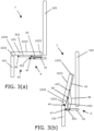
- FIG. 3(a) which shows the seat pan 103 in the sitting position
- Figure 3(b) which shows the seat pan 103 in a position between the sitting position and standing position.
- the seat pan 103 is configured to pivot about an axis at a pivot point 49 near the front edge 1031 of the seat pan 103, as opposed to a conventional cinema seat-style flip-up seat arrangement that would be configured to pivot from the rear edge 1032 of the seat pan 103, where the seat pan 103 meets the back rest 105.
- the seat pan 103 rotates, anticlockwise as shown in Figures 3(a) and 3(b) , so that the seating surface 1033 of the seat pan 103 moves upwardly and away from the back rest 105 while the underside 1034 of the seat pan (which faces the floor of the aircraft cabin 3 when the seat pan 103 is in the sitting position) moves to face the back rest 105.
- the underside 1034 of the seat pan 103 therefore faces the back rest 105, as can be seen in Figure 2 .
- the seat pan 103 is configured to move between the deployed position and the stowed position via the linkage arrangement 4 shown in Figure 3(a) and 3(b) .
- the linkage arrangement 4 comprises a substructure linkage rod 41 that is fixed upon the aircraft seat 1 substructure (not shown) connected to a seat pan linkage rod 43 that is fixed upon the underside 1034 of the seat pan 103 via an L-shaped pivoting rod 45.
- the pivoting rod 45 comprises a first arm 451 and a second arm 452 oriented at approximately 90 degrees to one another which together form the L-shape.
- the distal end of the first arm 451 is pivotally mounted to the substructure linkage rod 41 and the distal end of the second arm 452 is connected to the seat pan linkage rod 42.
- the seat pan 103 is therefore moveable with respect to the back rest 105 by pivotal movement of the seat pan 103 about a first axis at a first pivot point 47, where the pivoting rod 45 is connected to the substructure linkage rod 41, and by pivotal movement about a second axis at a second pivot point 49, where the pivoting rod 45 is connected to the seat pan linkage rod 43.
- the linkage arrangement 4 further comprises a spring 48 connected between the substructure linkage rod 41 and seat pan linkage rod 43 that biases the seat pan 103 towards the stowed position.
- An actuator arrangement (not shown) is configured to move the seat pan 103 from the stowed position to the deployed position against the resilient bias of the spring 48.
- the resilient bias of the spring 48 pushes the seat pan linkage rod 43 away from the substructure linkage rod 41.
- the seat pan 103 pivots through an angle of approximately 180 degrees about the second pivot point 49 in a first direction (anticlockwise as shown in Figures 3(a) and 3(b) ) while the pivoting rod 45 pivots through an angle of approximately 90 degrees about the first pivot point 47 in a second, opposite direction (clockwise as shown in Figures 3(a) and 3(b) ).
- This movement pushes the seating surface 1033 of the seat pan 103 upwardly and away from the back rest 105 into a position in which the seat pan 103 is oriented substantially parallel with the back rest, with the underside 1034 of the seat pan 103 facing the back rest 105, while also translating the seat pan 103 and leg rest 101 towards the back rest 105.
- the first arm 451 of the pivoting rod 45 sits parallel with and alongside the substructure linkage rod 41 and projects away from the back rest 105, while the second arm 452 of the pivoting rod 45 projects vertically upwards, perpendicular to the substructure linkage rod 41, with the seat pan linkage rod 43, which rotates by approximately 180 degrees with respect to the pivoting rod 45 when moving from the deployed position to the stowed position, projecting vertically upwards from the distal end of the second arm 452 of the pivoting rod 45.
- the sit-stand seat 1 were instead to use, for example, a cinema seat-style flip-up arrangement wherein the seat pan 103 was configured to pivot at the rear 1032 of the seat pan 103, the leg rest 101 would move upwardly and away from the back rest 105 before moving back towards the back rest 105 as the seat pan 103 flipped-upwards to a stowed position.
- This type of flip-up arrangement would therefore require more space for moving the seat 1 between a deployed and stowed configuration and would therefore be particularly inconvenient for a passenger who already has limited space to move within a seat unit 2.
- a cinema seat-style flip-up arrangement would also require some sort of mechanism to move the leg rest 101 to ensure that standing space is maximised. Therefore the presently disclosed sit-stand mechanism 4 is potentially much simpler than that would be needed for a flip-up-type seat.
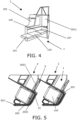
- the back rest 105 of the seat is moveable between the deployed, upright seating position, as shown in Figure 1 and a reclined, bed mode position as shown in Figure 4 in which the back rest 105 has been moved to a horizontal position in which it is substantially parallel with the deployed position of the seat pan 103 so that the passenger occupying the seat unit 2 can lie flat upon the seat 1.
- the seat 1 must be able to move between the different configurations of the seat 1 within the relatively confined space of the seat unit 2, a plan view of which is shown in Figure 5 , the seat unit 2 space being bound to the rear of the seat 1 by a seat unit shell 201 and being bound to the front by the seat unit shell 201' of the seat unit 2' in front.
- the seat pan 103 is configured to move forward, away from the rear wall 2011 of the seat unit 2 formed by the shell 201, as the back rest 105 reclines to create space for the horizontal oriented back rest 105 between the seat pan 103 and rear wall 2011.
- the leg rest 101 which is mounted at the front edge 1031 of the seat pan 103, rotates, clockwise as shown in figures 1 and 4 , to a position in which the leg rest 101 is also substantially parallel with the deployed position of the seat pan 103.
- the leg rest 101, seat pan 103, back rest 105, and head rest 107 (which does not rotate relative to the back rest when the seat 1 moves between the sitting configuration and bed mode configuration) therefore form a contiguous horizontal surface in the bed mode configuration of the seat 1.
- the seat pan 103 is also rotatable with respect to the back rest at a pivot point located at the rear 1032 of the seat pan 103 so that a passenger sitting in the seat can tilt the seat pan 103 to move their knees upwards or downwards to a desired seating position. Because the leg rest 101, seat pan 103, and back rest 105 are all independently moveable with respect to one another, as well as an upright sitting mode and a bed mode, the seat 1 can be configured in a multiplicity of other modes.
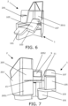
- the passenger can configure the seat to a "zero-gravity" seating position, as shown in Figure 6 , in which the back rest 105 is reclined, the seat pan 103 is tilted upwards so that the passenger's knees are positioned above their waist, and the leg rest 101 is rotated to a position in which it supports the passenger's lower legs.
- a "zero-gravity" seating position as shown in Figure 6 , in which the back rest 105 is reclined, the seat pan 103 is tilted upwards so that the passenger's knees are positioned above their waist, and the leg rest 101 is rotated to a position in which it supports the passenger's lower legs.
- the seat unit 2 further comprises display screen 9 for use by the passenger of the seat unit 2.
- the display screen 9 is rotatably mounted upon a forward wall 205 of the seat unit 2 (the forward wall 205 of the seat unit 2 being formed by the shell 201' of the seat unit 2' in front) via a telescopic arm 13 such that the display screen 9 can be rotated, moved from side-to-side and up and down with respect to the seat 1, as well as being able to be moved towards or away from the seat 1 via the telescopic action of the arm 13.
- Configured as such the display screen 9 is movable to any position of the seat 1 in which the user wishes to use the display screen 9.
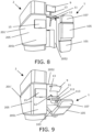
- the user is able to use the display screen in its stowed position to view the display screen 9 from the seat 1 when in an upright seating position; in Figure 8 the display screen 9 has been moved upwardly so that the display screen 9 can be used by a passenger whilst standing; and in Figure 9 the display screen 9 has been moved and tilted towards the seat 1 so the display screen 9 can be used by a passenger in the zero-gravity seating position.
- the primary table 11 comprises an integrated keyboard 111 and track pad 113 that are configured for use with the display screen 9.
- the display screen 9, keyboard 111 and track pad 113 are configured to connect to either of a personal electronic device belonging to the passenger, such as a tablet or laptop, or to an onboard computer using a wireless or wired connection.
- the primary table 11 is rotatably mounted via a telescopic arm 12 in substantially the same way as the table such that the table 11, and therefore track pad 111 and keyboard 113, are usable in the various positions of the chair, as shown in Figure 7 , Figure 8, and Figure 9 .
- the primary table 11 comprises a table cover (not shown) that can be used to cover the keyboard 111 and track pad 113 should the passenger not need access to the keyboard 111 or track pad 113, or should the passenger want to use the primary table 11 as an eating or working surface.
- the forward wall 205 of the seating unit is substantially S-shaped and comprises a projecting portion 2051 positioned to a side of the seat 1 that projects in the general direction of the seat 1 and a recessed portion 2052 that is positioned directly in front of the seat 1 so that the leg rest 101 and part of the seat pan 103 is received in the recessed portion 2052 of the forward wall 205 when the seat 1 is in a reclined or bed mode configuration
- a secondary, supplemental table 15 is mounted on the projecting portion 2051 of the forward wall 205 to provide the passenger of the seat unit 2 with extra surface space upon which to, for example, work or dine.
- the secondary table 15 is a hinge-mounted a flip-down table. In the deployed position of the secondary table 15, the primary table 11 can be pulled alongside the secondary table 15, as shown in Figure 7 and Figure 10 , to create an enlarged contiguous surface for use by the passenger of the seat unit 2.
- the seat unit 2 is particularly suited to a 1-2-1 cabin arrangement in which a plurality of rows of seat units 2 are arranged along a longitudinal axis X of an aircraft cabin 3, as shown in Figure 10 .
- a first row of seat units 5 extends between two sides of the cabin 31, 32 and comprises the seat unit 2 and a second seat unit 22 separated by a first aisle 8, and a third seat unit 23 and a fourth seat unit 24 separated by a second aisle 9 wherein the second seat unit 22 and third seat unit 23 are adjacent in the centre of the aircraft cabin 3.
- Each of the seat units are oriented such that each seat is oriented at an angle to the longitudinal axis X.
- a lowerable privacy screen 6 is positioned between the second seat unit 22 and third seat unit 23 that can be raised to act as a barrier between the seat units 22, 23 or lowered should the passengers sat in those seat units 22, 23 be travelling together and not wish to be separated.
Landscapes
- Engineering & Computer Science (AREA)
- Aviation & Aerospace Engineering (AREA)
- Transportation (AREA)
- Mechanical Engineering (AREA)
- Seats For Vehicles (AREA)
- Chairs For Special Purposes, Such As Reclining Chairs (AREA)
Description
- The present invention concerns an aircraft seat as disclosed in appended
claim 1. More particularly, but not exclusively, this invention concerns a sit-stand aircraft seat, a seat unit comprising an adjustable screen, and a seat unit comprising an adjustable table. The present invention also concerns an aircraft cabin comprising such seats and seat units. - The main activities undertaken by a business class traveller during flight are working and sleeping. Prior art aircraft passenger seats typically provide such a traveller with an upright seating mode that can be used to work from and a bed mode in which the aircraft seat reclines to a horizontal, or near-horizontal position for sleeping.
- An aircraft seating arrangement having greater flexibility is desirable as the traveller may wish to work in a range of positions, as is usually possible within the modern office environment, especially during long haul flights where extended periods of time are spent on board. Furthermore, the most comfortable seating position may be dependent on a particular passenger's size and stature, as well as personal preference, which means that an aircraft seating arrangement providing a variety of configuration options is more desirable to the passenger than a "one size fits all" arrangement.
-
EP1645507A1 discloses an aircraft seat comprising a seat pan which is movable to create standing space for a passenger. Specifically, the document discloses a support module with a first and a second support part, the first one being movable upwards and downwards, the second one being pivotally mounted to the first support part around a horizontal axis.WO2005/095210A1 discloses an aircraft seat having a seat pan that is movable to a retracted state that creates more space between rows of adjacent seats for e.g. passage, standing or exercise. -
US2017129611A1 discloses a passenger seating arrangement including pairings of first and second laterally-adjacent seats, wherein the first and second seats are positioned at different angles relative to a longitudinal aircraft axis and the first and second seats recline to different vertical elevations such that a bed surface of the first seat in a lay flat configuration can overlap a portion of a bed surface of the second seat in a lay flat configuration to maximize seating density. - The present invention seeks to mitigate the above-mentioned problems.
- The present invention provides, according to a first aspect, an aircraft passenger seat comprising a seat pan, a back rest and a leg rest according to
claim 1. - The back rest is moveable between an upright position and a reclined position in which the back rest is substantially parallel with a deployed position of the seat pan. The leg rest is moveable between a retracted position in which the leg rest is substantially perpendicular to the deployed position of the seat pan and an extended position in which it is positioned to support the legs of a passenger. The seat pan is moveable between a deployed position in which the seat pan occupies a first space and wherein a passenger can sit on the seat pan, and a stowed position in which the seat pan is moved out of the first space such that a passenger can stand in the first space. The back rest can be fixed in at least one intermediate position between the upright position and the reclined position. The seat pan is moveable between the deployed position and a tilted position in which seat pan is angled with respect to the back rest and the seat pan can be fixed in at least one intermediate position between the deployed position and tilted position.
- The term "upright" may correspond to a vertical position. However, it will also be understood by the skilled person to correspond to a position in which the back rest is oriented at an angle to the vertical. The term "vertical" here being with reference to a floor of an aircraft cabin to which the aircraft passenger seat is mounted in use. The seat may comprise a headrest.
- The present invention recognises that an aircraft passenger may not want to remain seated for the entire duration of a journey but that there is limited space within an aircraft for a passenger to stand. As such the present invention provides a sit-stand aircraft seat which is configurable between an upright sitting (seat pan deployed) position in which a passenger can sit upon seat pan with their back against the back rest, a reclined sitting (seat pan deployed) position in which the passenger can sit upon the seat pan with their back against the back rest in a reclined position, and a standing (seat pan stowed) position. In order to maximise limited aircraft cabin space, in the stowed position the seat pan has moved so that the passenger can stand in space that was occupied by the seat pan in the sitting (seat pan deployed) position.
- The aircraft passenger seat may be a business class aircraft passenger seat. The sit-stand function of the aircraft passenger seat is particularly advantageous for business class seating. A business class passenger may want to work for periods of time in a standing up position, as can be done in modern office environments, particularly during long-haul flights in which the time that is spent on board is significant.
- The back rest may be able to be fixed in a plurality or multiplicity of positions between the upright position and the reclined position. The reclined position may correspond to a bed configuration. The main in-flight activities of a typical business class traveller are working and sleeping. Therefore it is it is particularly advantageous to provide a sit-stand seat that also has a bed configuration.
- The seat pan is moveable between the deployed position and the tilted position in which seat pan is angled with respect to the back rest. An angle may be defined between the seat pan and back rest and the seat pan may be tilted to increase or decrease the angle. The seat pan may be tiltable towards the back rest to decrease the angle. The seat pan may be tiltable away from the back rest to increase the angle. A tiltable seat pan provides the seat with extra versatility, allowing the passenger to change their sitting position during flight by changing the angle of the seat pan.
- The seat pan may be able to be fixed in a plurality or multiplicity of positions between the deployed position and tilted position.
- The leg rest may be positioned substantially parallel with the seat pan in the extended position. The leg rest may be able to be fixed in at least one intermediate position between the retracted position and the extended position. The leg rest may be rotatably mounted to the seat pan and moveable between the retracted position and the extended position by rotation of the leg rest with respect to the seat pan. The seat pan may comprise a front edge and a rear, opposite edge. The seat pan may meet the back rest at the rear edge and the leg rest may be mounted upon the seat pan at or near the front edge.
- The back rest may be able to be fixed in a plurality of positions between the upright position and the reclined position. The leg rest may be able to be fixed in a plurality of positions between the retracted position and the extended position. This arrangement is particularly advantageous because the passenger is provided with a large variety of combinations of the relative positions of the seat pan, back rest, and leg rest. For example, the passenger may choose to sit in the so-called "zero gravity" sitting position in which the passenger is supported in a position between sitting down and lying flat in which the passenger's back is reclined and their knees positioned above their waist. This position provides a feeling of weightlessness and supports the body in an ergonomic way. The most comfortable zero-gravity seating position is largely dependent on the size and stature of the passenger as well as personal preference. As such, it is particularly beneficial to have a large number of configurations of the seat.
- When the seat pan is in the deployed position, a rear edge of the seat pan may be adjacent the back rest. The seat pan may be configured to move from the deployed position to the stowed position by rotating the seat pan such that the rear edge of the seat pan rotates away from the back rest. The rear edge of the seat pan may move upwardly in relation to back rest when moving from the deployed position to the stowed position. The seat pan may comprise a seating surface on a first side of the seat pan. The seat pan may comprise an underside on a second, opposite side of the seat pan. The underside of the seat pan may, in use, face the floor of the aircraft cabin when the seat pan is in the deployed position. The underside of the seat pan may rotate towards the back rest when the seat pan moves between the deployed position and the stowed position. The underside of the seat pan may face the back rest when the seat pan is in the stowed position.
- The seat pan may be configured to rotate about an axis to move the seat pan from the deployed position to the stowed position, wherein the axis is positioned towards or at a front edge of the seat pan, the front edge of the seat pan being located on the opposite side of the seat pan to the rear edge of the seat pan. The axis may be positioned closer to the front edge of the seat pan than to the rear edge of the seat pan.
- The leg rest may be mounted to the seat pan, in a region of the front edge of the seat pan. The leg rest may be mounted to the front edge of the seat pan. The leg rest may move towards the back rest as the seat pan moves from the deployed position to the stowed position. The leg rest may not rotate as the seat pan moves from the deployed position to the stowed position. The leg rest may move substantially only in one plane as the seat pan moves from the deployed position to the stowed position. The leg rest may move substantially horizontally, but not vertically, as the seat pan moves from the deployed position to the stowed position.
- As mentioned above, the seat pan may be configured to move from the deployed position to the stowed position by rotating the seat pan such that a rear edge of the seat pan rotates away from the back rest. This particular way in which the seat pan can be configured to rotate is particularly advantageous where the aircraft seat comprises a leg rest because as the seat pan rotates from the deployed position to the stowed position, the leg rest rotates with the seat pan towards the back rest. If the sit-stand seat were instead to use, for example, a cinema seat-style flip-up arrangement wherein the seat pan was configured to rotate about an axis at the rear edge of the seat pan, the leg rest would move upwardly and away from the back rest before moving back towards the back rest as the seat pan rotates towards the stowed position. As such, a passenger stood in front of the seat as it rotates to the stowed position would have to move out of the way of the leg rest, such an arrangement is particularly inconvenient given the limited space that is typically available within an aircraft cabin. Furthermore, a cinema seat-style flip-up arrangement would also require some sort of mechanism to move the leg rest to ensure that standing space is maximised. Therefore the presently disclosed sit-stand mechanism is potentially much simpler than that would be needed for a flip-up-type seat.
- The leg rest may be substantially aligned with the seat pan and positioned below the seat pan when the seat pan is in the stowed position. The seat pan may be positioned substantially parallel with the leg rest when the seat pan is in the stowed position. The seat pan may be substantially parallel with the back rest when the seat pan is in the stowed position.
- According to a second aspect, the present invention provides an aircraft passenger seat unit comprising an aircraft passenger seat according to the first aspect of the invention. The aircraft passenger seat unit comprises a table that is moveable between: a lowered position in which a passenger can use the table while sitting upon the seat pan, and a raised position in which the passenger can use the table while standing in the first space. The table may be moveable from side-to-side with respect to the seat. The table may be moveable towards or away from the seat. The table may be tiltable with respect to the seat. The table may comprise hinges so that at least a portion of the table is tiltable via hinges.
- As mentioned, a business class passenger may want to work for periods of time in a standing up position, as can be done in modern office environments, particularly during long-haul flights in which the time that is spent on board is significant. The present invention therefore provides a sit-stand desk as which the passenger can work whilst sitting or standing.
- The table may comprise an integrated display screen control device, such as a keyboard or trackpad. The display screen control device may be configurable to connect to a personal electronic device such as a tablet or laptop using a wireless or wired connection. The display screen control device may be configurable to connect to an onboard computer using a wireless or wired connection. The table may comprise both a keyboard and a trackpad.
- The aircraft passenger seat unit may comprise a display screen. The seat unit may further comprise a telescopic arm mounted at one end to a structure of the seat unit wherein the display screen is rotatably mounted to an opposite end of the telescopic arm, such that the display screen can be moved from side-to-side and up and down with respect to the seat, as well as being rotatable and being able to be moved towards or away from the seat via the telescopic action of the arm. Configured as such, the display screen is usable in a variety of positions within the seat unit. As such, a passenger may view the display screen, for example, whilst in a seated, standing, or reclined position.
- The screen may be configurable to connect to a personal electronic device such as a tablet or laptop using a wireless or wired connection. The screen may be configurable to connect to an onboard computer using a wireless or wired connection.
- The aircraft passenger seat unit may further comprise a stowable table, wherein the table comprises an integrated display screen control device, such as a keyboard or trackpad. The table may be a first table. The display screen control device may be configurable to connect to a personal electronic device such as a tablet or laptop using a wireless or wired connection. The display screen control device may be configurable to connect to an onboard computer using a wireless or wired connection. The table may comprise both a keyboard and a trackpad.
- The table may comprise a first surface and a second surface wherein the first surface provides the integrated display screen control device. The table may have a first configuration in which a passenger is able to use the first surface but not the second surface and a second configuration in which the passenger is able to use the second surface but not the first surface. The first surface and the second surface may be substantially the same size. In the second configuration, the second surface may be in a position in which it covers over the first surface. The table may provide the first surface on a first side of the table and the second surface on a second, opposite side of the table, wherein the table is configured to be rotatable so that the user can access the first surface or second surface by rotating the table.
- The aircraft seat unit may further comprise a supplementary table, wherein the table is moveable to a position alongside the supplementary table to create an enlarged table surface formed by the table and the supplementary table.
- The seat may comprise a seat pan moveable between: a deployed position in which the seat pan occupies a first space and wherein a passenger can sit on the seat pan, and a stowed position in which the seat pan is moved out of the first space such that a passenger can stand in the first space.
- According to a third aspect, the present invention provides an aircraft cabin comprising a plurality of seat units according to the second aspect of the invention. Each seat unit may be adjacent an aisle. The aircraft cabin may have a row extending between two sides of the cabin, the row comprising exactly four seat units, wherein the row of seat units comprises a first seat unit and a second seat unit separated by a first aisle, and a third seat unit and a fourth seat unit separated by a second aisle. The second seat unit and third seat unit may be adjacent and located in the centre of the aircraft cabin.
- The seat units according to the embodiments of the invention are particularly suited to a 1-2-1 cabin arrangement in which a plurality of rows of seat units are arranged along a longitudinal axis of an aircraft cabin. A privacy screen may be positioned between the second and third seat units. The privacy screen may be moveable between a stowed position and a deployed position, wherein in the deployed position the privacy screen acts as a barrier between the second and third seat units. The aircraft cabin may comprise a longitudinal axis and each seat may be oriented at an angle to the longitudinal axis.
- It will of course be appreciated that features described in relation to one aspect of the present invention may be incorporated into other aspects of the present invention, when falling within the scope of the appended claims.
- Embodiments of the present invention will now be described by way of example only with reference to the accompanying schematic drawings of which:
-
Figure 1 shows a seat unit comprising an aircraft passenger seat according to an embodiment of the invention wherein the aircraft passenger seat is configured in a deployed, upright seating position; -
Figure 2 shows the seat unit ofFigure 1 with the aircraft passenger seat in a stowed, standing position; -
Figure 3(a) is a schematic view of the aircraft passenger seat and seat folding mechanism with the aircraft passenger seat in the deployed position; -
Figure 3(b) is a schematic view of the aircraft passenger seat and seat folding mechanism with the aircraft passenger seat located between the stowed and the deployed positions; -
Figure 4 shows the seat unit ofFigure 1 with the aircraft passenger seat in bed mode position; -
Figure 5 plan view showing the seat unit ofFigure 1 with a neighbouring seat unit located in front; -
Figure 6 shows the seat unit ofFigure 1 with the aircraft passenger seat in a zero-gravity seating position; -
Figure 7 is a rear view of the seat unit as shown inFigure 1 , with the seat unit shell not shown, and with the forward wall of the seat unit shown; -
Figure 8 is a rear view of the seat unit as shown inFigure 2 , with the seat unit shell not shown, and with the forward wall of the seat unit shown; -
Figure 9 is a rear view of the seat unit as shown inFigure 6 , with the seat unit shell not shown, and with the forward wall of the seat unit shown; and -
Figure 10 is a plan view of an aircraft cabin comprising the seat unit ofFigure 1 . - An
aircraft passenger seat 1 according to an embodiment of the invention is shown situated within aseat unit 2 inFigure 1 . Theaircraft passenger seat 1 comprises aleg rest 101, aseat pan 103, aback rest 105, and aheadrest 107. Theaircraft passenger seat 1 is a sit-stand seat that is moveable between a deployed position in which theseat 1 is configured so that a passenger can sit upon theseat pan 103, as shown inFigure 1 , and a stowed position, as shown inFigure 2 , in which theseat pan 103 andleg rest 101 have been moved from the sitting position so that the passenger occupying theseat unit 2 can stand in a space that is occupied by theseat pan 103 andleg rest 101 when the seat is in the sitting configuration. - The mechanism that enables the sit-stand conversion of the seat is shown in more detail in
Figure 3(a) , which shows theseat pan 103 in the sitting position, andFigure 3(b) , which shows theseat pan 103 in a position between the sitting position and standing position. As can be seen fromFigure 3(b) , theseat pan 103 is configured to pivot about an axis at apivot point 49 near thefront edge 1031 of theseat pan 103, as opposed to a conventional cinema seat-style flip-up seat arrangement that would be configured to pivot from therear edge 1032 of theseat pan 103, where theseat pan 103 meets theback rest 105. - To move from the deployed position to the stowed position, the
seat pan 103 rotates, anticlockwise as shown inFigures 3(a) and 3(b) , so that theseating surface 1033 of theseat pan 103 moves upwardly and away from theback rest 105 while theunderside 1034 of the seat pan (which faces the floor of theaircraft cabin 3 when theseat pan 103 is in the sitting position) moves to face theback rest 105. In the stowed position, theunderside 1034 of theseat pan 103 therefore faces theback rest 105, as can be seen inFigure 2 . - The
seat pan 103 is configured to move between the deployed position and the stowed position via thelinkage arrangement 4 shown inFigure 3(a) and 3(b) . Thelinkage arrangement 4 comprises asubstructure linkage rod 41 that is fixed upon theaircraft seat 1 substructure (not shown) connected to a seatpan linkage rod 43 that is fixed upon theunderside 1034 of theseat pan 103 via an L-shapedpivoting rod 45. The pivotingrod 45 comprises afirst arm 451 and asecond arm 452 oriented at approximately 90 degrees to one another which together form the L-shape. The distal end of thefirst arm 451 is pivotally mounted to thesubstructure linkage rod 41 and the distal end of thesecond arm 452 is connected to the seat pan linkage rod 42. Theseat pan 103 is therefore moveable with respect to theback rest 105 by pivotal movement of theseat pan 103 about a first axis at afirst pivot point 47, where the pivotingrod 45 is connected to thesubstructure linkage rod 41, and by pivotal movement about a second axis at asecond pivot point 49, where the pivotingrod 45 is connected to the seatpan linkage rod 43. Such an arrangement enables theseat pan 103 to rotate and move towards theback rest 105 when moving from the deployed position to the stowed position, as will be described in more detail below. Thelinkage arrangement 4 further comprises aspring 48 connected between thesubstructure linkage rod 41 and seatpan linkage rod 43 that biases theseat pan 103 towards the stowed position. An actuator arrangement (not shown) is configured to move theseat pan 103 from the stowed position to the deployed position against the resilient bias of thespring 48. - In the deployed position of the
seat pan 103, shown inFigure 3(a) , the pivotingrod 45 has been rotated to a position in which thesecond arm 452 projects away from theback rest 105 and sits alongside the seatpan linkage rod 43, against theunderside 1034 of theseat pan 103. In this position thefirst arm 451 projects downwardly to thesubstructure linkage rod 41 which, in the deployed position of theseat pan 103, is oriented parallel to the seatpan linkage rod 43 andsecond arm 452 of the pivotingrod 45. - To move the
seat pan 103 from the deployed position to the stowed position, the resilient bias of thespring 48 pushes the seatpan linkage rod 43 away from thesubstructure linkage rod 41. As this happens, theseat pan 103 pivots through an angle of approximately 180 degrees about thesecond pivot point 49 in a first direction (anticlockwise as shown inFigures 3(a) and 3(b) ) while the pivotingrod 45 pivots through an angle of approximately 90 degrees about thefirst pivot point 47 in a second, opposite direction (clockwise as shown inFigures 3(a) and 3(b) ). This movement pushes theseating surface 1033 of theseat pan 103 upwardly and away from theback rest 105 into a position in which theseat pan 103 is oriented substantially parallel with the back rest, with theunderside 1034 of theseat pan 103 facing theback rest 105, while also translating theseat pan 103 andleg rest 101 towards theback rest 105. - In the stowed position of the
seat pan 103, thefirst arm 451 of the pivotingrod 45 sits parallel with and alongside thesubstructure linkage rod 41 and projects away from theback rest 105, while thesecond arm 452 of the pivotingrod 45 projects vertically upwards, perpendicular to thesubstructure linkage rod 41, with the seatpan linkage rod 43, which rotates by approximately 180 degrees with respect to the pivotingrod 45 when moving from the deployed position to the stowed position, projecting vertically upwards from the distal end of thesecond arm 452 of the pivotingrod 45. - As can be seen in
Figure 2 , in the stowed position theseat pan 103 has moved out of the space that theseat pan 103 occupies when in the deployed position such that a passenger occupying theseat unit 2 can stand in the space that was occupied by theseat pan 103 when theseat pan 103 was in the deployed position. As can be seen fromFigures 3(a) and 3(b) , a benefit of this particular seat folding mechanism is that theleg rest 101 simply moves horizontally towards theback rest 105 as theseat pan 103 moves from the deployed position to the stowed position. If the sit-stand seat 1 were instead to use, for example, a cinema seat-style flip-up arrangement wherein theseat pan 103 was configured to pivot at the rear 1032 of theseat pan 103, theleg rest 101 would move upwardly and away from theback rest 105 before moving back towards theback rest 105 as theseat pan 103 flipped-upwards to a stowed position. This type of flip-up arrangement would therefore require more space for moving theseat 1 between a deployed and stowed configuration and would therefore be particularly inconvenient for a passenger who already has limited space to move within aseat unit 2. Furthermore, a cinema seat-style flip-up arrangement would also require some sort of mechanism to move theleg rest 101 to ensure that standing space is maximised. Therefore the presently disclosed sit-stand mechanism 4 is potentially much simpler than that would be needed for a flip-up-type seat. - In addition to the
aircraft seat 1 comprising a sit-stand function, theback rest 105 of the seat is moveable between the deployed, upright seating position, as shown inFigure 1 and a reclined, bed mode position as shown inFigure 4 in which theback rest 105 has been moved to a horizontal position in which it is substantially parallel with the deployed position of theseat pan 103 so that the passenger occupying theseat unit 2 can lie flat upon theseat 1. Theseat 1 must be able to move between the different configurations of theseat 1 within the relatively confined space of theseat unit 2, a plan view of which is shown inFigure 5 , theseat unit 2 space being bound to the rear of theseat 1 by aseat unit shell 201 and being bound to the front by the seat unit shell 201' of the seat unit 2' in front. To achieve the bed mode position therefore, theseat pan 103 is configured to move forward, away from therear wall 2011 of theseat unit 2 formed by theshell 201, as theback rest 105 reclines to create space for the horizontal oriented backrest 105 between theseat pan 103 andrear wall 2011. As this happens, theleg rest 101, which is mounted at thefront edge 1031 of theseat pan 103, rotates, clockwise as shown infigures 1 and4 , to a position in which theleg rest 101 is also substantially parallel with the deployed position of theseat pan 103. Theleg rest 101,seat pan 103, backrest 105, and head rest 107 (which does not rotate relative to the back rest when theseat 1 moves between the sitting configuration and bed mode configuration) therefore form a contiguous horizontal surface in the bed mode configuration of theseat 1. - The
seat pan 103 is also rotatable with respect to the back rest at a pivot point located at the rear 1032 of theseat pan 103 so that a passenger sitting in the seat can tilt theseat pan 103 to move their knees upwards or downwards to a desired seating position. Because theleg rest 101,seat pan 103, and back rest 105 are all independently moveable with respect to one another, as well as an upright sitting mode and a bed mode, theseat 1 can be configured in a multiplicity of other modes. For example, the passenger can configure the seat to a "zero-gravity" seating position, as shown inFigure 6 , in which theback rest 105 is reclined, theseat pan 103 is tilted upwards so that the passenger's knees are positioned above their waist, and theleg rest 101 is rotated to a position in which it supports the passenger's lower legs. - The
seat unit 2 further comprisesdisplay screen 9 for use by the passenger of theseat unit 2. Thedisplay screen 9 is rotatably mounted upon aforward wall 205 of the seat unit 2 (theforward wall 205 of theseat unit 2 being formed by the shell 201' of the seat unit 2' in front) via atelescopic arm 13 such that thedisplay screen 9 can be rotated, moved from side-to-side and up and down with respect to theseat 1, as well as being able to be moved towards or away from theseat 1 via the telescopic action of thearm 13. Configured as such thedisplay screen 9 is movable to any position of theseat 1 in which the user wishes to use thedisplay screen 9. For example, inFigure 7 the user is able to use the display screen in its stowed position to view thedisplay screen 9 from theseat 1 when in an upright seating position; inFigure 8 thedisplay screen 9 has been moved upwardly so that thedisplay screen 9 can be used by a passenger whilst standing; and inFigure 9 thedisplay screen 9 has been moved and tilted towards theseat 1 so thedisplay screen 9 can be used by a passenger in the zero-gravity seating position. - Mounted to the
forward wall 205 of the seat unit, below the display screen is a primary table 11. The primary table 11 comprises anintegrated keyboard 111 andtrack pad 113 that are configured for use with thedisplay screen 9. Thedisplay screen 9,keyboard 111 andtrack pad 113 are configured to connect to either of a personal electronic device belonging to the passenger, such as a tablet or laptop, or to an onboard computer using a wireless or wired connection. The primary table 11 is rotatably mounted via atelescopic arm 12 in substantially the same way as the table such that the table 11, and thereforetrack pad 111 andkeyboard 113, are usable in the various positions of the chair, as shown inFigure 7 ,Figure 8, and Figure 9 . The primary table 11 comprises a table cover (not shown) that can be used to cover thekeyboard 111 andtrack pad 113 should the passenger not need access to thekeyboard 111 ortrack pad 113, or should the passenger want to use the primary table 11 as an eating or working surface. - As can be seen in
Figure 5 , theforward wall 205 of the seating unit is substantially S-shaped and comprises a projectingportion 2051 positioned to a side of theseat 1 that projects in the general direction of theseat 1 and a recessedportion 2052 that is positioned directly in front of theseat 1 so that theleg rest 101 and part of theseat pan 103 is received in the recessedportion 2052 of theforward wall 205 when theseat 1 is in a reclined or bed mode configuration As can be seen inFigures 7 ,8 ,9 , and10 , a secondary, supplemental table 15 is mounted on the projectingportion 2051 of theforward wall 205 to provide the passenger of theseat unit 2 with extra surface space upon which to, for example, work or dine. The secondary table 15 is a hinge-mounted a flip-down table. In the deployed position of the secondary table 15, the primary table 11 can be pulled alongside the secondary table 15, as shown inFigure 7 andFigure 10 , to create an enlarged contiguous surface for use by the passenger of theseat unit 2. - The
seat unit 2 is particularly suited to a 1-2-1 cabin arrangement in which a plurality of rows ofseat units 2 are arranged along a longitudinal axis X of anaircraft cabin 3, as shown inFigure 10 . As can be seen, a first row ofseat units 5 extends between two sides of thecabin seat unit 2 and asecond seat unit 22 separated by afirst aisle 8, and athird seat unit 23 and afourth seat unit 24 separated by asecond aisle 9 wherein thesecond seat unit 22 andthird seat unit 23 are adjacent in the centre of theaircraft cabin 3. Each of the seat units are oriented such that each seat is oriented at an angle to the longitudinal axis X. Alowerable privacy screen 6 is positioned between thesecond seat unit 22 andthird seat unit 23 that can be raised to act as a barrier between theseat units seat units - It will be appreciated by the reader that integers or features of the invention that are described as preferable, advantageous, convenient or the like are optional and do not limit the scope of the independent claims. Moreover, it is to be understood that such optional integers or features, whilst of possible benefit in some embodiments of the invention, may not be desirable, and may therefore be absent, in other embodiments.
Claims (14)
- An aircraft passenger seat (1) comprising a seat pan (103) and a back rest (105),
wherein the seat pan (103) is moveable between:a deployed position in which the seat pan occupies a first space and wherein a passenger can sit on the seat pan (103), anda stowed position in which the seat pan (103) is moved out of the first space such that a passenger can stand in the first space;whereinthe seat pan (103) is moveable between the deployed position and a tilted position in which the seat pan (103) is angled with respect to the back rest (105) and the seat pan (103) can be fixed in at least one intermediate position between the deployed position and tilted position;the back rest (105) is moveable between an upright position and a reclined position in which the back rest (105) is substantially parallel with a deployed position of the seat pan (103) and the back rest (105) can be fixed in at least one intermediate position between the upright position and the reclined position; andthe aircraft passenger seat (1) further comprises a leg rest (101) that is moveable between a retracted position in which the leg rest (101) is substantially perpendicular to the deployed position of the seat pan (103) and an extended position in which it is positioned to support the legs of a passenger. - An aircraft passenger seat (1) according to claim 1, wherein the leg rest (101) can be fixed in at least one intermediate position between the retracted position and the extended position.
- An aircraft passenger seat (1) according to claim 1 or claim 2, wherein the leg rest (101) is rotatably mounted to the seat pan (103) and moveable between the retracted position and the extended position by rotation of the leg rest (101) with respect to the seat pan (103).
- An aircraft passenger seat (1) according to any preceding claim, wherein:the seat pan (103) can be fixed in a plurality of positions between the deployed position and the tilted position,the back rest (105) can be fixed in a plurality of positions between the upright position and the reclined position, andthe leg rest (101) can be fixed in a plurality of positions between the retracted position and the extended position.
- A business class aircraft passenger seat (1) comprising an aircraft passenger seat according to any preceding claim, wherein the seat pan (103) comprises a seating surface on a first side of the seat pan (103) and an underside on a second, opposite side of the seat pan (103), and wherein the aircraft seat is configured such that:in the deployed position a rear edge of the seat pan (103) is adjacent the back rest (105), andin the stowed position the underside of the seat pan (103) faces the back rest (105), andwherein the seat pan (103) is configured to move from the deployed position to the stowed position by rotating the seat pan (103) such that the rear edge rotates away from the back rest (105).
- A business class aircraft passenger seat (1) according to claim 5, wherein the seat pan (103) is configured to rotate about an axis to move the seat pan (103) from the deployed position to the stowed position, wherein the axis is positioned towards or at a front edge of the seat pan (103), the front edge of the seat pan (103) being located on the opposite side of the seat pan (103) to the rear edge of the seat pan (103).
- A business class aircraft passenger seat (1) according to claim 5 or claim 6, wherein the leg rest (101) is mounted to the seat pan (103), in a region of the front edge of the seat pan (103) and configured such that the leg rest (101) is substantially aligned with the seat pan (103) and positioned below the seat pan (103) when the seat pan (103) is in the stowed position.
- An aircraft passenger seat unit (2) comprising an aircraft passenger seat (1) according to any of claims 1 to 4 or a business class aircraft passenger seat according to any of claims 5 to 7, wherein the aircraft passenger seat unit (2) further comprises a table (11), wherein the table (11) is moveable between:a lowered position in which a passenger can use the table (11) while sitting upon the seat pan (103), anda raised position in which the passenger can use the table (11) while standing in the first space.
- An aircraft passenger seat unit (2) according to claim 8, wherein the table (11) comprises an integrated display screen control device, such as a keyboard (111) or trackpad (113).
- An aircraft passenger seat unit (2) according to claim 9, wherein the table (11) comprises a first surface and a second surface and wherein the first surface provides the integrated display screen control device, the table having a first configuration in which a passenger is able to use the first surface but not the second surface and a second configuration in which the passenger is able to use the second surface but not the first surface.
- An aircraft passenger seat unit (2) according to claim 10 further comprising a supplementary table (15), wherein the table (11) is moveable to a position alongside the supplementary table (15) to create an enlarged table surface formed by the table (11) and the supplementary table (15).
- An aircraft passenger seat unit (2) according to any of claims 8 to 11 further comprising a display screen (9) and a telescopic arm (13), wherein the telescopic arm (13) is mounted at one end to a structure of the seat unit (2) and wherein the display screen (9) is rotatably mounted to an opposite end of the telescopic arm (13), such that the display screen (9) can be moved from side-to-side and up and down with respect to the seat, as well as being rotatable and being able to be moved towards or away from the seat via the telescopic action of the arm.
- An aircraft cabin comprising a plurality of aircraft passenger seat units (2), wherein the plurality of aircraft passenger seat units are aircraft passenger seat units (2) according to any of claims 8 to 12.
- An aircraft cabin according to claim 13 having a row (5) extending between two sides of the cabin, the row (5) comprising exactly four seat units (2, 22, 23, 24), wherein the row of seat units comprises a first seat unit (2) and a second seat unit (22) separated by a first aisle (8), and a third seat unit (23) and a fourth seat unit (24) separated by a second aisle (9).
Applications Claiming Priority (2)
| Application Number | Priority Date | Filing Date | Title |
|---|---|---|---|
| GB1817722.0A GB2580292B (en) | 2018-10-30 | 2018-10-30 | Aircraft seat and cabin arrangement |
| PCT/GB2019/053048 WO2020089600A1 (en) | 2018-10-30 | 2019-10-29 | Aircraft seat and cabin arrangement |
Publications (2)
| Publication Number | Publication Date |
|---|---|
| EP3873806A1 EP3873806A1 (en) | 2021-09-08 |
| EP3873806B1 true EP3873806B1 (en) | 2024-08-07 |
Family
ID=64655441
Family Applications (1)
| Application Number | Title | Priority Date | Filing Date |
|---|---|---|---|
| EP19797342.3A Active EP3873806B1 (en) | 2018-10-30 | 2019-10-29 | Aircraft seat and cabin arrangement |
Country Status (5)
| Country | Link |
|---|---|
| US (1) | US11518520B2 (en) |
| EP (1) | EP3873806B1 (en) |
| CN (1) | CN112930301B (en) |
| GB (1) | GB2580292B (en) |
| WO (1) | WO2020089600A1 (en) |
Families Citing this family (5)
| Publication number | Priority date | Publication date | Assignee | Title |
|---|---|---|---|---|
| USD1020327S1 (en) * | 2019-03-29 | 2024-04-02 | Safran Seats | Cabinet for seat |
| USD955121S1 (en) * | 2019-11-01 | 2022-06-21 | Napstar, Llc | Rest booth |
| KR102922370B1 (en) * | 2020-11-10 | 2026-02-04 | 현대자동차주식회사 | Seat of autonomous driving vehicle |
| US12128807B2 (en) * | 2022-03-21 | 2024-10-29 | Ford Global Technologies, Llc | Seat-mounted work surface |
| US12472849B2 (en) * | 2022-08-31 | 2025-11-18 | Lear Corporation | Seat assembly |
Family Cites Families (32)
| Publication number | Priority date | Publication date | Assignee | Title |
|---|---|---|---|---|
| US1732782A (en) * | 1925-04-22 | 1929-10-22 | Augustus F Wasmuth | Wall seat |
| FR622622A (en) * | 1926-10-07 | 1927-06-02 | Auxiliary balanced seat for motor cars | |
| GB2213368B (en) * | 1987-12-08 | 1991-09-04 | Land Rover Uk Ltd | Folding seat |
| DE3822574A1 (en) * | 1988-07-04 | 1990-01-11 | Messerschmitt Boelkow Blohm | SEAT, ESPECIALLY FOR A FLIGHT ATTENDANT |
| US5179447A (en) * | 1991-04-16 | 1993-01-12 | Hughes-Avicom International, Inc. | Personal video player and monitor assembly for airline passenger seat console |
| US20010000639A1 (en) * | 1997-02-20 | 2001-05-03 | Singapore Airlines Ltd. | Transport accommodation |
| JP3977515B2 (en) * | 1997-06-10 | 2007-09-19 | デルタ工業株式会社 | Sheet table structure |
| GB2369774A (en) * | 1998-06-06 | 2002-06-12 | Magna Seating Systems Ltd | folding mechanism for a vehicle seat head restraint |
| US6375259B1 (en) * | 2000-05-03 | 2002-04-23 | Hsi Kuang Ma | Foldaway panel display on a chair |
| FR2838085B1 (en) * | 2002-04-08 | 2004-07-16 | Sicma Aero Seat | SEAT WITH MECHANICAL SYNCHRONIZATION OF THE LEG BACK AND REST |
| GB0407126D0 (en) * | 2004-03-30 | 2004-05-05 | Thompson James | Reclining seat |
| EP1645507A1 (en) * | 2004-10-06 | 2006-04-12 | Nederlandse Organisatie voor toegepast-natuurwetenschappelijk onderzoek TNO | System for transportation and/or storage of persons in transportation vehicles |
| JP4176118B2 (en) | 2006-07-31 | 2008-11-05 | トヨタ自動車株式会社 | Vehicle seat device |
| US9308836B2 (en) * | 2006-10-26 | 2016-04-12 | Ford Global Technologies, Llc | Folding and reclining seat for vehicle |
| DE102007002371B3 (en) * | 2007-01-16 | 2008-05-21 | Autoflug Gmbh | Safety seat for e.g. land vehicle, has belt sections with shoulder belts guided up to fastener arranged at front edge of seat part, where shoulder belts are connected with one another by transverse joints |
| WO2010086822A1 (en) * | 2009-01-30 | 2010-08-05 | Air New Zealand Limited | A vehicle seat with reclining back and leg rest |
| CA2750767C (en) * | 2009-01-30 | 2018-04-10 | Air New Zealand Limited | Seating arrangement, seat unit, tray table and seating system |
| DE102011077773A1 (en) * | 2011-06-17 | 2012-12-20 | Voith Patent Gmbh | Stowable couch for installation in a passenger vehicle |
| EP2983563B1 (en) * | 2013-04-08 | 2019-09-25 | B/E Aerospace, Inc. | Vehicle seat with simultaneous articulation of seat pan and seat back |
| US9856024B2 (en) * | 2013-06-18 | 2018-01-02 | B/E Aerospace, Inc. | Compact aircraft cabin attendant seat |
| CN103350654B (en) * | 2013-07-31 | 2016-04-13 | 陈映青 | A kind of height-adjustable bearing device |
| CN203511384U (en) * | 2013-09-18 | 2014-04-02 | 江苏科新汽车装饰件有限公司 | Automobile sleeper lifting table structure |
| WO2015073363A1 (en) * | 2013-11-12 | 2015-05-21 | B/E Aerospace, Inc. | Aircraft seat with taxi, takeoff and landing lie flat position capability |
| US9446849B1 (en) * | 2015-03-27 | 2016-09-20 | Ami Industries, Inc. | Stowable reclining seat with lateral translation linkage |
| DE102015110369B3 (en) * | 2015-06-26 | 2016-11-24 | Peak Technology GmbH | Airplane seat with seat reclining function |
| US10875653B2 (en) * | 2015-09-22 | 2020-12-29 | Safran Seats | Aircraft cabin arrangement optimised for the installation of seats for the flight crew |
| EP3374264B1 (en) * | 2015-11-10 | 2022-01-05 | Safran Seats | Aircraft seat for crew personnel |
| US10532817B2 (en) * | 2015-11-11 | 2020-01-14 | B/E Aerospace, Inc. | Aircraft seating arrangement with enhanced lay flat position spacing |
| CN107097960A (en) * | 2017-04-01 | 2017-08-29 | 中国商用飞机有限责任公司北京民用飞机技术研究中心 | It is a kind of to reply seat certainly for aviation |
| GB2563051A (en) * | 2017-06-01 | 2018-12-05 | James Robinson Dominic | A Seat assembly |
| US10464679B2 (en) * | 2017-08-22 | 2019-11-05 | Ami Industries, Inc. | Stowable seat with pivoting seat pan for advanced comfort |
| CN109677619A (en) * | 2018-12-06 | 2019-04-26 | 芜湖市努尔航空信息科技有限公司 | A kind of aero seat dinner table board convenient for adjusting |
-
2018
- 2018-10-30 GB GB1817722.0A patent/GB2580292B/en active Active
-
2019
- 2019-10-29 US US17/289,916 patent/US11518520B2/en active Active
- 2019-10-29 WO PCT/GB2019/053048 patent/WO2020089600A1/en not_active Ceased
- 2019-10-29 EP EP19797342.3A patent/EP3873806B1/en active Active
- 2019-10-29 CN CN201980071155.5A patent/CN112930301B/en active Active
Also Published As
| Publication number | Publication date |
|---|---|
| GB2580292B (en) | 2022-11-30 |
| WO2020089600A1 (en) | 2020-05-07 |
| EP3873806A1 (en) | 2021-09-08 |
| GB201817722D0 (en) | 2018-12-19 |
| GB2580292A (en) | 2020-07-22 |
| US11518520B2 (en) | 2022-12-06 |
| US20220001992A1 (en) | 2022-01-06 |
| CN112930301B (en) | 2023-12-01 |
| CN112930301A (en) | 2021-06-08 |
Similar Documents
| Publication | Publication Date | Title |
|---|---|---|
| EP3873806B1 (en) | Aircraft seat and cabin arrangement | |
| JP5097208B2 (en) | Moving and rotatable passenger seat | |
| US6669141B2 (en) | Aircraft passenger cabin with rotatable passenger seats | |
| JP4690548B2 (en) | Seat unit | |
| JP6567545B2 (en) | Seat unit | |
| EP2720944B1 (en) | Flexible-usage travel suite | |
| US8342450B2 (en) | Seating arrangement of a vehicle compartment | |
| JP4719688B2 (en) | Frame structure for vehicle passenger seat | |
| CN110091995B (en) | Work-dining aircraft seat with tilt and shift articulation | |
| CN110506004B (en) | Passenger seat with comfortable layout | |
| CN113613949A (en) | Passenger seat unit for an aircraft cabin | |
| JP2007517547A (en) | Vehicle seat with adjustable headrest | |
| EP3810507B1 (en) | An aircraft seat unit | |
| US7490906B2 (en) | Seat backrest for the crew rest compartment of an aircraft | |
| US20250388324A1 (en) | Aircraft Seat | |
| US12486034B2 (en) | Reclining seat with coordinated lowering motion and sliding monitor | |
| GB2628360A (en) | Aircraft passenger seat and aircraft cabin arrangement | |
| GB2642361A (en) | A seat device |
Legal Events
| Date | Code | Title | Description |
|---|---|---|---|
| STAA | Information on the status of an ep patent application or granted ep patent |
Free format text: STATUS: UNKNOWN |
|
| STAA | Information on the status of an ep patent application or granted ep patent |
Free format text: STATUS: THE INTERNATIONAL PUBLICATION HAS BEEN MADE |
|
| PUAI | Public reference made under article 153(3) epc to a published international application that has entered the european phase |
Free format text: ORIGINAL CODE: 0009012 |
|
| STAA | Information on the status of an ep patent application or granted ep patent |
Free format text: STATUS: REQUEST FOR EXAMINATION WAS MADE |
|
| 17P | Request for examination filed |
Effective date: 20210528 |
|
| AK | Designated contracting states |
Kind code of ref document: A1 Designated state(s): AL AT BE BG CH CY CZ DE DK EE ES FI FR GB GR HR HU IE IS IT LI LT LU LV MC MK MT NL NO PL PT RO RS SE SI SK SM TR |
|
| DAV | Request for validation of the european patent (deleted) | ||
| DAX | Request for extension of the european patent (deleted) | ||
| STAA | Information on the status of an ep patent application or granted ep patent |
Free format text: STATUS: EXAMINATION IS IN PROGRESS |
|
| 17Q | First examination report despatched |
Effective date: 20230103 |
|
| GRAP | Despatch of communication of intention to grant a patent |
Free format text: ORIGINAL CODE: EPIDOSNIGR1 |
|
| STAA | Information on the status of an ep patent application or granted ep patent |
Free format text: STATUS: GRANT OF PATENT IS INTENDED |
|
| INTG | Intention to grant announced |
Effective date: 20240321 |
|
| GRAS | Grant fee paid |
Free format text: ORIGINAL CODE: EPIDOSNIGR3 |
|
| GRAA | (expected) grant |
Free format text: ORIGINAL CODE: 0009210 |
|
| STAA | Information on the status of an ep patent application or granted ep patent |
Free format text: STATUS: THE PATENT HAS BEEN GRANTED |
|
| AK | Designated contracting states |
Kind code of ref document: B1 Designated state(s): AL AT BE BG CH CY CZ DE DK EE ES FI FR GB GR HR HU IE IS IT LI LT LU LV MC MK MT NL NO PL PT RO RS SE SI SK SM TR |
|
| REG | Reference to a national code |
Ref country code: GB Ref legal event code: FG4D |
|
| REG | Reference to a national code |
Ref country code: CH Ref legal event code: EP |
|
| REG | Reference to a national code |
Ref country code: IE Ref legal event code: FG4D |
|
| REG | Reference to a national code |
Ref country code: DE Ref legal event code: R096 Ref document number: 602019056650 Country of ref document: DE |
|
| REG | Reference to a national code |
Ref country code: LT Ref legal event code: MG9D |
|
| REG | Reference to a national code |
Ref country code: NL Ref legal event code: MP Effective date: 20240807 |
|
| PG25 | Lapsed in a contracting state [announced via postgrant information from national office to epo] |
Ref country code: NO Free format text: LAPSE BECAUSE OF FAILURE TO SUBMIT A TRANSLATION OF THE DESCRIPTION OR TO PAY THE FEE WITHIN THE PRESCRIBED TIME-LIMIT Effective date: 20241107 |
|
| REG | Reference to a national code |
Ref country code: AT Ref legal event code: MK05 Ref document number: 1710656 Country of ref document: AT Kind code of ref document: T Effective date: 20240807 |
|
| PG25 | Lapsed in a contracting state [announced via postgrant information from national office to epo] |
Ref country code: FI Free format text: LAPSE BECAUSE OF FAILURE TO SUBMIT A TRANSLATION OF THE DESCRIPTION OR TO PAY THE FEE WITHIN THE PRESCRIBED TIME-LIMIT Effective date: 20240807 Ref country code: NL Free format text: LAPSE BECAUSE OF FAILURE TO SUBMIT A TRANSLATION OF THE DESCRIPTION OR TO PAY THE FEE WITHIN THE PRESCRIBED TIME-LIMIT Effective date: 20240807 Ref country code: GR Free format text: LAPSE BECAUSE OF FAILURE TO SUBMIT A TRANSLATION OF THE DESCRIPTION OR TO PAY THE FEE WITHIN THE PRESCRIBED TIME-LIMIT Effective date: 20241108 Ref country code: PL Free format text: LAPSE BECAUSE OF FAILURE TO SUBMIT A TRANSLATION OF THE DESCRIPTION OR TO PAY THE FEE WITHIN THE PRESCRIBED TIME-LIMIT Effective date: 20240807 Ref country code: PT Free format text: LAPSE BECAUSE OF FAILURE TO SUBMIT A TRANSLATION OF THE DESCRIPTION OR TO PAY THE FEE WITHIN THE PRESCRIBED TIME-LIMIT Effective date: 20241209 |
|
| PG25 | Lapsed in a contracting state [announced via postgrant information from national office to epo] |
Ref country code: BG Free format text: LAPSE BECAUSE OF FAILURE TO SUBMIT A TRANSLATION OF THE DESCRIPTION OR TO PAY THE FEE WITHIN THE PRESCRIBED TIME-LIMIT Effective date: 20240807 |
|
| PG25 | Lapsed in a contracting state [announced via postgrant information from national office to epo] |
Ref country code: LV Free format text: LAPSE BECAUSE OF FAILURE TO SUBMIT A TRANSLATION OF THE DESCRIPTION OR TO PAY THE FEE WITHIN THE PRESCRIBED TIME-LIMIT Effective date: 20240807 |
|
| PG25 | Lapsed in a contracting state [announced via postgrant information from national office to epo] |
Ref country code: AT Free format text: LAPSE BECAUSE OF FAILURE TO SUBMIT A TRANSLATION OF THE DESCRIPTION OR TO PAY THE FEE WITHIN THE PRESCRIBED TIME-LIMIT Effective date: 20240807 Ref country code: IS Free format text: LAPSE BECAUSE OF FAILURE TO SUBMIT A TRANSLATION OF THE DESCRIPTION OR TO PAY THE FEE WITHIN THE PRESCRIBED TIME-LIMIT Effective date: 20241207 |
|
| PG25 | Lapsed in a contracting state [announced via postgrant information from national office to epo] |
Ref country code: HR Free format text: LAPSE BECAUSE OF FAILURE TO SUBMIT A TRANSLATION OF THE DESCRIPTION OR TO PAY THE FEE WITHIN THE PRESCRIBED TIME-LIMIT Effective date: 20240807 |
|
| PG25 | Lapsed in a contracting state [announced via postgrant information from national office to epo] |
Ref country code: ES Free format text: LAPSE BECAUSE OF FAILURE TO SUBMIT A TRANSLATION OF THE DESCRIPTION OR TO PAY THE FEE WITHIN THE PRESCRIBED TIME-LIMIT Effective date: 20240807 Ref country code: RS Free format text: LAPSE BECAUSE OF FAILURE TO SUBMIT A TRANSLATION OF THE DESCRIPTION OR TO PAY THE FEE WITHIN THE PRESCRIBED TIME-LIMIT Effective date: 20241107 |
|
| PG25 | Lapsed in a contracting state [announced via postgrant information from national office to epo] |
Ref country code: RS Free format text: LAPSE BECAUSE OF FAILURE TO SUBMIT A TRANSLATION OF THE DESCRIPTION OR TO PAY THE FEE WITHIN THE PRESCRIBED TIME-LIMIT Effective date: 20241107 Ref country code: PT Free format text: LAPSE BECAUSE OF FAILURE TO SUBMIT A TRANSLATION OF THE DESCRIPTION OR TO PAY THE FEE WITHIN THE PRESCRIBED TIME-LIMIT Effective date: 20241209 Ref country code: PL Free format text: LAPSE BECAUSE OF FAILURE TO SUBMIT A TRANSLATION OF THE DESCRIPTION OR TO PAY THE FEE WITHIN THE PRESCRIBED TIME-LIMIT Effective date: 20240807 Ref country code: NO Free format text: LAPSE BECAUSE OF FAILURE TO SUBMIT A TRANSLATION OF THE DESCRIPTION OR TO PAY THE FEE WITHIN THE PRESCRIBED TIME-LIMIT Effective date: 20241107 Ref country code: NL Free format text: LAPSE BECAUSE OF FAILURE TO SUBMIT A TRANSLATION OF THE DESCRIPTION OR TO PAY THE FEE WITHIN THE PRESCRIBED TIME-LIMIT Effective date: 20240807 Ref country code: LV Free format text: LAPSE BECAUSE OF FAILURE TO SUBMIT A TRANSLATION OF THE DESCRIPTION OR TO PAY THE FEE WITHIN THE PRESCRIBED TIME-LIMIT Effective date: 20240807 Ref country code: IS Free format text: LAPSE BECAUSE OF FAILURE TO SUBMIT A TRANSLATION OF THE DESCRIPTION OR TO PAY THE FEE WITHIN THE PRESCRIBED TIME-LIMIT Effective date: 20241207 Ref country code: HR Free format text: LAPSE BECAUSE OF FAILURE TO SUBMIT A TRANSLATION OF THE DESCRIPTION OR TO PAY THE FEE WITHIN THE PRESCRIBED TIME-LIMIT Effective date: 20240807 Ref country code: GR Free format text: LAPSE BECAUSE OF FAILURE TO SUBMIT A TRANSLATION OF THE DESCRIPTION OR TO PAY THE FEE WITHIN THE PRESCRIBED TIME-LIMIT Effective date: 20241108 Ref country code: FI Free format text: LAPSE BECAUSE OF FAILURE TO SUBMIT A TRANSLATION OF THE DESCRIPTION OR TO PAY THE FEE WITHIN THE PRESCRIBED TIME-LIMIT Effective date: 20240807 Ref country code: ES Free format text: LAPSE BECAUSE OF FAILURE TO SUBMIT A TRANSLATION OF THE DESCRIPTION OR TO PAY THE FEE WITHIN THE PRESCRIBED TIME-LIMIT Effective date: 20240807 Ref country code: BG Free format text: LAPSE BECAUSE OF FAILURE TO SUBMIT A TRANSLATION OF THE DESCRIPTION OR TO PAY THE FEE WITHIN THE PRESCRIBED TIME-LIMIT Effective date: 20240807 Ref country code: AT Free format text: LAPSE BECAUSE OF FAILURE TO SUBMIT A TRANSLATION OF THE DESCRIPTION OR TO PAY THE FEE WITHIN THE PRESCRIBED TIME-LIMIT Effective date: 20240807 |
|
| PG25 | Lapsed in a contracting state [announced via postgrant information from national office to epo] |
Ref country code: SM Free format text: LAPSE BECAUSE OF FAILURE TO SUBMIT A TRANSLATION OF THE DESCRIPTION OR TO PAY THE FEE WITHIN THE PRESCRIBED TIME-LIMIT Effective date: 20240807 Ref country code: DK Free format text: LAPSE BECAUSE OF FAILURE TO SUBMIT A TRANSLATION OF THE DESCRIPTION OR TO PAY THE FEE WITHIN THE PRESCRIBED TIME-LIMIT Effective date: 20240807 Ref country code: RO Free format text: LAPSE BECAUSE OF FAILURE TO SUBMIT A TRANSLATION OF THE DESCRIPTION OR TO PAY THE FEE WITHIN THE PRESCRIBED TIME-LIMIT Effective date: 20240807 |
|
| PG25 | Lapsed in a contracting state [announced via postgrant information from national office to epo] |
Ref country code: EE Free format text: LAPSE BECAUSE OF FAILURE TO SUBMIT A TRANSLATION OF THE DESCRIPTION OR TO PAY THE FEE WITHIN THE PRESCRIBED TIME-LIMIT Effective date: 20240807 |
|
| PG25 | Lapsed in a contracting state [announced via postgrant information from national office to epo] |
Ref country code: CZ Free format text: LAPSE BECAUSE OF FAILURE TO SUBMIT A TRANSLATION OF THE DESCRIPTION OR TO PAY THE FEE WITHIN THE PRESCRIBED TIME-LIMIT Effective date: 20240807 |
|
| PG25 | Lapsed in a contracting state [announced via postgrant information from national office to epo] |
Ref country code: SK Free format text: LAPSE BECAUSE OF FAILURE TO SUBMIT A TRANSLATION OF THE DESCRIPTION OR TO PAY THE FEE WITHIN THE PRESCRIBED TIME-LIMIT Effective date: 20240807 |
|
| REG | Reference to a national code |
Ref country code: DE Ref legal event code: R097 Ref document number: 602019056650 Country of ref document: DE |
|
| REG | Reference to a national code |
Ref country code: CH Ref legal event code: PL |
|
| PLBE | No opposition filed within time limit |
Free format text: ORIGINAL CODE: 0009261 |
|
| STAA | Information on the status of an ep patent application or granted ep patent |
Free format text: STATUS: NO OPPOSITION FILED WITHIN TIME LIMIT |
|
| PG25 | Lapsed in a contracting state [announced via postgrant information from national office to epo] |
Ref country code: MC Free format text: LAPSE BECAUSE OF FAILURE TO SUBMIT A TRANSLATION OF THE DESCRIPTION OR TO PAY THE FEE WITHIN THE PRESCRIBED TIME-LIMIT Effective date: 20240807 |
|
| PG25 | Lapsed in a contracting state [announced via postgrant information from national office to epo] |
Ref country code: LU Free format text: LAPSE BECAUSE OF NON-PAYMENT OF DUE FEES Effective date: 20241029 Ref country code: BE Free format text: LAPSE BECAUSE OF NON-PAYMENT OF DUE FEES Effective date: 20241031 |
|
| 26N | No opposition filed |
Effective date: 20250508 |
|
| PG25 | Lapsed in a contracting state [announced via postgrant information from national office to epo] |
Ref country code: CH Free format text: LAPSE BECAUSE OF NON-PAYMENT OF DUE FEES Effective date: 20241031 |
|
| REG | Reference to a national code |
Ref country code: BE Ref legal event code: MM Effective date: 20241031 |
|
| PG25 | Lapsed in a contracting state [announced via postgrant information from national office to epo] |
Ref country code: SE Free format text: LAPSE BECAUSE OF FAILURE TO SUBMIT A TRANSLATION OF THE DESCRIPTION OR TO PAY THE FEE WITHIN THE PRESCRIBED TIME-LIMIT Effective date: 20240807 |
|
| PG25 | Lapsed in a contracting state [announced via postgrant information from national office to epo] |
Ref country code: IE Free format text: LAPSE BECAUSE OF NON-PAYMENT OF DUE FEES Effective date: 20241029 |
|
| PGFP | Annual fee paid to national office [announced via postgrant information from national office to epo] |
Ref country code: DE Payment date: 20251020 Year of fee payment: 7 |
|
| PGFP | Annual fee paid to national office [announced via postgrant information from national office to epo] |
Ref country code: GB Payment date: 20251029 Year of fee payment: 7 |
|
| PGFP | Annual fee paid to national office [announced via postgrant information from national office to epo] |
Ref country code: FR Payment date: 20251024 Year of fee payment: 7 |
|
| PG25 | Lapsed in a contracting state [announced via postgrant information from national office to epo] |
Ref country code: IT Free format text: LAPSE BECAUSE OF FAILURE TO SUBMIT A TRANSLATION OF THE DESCRIPTION OR TO PAY THE FEE WITHIN THE PRESCRIBED TIME-LIMIT Effective date: 20240807 |
|
| PG25 | Lapsed in a contracting state [announced via postgrant information from national office to epo] |
Ref country code: HU Free format text: LAPSE BECAUSE OF FAILURE TO SUBMIT A TRANSLATION OF THE DESCRIPTION OR TO PAY THE FEE WITHIN THE PRESCRIBED TIME-LIMIT; INVALID AB INITIO Effective date: 20191029 |
|
| PG25 | Lapsed in a contracting state [announced via postgrant information from national office to epo] |
Ref country code: CY Free format text: LAPSE BECAUSE OF FAILURE TO SUBMIT A TRANSLATION OF THE DESCRIPTION OR TO PAY THE FEE WITHIN THE PRESCRIBED TIME-LIMIT; INVALID AB INITIO Effective date: 20191029 |