EP3873772B1 - Device for powering and controlling an electric vehicle - Google Patents
Device for powering and controlling an electric vehicle Download PDFInfo
- Publication number
- EP3873772B1 EP3873772B1 EP19802093.5A EP19802093A EP3873772B1 EP 3873772 B1 EP3873772 B1 EP 3873772B1 EP 19802093 A EP19802093 A EP 19802093A EP 3873772 B1 EP3873772 B1 EP 3873772B1
- Authority
- EP
- European Patent Office
- Prior art keywords
- motorbike
- electric
- control unit
- starting
- traction motor
- Prior art date
- Legal status (The legal status is an assumption and is not a legal conclusion. Google has not performed a legal analysis and makes no representation as to the accuracy of the status listed.)
- Active
Links
Images
Classifications
-
- B—PERFORMING OPERATIONS; TRANSPORTING
- B60—VEHICLES IN GENERAL
- B60L—PROPULSION OF ELECTRICALLY-PROPELLED VEHICLES; SUPPLYING ELECTRIC POWER FOR AUXILIARY EQUIPMENT OF ELECTRICALLY-PROPELLED VEHICLES; ELECTRODYNAMIC BRAKE SYSTEMS FOR VEHICLES IN GENERAL; MAGNETIC SUSPENSION OR LEVITATION FOR VEHICLES; MONITORING OPERATING VARIABLES OF ELECTRICALLY-PROPELLED VEHICLES; ELECTRIC SAFETY DEVICES FOR ELECTRICALLY-PROPELLED VEHICLES
- B60L58/00—Methods or circuit arrangements for monitoring or controlling batteries or fuel cells, specially adapted for electric vehicles
- B60L58/10—Methods or circuit arrangements for monitoring or controlling batteries or fuel cells, specially adapted for electric vehicles for monitoring or controlling batteries
- B60L58/12—Methods or circuit arrangements for monitoring or controlling batteries or fuel cells, specially adapted for electric vehicles for monitoring or controlling batteries responding to state of charge [SoC]
-
- B—PERFORMING OPERATIONS; TRANSPORTING
- B60—VEHICLES IN GENERAL
- B60L—PROPULSION OF ELECTRICALLY-PROPELLED VEHICLES; SUPPLYING ELECTRIC POWER FOR AUXILIARY EQUIPMENT OF ELECTRICALLY-PROPELLED VEHICLES; ELECTRODYNAMIC BRAKE SYSTEMS FOR VEHICLES IN GENERAL; MAGNETIC SUSPENSION OR LEVITATION FOR VEHICLES; MONITORING OPERATING VARIABLES OF ELECTRICALLY-PROPELLED VEHICLES; ELECTRIC SAFETY DEVICES FOR ELECTRICALLY-PROPELLED VEHICLES
- B60L1/00—Supplying electric power to auxiliary equipment of vehicles
-
- B—PERFORMING OPERATIONS; TRANSPORTING
- B60—VEHICLES IN GENERAL
- B60L—PROPULSION OF ELECTRICALLY-PROPELLED VEHICLES; SUPPLYING ELECTRIC POWER FOR AUXILIARY EQUIPMENT OF ELECTRICALLY-PROPELLED VEHICLES; ELECTRODYNAMIC BRAKE SYSTEMS FOR VEHICLES IN GENERAL; MAGNETIC SUSPENSION OR LEVITATION FOR VEHICLES; MONITORING OPERATING VARIABLES OF ELECTRICALLY-PROPELLED VEHICLES; ELECTRIC SAFETY DEVICES FOR ELECTRICALLY-PROPELLED VEHICLES
- B60L3/00—Electric devices on electrically-propelled vehicles for safety purposes; Monitoring operating variables, e.g. speed, deceleration or energy consumption
- B60L3/0023—Detecting, eliminating, remedying or compensating for drive train abnormalities, e.g. failures within the drive train
- B60L3/0046—Detecting, eliminating, remedying or compensating for drive train abnormalities, e.g. failures within the drive train relating to electric energy storage systems, e.g. batteries or capacitors
-
- B—PERFORMING OPERATIONS; TRANSPORTING
- B60—VEHICLES IN GENERAL
- B60L—PROPULSION OF ELECTRICALLY-PROPELLED VEHICLES; SUPPLYING ELECTRIC POWER FOR AUXILIARY EQUIPMENT OF ELECTRICALLY-PROPELLED VEHICLES; ELECTRODYNAMIC BRAKE SYSTEMS FOR VEHICLES IN GENERAL; MAGNETIC SUSPENSION OR LEVITATION FOR VEHICLES; MONITORING OPERATING VARIABLES OF ELECTRICALLY-PROPELLED VEHICLES; ELECTRIC SAFETY DEVICES FOR ELECTRICALLY-PROPELLED VEHICLES
- B60L3/00—Electric devices on electrically-propelled vehicles for safety purposes; Monitoring operating variables, e.g. speed, deceleration or energy consumption
- B60L3/0092—Electric devices on electrically-propelled vehicles for safety purposes; Monitoring operating variables, e.g. speed, deceleration or energy consumption with use of redundant elements for safety purposes
-
- B—PERFORMING OPERATIONS; TRANSPORTING
- B60—VEHICLES IN GENERAL
- B60L—PROPULSION OF ELECTRICALLY-PROPELLED VEHICLES; SUPPLYING ELECTRIC POWER FOR AUXILIARY EQUIPMENT OF ELECTRICALLY-PROPELLED VEHICLES; ELECTRODYNAMIC BRAKE SYSTEMS FOR VEHICLES IN GENERAL; MAGNETIC SUSPENSION OR LEVITATION FOR VEHICLES; MONITORING OPERATING VARIABLES OF ELECTRICALLY-PROPELLED VEHICLES; ELECTRIC SAFETY DEVICES FOR ELECTRICALLY-PROPELLED VEHICLES
- B60L50/00—Electric propulsion with power supplied within the vehicle
- B60L50/10—Electric propulsion with power supplied within the vehicle using propulsion power supplied by engine-driven generators, e.g. generators driven by combustion engines
- B60L50/13—Electric propulsion with power supplied within the vehicle using propulsion power supplied by engine-driven generators, e.g. generators driven by combustion engines using AC generators and AC motors
-
- B—PERFORMING OPERATIONS; TRANSPORTING
- B60—VEHICLES IN GENERAL
- B60L—PROPULSION OF ELECTRICALLY-PROPELLED VEHICLES; SUPPLYING ELECTRIC POWER FOR AUXILIARY EQUIPMENT OF ELECTRICALLY-PROPELLED VEHICLES; ELECTRODYNAMIC BRAKE SYSTEMS FOR VEHICLES IN GENERAL; MAGNETIC SUSPENSION OR LEVITATION FOR VEHICLES; MONITORING OPERATING VARIABLES OF ELECTRICALLY-PROPELLED VEHICLES; ELECTRIC SAFETY DEVICES FOR ELECTRICALLY-PROPELLED VEHICLES
- B60L58/00—Methods or circuit arrangements for monitoring or controlling batteries or fuel cells, specially adapted for electric vehicles
- B60L58/10—Methods or circuit arrangements for monitoring or controlling batteries or fuel cells, specially adapted for electric vehicles for monitoring or controlling batteries
- B60L58/18—Methods or circuit arrangements for monitoring or controlling batteries or fuel cells, specially adapted for electric vehicles for monitoring or controlling batteries of two or more battery modules
- B60L58/20—Methods or circuit arrangements for monitoring or controlling batteries or fuel cells, specially adapted for electric vehicles for monitoring or controlling batteries of two or more battery modules having different nominal voltages
-
- B—PERFORMING OPERATIONS; TRANSPORTING
- B60—VEHICLES IN GENERAL
- B60L—PROPULSION OF ELECTRICALLY-PROPELLED VEHICLES; SUPPLYING ELECTRIC POWER FOR AUXILIARY EQUIPMENT OF ELECTRICALLY-PROPELLED VEHICLES; ELECTRODYNAMIC BRAKE SYSTEMS FOR VEHICLES IN GENERAL; MAGNETIC SUSPENSION OR LEVITATION FOR VEHICLES; MONITORING OPERATING VARIABLES OF ELECTRICALLY-PROPELLED VEHICLES; ELECTRIC SAFETY DEVICES FOR ELECTRICALLY-PROPELLED VEHICLES
- B60L2200/00—Type of vehicles
- B60L2200/12—Bikes
-
- Y—GENERAL TAGGING OF NEW TECHNOLOGICAL DEVELOPMENTS; GENERAL TAGGING OF CROSS-SECTIONAL TECHNOLOGIES SPANNING OVER SEVERAL SECTIONS OF THE IPC; TECHNICAL SUBJECTS COVERED BY FORMER USPC CROSS-REFERENCE ART COLLECTIONS [XRACs] AND DIGESTS
- Y02—TECHNOLOGIES OR APPLICATIONS FOR MITIGATION OR ADAPTATION AGAINST CLIMATE CHANGE
- Y02T—CLIMATE CHANGE MITIGATION TECHNOLOGIES RELATED TO TRANSPORTATION
- Y02T10/00—Road transport of goods or passengers
- Y02T10/60—Other road transportation technologies with climate change mitigation effect
- Y02T10/70—Energy storage systems for electromobility, e.g. batteries
-
- Y—GENERAL TAGGING OF NEW TECHNOLOGICAL DEVELOPMENTS; GENERAL TAGGING OF CROSS-SECTIONAL TECHNOLOGIES SPANNING OVER SEVERAL SECTIONS OF THE IPC; TECHNICAL SUBJECTS COVERED BY FORMER USPC CROSS-REFERENCE ART COLLECTIONS [XRACs] AND DIGESTS
- Y02—TECHNOLOGIES OR APPLICATIONS FOR MITIGATION OR ADAPTATION AGAINST CLIMATE CHANGE
- Y02T—CLIMATE CHANGE MITIGATION TECHNOLOGIES RELATED TO TRANSPORTATION
- Y02T10/00—Road transport of goods or passengers
- Y02T10/60—Other road transportation technologies with climate change mitigation effect
- Y02T10/7072—Electromobility specific charging systems or methods for batteries, ultracapacitors, supercapacitors or double-layer capacitors
Definitions
- One of the functions performed by the service battery is to provide energy to the system in the starting phase of the motorcycle.
- the user by means of a switch (typically operated by the vehicle ignition key or push-button), connects the service battery to the VCU (Vehicle Control Unit).
- VCU Vehicle Control Unit
- BMS Battery Management System
- a further object of the present invention is to provide a device for powering and controlling an electric vehicle which is provided with emergency starting means in the event of the service battery not being sufficiently charged to allow starting of the vehicle.
- the second emergency starting means it is possible to activate the second control unit, in practice consisting of a control unit (BMS) of the first main battery, in such a way as to allow powering of the first control unit, comprising a vehicle control unit (VCU), by means of the first main battery when the second service battery is not sufficiently charged, and therefore enable starting of the vehicle.
- BMS control unit
- VCU vehicle control unit
- the term “emergency starting conditions” it is meant conditions in which the second service battery is not provided with sufficient charge to allow starting of the vehicle.
- said third switching means can advantageously comprise an internal switch of said first main battery, thus simplifying the circuit arrangement.
- said first control unit of said motorbike and said electric traction motor advantageously comprises voltage converter means interposed between said first main battery and said second service battery.
- the second control means (VCU) of the motorbike are operatively connected to said second service battery to start the motorbike in normal conditions and are operatively connected to said first main battery for starting the vehicle in emergency conditions.
- the VCU in the starting phase in normal conditions can be advantageously powered by the second service battery, while in the starting phase in emergency conditions, it can be powered by the first main battery.
- the motorbike of the present invention can advantageously consist of an electric moped.
- the emergency switch can be advantageously operated by a user via push-button means positioned for example in an under-saddle compartment of the moped.
- the device 1 comprises a first main battery 4 which is adapted to power the electric traction motor 2 and the control system 3, in addition to a second service battery 5 which is adapted to power the control system 3 during an ignition phase of the vehicle.
- the device 1 further comprises first starting means 6 of the vehicle, consisting for example of a first switch 6 which can be operated by the user by means of an ignition key or ignition push button and second emergency starting means 7 of the vehicle, consisting for example of a second switch 7 that can be operated by the user by means of an emergency starting push button and positioned on an emergency circuit 71.
- first starting means 6 of the vehicle consisting for example of a first switch 6 which can be operated by the user by means of an ignition key or ignition push button
- second emergency starting means 7 of the vehicle consisting for example of a second switch 7 that can be operated by the user by means of an emergency starting push button and positioned on an emergency circuit 71.
- the second emergency starting switch 7 is adapted to send to said second control unit 20 of said first main battery 4 a signal for the activation/deactivation of said third switching means 21.
- the user then, by means of a push button for example, acts on the second emergency starting switch 7, causing it to close.
- the BMS 20 detects closing of the emergency circuit 71 and activates the main switch 21 causing closure of the powering circuit of the control system 3 of the vehicle and of the electric traction motor 2 by means of the main battery 4.
- the main traction battery 4 and the second service battery 5 operate at different voltage levels, for example at voltages of 48 V and 12 V respectively.
- the first control unit 10 of the vehicle and the electric traction motor 2 comprises voltage converter means 12 (in practice, a DC-DC converter) which are interposed between said first main battery 4 and said second service battery 5.
- voltage converter means 12 in practice, a DC-DC converter
- said first control unit 10 of the vehicle and the electric traction motor 2 comprises first control means 13 of the electric motor (typically a Motor Control Unit - MCU) and second control means 14 of the vehicle (Vehicle Control Unit - VCU).
- first control means 13 of the electric motor typically a Motor Control Unit - MCU
- second control means 14 of the vehicle Vehicle Control Unit - VCU
- the emergency starting procedure is the following.
- the control system 3 of the vehicle and of the electric traction motor 2, once powered, is able to power the VCU 14 and recharge the service battery 5 by means of the DC-DC converter 12.
- the VCU 14 can then command closing of the ignition switch 11 of the main battery 4.
Landscapes
- Engineering & Computer Science (AREA)
- Power Engineering (AREA)
- Transportation (AREA)
- Mechanical Engineering (AREA)
- Life Sciences & Earth Sciences (AREA)
- Sustainable Development (AREA)
- Sustainable Energy (AREA)
- Electric Propulsion And Braking For Vehicles (AREA)
- Charge And Discharge Circuits For Batteries Or The Like (AREA)
- Control Of Eletrric Generators (AREA)
Description
- The present invention concerns a device for powering and controlling an electric vehicle, in particular an electric driven motorcycle, with improved reliability characteristics.
- The following description will refer mainly to an electric motorcycle or moped without wishing to limit the field of application. Furthermore, in the following description the terms motorcycle and moped should be considered equivalent.
- The use of electric motors is known both in motorcycles of hybrid type, in which one or more internal combustion engines are assisted by one or more electric motors, and in fully electric motorcycles, driven exclusively by the electric motor.
- In some typical embodiments of known type, an electric motorcycle advantageously includes a high voltage main battery that provides the energy for driving the electric motor and a low voltage service battery that provides energy to many electric and electronic equipment of the motorcycle. In solutions of this type, a DC-DC converter is furthermore normally provided to convert the high voltage current generated by the main battery into a low voltage current to power the low voltage service battery.
- One of the functions performed by the service battery is to provide energy to the system in the starting phase of the motorcycle. In practice, in the starting phase, the user, by means of a switch (typically operated by the vehicle ignition key or push-button), connects the service battery to the VCU (Vehicle Control Unit). The latter, in turn, through a BMS (Battery Management System), activates the main battery, enabling it to drive the traction motor and maintain the service battery charged through the DC-DC converter.
- This solution, although it performs the task of managing powering of the electric traction motor and of the various electronic and electric devices of the motorcycle in an optimal manner, nevertheless has some drawbacks. Among these, the drawback that occurs when the service battery is flat or faulty is particularly serious for the user. In this case, in fact, in the absence of the initial energy from the VCU provided by the service battery, the motorcycle cannot be started, even though the high voltage main battery is sufficiently charged.
- To solve this problem, different solutions have been proposed.
EP 1595748 andDE 102007052750 , for example, both disclose a device for powering and controlling an electric vehicle is disclosed. These solutions, however, have various drawbacks due above all to the complexity of the circuits used to guarantee starting of the vehicle and/or to the systems proposed not being fully reliable. -
WO 2013/141808 discloses a device and a method for emergency start of a vehicle wherein the control means provided for recharging the battery are supplied by an external voltage source.WO 2012/060766 andEP1137150A2 each disclose an activation device and an activation method for a dual battery system. - It would therefore be desirable to have an electric vehicle, and in particular an electric motorcycle, with improved characteristics, able to overcome the problems of the vehicles of known type deriving from the impossibility of starting the vehicle in conditions in which the service battery is not sufficiently charged for the purpose.
- A device for powering and controlling an electrical vehicle is known from
EP2587618 .US 2015/298631 discloses an electrical vehicle comprising rechargeable batteries. - One object of the present invention is therefore to provide a device for powering and controlling an electric vehicle, and in particular an electric motorcycle, which makes it possible to start the vehicle also when the service battery is not sufficiently charged.
- A further object is to make it possible to start the vehicle also when the service battery is not sufficiently charged and, once the vehicle has been started, to allow recharging of the service battery.
- A further object of the present invention is to provide a device for powering and controlling an electric vehicle which is provided with emergency starting means in the event of the service battery not being sufficiently charged to allow starting of the vehicle.
- A further object of the present invention is to provide a device for powering and controlling an electric vehicle which can be manufactured with relatively simple circuit means.
- A further object of the present invention is to provide a device for powering and controlling an electric vehicle which is easy to manufacture at competitive costs.
- The above-mentioned and further objects and advantages of the present invention, as will be illustrated in the following part of the description, are achieved by means of an electric motorbike which comprises an electric traction motor and a control system of the motorbike and of the electric traction motor. Said electric motorbike further comprises a powering and controlling device that includes a first main battery for supplying the electric traction motor and said control system, a second service battery adapted to supply said control system during a starting phase of said motorbike, first starting means of the vehicle and second emergency starting means of the motorbike. According to the present invention, said control system comprises a first control unit of the vehicle and of the electric traction motor and a second control unit of said first main battery; said first starting means are operatively connected to said second service battery and to said first control unit of the motorbike and the electric traction motor to supply said first control unit by means of said second service battery under normal conditions; said second motorbike emergency starting means are operatively connected to said second control unit to power said first control unit by means of said first main battery in emergency starting conditions.
- Said emergency starting conditions are the conditions in which the second service battery is not provided with sufficient charge to allow starting of the motorbike. According to the invention, said first starting means comprise a first starting switch and said second motorbike emergency starting means comprise a second emergency switch, wherein said first starting means and said second motorbike emergency starting means can be operated by an user.
- In this way, as better explained below, by means of the second emergency starting means it is possible to activate the second control unit, in practice consisting of a control unit (BMS) of the first main battery, in such a way as to allow powering of the first control unit, comprising a vehicle control unit (VCU), by means of the first main battery when the second service battery is not sufficiently charged, and therefore enable starting of the vehicle.
- For the purposes of the present invention, by the term "emergency starting conditions" it is meant conditions in which the second service battery is not provided with sufficient charge to allow starting of the vehicle.
- Furthermore, with the term "battery" it is meant any electrical energy storage device which can be recharged and is able to supply electrical energy to a circuit connected to it.
- The term "electric vehicle" wants to indicate any vehicle provided with at least one electric traction motor, therefore comprising vehicles with fully electric traction and vehicles with hybrid traction.
- Lastly, for the purpose of the present invention, the term "electric traction motor" wants to indicate an "electric motor" which provides driving torque to a driven wheel of the motorbike. Normally said first and second switch can be operated by a user and can typically consist of an ignition key or ignition push button and an emergency starting push button respectively.
- In further detail, in an embodiment according to the present invention, the device for powering and controlling the motorbike can advantageously comprise third switching means which are controlled by said second control unit of said first main battery and which are adapted to connect said first main battery to the first control unit of the motorbike and the electric traction motor; furthermore, the device for powering and controlling can advantageously comprise fourth switching means which are controlled by said first control unit of the motorbike and the electric traction motor and operatively connected to said second control unit of said first main battery and are adapted to send to said second control unit a signal for activation/deactivation of said third switching means.
- In practice, the third switching means can consist of a switch (main switch), controlled by the control unit (BMS) of the main battery, which allows the power supply of the control system of the motorbike and the electric traction motor to be electrically connected to the voltage of the first main battery. In turn the fourth switching means can consist of a further switch (ignition switch) controlled by the motorbike control unit (VCU), the closing of which is detected by the BMS which consequently activates closing of the main switch.
- In normal conditions, therefore, the VCU can be activated by the ignition key and determines closing of the ignition switch. The BMS detects the closing of the latter and activates the main switch, causing closure of the power supply circuit of the control system of the motorbike and the electric traction motor by means of the main battery.
- In an embodiment of the device for powering and controlling an electric motorbike, according to the present invention, the second emergency starting switch is adapted to send to said second control unit of said first main battery a signal for the activation/deactivation of said third switching means.
- In practice, in emergency starting conditions, the user, by means of a push button for example, operates the second emergency starting switch, causing it to close. The BMS then detects closure of the latter and activates the main switch, causing closure of the circuit powering the motorbike and motor control system by means of the main battery.
- In an embodiment, said third switching means can advantageously comprise an internal switch of said first main battery, thus simplifying the circuit arrangement.
- Typically said first main battery and said second service battery operate at different voltage levels and normally the first main battery operates at a higher voltage level than the second service battery. Typical operating values, for example, can be 48 V for the first main battery and 12 V for the second service battery.
- In this case, said first control unit of said motorbike and said electric traction motor advantageously comprises voltage converter means interposed between said first main battery and said second service battery.
- In a particularly advantageous embodiment, the first control unit of the motorbike and the electric traction motor preferably comprises first control means of the electric motor (MCU), comprising the control and power electronics of the electric traction motor, and second control means of the motorbike, comprising the motorbike control electronics.
- In practice, in this embodiment, the first control means of the electric traction motor are operatively connected to the first main battery and to the electric traction motor for driving said electric traction motor.
- Furthermore, the second control means (VCU) of the motorbike are operatively connected to said second service battery to start the motorbike in normal conditions and are operatively connected to said first main battery for starting the vehicle in emergency conditions. In other words, the VCU, as explained better in the following detailed description, in the starting phase in normal conditions can be advantageously powered by the second service battery, while in the starting phase in emergency conditions, it can be powered by the first main battery.
- The motorbike of the present invention can advantageously consist of an electric moped. In this case, the emergency switch can be advantageously operated by a user via push-button means positioned for example in an under-saddle compartment of the moped.
- Further characteristics and advantages of the present invention will become clear from the description of some embodiments, illustrated by way of non-limiting example in the attached Figures, in which:
-
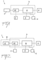
Figure 1 is a scheme of a general example of a device for powering and controlling an electric vehicle, according to the present invention; -
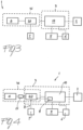
Figure 2 is a scheme of a first particular example of a device for powering and controlling an electric vehicle, according to the present invention; -
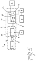
Figure 3 is a scheme of a second particular example of a device for powering and controlling an electric vehicle, according to the present invention; -
Figure 4 is a scheme of a third particular example of a device for powering and controlling an electric vehicle, according to the present invention; -
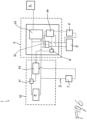
Figure 5 is a scheme of a fourth particular example of a device for powering and controlling an electric vehicle, according to the present invention; -
Figure 6 is a scheme of a fifth particular example of a device for powering and controlling an electric vehicle, according to the present invention. - With reference to the attached figures, in its more general embodiment, the device 1 of the present invention is adapted to powering and controlling an electric vehicle comprising an
electric traction motor 2 and acontrol system 3 of the vehicle and theelectric traction motor 2. Theelectric traction motor 2 provides driving torque to a driven wheel of the vehicle. - The device 1 comprises a first
main battery 4 which is adapted to power theelectric traction motor 2 and thecontrol system 3, in addition to asecond service battery 5 which is adapted to power thecontrol system 3 during an ignition phase of the vehicle. - The device 1 further comprises
first starting means 6 of the vehicle, consisting for example of afirst switch 6 which can be operated by the user by means of an ignition key or ignition push button and second emergency starting means 7 of the vehicle, consisting for example of asecond switch 7 that can be operated by the user by means of an emergency starting push button and positioned on anemergency circuit 71. - One of the particular characteristics of the device 1 according to the present invention is given by the fact that said
control system 3 comprises afirst control unit 10 of the vehicle and of theelectric traction motor 2 and asecond control unit 20 of the firstmain battery 4. - In physical terms, the
first control unit 10 of the vehicle and thesecond control unit 20 of the firstmain battery 4 can be integrated in the same control system 3 (Figure 1 ). Alternatively, thesecond control unit 20 can be advantageously integrated in physical terms in acontrol system 31 of the first main battery 4 (Figures 2-6 ). In turn, thecontrol system 3 of the vehicle and theelectric traction motor 2, and thecontrol system 31 of the firstmain battery 4 can be physically integrated, totally or partially (Figures 2 ,4 and5 ), or physically separated (Figures 3 and6 ). - Another of the particular features of the device 1 according to the present invention is given by the fact that the
first starting switch 6 is operatively connected to saidsecond service battery 5 and to saidfirst control unit 10 of the vehicle and theelectric traction motor 2, in such a way that when it is closed (ignition key set to ON), thefirst control unit 10 is powered by means of thesecond service battery 5 to allow starting of the vehicle. - As better explained below, the second
emergency starting switch 7 is operatively connected to thesecond control unit 20 in such a way to allow powering of thefirst control unit 10 by means of the firstmain battery 4 under emergency conditions, namely when thesecond service battery 5 does not have sufficient charge to permit starting of the vehicle. - With reference to
figures 4-6 , in a preferred embodiment the device 1 for powering and controlling an electric vehicle comprises third switching means 21 which are controlled by thesecond control unit 20 of the firstmain battery 4 and are adapted to connect said firstmain battery 4 to thefirst control unit 10 of the vehicle and theelectric traction motor 2. - The device 1 further comprises fourth switching means 11 which are controlled by the
first control unit 10 of the vehicle and theelectric traction motor 2 and which are operatively connected to saidsecond control unit 20 of said firstmain battery 4. As better explained below, the fourth switching means 11 are adapted to send to the second control unit 20 a signal for the activation/deactivation of said third switching means 21. - In one embodiment of the device of the present invention, the third switching means 21 consist of a switch 21 (main switch) which is controlled by the
BMS 20 of themain battery 4, and allows to connect electrically the power supply of thecontrol system 3 of the vehicle and of theelectric traction motor 2 to the voltage of the firstmain battery 4. In turn, the fourth switching means 11 consist of a further switch 11 (ignition switch) which is controlled by the vehicle control unit (VCU) so that when its closure is detected by theBMS 20, the latter consequently activates closing of themain switch 21, thus starting the vehicle under normal conditions. - Under emergency starting conditions, on the other hand, the second
emergency starting switch 7 is adapted to send to saidsecond control unit 20 of said first main battery 4 a signal for the activation/deactivation of said third switching means 21. The user then, by means of a push button for example, acts on the secondemergency starting switch 7, causing it to close. TheBMS 20 then detects closing of theemergency circuit 71 and activates themain switch 21 causing closure of the powering circuit of thecontrol system 3 of the vehicle and of theelectric traction motor 2 by means of themain battery 4. - In practical terms, the
main switch 21 can advantageously consist of an internal switch of said firstmain battery 4. - As previously mentioned, in the device 1 for powering and controlling an electric vehicle according to the invention, the
main traction battery 4 and thesecond service battery 5 operate at different voltage levels, for example at voltages of 48 V and 12 V respectively. - With reference to
Figures 5 and6 , in an example of the device 1 of the invention, thefirst control unit 10 of the vehicle and theelectric traction motor 2 comprises voltage converter means 12 (in practice, a DC-DC converter) which are interposed between said firstmain battery 4 and saidsecond service battery 5. - In this way it is possible to produce an operative interface between the two
batteries service battery 5 by means of themain battery 4. - Again with reference to
Figures 5 and6 , in an example of the device 1 of the invention, saidfirst control unit 10 of the vehicle and theelectric traction motor 2 comprises first control means 13 of the electric motor (typically a Motor Control Unit - MCU) and second control means 14 of the vehicle (Vehicle Control Unit - VCU). - Typically, the
MCU 13 of theelectric traction motor 2 is operatively connected to the firstmain battery 4 and to saidelectric traction motor 2 so as to allow the driving of saidelectric traction motor 2. - Furthermore, the
VCU 14 of the vehicle is typically operatively connected to saidsecond service battery 5 for starting the vehicle in normal conditions and is operatively connected to said firstmain battery 4 to allow starting of the vehicle under emergency conditions. - In practice, during normal operation the vehicle starting procedure is the following.
- The user operates the first starting means 6, for example by setting the key switch to the ON position. The
VCU 14 is then powered by theservice battery 5 and gives the command for closing theignition switch 11 of themain battery 4 intended mainly for traction. - The
BMS 20 detects closing of theignition contact 11 and activates themain switch 21, connecting the power supply of thecontrol system 3 of the vehicle and of theelectric traction motor 2 to themain battery 4. Once powered, thecontrol system 3 of the vehicle and of theelectric traction motor 2 is able to maintain the charge of theservice battery 5 by means of the DC-DC converter 12 and drive theelectric traction motor 2 by means of theMCU 13. - If the
service battery 5 is flat, it is not possible to power theVCU 14 and proceed with the standard ignition procedure; the emergency starting procedure must be employed by means of theemergency starting switch 7. The emergency starting procedure is the following. - The user operates the first starting means 6, for example by setting the key switch to the ON position. Since the
service battery 5 is flat, theVCU 14 cannot be powered and cannot give the command for closing theignition switch 11 of themain traction battery 4. - At this point the user operates the emergency starting switch 7 (for example by means of a push button) closing the
emergency circuit 71. TheBMS 20 detects closing of theemergency circuit 71 and activates themain switch 21 connecting the power supply of thecontrol system 3 of the vehicle and of theelectric traction motor 2 to themain battery 4. - The
control system 3 of the vehicle and of theelectric traction motor 2, once powered, is able to power theVCU 14 and recharge theservice battery 5 by means of the DC-DC converter 12. TheVCU 14 can then command closing of theignition switch 11 of themain battery 4. - At this point the user can release the push button activating the
emergency starting switch 7. At this point, the vehicle has been started and is in the normal operating mode, with thecontrol system 3 of the vehicle and theelectric traction motor 2 continuing to charge theservice battery 5 by means of the DC-DC converter 12 and at the same time can begin driving theelectric traction motor 2 by means of theMCU 13. - It has been seen in practice that a device for powering and controlling an electric vehicle, and in particular an electric motorcycle, according to the present invention achieves the predefined objects.
- Using the powering and controlling device of the present invention, it is in fact possible to start the vehicle also when the service battery is not sufficiently charged.
- Furthermore, once the vehicle has been started, the powering and controlling device of the present invention allows recharging of the service battery.
- As has been seen from the previous description and attached figures, the powering and controlling device of the present invention can be produced with relatively simple circuit means.
- Furthermore, if the vehicle consists of an electric traction motorcycle, the powering and controlling device of the invention can expediently comprise a push-button operation system positioned close to the main battery and housed in a protected compartment in such a way as not to be freely accessible, other than by the owner/user, for example in an under-saddle compartment of said motorcycle.
Claims (12)
- An electric motorbike comprising an electric traction motor (2) and a control system (3) of the motorbike and of said electric traction motor (2), wherein said electric motorbike comprises a powering and controlling device (1) comprising:a first main battery (4) for supplying said electric traction motor (2) and said control system (3),a second service battery (5) which is adapted to supply said control system (3) during a starting phase of said motorbike, first motorbike starting means (6) and second motorbike emergency starting means (7), wherein said control system (3) comprises a first control unit (10) of the vehicle and of the said electric traction motor (2) and a second control unit (20) of said first main battery (4)said first starting means (6) being operatively connected to said second service battery (5) and said first control unit (10) of the motorbike and said electric traction motor (2) to supply said first control unit (10) through said second service battery (5) under normal conditions,said second motorbike emergency starting means (7) being operatively connected to said second control unit (20) to supply said first control unit (10) through said first main battery (4) in emergency starting conditions, wherein said emergency starting conditions are the conditions in which the second service battery is not provided with sufficient charge to allow starting of the motorbike, wherein said first motorbike starting means (6) comprise a first starting switch and said second motorbike emergency starting means (7) comprise a second emergency starting switch, wherein said first motorbike starting means and said second motorbike emergency starting means can be operated by an user.
- Electric motorbike according to claim 1, characterized in that the device (1) comprises third switching means (21) controlled by said second control unit (20) of said first main battery (4) and adapted to connect said first main battery (4) to the first control unit (10) of the motorbike and of the electric traction motor (2), and fourth switching means (11) controlled by said first control unit (10) of the motorbike and of the electric traction motor (2) and operatively connected to said second control unit (20) of said first main battery (4) and adapted to send to said second control unit (20) a signal for the activation/deactivation of said third switching means (21).
- Electric motorbike according to claim 2, characterized in that said second motorbike emergency starting switch (7) is adapted to send to said second control unit (20) of said first main battery (4) a signal for activating/deactivating said third switching means (21).
- Electric motorbike (1) according to claim 2 or 3, characterized in that said third switching means (21) comprise an internal switch of said first main battery (4).
- Electric motorbike, according to anyone of the previous claims, characterized in that said first main battery (4) and said second service battery (5) operate at different voltage levels.
- Electric motorbike according to claim 5, characterized in that said first control unit (10) of the motorbike and of said electric traction motor (2) comprises voltage converter means (12) interposed between said first main battery (4) and said second service battery (5).
- Electric motorbike according to anyone of the preceding claims, characterized in that said first control unit (10) of the motorbike and of the electric traction motor (2) comprises first control means (13) of said traction electric motor (2) and second control means (14) of the motorbike.
- Electric motorbike according to claim 7, characterized in that said first control means (13) of said electric traction motor (2) are operatively connected to said first main battery (4) and to said electric motor (2) for driving said electric traction motor (2).
- Electric motorbike according to claim 7 or 8, characterized in that said second control means (14) of the motorbike are operatively connected to said second service battery (5) for starting the motorbike under normal conditions and operationally connected to said first main battery (4) for starting the motorbike under emergency conditions.
- Electric motorbike according to anyone of the previous claims, characterized in that said first starting switch (6) and said second starting switch (7) are operated by a user.
- Electric motorbike according to anyone of the claims 2 to 10, characterized in that said second switch (7) can be actuated by push-button means.
- Electric motorbike according to anyone of the claims 1-11, characterized in that said second emergency starting switch (7) being positioned in a under-saddle compartment of said motorbike.
Applications Claiming Priority (2)
| Application Number | Priority Date | Filing Date | Title |
|---|---|---|---|
| IT102018000009968A IT201800009968A1 (en) | 2018-10-31 | 2018-10-31 | Power and control device of an electric vehicle |
| PCT/EP2019/079686 WO2020089305A1 (en) | 2018-10-31 | 2019-10-30 | Device for powering and controlling an electric vehicle |
Publications (3)
| Publication Number | Publication Date |
|---|---|
| EP3873772A1 EP3873772A1 (en) | 2021-09-08 |
| EP3873772B1 true EP3873772B1 (en) | 2025-04-09 |
| EP3873772C0 EP3873772C0 (en) | 2025-04-09 |
Family
ID=65409245
Family Applications (1)
| Application Number | Title | Priority Date | Filing Date |
|---|---|---|---|
| EP19802093.5A Active EP3873772B1 (en) | 2018-10-31 | 2019-10-30 | Device for powering and controlling an electric vehicle |
Country Status (6)
| Country | Link |
|---|---|
| EP (1) | EP3873772B1 (en) |
| JP (1) | JP7499263B2 (en) |
| CN (1) | CN112672913B (en) |
| IT (1) | IT201800009968A1 (en) |
| TW (1) | TWI839404B (en) |
| WO (1) | WO2020089305A1 (en) |
Families Citing this family (1)
| Publication number | Priority date | Publication date | Assignee | Title |
|---|---|---|---|---|
| CN112937304B (en) * | 2021-03-09 | 2022-09-13 | 东风柳州汽车有限公司 | Electric motor car low-voltage storage battery insufficient voltage's starting system |
Citations (6)
| Publication number | Priority date | Publication date | Assignee | Title |
|---|---|---|---|---|
| EP1137150A2 (en) * | 2000-03-22 | 2001-09-26 | Volkswagen Aktiengesellschaft | Dual battery system |
| JP3687409B2 (en) * | 1999-04-26 | 2005-08-24 | トヨタ自動車株式会社 | Vehicle power supply control device |
| WO2012060766A1 (en) * | 2010-11-01 | 2012-05-10 | Scania Cv Ab | Activation device and activation method for a dual-battery system |
| EP2587618A2 (en) * | 2011-10-27 | 2013-05-01 | Sanyo Electric Co. Ltd | Car power source apparatus and vehicle equipped with the power source apparatus |
| WO2013141808A1 (en) * | 2012-03-23 | 2013-09-26 | Scania Cv Ab | Device and method for emergency start of a vehicle |
| US20150298631A1 (en) * | 2012-11-12 | 2015-10-22 | Siemens Aktiengesellschaft | Electric transportation means, associated method and associated rechargeable battery |
Family Cites Families (13)
| Publication number | Priority date | Publication date | Assignee | Title |
|---|---|---|---|---|
| US5842534A (en) * | 1995-05-31 | 1998-12-01 | Frank; Andrew A. | Charge depletion control method and apparatus for hybrid powered vehicles |
| JP3622501B2 (en) * | 1998-05-21 | 2005-02-23 | マツダ株式会社 | Control device for hybrid vehicle |
| CA2320003C (en) * | 1999-09-22 | 2006-03-21 | Honda Giken Kogyo Kabushiki Kaisha | Control apparatus for hybrid vehicles |
| EP2154028B8 (en) | 2003-02-17 | 2015-12-09 | Denso Corporation | Vehicle power supply system |
| JP3875208B2 (en) * | 2003-04-11 | 2007-01-31 | 日本車輌製造株式会社 | Hybrid vehicle emergency driving system |
| DE102007052750A1 (en) * | 2007-11-06 | 2009-05-07 | Robert Bosch Gmbh | Starting procedure for hybrid drives |
| JP5889750B2 (en) * | 2012-08-10 | 2016-03-22 | 株式会社デンソー | Vehicle power supply system |
| WO2014196242A1 (en) * | 2013-06-07 | 2014-12-11 | 日産自動車株式会社 | Hybrid vehicle control device |
| US20140375066A1 (en) * | 2013-06-19 | 2014-12-25 | Tai-Her Yang | Combustion and emergency start controlling device having auxiliary power source and system thereof |
| US20140375067A1 (en) * | 2013-06-19 | 2014-12-25 | Tai-Her Yang | Combustion and emergency start controlling device with separated-type auxiliary power source and system thereof |
| FR3028683B1 (en) * | 2014-11-17 | 2017-12-29 | Lohr Electromecanique | METHOD FOR RECHARGING ENERGY ACCUMULATION MEANS EQUIPPED WITH AN ELECTRIC OR HYBRID VEHICLE |
| CN206327165U (en) * | 2016-12-05 | 2017-07-14 | 姚立和 | Electric vehicle emergency start device |
| TWI757391B (en) * | 2016-12-14 | 2022-03-11 | 印度商Tvs電機股份有限公司 | A system to control a hybrid vehicle and a method thereof |
-
2018
- 2018-10-31 IT IT102018000009968A patent/IT201800009968A1/en unknown
-
2019
- 2019-10-30 WO PCT/EP2019/079686 patent/WO2020089305A1/en not_active Ceased
- 2019-10-30 TW TW108139296A patent/TWI839404B/en active
- 2019-10-30 CN CN201980059530.4A patent/CN112672913B/en active Active
- 2019-10-30 JP JP2021547929A patent/JP7499263B2/en active Active
- 2019-10-30 EP EP19802093.5A patent/EP3873772B1/en active Active
Patent Citations (6)
| Publication number | Priority date | Publication date | Assignee | Title |
|---|---|---|---|---|
| JP3687409B2 (en) * | 1999-04-26 | 2005-08-24 | トヨタ自動車株式会社 | Vehicle power supply control device |
| EP1137150A2 (en) * | 2000-03-22 | 2001-09-26 | Volkswagen Aktiengesellschaft | Dual battery system |
| WO2012060766A1 (en) * | 2010-11-01 | 2012-05-10 | Scania Cv Ab | Activation device and activation method for a dual-battery system |
| EP2587618A2 (en) * | 2011-10-27 | 2013-05-01 | Sanyo Electric Co. Ltd | Car power source apparatus and vehicle equipped with the power source apparatus |
| WO2013141808A1 (en) * | 2012-03-23 | 2013-09-26 | Scania Cv Ab | Device and method for emergency start of a vehicle |
| US20150298631A1 (en) * | 2012-11-12 | 2015-10-22 | Siemens Aktiengesellschaft | Electric transportation means, associated method and associated rechargeable battery |
Also Published As
| Publication number | Publication date |
|---|---|
| CN112672913B (en) | 2025-03-11 |
| CN112672913A (en) | 2021-04-16 |
| JP7499263B2 (en) | 2024-06-13 |
| TWI839404B (en) | 2024-04-21 |
| JP2022509419A (en) | 2022-01-20 |
| EP3873772A1 (en) | 2021-09-08 |
| WO2020089305A1 (en) | 2020-05-07 |
| IT201800009968A1 (en) | 2020-05-01 |
| EP3873772C0 (en) | 2025-04-09 |
| TW202023855A (en) | 2020-07-01 |
Similar Documents
| Publication | Publication Date | Title |
|---|---|---|
| US12074433B2 (en) | Electric system and method for energizing the electric system | |
| US6323608B1 (en) | Dual voltage battery for a motor vehicle | |
| US8463475B2 (en) | Control device for electric vehicle | |
| JP5201273B2 (en) | Power management device | |
| US9827869B2 (en) | Power supply system and method for an electric vehicle | |
| US8583308B2 (en) | Control device for vehicle | |
| WO2012169023A1 (en) | Vehicle power-supply system, and vehicle | |
| JP2015180140A (en) | Vehicle power supply system | |
| JP2020150629A (en) | DC power supply circuit for work vehicles | |
| JP2018207552A (en) | vehicle | |
| JP2008290513A (en) | Power control device and on-vehicle electronic equipment system | |
| KR20180057231A (en) | Apparatus for preventing trouble of battery | |
| JP2020192866A (en) | Vehicle power control device | |
| JP2015077036A (en) | Electrical power system of vehicle and power supply unit | |
| EP3873772B1 (en) | Device for powering and controlling an electric vehicle | |
| TW201815010A (en) | Motor driving control apparatus and electrically assisted vehicle | |
| CN115431769A (en) | Electric commercial vehicle and low-voltage power supply system thereof | |
| KR20180008976A (en) | System for protecting battery from over-charge for vehicle and the controlling method | |
| JP2020063007A (en) | Vehicle backup power supply device | |
| JP2022509419A5 (en) | ||
| US20220194261A1 (en) | Method and system for activating an electric vehicle | |
| JP2004098921A (en) | Vehicle power management device | |
| US20090174254A1 (en) | Pulse-width modulation rectifier having an emergency generator operating mode | |
| JP2018129936A (en) | Power system | |
| EP4365393A1 (en) | Electronically controlled door latch |
Legal Events
| Date | Code | Title | Description |
|---|---|---|---|
| STAA | Information on the status of an ep patent application or granted ep patent |
Free format text: STATUS: UNKNOWN |
|
| STAA | Information on the status of an ep patent application or granted ep patent |
Free format text: STATUS: THE INTERNATIONAL PUBLICATION HAS BEEN MADE |
|
| PUAI | Public reference made under article 153(3) epc to a published international application that has entered the european phase |
Free format text: ORIGINAL CODE: 0009012 |
|
| STAA | Information on the status of an ep patent application or granted ep patent |
Free format text: STATUS: REQUEST FOR EXAMINATION WAS MADE |
|
| 17P | Request for examination filed |
Effective date: 20210503 |
|
| AK | Designated contracting states |
Kind code of ref document: A1 Designated state(s): AL AT BE BG CH CY CZ DE DK EE ES FI FR GB GR HR HU IE IS IT LI LT LU LV MC MK MT NL NO PL PT RO RS SE SI SK SM TR |
|
| DAV | Request for validation of the european patent (deleted) | ||
| DAX | Request for extension of the european patent (deleted) | ||
| STAA | Information on the status of an ep patent application or granted ep patent |
Free format text: STATUS: EXAMINATION IS IN PROGRESS |
|
| 17Q | First examination report despatched |
Effective date: 20221129 |
|
| GRAP | Despatch of communication of intention to grant a patent |
Free format text: ORIGINAL CODE: EPIDOSNIGR1 |
|
| STAA | Information on the status of an ep patent application or granted ep patent |
Free format text: STATUS: GRANT OF PATENT IS INTENDED |
|
| INTG | Intention to grant announced |
Effective date: 20241015 |
|
| GRAJ | Information related to disapproval of communication of intention to grant by the applicant or resumption of examination proceedings by the epo deleted |
Free format text: ORIGINAL CODE: EPIDOSDIGR1 |
|
| STAA | Information on the status of an ep patent application or granted ep patent |
Free format text: STATUS: EXAMINATION IS IN PROGRESS |
|
| GRAP | Despatch of communication of intention to grant a patent |
Free format text: ORIGINAL CODE: EPIDOSNIGR1 |
|
| STAA | Information on the status of an ep patent application or granted ep patent |
Free format text: STATUS: GRANT OF PATENT IS INTENDED |
|
| GRAS | Grant fee paid |
Free format text: ORIGINAL CODE: EPIDOSNIGR3 |
|
| GRAA | (expected) grant |
Free format text: ORIGINAL CODE: 0009210 |
|
| STAA | Information on the status of an ep patent application or granted ep patent |
Free format text: STATUS: THE PATENT HAS BEEN GRANTED |
|
| INTG | Intention to grant announced |
Effective date: 20250218 |
|
| AK | Designated contracting states |
Kind code of ref document: B1 Designated state(s): AL AT BE BG CH CY CZ DE DK EE ES FI FR GB GR HR HU IE IS IT LI LT LU LV MC MK MT NL NO PL PT RO RS SE SI SK SM TR |
|
| REG | Reference to a national code |
Ref country code: GB Ref legal event code: FG4D |
|
| REG | Reference to a national code |
Ref country code: CH Ref legal event code: EP |
|
| REG | Reference to a national code |
Ref country code: DE Ref legal event code: R096 Ref document number: 602019068474 Country of ref document: DE |
|
| REG | Reference to a national code |
Ref country code: IE Ref legal event code: FG4D |
|
| U01 | Request for unitary effect filed |
Effective date: 20250422 |
|
| U07 | Unitary effect registered |
Designated state(s): AT BE BG DE DK EE FI FR IT LT LU LV MT NL PT RO SE SI Effective date: 20250428 |
|
| PG25 | Lapsed in a contracting state [announced via postgrant information from national office to epo] |
Ref country code: ES Free format text: LAPSE BECAUSE OF FAILURE TO SUBMIT A TRANSLATION OF THE DESCRIPTION OR TO PAY THE FEE WITHIN THE PRESCRIBED TIME-LIMIT Effective date: 20250409 |
|
| PG25 | Lapsed in a contracting state [announced via postgrant information from national office to epo] |
Ref country code: NO Free format text: LAPSE BECAUSE OF FAILURE TO SUBMIT A TRANSLATION OF THE DESCRIPTION OR TO PAY THE FEE WITHIN THE PRESCRIBED TIME-LIMIT Effective date: 20250709 Ref country code: GR Free format text: LAPSE BECAUSE OF FAILURE TO SUBMIT A TRANSLATION OF THE DESCRIPTION OR TO PAY THE FEE WITHIN THE PRESCRIBED TIME-LIMIT Effective date: 20250710 |
|
| PG25 | Lapsed in a contracting state [announced via postgrant information from national office to epo] |
Ref country code: PL Free format text: LAPSE BECAUSE OF FAILURE TO SUBMIT A TRANSLATION OF THE DESCRIPTION OR TO PAY THE FEE WITHIN THE PRESCRIBED TIME-LIMIT Effective date: 20250409 |
|
| PG25 | Lapsed in a contracting state [announced via postgrant information from national office to epo] |
Ref country code: HR Free format text: LAPSE BECAUSE OF FAILURE TO SUBMIT A TRANSLATION OF THE DESCRIPTION OR TO PAY THE FEE WITHIN THE PRESCRIBED TIME-LIMIT Effective date: 20250409 |
|
| PG25 | Lapsed in a contracting state [announced via postgrant information from national office to epo] |
Ref country code: RS Free format text: LAPSE BECAUSE OF FAILURE TO SUBMIT A TRANSLATION OF THE DESCRIPTION OR TO PAY THE FEE WITHIN THE PRESCRIBED TIME-LIMIT Effective date: 20250709 |
|
| PG25 | Lapsed in a contracting state [announced via postgrant information from national office to epo] |
Ref country code: IS Free format text: LAPSE BECAUSE OF FAILURE TO SUBMIT A TRANSLATION OF THE DESCRIPTION OR TO PAY THE FEE WITHIN THE PRESCRIBED TIME-LIMIT Effective date: 20250809 |
|
| U20 | Renewal fee for the european patent with unitary effect paid |
Year of fee payment: 7 Effective date: 20251030 |
|
| PGFP | Annual fee paid to national office [announced via postgrant information from national office to epo] |
Ref country code: GB Payment date: 20251029 Year of fee payment: 7 |
|
| PG25 | Lapsed in a contracting state [announced via postgrant information from national office to epo] |
Ref country code: SM Free format text: LAPSE BECAUSE OF FAILURE TO SUBMIT A TRANSLATION OF THE DESCRIPTION OR TO PAY THE FEE WITHIN THE PRESCRIBED TIME-LIMIT Effective date: 20250409 |
|
| PG25 | Lapsed in a contracting state [announced via postgrant information from national office to epo] |
Ref country code: CZ Free format text: LAPSE BECAUSE OF FAILURE TO SUBMIT A TRANSLATION OF THE DESCRIPTION OR TO PAY THE FEE WITHIN THE PRESCRIBED TIME-LIMIT Effective date: 20250409 |
|
| PG25 | Lapsed in a contracting state [announced via postgrant information from national office to epo] |
Ref country code: SK Free format text: LAPSE BECAUSE OF FAILURE TO SUBMIT A TRANSLATION OF THE DESCRIPTION OR TO PAY THE FEE WITHIN THE PRESCRIBED TIME-LIMIT Effective date: 20250409 |
|
| PLBE | No opposition filed within time limit |
Free format text: ORIGINAL CODE: 0009261 |
|
| STAA | Information on the status of an ep patent application or granted ep patent |
Free format text: STATUS: NO OPPOSITION FILED WITHIN TIME LIMIT |
|
| REG | Reference to a national code |
Ref country code: CH Ref legal event code: L10 Free format text: ST27 STATUS EVENT CODE: U-0-0-L10-L00 (AS PROVIDED BY THE NATIONAL OFFICE) Effective date: 20260218 |
|
| 26N | No opposition filed |
Effective date: 20260112 |