EP3873626B1 - Sprinkler guard for fire protection sprinkler assemblies - Google Patents
Sprinkler guard for fire protection sprinkler assemblies Download PDFInfo
- Publication number
- EP3873626B1 EP3873626B1 EP19879042.0A EP19879042A EP3873626B1 EP 3873626 B1 EP3873626 B1 EP 3873626B1 EP 19879042 A EP19879042 A EP 19879042A EP 3873626 B1 EP3873626 B1 EP 3873626B1
- Authority
- EP
- European Patent Office
- Prior art keywords
- sprinkler
- cage
- assembly
- guarded
- deflector
- Prior art date
- Legal status (The legal status is an assumption and is not a legal conclusion. Google has not performed a legal analysis and makes no representation as to the accuracy of the status listed.)
- Active
Links
Images


Classifications
-
- B—PERFORMING OPERATIONS; TRANSPORTING
- B05—SPRAYING OR ATOMISING IN GENERAL; APPLYING FLUENT MATERIALS TO SURFACES, IN GENERAL
- B05B—SPRAYING APPARATUS; ATOMISING APPARATUS; NOZZLES
- B05B15/00—Details of spraying plant or spraying apparatus not otherwise provided for; Accessories
- B05B15/14—Arrangements for preventing or controlling structural damage to spraying apparatus or its outlets, e.g. for breaking at desired places; Arrangements for handling or replacing damaged parts
- B05B15/16—Arrangements for preventing or controlling structural damage to spraying apparatus or its outlets, e.g. for breaking at desired places; Arrangements for handling or replacing damaged parts for preventing non-intended contact between spray heads or nozzles and foreign bodies, e.g. nozzle guards
-
- A—HUMAN NECESSITIES
- A62—LIFE-SAVING; FIRE-FIGHTING
- A62C—FIRE-FIGHTING
- A62C31/00—Delivery of fire-extinguishing material
- A62C31/02—Nozzles specially adapted for fire-extinguishing
-
- A—HUMAN NECESSITIES
- A62—LIFE-SAVING; FIRE-FIGHTING
- A62C—FIRE-FIGHTING
- A62C31/00—Delivery of fire-extinguishing material
- A62C31/28—Accessories for delivery devices, e.g. supports
-
- B—PERFORMING OPERATIONS; TRANSPORTING
- B05—SPRAYING OR ATOMISING IN GENERAL; APPLYING FLUENT MATERIALS TO SURFACES, IN GENERAL
- B05B—SPRAYING APPARATUS; ATOMISING APPARATUS; NOZZLES
- B05B15/00—Details of spraying plant or spraying apparatus not otherwise provided for; Accessories
- B05B15/14—Arrangements for preventing or controlling structural damage to spraying apparatus or its outlets, e.g. for breaking at desired places; Arrangements for handling or replacing damaged parts
-
- A—HUMAN NECESSITIES
- A62—LIFE-SAVING; FIRE-FIGHTING
- A62C—FIRE-FIGHTING
- A62C37/00—Control of fire-fighting equipment
- A62C37/08—Control of fire-fighting equipment comprising an outlet device containing a sensor, or itself being the sensor, i.e. self-contained sprinklers
Definitions
- the present invention relates generally to protection devices for installed fire protection sprinklers. More particularly, the present invention is directed to a sprinkler guard for protecting a sprinkler in its installed and operative position.
- automatic fire protection sprinklers include a frame for connection to a supply pipe of firefighting fluid and a deflector member coupled to the frame for distribution of the fluid to address a fire.
- the frame includes a formed body having an internal passageway with a fluid inlet for receipt of the fluid and a fluid outlet defining a discharge orifice from which the fluid is discharged.
- the deflector member is generally affixed at a fixed distance from the fluid outlet by a pair of frame arms that extend from the frame body.
- a boss or enlarged formation for engagement by an installation tool such as a wrench to facilitate sprinkler installation.
- the fluid discharge is automatically controlled by operation of a thermally responsive trigger or actuator that maintains a fluid tight seal at the discharge orifice by, for example, exertion of pressure on a sealing assembly disposed within the outlet.
- a thermally responsive trigger or actuator that maintains a fluid tight seal at the discharge orifice by, for example, exertion of pressure on a sealing assembly disposed within the outlet.
- the trigger operates thereby permitting ejection and release of the sealing assembly and the discharge of fluid through the discharge orifice.
- the discharged fluid impacts the fluid deflection member and is distributed in a designed spray pattern and density in order to effectively address a fire and wet the surrounding area.
- Automatic sprinklers are installed in a variety of environments which can expose the sprinklers to accidental impact and subject them to mechanical damage such as in low elevation or low clearance areas and/or near a high degree of human or mechanical activity.
- storage type automatic sprinklers can be installed in a storage warehouse beneath the warehouse ceiling and above the storage area and commodities to be protected. In the storage environment, stored commodities are stacked and moved by operating personnel or material handling equipment such as forklifts. The movement of material or mechanical equipment proximate to an installed automatic sprinkler exposes the sprinkler to possible accidental impact and damage. If the trigger of the sprinkler is damaged, water may discharge from the sprinkler; or if the deflector or frame is damaged, the sprinkler may not distribute fluid in the proper pattern.
- Sprinkler guards are configured for protecting sprinklers installed in an upright orientation, in which fluid is discharged from the sprinkler body toward the ceiling and then redirected downward by the fluid deflection member toward the protection area.
- Sprinkler guards are also configured for protecting sprinklers installed in a pendent orientation, in which fluid is discharged downward to impact the fluid deflection member for distribution below the sprinkler over the protection area.
- the sprinkler guard includes a cage-like enclosure with one open-ended base. The guard is installed by sliding the guard over the sprinkler through the base so that the sprinkler is coaxially centered within the cage.
- the guard includes a securement assembly that secures the open-ended base of the cage about the sprinkler body against the enlarged boss of the sprinkler body.
- a securement assembly that secures the open-ended base of the cage about the sprinkler body against the enlarged boss of the sprinkler body.
- Illustrative examples of these known sprinkler guards are shown and described in U.S. Patent Nos. 1,469,336 ; 3,797,746 ; 5,632,339 and 5,893,418 .
- Other known sprinkler guards are known from KR 200 454 219 Y1 and KR 101 709 996 B1 .
- the guards are bulky with a profile that is large relative to the sprinkler being protected so as to present an overall guarded sprinkler assembly that can complicate sprinkler installation particularly in low clearance areas and/or or otherwise visibly detract from the surrounding environment.
- the cage volume is relatively large as compared to the securement assembly.
- 1,469,336 ; 3,797,746 and 5,632,339 have a cage that encompasses or circumscribes the deflector member, frame arms and wrench boss.
- the cage of the sprinkler guard extends axially from a distance spaced from the deflector member to a location aligned with the frame body at or below the fluid outlet. Accordingly, for these known sprinkler guards, the internal volume of the cage is relatively large with respect to the sprinkler to encompass or circumscribe the deflector and most if not all of the frame arms.
- Preferred embodiments of a sprinkler guard and guarded sprinkler assembly are provided in which the sprinkler guard includes a preferred cage and securement arrangement that facilitates assembly, handling and installation. Moreover, the preferred sprinkler guard provides for one or more preferred dimensional relationships with respect to the fire protection sprinkler being protected to present a compact assembly that can facilitate installation of a guarded sprinkler assembly in a low clearance area and minimize the space occupied by the guarded sprinkler assembly.
- Preferred embodiments of a sprinkler guard protect a fire protection sprinkler having a frame body and a fluid deflector member affixed to the frame body.
- the sprinkler guard includes a preferred securement assembly and a preferred cage affixed to the securement assembly having a plurality of guard members defining an internal volume centered about a central vertical axis.
- the plurality of guard members having a first portion traversing about the internal volume to define a preferred upper boundary of the cage.
- the plurality of guard members also has a second portion traversing about internal volume to define a preferred lower boundary of the cage.
- the plurality of guard members defining a preferred insertion passageway proximate the lower boundary for receipt of the sprinkler to locate the fluid deflector member of the sprinkler within the internal volume and centered along the vertical axis.
- the preferred sprinkler guard defines one or more dimensional relationships with the sprinkler.
- Preferred dimensional relationships can be defined: (i) wherein a fixed distance between the fluid deflector member and the frame body and a clearance distance from the upper boundary of the cage to the deflector define a ratio of fixed distance-to-clearance distance (H1:H2) that ranges from 1:1 to 2:1; (ii) wherein a deflector diameter of the fluid deflector member and the clearance distance define a ratio of defector diameter-to-clearance distance (Dia:H2) that ranges from 1.8:1 to 2:1; (iii) wherein a cage diameter of the cage and the deflector diameter define a ratio of cage diameter-to-deflector diameter (WCGE:Dia) that ranges from 1:7 to 2:1; and (iv) wherein the fluid deflector member is affixed to the frame body by a pair of frame arms having an arm width therebetween and an opening width of the insertion passageway and the arm width define a ratio of opening width-to-arm width (WOPN:WARM) that ranges from 1:1 to 1.2
- Preferred embodiments of a sprinkler guard include a cage and a clamp assembly secured to and preferably riveted to the cage to define a preferred hinged arrangement.
- the preferred clamp assembly locates operational components of a sprinkler within the cage.
- the preferred hinge arrangement maintains the cage and clamp assembly connected to one another when handling and installing the guard about a sprinkler thereby minimizing the number of separate components to be handled during an installation of the guard about a sprinkler.
- the clamp assembly engages the sprinkler in a preferred manner that provides rigidity to the guarded sprinkler assembly.
- the cage defines a preferred profile about the sprinkler that is compact and in close proximity to the fluid deflecting components of the sprinkler without negatively impacting the firefighting and water distribution functions of the sprinkler.
- a preferred embodiment of a fire protection sprinkler guard includes a wire cage that defines an internal volume centered about a central axis.
- the cage includes a plurality of terminal wire free end portions that are preferably aligned in a plane.
- a clamp assembly is affixed to the cage in which the clamp assembly has a first clamp member and a second clamp member which define a hinged relationship aligned in the first plane.
- the hinged relationship has an open state to define an opening to the cage for locating operational components of the sprinkler in the internal volume.
- the hinged relationship has a closed state to define a plurality of compartments for housing the wire free end portions.
- the guarded sprinkler assembly includes a sprinkler having a frame with a body defining an inlet, an outlet and an internal passageway extending between the inlet and outlet along a sprinkler axis.
- the body includes a wrench boss formed about the outlet with an external thread about the body for coupling to fluid supply pipe.
- the frame includes a pair of frame arms formed about the sprinkler body and disposed in a first plane. The frame arms extend from the sprinkler body away from the outlet in the direction of the sprinkler axis and a deflector member is coupled to the frame arms to be located axially from the body at fixed distance and centered on the sprinkler axis.
- the deflector has a periphery defining an outer diameter of the deflector.
- a wire cage is disposed about the sprinkler to define an internal volume axially aligned with the sprinkler axis with operational components of the fire sprinkler located within the internal volume.
- the cage includes a plurality of terminal wire free end portions aligned in the first plane.
- a clamp assembly is affixed to the cage.
- the clamp assembly has a first clamp member and a second clamp member which define a hinged relationship with the cage that is aligned in the first plane such that at least one of the first and second clamp members pivot with respect to the first plane to provide access to a cage opening.
- the hinged relationship has an open state to define access for locating the operational components of the sprinkler in the internal volume and the hinged relationship has a closed state to restrict the cage opening and define a plurality of compartments for housing the wire free end portions.
- FIG. 1 and 2A-2D are various views of a guarded sprinkler assembly that includes a preferred embodiment of a sprinkler protective housing or guard 10.
- the guard 10 includes a preferred cage 12 and a securement assembly preferably embodied as a clamping assembly 14 for securely placing the protective housing about a fire protection sprinkler as illustrated, for example, in FIGS. 2A and 2B .
- the cage 12 defines an internal volume 16 about a central vertical axis A--A for housing operational components of the fire sprinkler.
- the cage 12 includes a plurality of guard members 20, 30a, 30b arranged and affixed to one another about the central vertical axis A--A with a circumscribing member 40 to define the perimeter and bounds of the internal volume 16 of the cage 12 including a lower boundary 12a and an upper boundary 12b.
- the geometry and spacing between the guard members 20, 30a, 30b define a preferred insertion passageway or opening 10a proximate the lower boundary 12a of the cage 12 for inserting a sprinkler 100 into the cage 12 to locate operational components of the sprinkler within the protective internal volume 16 of the cage 12.
- the guard member spacing minimizes or eliminates the stress, distortion or deflection on the guard members 20, 30a, 30b when inserting the sprinkler into the cage 12.
- the preferred clamp assembly 14 is preferably secured to the cage 12 to define a preferred hinged arrangement or relationship that limits or restricts the insertion passageway to secure the sprinkler guard 10 to the sprinkler.
- the preferred hinge arrangement maintains the cage 12 and clamp assembly 14 connected to one another when handling and installing the guard about a sprinkler thereby minimizing the number of separate components to be handled during an installation process.
- the clamp assembly 14 engages the frame of the sprinkler in a preferred manner that provides rigidity to the guarded sprinkler assembly. Because the sprinkler guard 10 provides protection to an installed sprinkler, the guard 10 does not negatively impact the fluid distribution and firefighting function of the sprinkler.
- the cage 12 defines a preferred profile that is compact and in close proximity to the fluid deflecting components of the sprinkler without negatively impacting the function of the sprinkler.
- the first guard member 20 is disposed in a first plane P1 with the second guard member 30a and the third member 30b extending parallel to a second plane P2 which extends perpendicular to and intersects the first plane P1 to define a central vertical axis A--A of the guard 10.
- Each of the guard members 20, 30a, 30b and the circumscribing member 40 are preferably formed from a metal wire or rod member of suitable gauge to provide protection to the sprinkler.
- a preferred wire metal wire is about 0.1 inch (2.54 mm) and more preferably 0.09 inch (2.29 mm) in diameter steel wire.
- the first guard member 20 is preferably formed with a central portion 22 having a pair of terminal end portions 24a, 24b equidistantly spaced apart from one another about and extending to one side of the central portion 22.
- the central horizontal portion 22 intersects the central axis A--A in the first plane P1 with the pair of terminal end portions 24a, 24b equidistantly spaced apart from one another about the central vertical axis A--A.
- the first guard member 20 includes two portions disposed about the central vertical axis A--A with each of the two portions extending between the horizontal portion 22 and one of the terminal end portions 24a, 24b to define a first pair of perimeter posts 26a, 26b of the cage.
- each of the second and third guard members 30a, 30b are affixed to the horizontal portion 22 of the first guard member 20 by welding or brazing such that the central posts 34 of the second and third guard members 30a, 30b are disposed in the first plane P1 in general planar alignment with the terminal end portions 24a, 24b of the first guard member 20.
- portions of the second and third guard members 30a, 30b are disposed radially from the central vertical axis A--A to define a second pair of perimeter posts 38a, 38b and a third pair of perimeter posts 38c, 38d.
- each of the perimeter posts 26a, 26b, 38a, 38b, 38c, 38d extends axially parallel to the central vertical axis A--A with the first pair of perimeter posts 26a, 26b preferably disposed in the first plane P1.
- the perimeter posts can define alternate geometries in traversing about the internal volume 16 in the direction from the clamp assembly 14 toward the preferred central horizontal portion 22 of the first guard member 20.
- the perimeter of the cage 12 is preferably circular with the perimeter posts 26a, 26b, 38a, 38b, 38c, 38d or portions thereof spaced equidistantly from the central vertical axis A--A of the cage 12.
- the circumscribing member 40 is preferably of a circular geometry and consists of a single circular member in tangential contact with the perimeter posts 26a, 26b, 38a, 38b, 38c, 38d.
- the preferred clamp assembly 14 affixed to the cage 12 preferably includes a first clamp member 14a and a second clamp member 14b to define a preferred hinged relationship or arrangement 50 with respect to one another about one of the terminal end portions 24b of the first guard member 20. More preferably, the terminal end portion 24b forms a pin about which each of the clamp member 14a, 14b rotate. In a preferred embodiment, the terminal end portion 24b is preferably deformed or staked to form a rivet to secure the clamp members 14a, 14b in the hinged relationship.
- the hinged relationship has an open state, shown in FIG. 1 , to provide access to the cage opening 10a and the internal volume 16 for insertion, removal or adjustment of a sprinkler within the cage 12.
- the hinged relationship 50 has a closed state, as seen in FIG. 2A-2C , to restrict the cage opening 10a and define a plurality of compartments 15a, 15b, 15c for housing the central posts 34 of the second and third guard members 30a, 30b and the other of the terminal end portions 24a of the first guard member 20 opposite the hinged relationship 50.
- the first and second clamp members 14a, 14b include bearing plates 60a, 60b opposed to one another about the first plane P1.
- the clamp members 14a, 14b and the bearing plates 60a, 60b defining a preferred arched or arcuate geometry for securement about a fire sprinkler body.
- Preferably respectively formed at one end of each of the clamp members 14a, 14b is a knuckle 52a, 52b for receipt of the terminal end portion 24b of the first guard member 20 as a pin to form the preferred hinged relationship 50.
- the hinge arrangement 50 is axially disposed between the arcuate bearing plates 60a, 60b and the horizontal portion 22 of the first guard member 20.
- Each of the opposed arcuate bearing plates include one or more clip formations or members 62 to secure the arcuate bearing plates to the sprinkler body.
- Preferred embodiments of the arcuate bearing plates 60a, 60b also include a plurality of bracing members that extend from each of the bearing plates in the direction of the vertical central axis to contact the sprinkler frame in a preferred manner as described herein to stiffen and provide rigidity to the guarded sprinkler assembly.
- the plurality of bracing members 64 preferably has four bracing members in which each arcuate bearing plate 60a, 60b includes two bracing members about the second plane P2 intersecting and perpendicular to the first plane P1. As seen in FIG.
- the configuration of the clamp assembly 14 locates the compartments 15b, 15c for receipt of the central posts 34 of the second and third guard members 30a, 30b laterally about the respective arcuate bearing plates 60a, 60b and in alignment with the first plane P1.
- the guard 10 can be disposed over and about an illustrative embodiment of a fire protection sprinkler 100 having a frame 105.
- the frame 105 includes a frame body 110 having an inlet 112, an outlet 114 aligned with one another along a longitudinal sprinkler axis X--X.
- the preferred frame 105 includes a pair of frame arms 120 to support and locate a deflector 200 at a fixed distance along the longitudinal sprinkler axis from the sprinkler body 110 and the outlet 114.
- Firefighting fluid is delivered to the sprinkler inlet 112 at a working pressure and discharged from the outlet 114 to impact the deflector for distribution in an expected density and/or geometry about the guarded sprinkler assembly.
- the outer surface of the sprinkler body 110 is configured for connecting the sprinkler 10 to a fluid supply pipe.
- the body 110 can include an external male pipe thread 111.
- Preferred embodiments of the external male pipe thread 111 include a nominal 1/2 inch-14 NPT. Larger threaded connection can include nominal 3/4 inch-14 NPT pipe.
- the sprinkler body 110 includes a wrench boss 118 with a preferably hexagonal perimeter disposed about the outlet 114 and centered about the sprinkler axis X--X to provide two or more flat surfaces for engagement by an installation tool, such as for example, a sprinkler installation wrench.
- the clamp assembly 14 and its arcuate bearing plates 60a, 60b can wrap about and preferably bear against the sprinkler body 110 between the wrench boss 118 and the external thread 111.
- the clip members 62 are preferably dimensioned to define a recess sufficient to accommodate the thickness or height of the wrench boss 118 and secure the clamp assembly 14 about the sprinkler body 110 as seen, for example, in FIGS. 2A and 2B .
- the pair of frame arms 120 of the sprinkler frame 105 extend from the body 110 at diametrically opposed sides of the outlet 114 and converge toward one another to form and/or support a deflector boss 122 that is centered along the sprinkler axis X--X for support of the deflector 200 at the fixed distance from the outlet 114.
- Each of the frame arms 120 has a peripheral surface 124 and an interior surface 126 with respect to the sprinkler axis X--X with the interior surface 126 being closest to or confronting the longitudinal axis X--X.
- the peripheral and interior surfaces 124, 126 extend from the body 110 to the boss 122 to define the frame arm profile.
- Each of the frame arms 120 includes a transition surface 128 that extends between the peripheral surface 124 and the interior surface 126. Individually and/or collectively the peripheral and transition surfaces 124, 128 define one or more surfaces against which the bracing members 64 of the clamp assembly 14 can form a surface contact engagement or embrace to stabilize the sprinkler guard 10 about the sprinkler frame 105 and provide rigidity to the assembly as seen for example in FIGS. 2A-2D .
- the ends 24a, 34 of the guard members 20, 30a, 30b are received in the compartments of the closed compartments 15a, 15b, 15c of the clamp assembly 14.
- the clamp members 14a, 14b can be secured to one another by an appropriate fastening device 17 such as for example a screw and nut assembly (not shown).
- the clamp assembly 14 engages the sprinkler frame arms 120 in a manner that orients the frame 105 to locate the frame arms 120 in the first plane P1 of the guard 10 aligned with the compartments 15a, 15b, 15c and hinge 50.
- the spaced apart bracing members 64 expose a sufficient portion of the wrench boss 118 to allow for tool access in order to adjust connection of the sprinkler to a fluid supply pipe with the guard 10 installed.
- the sprinkler guard 10 protects the operative components of the sprinkler 100 in the installed and operative position of the sprinkler.
- the operative components can include a fluid deflecting member or deflector 200 and/or a thermally responsive actuating device 500.
- Preferred embodiments of the sprinkler 10, are preferably configured as automatic sprinklers such that fluid discharge from the connected sprinkler 10 and its outlet 114 is controlled by a seal assembly 400 that is disposed within the passageway 116 proximate the outlet 114 as seen in FIG. 2A to occlude the outlet 114.
- the seal assembly 400 is maintained within outlet 114 of the sprinkler body 110 by the thermally responsive element or trigger 500 preferably aligned along the sprinkler axis X--X between the sealing assembly 400 and the deflector 200.
- the guard 10 preferably engages the sprinkler 100 such that the sprinkler axis X--X coaxially aligns with the sprinkler guard axis A--A so as to center the thermally responsive element 500 in the cage 12 and maximize the protection about the trigger 500.
- the thermally responsive element 500 is preferably embodied as a thermally responsive frangible glass bulb, as seen in FIG. 1 , but can be alternatively embodied as a thermally responsive soldered assembly, or mechanical or electrically actuated assembly provided the assembly can seat and unseat the seal assembly 400 in respective unactuated and actuated states of the sprinkler.
- the thermally responsive element 500 operates or triggers to release the sealing assembly 400 and permit the supplied firefighting fluid to discharge from the outlet 114 to impact the deflector 200 for distribution of the fluid in a desired manner to address a fire.
- the guard 10 engages a sprinkler in its installed and operative position in a manner that protects the deflector 200 but minimizes or eliminates any negative impact on the fluid distribution function.
- the deflector 200 is illustratively shown bent or formed for installation in an upright orientation in which supplied firefighting fluid is discharged from the outlet 114 to impact the deflector 200 in an upward direction.
- the affixed deflector can be formed or configured for a pendent orientation in which fluid is discharged in a downward direction or in a sidewall orientation in which water is discharged horizontally.
- the deflector 200 is affixed to the boss 122 to locate the deflector 200 at a first fixed distance from the body 110.
- the deflector 200 is located at a fixed distance H1 from the region between the boss 118 and the external thread 111 against which the bearing plates 60a, 60b bear of the clamp assembly 14.
- the deflector 200 is located at a preferred fixed distance from one or more features or structures of the sprinkler guard 10.
- the deflector 200 is located at a preferred second fixed distance H2 from the central portion 22 of the first guard member 20.
- the second fixed distance H2 defines the clearance above the deflector 200 and indirectly defines the clearance below the deflector 200 within the internal volume 16 of the cage 12 to manipulate and position the sprinkler 100 and its deflector to secure the guard 10 about the sprinkler 200.
- the second fixed distance H2 defines a preferred profile of the cage 12 about the deflector 200 that is compact enough to protect the deflector yet not interfere with the distribution function of the deflector while exposing the other portions of the sprinkler frame 105 to install or loosen the sprinkler 100 from the fluid supply piping with the sprinkler guard 10 on.
- the cage 12 and the perimeter posts 26a, 26b, 38a, 38c, 38d define the preferably circular perimeter and preferred radial clearance about the deflector 200.
- the sprinkler 100 and the guard 10 define one or more preferred dimensional relationships.
- the sprinkler guard 10 defines a preferred overall or maximum height HGT of about 2.25 inches (57.15 mm) preferably measured from the central portion 22 to the bearing plates 60a, 60b of the clamp assembly 14.
- the clamp assembly 14 has a preferred height HCLMP of about 0.75 inch (19.05 mm) to provide for a cage height HCAG of about 1.5 inch (38.1 mm).
- a preferred cage height-to-clamp height ratio (HCAG:HCLMP) is about 2:1 with the maximum guard height-to-cage height ratio (HGT:HCAG) being about 1.5:1. Any approximated preferred dimension as an about value herein could vary up to 10%.
- the clearance distance H2 can be equal to the deflector-to-body distance H1 and is more preferably less than the deflector-to-body distance H1. In a preferred embodiment of the sprinkler 100 in which the deflector-to-body distance H1 is about 1.5 (38.1 mm), the clearance distance H2 is preferably about 0.75 inch (19.05 mm).
- a preferred deflector-to-body distance H1-to-clearance H2 ratio is about 2:1.
- a deflector-to-body distance H1-to-clearance H2 ratio (H1:H2) that can be any one of 1.5:1 or 1:1 or any ratio in between 1:1 to 2:1.
- the deflector 200 defines a preferred deflector diameter Dia to clearance H2 ratio (Dia:H2) that preferably ranges from 1.8:1 to 2.1:1 and is preferably about 2:1 where preferred deflectors 200 define an outer diameter Dia that ranges from 1.4-1.6 inch (35.56-40.64 mm).
- the preferably circular cage 12 defines a cage diameter or width WCGE.
- the cage diameter WCGE is about 2.75 inches (69.85 mm).
- a preferred cage-to-deflector diameter ratio ranges from about 1.7:1 to about 2:1.
- the spacing between the second and third guard members 30a, 30b preferably define the cage opening 10a for insertion of the sprinkler operational components.
- the opening 10a defines a preferred maximum width WOPN, as seen in FIG. 2C , between the central posts 34 of the second and third guard members 30a, 30b.
- the central posts 34 can be free for displacement to define a resiliently variable width WOPN in order to expand the cage opening for sprinkler insertion.
- the central posts 34 of the second and guard members can be fixed with respect to one another to define a fixed width WOPN opening in which to insert a sprinkler.
- the central posts 34 can be fixed to one of the clamp members 14a, 14b.
- the width WOPN of the cage opening 10a is preferably equal to or smaller than the deflector diameter Dia. More preferably, the width WOPN of the cage opening 10a is preferably equal to or slightly greater than the span or width WARM between the maximum peripheral surfaces 124 of the frame arms 120 of the sprinkler 100 to stiffen and/or compact the guarded assembly in the closed state of the clamp assembly 14.
- the ratio of the cage opening-to-arm width preferably ranges from 1.1:1 to 1.2:1.
- the traversing portions extend preferably perpendicular to the first plane P1. Accordingly, in a preferred profile embodiment of the cage 12, the lower end perimeter or boundary 12a of the cage 12 is axially located between the deflector member 200 and the frame body 110 of the sprinkler 100 and more preferably axially spaced from the fluid outlet 114 of the frame body 110.
- each of the guard members 20, 30a, 30b have portions that traverse the internal volume 16 above the deflector 200.
- the traversing portion of each guard members 20, 30a, 30b that extends between central horizontal portion 22 and their respective vertical perimeter posts is preferably sloped or skewed with respect to the first and second planes P1, P2.
- the upper boundary 12b of the cage defines a preferably frustoconical framework.
- the upper boundary 12b of the cage 12 can support a water shield 600 for shielding a guarded sprinkler from water discharge from surrounding sprinklers in a fire protection installation.
- a guarded sprinkler assembly can be in an installed operative location that is below sprinklers located at a higher elevation.
- Fire protection applications that may require water shielding include in-rack storage sprinkler systems, under grating, on pilot sprinklers for deluge systems, and outdoors as a weather shield. Water discharged from the higher sprinklers may impact the thermally responsive trigger 500 of the guarded sprinkler and prevent its proper thermal response.
- a water shield disposed atop the sprinkler guard 10 can prevent higher elevation water droplets from impacting the guarded sprinkler and its trigger 500.
- the water shield 600 is preferably frustoconical in shape to fit atop the frustoconical upper boundary 12b of the cage 12.
- the inner surface of the shield 600 includes one or more preferably integrally formed hooks or clips 602 for engaging guard members of the cage 12 of the sprinkler guard.
Landscapes
- Health & Medical Sciences (AREA)
- Public Health (AREA)
- Business, Economics & Management (AREA)
- Emergency Management (AREA)
- Fire-Extinguishing By Fire Departments, And Fire-Extinguishing Equipment And Control Thereof (AREA)
Description
- The present invention relates generally to protection devices for installed fire protection sprinklers. More particularly, the present invention is directed to a sprinkler guard for protecting a sprinkler in its installed and operative position.
- Generally, automatic fire protection sprinklers include a frame for connection to a supply pipe of firefighting fluid and a deflector member coupled to the frame for distribution of the fluid to address a fire. The frame includes a formed body having an internal passageway with a fluid inlet for receipt of the fluid and a fluid outlet defining a discharge orifice from which the fluid is discharged. The deflector member is generally affixed at a fixed distance from the fluid outlet by a pair of frame arms that extend from the frame body. Externally formed about the sprinkler body proximate the outlet is a boss or enlarged formation for engagement by an installation tool such as a wrench to facilitate sprinkler installation. In an automatic sprinkler, the fluid discharge is automatically controlled by operation of a thermally responsive trigger or actuator that maintains a fluid tight seal at the discharge orifice by, for example, exertion of pressure on a sealing assembly disposed within the outlet. When the temperature surrounding the sprinkler is elevated within a range of the nominal temperature rating of the trigger, the trigger operates thereby permitting ejection and release of the sealing assembly and the discharge of fluid through the discharge orifice. The discharged fluid impacts the fluid deflection member and is distributed in a designed spray pattern and density in order to effectively address a fire and wet the surrounding area. Several factors can influence the water distribution patterns of a sprinkler including, for example, the installation orientation and the geometry of the fluid deflection member, the distance between the deflection member and the discharge orifice, and/or the shape of the sprinkler frame to which the deflection member is coupled. Accordingly, the fluid control, distribution and performance of an automatic sprinkler is dependent upon the integrity of the sprinkler assembly and its individual components.
- Automatic sprinklers are installed in a variety of environments which can expose the sprinklers to accidental impact and subject them to mechanical damage such as in low elevation or low clearance areas and/or near a high degree of human or mechanical activity. For example, storage type automatic sprinklers can be installed in a storage warehouse beneath the warehouse ceiling and above the storage area and commodities to be protected. In the storage environment, stored commodities are stacked and moved by operating personnel or material handling equipment such as forklifts. The movement of material or mechanical equipment proximate to an installed automatic sprinkler exposes the sprinkler to possible accidental impact and damage. If the trigger of the sprinkler is damaged, water may discharge from the sprinkler; or if the deflector or frame is damaged, the sprinkler may not distribute fluid in the proper pattern.
- It is well known to use a sprinkler guard to protect an installed sprinkler. Sprinkler guards are configured for protecting sprinklers installed in an upright orientation, in which fluid is discharged from the sprinkler body toward the ceiling and then redirected downward by the fluid deflection member toward the protection area. Sprinkler guards are also configured for protecting sprinklers installed in a pendent orientation, in which fluid is discharged downward to impact the fluid deflection member for distribution below the sprinkler over the protection area. Generally, the sprinkler guard includes a cage-like enclosure with one open-ended base. The guard is installed by sliding the guard over the sprinkler through the base so that the sprinkler is coaxially centered within the cage. The guard includes a securement assembly that secures the open-ended base of the cage about the sprinkler body against the enlarged boss of the sprinkler body. Illustrative examples of these known sprinkler guards are shown and described in
U.S. Patent Nos. 1,469,336 ;3,797,746 ;5,632,339 and5,893,418 . Other known sprinkler guards are known fromKR 200 454 219 Y1 KR 101 709 996 B1 - Although these cage-like enclosures can protect a sprinkler, the guards are bulky with a profile that is large relative to the sprinkler being protected so as to present an overall guarded sprinkler assembly that can complicate sprinkler installation particularly in low clearance areas and/or or otherwise visibly detract from the surrounding environment. In the known sprinkler guards of
U.S. Patent Nos. 1,469,336 ;3,797,746 ;5,632,339 and5,893,418 , the cage volume is relatively large as compared to the securement assembly. For example, the sprinkler guards in each ofU.S. Patent Nos. 1,469,336 ;3,797,746 and5,632,339 have a cage that encompasses or circumscribes the deflector member, frame arms and wrench boss. In each of the known sprinkler guards ofU.S. Patent Nos. 1,469,336 ;3,797,746 ;5,632,339 and5,893,418 , the cage of the sprinkler guard extends axially from a distance spaced from the deflector member to a location aligned with the frame body at or below the fluid outlet. Accordingly, for these known sprinkler guards, the internal volume of the cage is relatively large with respect to the sprinkler to encompass or circumscribe the deflector and most if not all of the frame arms. There thus remains a need for a sprinkler guard and guarded sprinkler assembly with a compact profile that sufficiently protects the critical operating components of a fire protection sprinkler and that can be used in low clearance areas and/or otherwise minimize any visible detraction from the surrounding environment. Moreover, there remains a need for sprinkler guards that can be assembled over a fire protection sprinkler either prior to sprinkler installation or thereafter. - Preferred embodiments of a sprinkler guard and guarded sprinkler assembly are provided in which the sprinkler guard includes a preferred cage and securement arrangement that facilitates assembly, handling and installation. Moreover, the preferred sprinkler guard provides for one or more preferred dimensional relationships with respect to the fire protection sprinkler being protected to present a compact assembly that can facilitate installation of a guarded sprinkler assembly in a low clearance area and minimize the space occupied by the guarded sprinkler assembly.
- Preferred embodiments of a sprinkler guard protect a fire protection sprinkler having a frame body and a fluid deflector member affixed to the frame body. The sprinkler guard includes a preferred securement assembly and a preferred cage affixed to the securement assembly having a plurality of guard members defining an internal volume centered about a central vertical axis. The plurality of guard members having a first portion traversing about the internal volume to define a preferred upper boundary of the cage. The plurality of guard members also has a second portion traversing about internal volume to define a preferred lower boundary of the cage. The plurality of guard members defining a preferred insertion passageway proximate the lower boundary for receipt of the sprinkler to locate the fluid deflector member of the sprinkler within the internal volume and centered along the vertical axis. The preferred sprinkler guard defines one or more dimensional relationships with the sprinkler. Preferred dimensional relationships can be defined: (i) wherein a fixed distance between the fluid deflector member and the frame body and a clearance distance from the upper boundary of the cage to the deflector define a ratio of fixed distance-to-clearance distance (H1:H2) that ranges from 1:1 to 2:1; (ii) wherein a deflector diameter of the fluid deflector member and the clearance distance define a ratio of defector diameter-to-clearance distance (Dia:H2) that ranges from 1.8:1 to 2:1; (iii) wherein a cage diameter of the cage and the deflector diameter define a ratio of cage diameter-to-deflector diameter (WCGE:Dia) that ranges from 1:7 to 2:1; and (iv) wherein the fluid deflector member is affixed to the frame body by a pair of frame arms having an arm width therebetween and an opening width of the insertion passageway and the arm width define a ratio of opening width-to-arm width (WOPN:WARM) that ranges from 1:1 to 1.2:1.
- Preferred embodiments of a sprinkler guard include a cage and a clamp assembly secured to and preferably riveted to the cage to define a preferred hinged arrangement. In preferred guarded sprinkler assemblies, the preferred clamp assembly locates operational components of a sprinkler within the cage. The preferred hinge arrangement maintains the cage and clamp assembly connected to one another when handling and installing the guard about a sprinkler thereby minimizing the number of separate components to be handled during an installation of the guard about a sprinkler. In addition to securing the cage about the sprinkler, the clamp assembly engages the sprinkler in a preferred manner that provides rigidity to the guarded sprinkler assembly. The cage defines a preferred profile about the sprinkler that is compact and in close proximity to the fluid deflecting components of the sprinkler without negatively impacting the firefighting and water distribution functions of the sprinkler.
- A preferred embodiment of a fire protection sprinkler guard includes a wire cage that defines an internal volume centered about a central axis. The cage includes a plurality of terminal wire free end portions that are preferably aligned in a plane. A clamp assembly is affixed to the cage in which the clamp assembly has a first clamp member and a second clamp member which define a hinged relationship aligned in the first plane. The hinged relationship has an open state to define an opening to the cage for locating operational components of the sprinkler in the internal volume. The hinged relationship has a closed state to define a plurality of compartments for housing the wire free end portions.
- According to the invention, the guarded sprinkler assembly includes a sprinkler having a frame with a body defining an inlet, an outlet and an internal passageway extending between the inlet and outlet along a sprinkler axis. The body includes a wrench boss formed about the outlet with an external thread about the body for coupling to fluid supply pipe. The frame includes a pair of frame arms formed about the sprinkler body and disposed in a first plane. The frame arms extend from the sprinkler body away from the outlet in the direction of the sprinkler axis and a deflector member is coupled to the frame arms to be located axially from the body at fixed distance and centered on the sprinkler axis. The deflector has a periphery defining an outer diameter of the deflector. A wire cage is disposed about the sprinkler to define an internal volume axially aligned with the sprinkler axis with operational components of the fire sprinkler located within the internal volume. The cage includes a plurality of terminal wire free end portions aligned in the first plane. A clamp assembly is affixed to the cage. The clamp assembly has a first clamp member and a second clamp member which define a hinged relationship with the cage that is aligned in the first plane such that at least one of the first and second clamp members pivot with respect to the first plane to provide access to a cage opening. The hinged relationship has an open state to define access for locating the operational components of the sprinkler in the internal volume and the hinged relationship has a closed state to restrict the cage opening and define a plurality of compartments for housing the wire free end portions.
- The accompanying drawings, which are incorporated herein and constitute part of this specification, illustrate exemplary embodiments of the invention, and together, with the general description given above and the detailed description given below, serve to explain the features of the invention. It should be understood that the preferred embodiments are some examples of the invention as provided by the appended claims.
-
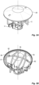
FIG. 1 is an exploded view of one preferred embodiment of a guarded sprinkler assembly having a preferred sprinkler guard. -
FIGS. 2A-2B are front and side elevation views of a preferred embodiment of the guarded sprinkler assembly ofFIG. 1 , -
FIGS. 2C-2D are plan end views of the guarded sprinkler assembly ofFIG. 2A . -
FIGS. 3A-3B are various perspective views of a shielded sprinkler guard using the sprinkler guard ofFIG. 1 . - Shown in
FIG. 1 and2A-2D are various views of a guarded sprinkler assembly that includes a preferred embodiment of a sprinkler protective housing orguard 10. Theguard 10 includes apreferred cage 12 and a securement assembly preferably embodied as a clampingassembly 14 for securely placing the protective housing about a fire protection sprinkler as illustrated, for example, inFIGS. 2A and 2B . Thecage 12 defines aninternal volume 16 about a central vertical axis A--A for housing operational components of the fire sprinkler. Thecage 12 includes a plurality ofguard members member 40 to define the perimeter and bounds of theinternal volume 16 of thecage 12 including alower boundary 12a and anupper boundary 12b. The geometry and spacing between theguard members opening 10a proximate thelower boundary 12a of thecage 12 for inserting asprinkler 100 into thecage 12 to locate operational components of the sprinkler within the protectiveinternal volume 16 of thecage 12. In preferred embodiments of thecage 12, the guard member spacing minimizes or eliminates the stress, distortion or deflection on theguard members cage 12. - The
preferred clamp assembly 14 is preferably secured to thecage 12 to define a preferred hinged arrangement or relationship that limits or restricts the insertion passageway to secure thesprinkler guard 10 to the sprinkler. The preferred hinge arrangement maintains thecage 12 and clampassembly 14 connected to one another when handling and installing the guard about a sprinkler thereby minimizing the number of separate components to be handled during an installation process. In addition to securing thecage 12 about the sprinkler, theclamp assembly 14 engages the frame of the sprinkler in a preferred manner that provides rigidity to the guarded sprinkler assembly. Because thesprinkler guard 10 provides protection to an installed sprinkler, theguard 10 does not negatively impact the fluid distribution and firefighting function of the sprinkler. In addition, thecage 12 defines a preferred profile that is compact and in close proximity to the fluid deflecting components of the sprinkler without negatively impacting the function of the sprinkler. - In the preferred embodiments of the
cage 12, thefirst guard member 20 is disposed in a first plane P1 with thesecond guard member 30a and thethird member 30b extending parallel to a second plane P2 which extends perpendicular to and intersects the first plane P1 to define a central vertical axis A--A of theguard 10. Each of theguard members member 40 are preferably formed from a metal wire or rod member of suitable gauge to provide protection to the sprinkler. A preferred wire metal wire is about 0.1 inch (2.54 mm) and more preferably 0.09 inch (2.29 mm) in diameter steel wire. Thefirst guard member 20 is preferably formed with acentral portion 22 having a pair ofterminal end portions central portion 22. In theguard 10, the centralhorizontal portion 22 intersects the central axis A--A in the first plane P1 with the pair ofterminal end portions first guard member 20 includes two portions disposed about the central vertical axis A--A with each of the two portions extending between thehorizontal portion 22 and one of theterminal end portions perimeter posts - In the
cage 12, thesecond guard member 30a and athird guard member 30b are in a preferably fixed spaced apart relationship from one another equidistantly about the central vertical axis A--A to define the preferred cage insertion passageway oropening 10a for inserting operational components of a sprinkler into the cage. The wire forming second andthird guard members central post 34 of theguard members FIG. 2D , the closed form of eachguard member cage 12, each of the second andthird guard members horizontal portion 22 of thefirst guard member 20 by welding or brazing such that thecentral posts 34 of the second andthird guard members terminal end portions first guard member 20. - In the cage formation, portions of the second and
third guard members perimeter posts perimeter posts perimeter posts perimeter posts internal volume 16 in the direction from theclamp assembly 14 toward the preferred centralhorizontal portion 22 of thefirst guard member 20. The perimeter of thecage 12 is preferably circular with theperimeter posts cage 12. In such a preferred embodiment of thecage 12, the circumscribingmember 40 is preferably of a circular geometry and consists of a single circular member in tangential contact with theperimeter posts - The
preferred clamp assembly 14 affixed to thecage 12 preferably includes afirst clamp member 14a and asecond clamp member 14b to define a preferred hinged relationship orarrangement 50 with respect to one another about one of theterminal end portions 24b of thefirst guard member 20. More preferably, theterminal end portion 24b forms a pin about which each of theclamp member terminal end portion 24b is preferably deformed or staked to form a rivet to secure theclamp members FIG. 1 , to provide access to thecage opening 10a and theinternal volume 16 for insertion, removal or adjustment of a sprinkler within thecage 12. The hingedrelationship 50 has a closed state, as seen inFIG. 2A-2C , to restrict thecage opening 10a and define a plurality ofcompartments central posts 34 of the second andthird guard members terminal end portions 24a of thefirst guard member 20 opposite the hingedrelationship 50. - In the closed state of the
clamp assembly 14, the first andsecond clamp members bearing plates clamp members bearing plates clamp members knuckle terminal end portion 24b of thefirst guard member 20 as a pin to form the preferred hingedrelationship 50. In the preferred configuration of thesprinkler guard 10, thehinge arrangement 50 is axially disposed between thearcuate bearing plates horizontal portion 22 of thefirst guard member 20. Each of the opposed arcuate bearing plates include one or more clip formations ormembers 62 to secure the arcuate bearing plates to the sprinkler body. Preferred embodiments of thearcuate bearing plates members 64 preferably has four bracing members in which eacharcuate bearing plate FIG. 2C , the configuration of theclamp assembly 14 locates thecompartments central posts 34 of the second andthird guard members arcuate bearing plates - Shown in
FIG. 1 and the open state of theclamp assembly 14, theguard 10 can be disposed over and about an illustrative embodiment of afire protection sprinkler 100 having aframe 105. Theframe 105 includes aframe body 110 having aninlet 112, anoutlet 114 aligned with one another along a longitudinal sprinkler axis X--X. Thepreferred frame 105 includes a pair offrame arms 120 to support and locate adeflector 200 at a fixed distance along the longitudinal sprinkler axis from thesprinkler body 110 and theoutlet 114. - Firefighting fluid is delivered to the
sprinkler inlet 112 at a working pressure and discharged from theoutlet 114 to impact the deflector for distribution in an expected density and/or geometry about the guarded sprinkler assembly. The outer surface of thesprinkler body 110 is configured for connecting thesprinkler 10 to a fluid supply pipe. For example, thebody 110 can include an external male pipe thread 111. Preferred embodiments of the external male pipe thread 111 include a nominal 1/2 inch-14 NPT. Larger threaded connection can include nominal 3/4 inch-14 NPT pipe. To facilitate securement of thesprinkler 110 to a fluid pipe fitting such as, for example a tee fitting or union, thesprinkler body 110 includes awrench boss 118 with a preferably hexagonal perimeter disposed about theoutlet 114 and centered about the sprinkler axis X--X to provide two or more flat surfaces for engagement by an installation tool, such as for example, a sprinkler installation wrench. - To secure the
sprinkler guard 10 to thesprinkler 100, theclamp assembly 14 and itsarcuate bearing plates sprinkler body 110 between thewrench boss 118 and the external thread 111. Moreover, theclip members 62 are preferably dimensioned to define a recess sufficient to accommodate the thickness or height of thewrench boss 118 and secure theclamp assembly 14 about thesprinkler body 110 as seen, for example, inFIGS. 2A and 2B . - Referring again to
FIG. 1 , the pair offrame arms 120 of thesprinkler frame 105 extend from thebody 110 at diametrically opposed sides of theoutlet 114 and converge toward one another to form and/or support adeflector boss 122 that is centered along the sprinkler axis X--X for support of thedeflector 200 at the fixed distance from theoutlet 114. Each of theframe arms 120 has aperipheral surface 124 and aninterior surface 126 with respect to the sprinkler axis X--X with theinterior surface 126 being closest to or confronting the longitudinal axis X--X. The peripheral andinterior surfaces body 110 to theboss 122 to define the frame arm profile. Each of theframe arms 120 includes atransition surface 128 that extends between theperipheral surface 124 and theinterior surface 126. Individually and/or collectively the peripheral and transition surfaces 124, 128 define one or more surfaces against which the bracingmembers 64 of theclamp assembly 14 can form a surface contact engagement or embrace to stabilize thesprinkler guard 10 about thesprinkler frame 105 and provide rigidity to the assembly as seen for example inFIGS. 2A-2D . - In the closed state of the
clamp assembly 14 about thesprinkler 100, theends guard members closed compartments clamp assembly 14. Theclamp members appropriate fastening device 17 such as for example a screw and nut assembly (not shown). In the preferred guarded sprinkler assembly, theclamp assembly 14 engages thesprinkler frame arms 120 in a manner that orients theframe 105 to locate theframe arms 120 in the first plane P1 of theguard 10 aligned with thecompartments hinge 50. The spaced apart bracingmembers 64 expose a sufficient portion of thewrench boss 118 to allow for tool access in order to adjust connection of the sprinkler to a fluid supply pipe with theguard 10 installed. - The
sprinkler guard 10 protects the operative components of thesprinkler 100 in the installed and operative position of the sprinkler. The operative components can include a fluid deflecting member ordeflector 200 and/or a thermallyresponsive actuating device 500. Preferred embodiments of thesprinkler 10, are preferably configured as automatic sprinklers such that fluid discharge from the connectedsprinkler 10 and itsoutlet 114 is controlled by aseal assembly 400 that is disposed within the passageway 116 proximate theoutlet 114 as seen inFIG. 2A to occlude theoutlet 114. Theseal assembly 400 is maintained withinoutlet 114 of thesprinkler body 110 by the thermally responsive element or trigger 500 preferably aligned along the sprinkler axis X--X between the sealingassembly 400 and thedeflector 200. Theguard 10 preferably engages thesprinkler 100 such that the sprinkler axis X--X coaxially aligns with the sprinkler guard axis A--A so as to center the thermallyresponsive element 500 in thecage 12 and maximize the protection about thetrigger 500. - The thermally
responsive element 500 is preferably embodied as a thermally responsive frangible glass bulb, as seen inFIG. 1 , but can be alternatively embodied as a thermally responsive soldered assembly, or mechanical or electrically actuated assembly provided the assembly can seat and unseat theseal assembly 400 in respective unactuated and actuated states of the sprinkler. In the presence of a sufficient level of heat, the thermallyresponsive element 500 operates or triggers to release the sealingassembly 400 and permit the supplied firefighting fluid to discharge from theoutlet 114 to impact thedeflector 200 for distribution of the fluid in a desired manner to address a fire. Accordingly, theguard 10 engages a sprinkler in its installed and operative position in a manner that protects thedeflector 200 but minimizes or eliminates any negative impact on the fluid distribution function. - The
deflector 200 is illustratively shown bent or formed for installation in an upright orientation in which supplied firefighting fluid is discharged from theoutlet 114 to impact thedeflector 200 in an upward direction. Alternatively, the affixed deflector can be formed or configured for a pendent orientation in which fluid is discharged in a downward direction or in a sidewall orientation in which water is discharged horizontally. Thedeflector 200 is affixed to theboss 122 to locate thedeflector 200 at a first fixed distance from thebody 110. For example, thedeflector 200 is located at a fixed distance H1 from the region between theboss 118 and the external thread 111 against which thebearing plates clamp assembly 14. Accordingly, in the guarded sprinkler assembly, thedeflector 200 is located at a preferred fixed distance from one or more features or structures of thesprinkler guard 10. For example, thedeflector 200 is located at a preferred second fixed distance H2 from thecentral portion 22 of thefirst guard member 20. In one preferred aspect, the second fixed distance H2 defines the clearance above thedeflector 200 and indirectly defines the clearance below thedeflector 200 within theinternal volume 16 of thecage 12 to manipulate and position thesprinkler 100 and its deflector to secure theguard 10 about thesprinkler 200. In another preferred aspect, the second fixed distance H2 defines a preferred profile of thecage 12 about thedeflector 200 that is compact enough to protect the deflector yet not interfere with the distribution function of the deflector while exposing the other portions of thesprinkler frame 105 to install or loosen thesprinkler 100 from the fluid supply piping with thesprinkler guard 10 on. Moreover, thecage 12 and theperimeter posts deflector 200. - Accordingly, in the preferred guarded sprinkler assembly, the
sprinkler 100 and theguard 10 define one or more preferred dimensional relationships. For example, in one preferred embodiment with reference toFIG. 2A , thesprinkler guard 10 defines a preferred overall or maximum height HGT of about 2.25 inches (57.15 mm) preferably measured from thecentral portion 22 to thebearing plates clamp assembly 14. Theclamp assembly 14 has a preferred height HCLMP of about 0.75 inch (19.05 mm) to provide for a cage height HCAG of about 1.5 inch (38.1 mm). - Thus, a preferred cage height-to-clamp height ratio (HCAG:HCLMP) is about 2:1 with the maximum guard height-to-cage height ratio (HGT:HCAG) being about 1.5:1. Any approximated preferred dimension as an about value herein could vary up to 10%. The clearance distance H2 can be equal to the deflector-to-body distance H1 and is more preferably less than the deflector-to-body distance H1. In a preferred embodiment of the
sprinkler 100 in which the deflector-to-body distance H1 is about 1.5 (38.1 mm), the clearance distance H2 is preferably about 0.75 inch (19.05 mm). - Accordingly, a preferred deflector-to-body distance H1-to-clearance H2 ratio (H1:H2) is about 2:1. Alternate embodiments can provide for a deflector-to-body distance H1-to-clearance H2 ratio (H1:H2) that can be any one of 1.5:1 or 1:1 or any ratio in between 1:1 to 2:1. In another preferred relationship of the guarded sprinkler assembly, the
deflector 200 defines a preferred deflector diameter Dia to clearance H2 ratio (Dia:H2) that preferably ranges from 1.8:1 to 2.1:1 and is preferably about 2:1 wherepreferred deflectors 200 define an outer diameter Dia that ranges from 1.4-1.6 inch (35.56-40.64 mm). - As seen in
FIG. 2D , the preferablycircular cage 12 defines a cage diameter or width WCGE. For the preferred deflector diameter Dia, the cage diameter WCGE is about 2.75 inches (69.85 mm). - Accordingly, a preferred cage-to-deflector diameter ratio (WCGE:Dia) ranges from about 1.7:1 to about 2:1.
- As previously noted and with reference to
FIG. 1 , the spacing between the second andthird guard members cage opening 10a for insertion of the sprinkler operational components. With theclamp assembly 14 in its open state, theopening 10a defines a preferred maximum width WOPN, as seen inFIG. 2C , between thecentral posts 34 of the second andthird guard members clamp assembly 14, thecentral posts 34 can be free for displacement to define a resiliently variable width WOPN in order to expand the cage opening for sprinkler insertion. Alternatively, thecentral posts 34 of the second and guard members can be fixed with respect to one another to define a fixed width WOPN opening in which to insert a sprinkler. For example, thecentral posts 34 can be fixed to one of theclamp members - With reference to
FIGS. 2C and 2D , shown are additional preferred dimensional relationships between thesprinkler 100 and theguard 10. For thedeflector 200 and its outer perimeter or periphery defining an outer diameter Dia, the width WOPN of thecage opening 10a is preferably equal to or smaller than the deflector diameter Dia. More preferably, the width WOPN of thecage opening 10a is preferably equal to or slightly greater than the span or width WARM between the maximumperipheral surfaces 124 of theframe arms 120 of thesprinkler 100 to stiffen and/or compact the guarded assembly in the closed state of theclamp assembly 14. In one preferred dimensional relationship between thesprinkler 100 and theguard 10, the ratio of the cage opening-to-arm width (WOPN:WARM) preferably ranges from 1.1:1 to 1.2:1. - Preferably, each of the
guard members internal volume 16 in a manner to define the lower end perimeter orboundary 12a of the preferred profile of thecage 12 and the opposite upper end perimeter orboundary 12b of the preferred profile of thecage 12 with the upper boundary opposite theclamp assembly 14 and the lower boundary between theupper boundary 12a and theclamp assembly 14. With reference toFIGS. 2B and2C , each of theguard members internal volume 16 between thedeflector 200 and theoutlet 114 of thesprinkler frame 105 just outside theframe arms 120 to define thelower boundary 12a of thecage 12. Moreover, portions of theguard members internal volume 16 below thedeflector 200 inside the deflector perimeter and diameter Dia. The traversing portions extend preferably perpendicular to the first plane P1. Accordingly, in a preferred profile embodiment of thecage 12, the lower end perimeter orboundary 12a of thecage 12 is axially located between thedeflector member 200 and theframe body 110 of thesprinkler 100 and more preferably axially spaced from thefluid outlet 114 of theframe body 110. - At the
upper boundary 12b of the cage, each of theguard members internal volume 16 above thedeflector 200. With reference toFIGS. 2A and 2B , the traversing portion of eachguard members horizontal portion 22 and their respective vertical perimeter posts is preferably sloped or skewed with respect to the first and second planes P1, P2. Accordingly, theupper boundary 12b of the cage defines a preferably frustoconical framework. Referring now toFIGS. 3A and 3B , theupper boundary 12b of thecage 12 can support awater shield 600 for shielding a guarded sprinkler from water discharge from surrounding sprinklers in a fire protection installation. More specifically, a guarded sprinkler assembly can be in an installed operative location that is below sprinklers located at a higher elevation. Fire protection applications that may require water shielding include in-rack storage sprinkler systems, under grating, on pilot sprinklers for deluge systems, and outdoors as a weather shield. Water discharged from the higher sprinklers may impact the thermallyresponsive trigger 500 of the guarded sprinkler and prevent its proper thermal response. Accordingly, a water shield disposed atop thesprinkler guard 10 can prevent higher elevation water droplets from impacting the guarded sprinkler and itstrigger 500. Thewater shield 600 is preferably frustoconical in shape to fit atop the frustoconicalupper boundary 12b of thecage 12. To secure theshield 600 to thecage 12, the inner surface of theshield 600 includes one or more preferably integrally formed hooks orclips 602 for engaging guard members of thecage 12 of the sprinkler guard. - While the present invention has been disclosed with reference to certain embodiments, numerous modifications, alterations, and changes to the described embodiments are possible without departing from the scope of the present invention, as defined in the appended claims. Accordingly, it is intended that the present invention not be limited to the described embodiments, but that it has the full scope defined by the language of the following claims.
Claims (15)
- A guarded sprinkler assembly comprising:a sprinkler (100) including:a frame (105) including a body (110) defining an inlet (112), an outlet (114) and an internal passageway (116) extending between the inlet (112) and outlet (114) along a sprinkler axis, the body (110) including a wrench boss (118) formed about the outlet (114) and an external thread (111) about the body (110) for coupling to fluid supply pipe, the frame (105) including a pair of frame arms (120) formed about the sprinkler body and disposed in a first plane (P1), the frame arms (120) extending from the sprinkler body away from the outlet (114) in the direction of the sprinkler axis; anda deflector member (200) coupled to the frame arms (120) located axially from the body (110) at fixed distance and centered on the sprinkler axis, the deflector (200) having a periphery defining an outer diameter of the deflector (200);a wire cage (12) disposed about the sprinkler (100) defining an internal volume (16) axially aligned with the sprinkler axis with operational components of the fire sprinkler (100) located within the internal volume (16), the cage (12) including a plurality of terminal wire free end portions (24a, 24b, 34) anda clamp assembly (14) affixed to the cage (12),the clamp assembly (14) having a first clamp member (14a) and a second clamp member (14b) which define a hinged relationship (50) with the cage (12) aligned in the first plane (P1) such that at least one of the first and second clamp members (14a, 14b) pivot with respect to the first plane (P1) to provide access to a cage opening (10a),the hinged relationship (50) having an open state to define access for locating the operational components of the sprinkler (100) in the internal volume (16), the hinged relationship (50) having a closed state to restrict the cage opening,characterized in thatthe plurality of terminal wire free end portions is aligned in the first plane, andthe closed state of the hinged relationship defines a plurality of compartments (15a, 15b, 15c) for housing the wire free end portions.
- The guarded sprinkler assembly of claim 1, wherein the hinged relationship (50) includes a terminal end portion (24b) of the wire cage (12) forming a pin of the hinge arrangement and wherein each of the first and second clamp members (14a, 14b) forming knuckles (52a, 52b) of the hinge arrangement.
- The guarded sprinkler assembly of claim 2, wherein the cage (12) includes a plurality of perimeter posts (26a, 26b, 38a, 38b, 38c, 38d) radially disposed about the sprinkler (100), a wire (40) circumscribed about the plurality of perimeter posts (26a, 26b, 38a, 38b, 38c, 38d).
- The guarded sprinkler assembly of claim 3, wherein the plurality of perimeter posts (26a, 26b, 38a, 38b, 38c, 38d) includes a pair of posts (26a, 26b) oppositely disposed about the sprinkler (100) in the first plane (P1).
- The guarded sprinkler assembly of claim 3, wherein the plurality perimeter posts (26a, 26b, 38a, 38b, 38c, 38d) include six perimeter posts, the wire (40) consisting of a single wire circumscribed about the six posts.
- The guarded sprinkler assembly of claim 3, wherein the cage (12) includes portions traversing from the perimeter posts (26a, 26b, 38a, 38b, 38c, 38d) across the internal volume (16) to define opposed end perimeters (12a, 12b) of the cage (12), wherein preferably, one end perimeter (12a) of the cage (12) is axially located between the deflector member (200) and the outlet (114) of the sprinkler (100).
- The guarded sprinkler assembly of any one of the preceding claims, wherein the closed state of the clamp assembly (14), the first and second clamp members (14a, 14b) include two arcuate bearing plates (60a, 60b) opposed to one another about the first plane (P1) for engagement about a sprinkler body (110) defining an outlet (114) of the sprinkler (100), each of the opposed arcuate bearing plates (60a, 60b) include clip members (62) to secure the arcuate bearing plates (60a, 60b) to the wrench boss (118), each of the opposed arcuate bearing plates (60a, 60b) include a plurality of bracing members (64) that extend from the bearing plates (60a, 60b) to brace against the frame arms (120) of the sprinkler frame (105).
- The guarded sprinkler assembly of claim 7, wherein the plurality of bracing members (64) includes four bracing members, each arcuate bearing plate (60a, 60b) including two bearing plates about a second plane (P2) intersecting and perpendicular to the first plane (P1).
- The guarded sprinkler assembly of any one of claims 1 to 8, wherein the cage (12) includes a first guard member (20) including a horizontal portion (22) intersecting the sprinkler axis disposed in the first plane (P1) and a first pair of perimeter posts (26a, 26b) of the cage (12) extending from the horizontal portion (22); the cage (12) including a second guard member (30a) and a third guard member (30b) in a fixed spaced apart relationship from one another equidistantly about the sprinkler (100), each of the second and third guard members (30a, 30b) defining a closed form with a central post (34) defining two of the plurality of terminal wire free end portions (24a, 24b, 34) disposed in the first plane (P1), the closed form of the second and third guard members (30a, 30b) defining a second pair of perimeter posts (38a, 38b) and a third pair of perimeter posts (38c, 38d) of the cage.
- The guarded sprinkler assembly of claim 9, wherein each of the second (30a) and third guard members (30b) include a first portion and a second portion each traversing at least a portion of the internal volume (16) to define an upper boundary (12b) opposite the clamp assembly (14) and a lower boundary (12a) of the cage (12) between the upper boundary (12b) and the clamp assembly (14).
- The guarded sprinkler assembly of claim 10, wherein the upper boundary (12b) is frustoconical, the wire cage (12) including a frustoconical water shield (600) disposed atop the cage (12).
- The guarded sprinkler assembly of any one of claim 1 to 11, wherein the guard defines a cage height-to-clamp assembly height ratio (HCAG:HCLMP) of 2:1.
- The guarded sprinkler assembly of claim 12, wherein the cage (12) has an upper boundary (12b) to define a clearance distance (H2) to the deflector (200), the fixed distance (H1) of the deflector (200) to the sprinkler body (110) defining a fixed distance-to-clearance ratio (H1:H2) of about 2:1.
- The guarded sprinkler assembly of claim 13, wherein the deflector (200) defines a diameter (Dia) and a deflector diameter-to-clearance ratio (Dia:H2) of 2:1.
- The guarded sprinkler assembly of claim 14, wherein the deflector defines a diameter (Dia) and the cage (12) defines a diameter (WGCE), the ratio of cage diameter-to-deflector diameter (WGCE:Dia) ranges from 1.7:1 to 2:1.
Applications Claiming Priority (2)
| Application Number | Priority Date | Filing Date | Title |
|---|---|---|---|
| US201862751954P | 2018-10-29 | 2018-10-29 | |
| PCT/US2019/058309 WO2020092215A1 (en) | 2018-10-29 | 2019-10-28 | Sprinkler guard for fire protection sprinkler assemblies |
Publications (3)
| Publication Number | Publication Date |
|---|---|
| EP3873626A1 EP3873626A1 (en) | 2021-09-08 |
| EP3873626A4 EP3873626A4 (en) | 2022-07-27 |
| EP3873626B1 true EP3873626B1 (en) | 2025-04-16 |
Family
ID=70464602
Family Applications (1)
| Application Number | Title | Priority Date | Filing Date |
|---|---|---|---|
| EP19879042.0A Active EP3873626B1 (en) | 2018-10-29 | 2019-10-28 | Sprinkler guard for fire protection sprinkler assemblies |
Country Status (4)
| Country | Link |
|---|---|
| US (2) | US11260415B2 (en) |
| EP (1) | EP3873626B1 (en) |
| CN (1) | CN217661206U (en) |
| WO (1) | WO2020092215A1 (en) |
Families Citing this family (5)
| Publication number | Priority date | Publication date | Assignee | Title |
|---|---|---|---|---|
| US20240009496A1 (en) * | 2021-01-19 | 2024-01-11 | Mark Stephen Ouellette | Nonobstructive protective housing for sprinkler head |
| WO2024015334A1 (en) * | 2022-07-15 | 2024-01-18 | Minimax Viking Research & Development Gmbh | A protection and installation device for fire protection sprinklers |
| CN113209527A (en) * | 2021-05-22 | 2021-08-06 | 安徽农业大学 | Uniform spraying spray head |
| US12589404B2 (en) | 2021-08-18 | 2026-03-31 | Minimax Viking Patent Management Gmbh | Temporary protective device for fire protection sprinklers |
| CN114231888B (en) * | 2021-12-15 | 2023-09-12 | 无锡进源科技开发有限公司 | Thermal spraying equipment for spraying inner wall of workpiece |
Family Cites Families (16)
| Publication number | Priority date | Publication date | Assignee | Title |
|---|---|---|---|---|
| US1469336A (en) * | 1921-07-01 | 1923-10-02 | Globe Automatic Sprinkler Co | Sprinkler guard |
| US3797746A (en) * | 1972-08-17 | 1974-03-19 | Hodgman Mfg Co Inc | Sprinkler guard |
| US4951755A (en) * | 1989-08-31 | 1990-08-28 | Automatic Sprinkler Corporation Of America | Manual actuator |
| US5632339A (en) | 1995-02-10 | 1997-05-27 | Star Sprinkler Corporation | Fire protection sprinkler head with spaced zones for mounting a protective guard and for connecting the sprinkler head to a water supply line |
| US5893418A (en) | 1997-12-15 | 1999-04-13 | The Reliable Automatic Sprinkler Co., Inc. | Sprinkle guard |
| US20070256844A1 (en) * | 2006-04-20 | 2007-11-08 | Blasing Joseph M | Method and apparatus for lock out-tag out of sprinkler heads |
| KR100821215B1 (en) | 2007-02-14 | 2008-04-11 | 주식회사 동양플렉스 | Head protector for ceiling sprinkler |
| KR20100004181A (en) | 2008-07-03 | 2010-01-13 | 삼성전자주식회사 | Slurry composition for a chemical mechanical polishing, method of preparing the slurry composition and method of polishing an object using the slurry composition |
| KR101063857B1 (en) | 2008-08-13 | 2011-09-08 | (주)화이로 | Bottom-up sprinkler with collector plate |
| KR200451537Y1 (en) * | 2008-10-14 | 2010-12-22 | 주식회사 동양플랙스 | Head protector for ceiling sprinkler |
| KR200454219Y1 (en) * | 2008-12-26 | 2011-06-23 | 주식회사 동양플랙스 | Head protector for ceiling sprinkler |
| US20140361100A1 (en) | 2013-06-10 | 2014-12-11 | Matthew D. Hunsberger | Sprinkler system guard |
| PH12018502123B1 (en) * | 2016-05-10 | 2024-05-15 | Viking Corp | Push on/pull off protective cap for fire protection sprinklers |
| KR101709996B1 (en) | 2017-01-24 | 2017-02-24 | (주)한길엔지니어링 | Sprinkler Head Protection Device for Fire Fighting |
| WO2019090135A1 (en) | 2017-11-03 | 2019-05-09 | Tyco Fire Products Lp | Fire protection sprinkler guard and assembly |
| US10919066B2 (en) * | 2018-06-08 | 2021-02-16 | The Reliable Automatic Sprinkler Co. Inc. | Sprinkler guard and a method of manufacturing a sprinkler guard |
-
2019
- 2019-10-28 WO PCT/US2019/058309 patent/WO2020092215A1/en not_active Ceased
- 2019-10-28 CN CN201990001133.7U patent/CN217661206U/en active Active
- 2019-10-28 US US16/639,306 patent/US11260415B2/en active Active
- 2019-10-28 EP EP19879042.0A patent/EP3873626B1/en active Active
-
2022
- 2022-01-21 US US17/580,761 patent/US11980904B2/en active Active
Also Published As
| Publication number | Publication date |
|---|---|
| US11260415B2 (en) | 2022-03-01 |
| US20210129168A1 (en) | 2021-05-06 |
| US20220219185A1 (en) | 2022-07-14 |
| US11980904B2 (en) | 2024-05-14 |
| EP3873626A1 (en) | 2021-09-08 |
| EP3873626A4 (en) | 2022-07-27 |
| CN217661206U (en) | 2022-10-28 |
| WO2020092215A1 (en) | 2020-05-07 |
Similar Documents
| Publication | Publication Date | Title |
|---|---|---|
| US11980904B2 (en) | Sprinkler guard for fire protection sprinkler assemblies | |
| US11998938B2 (en) | Fire protection sprinkler guard | |
| EP2012880B1 (en) | Extended coverage, storage, automatic fire protection sprinkler | |
| US6805203B2 (en) | Cover plate for concealed sprinkler | |
| EP2012881B1 (en) | Extended coverage horizontal sidewall sprinkler | |
| US11938359B2 (en) | Concealable window sprinkler | |
| US20010042795A1 (en) | Compact pendant sprinkler head | |
| US20210244985A1 (en) | Institutional Sprinklers and Installation Assemblies | |
| EP3610926B1 (en) | Fire suppression sprinkler and deflector | |
| US20200353496A1 (en) | Fire protection sprinkler guard and assembly | |
| TWI891381B (en) | Flush type sprinkler head | |
| WO2026102222A1 (en) | A fire protection system with a shielded automatic fire protection sprinkler | |
| HK1128436B (en) | Extended coverage, storage, automatic fire protection sprinkler | |
| HK1128436A (en) | Extended coverage, storage, automatic fire protection sprinkler | |
| HK1128437B (en) | Extended coverage horizontal sidewall sprinkler |
Legal Events
| Date | Code | Title | Description |
|---|---|---|---|
| STAA | Information on the status of an ep patent application or granted ep patent |
Free format text: STATUS: THE INTERNATIONAL PUBLICATION HAS BEEN MADE |
|
| PUAI | Public reference made under article 153(3) epc to a published international application that has entered the european phase |
Free format text: ORIGINAL CODE: 0009012 |
|
| STAA | Information on the status of an ep patent application or granted ep patent |
Free format text: STATUS: REQUEST FOR EXAMINATION WAS MADE |
|
| 17P | Request for examination filed |
Effective date: 20210531 |
|
| AK | Designated contracting states |
Kind code of ref document: A1 Designated state(s): AL AT BE BG CH CY CZ DE DK EE ES FI FR GB GR HR HU IE IS IT LI LT LU LV MC MK MT NL NO PL PT RO RS SE SI SK SM TR |
|
| DAV | Request for validation of the european patent (deleted) | ||
| DAX | Request for extension of the european patent (deleted) | ||
| REG | Reference to a national code |
Ref country code: DE Ref legal event code: R079 Free format text: PREVIOUS MAIN CLASS: A62C0031000000 Ipc: A62C0031020000 Ref country code: DE Ref legal event code: R079 Ref document number: 602019068842 Country of ref document: DE Free format text: PREVIOUS MAIN CLASS: A62C0031000000 Ipc: A62C0031020000 |
|
| A4 | Supplementary search report drawn up and despatched |
Effective date: 20220629 |
|
| RIC1 | Information provided on ipc code assigned before grant |
Ipc: A62C 37/08 20060101ALI20220623BHEP Ipc: A62C 31/28 20060101ALI20220623BHEP Ipc: A62C 31/02 20060101AFI20220623BHEP |
|
| P01 | Opt-out of the competence of the unified patent court (upc) registered |
Effective date: 20230602 |
|
| RAP1 | Party data changed (applicant data changed or rights of an application transferred) |
Owner name: MINIMAX VIKING PATENT MANAGEMENT GMBH |
|
| GRAP | Despatch of communication of intention to grant a patent |
Free format text: ORIGINAL CODE: EPIDOSNIGR1 |
|
| STAA | Information on the status of an ep patent application or granted ep patent |
Free format text: STATUS: GRANT OF PATENT IS INTENDED |
|
| INTG | Intention to grant announced |
Effective date: 20241202 |
|
| GRAS | Grant fee paid |
Free format text: ORIGINAL CODE: EPIDOSNIGR3 |
|
| GRAA | (expected) grant |
Free format text: ORIGINAL CODE: 0009210 |
|
| STAA | Information on the status of an ep patent application or granted ep patent |
Free format text: STATUS: THE PATENT HAS BEEN GRANTED |
|
| AK | Designated contracting states |
Kind code of ref document: B1 Designated state(s): AL AT BE BG CH CY CZ DE DK EE ES FI FR GB GR HR HU IE IS IT LI LT LU LV MC MK MT NL NO PL PT RO RS SE SI SK SM TR |
|
| REG | Reference to a national code |
Ref country code: GB Ref legal event code: FG4D |
|
| REG | Reference to a national code |
Ref country code: CH Ref legal event code: EP |
|
| REG | Reference to a national code |
Ref country code: IE Ref legal event code: FG4D |
|
| REG | Reference to a national code |
Ref country code: DE Ref legal event code: R096 Ref document number: 602019068842 Country of ref document: DE |
|
| REG | Reference to a national code |
Ref country code: NL Ref legal event code: MP Effective date: 20250416 |
|
| PG25 | Lapsed in a contracting state [announced via postgrant information from national office to epo] |
Ref country code: NL Free format text: LAPSE BECAUSE OF FAILURE TO SUBMIT A TRANSLATION OF THE DESCRIPTION OR TO PAY THE FEE WITHIN THE PRESCRIBED TIME-LIMIT Effective date: 20250416 |
|
| REG | Reference to a national code |
Ref country code: AT Ref legal event code: MK05 Ref document number: 1785182 Country of ref document: AT Kind code of ref document: T Effective date: 20250416 |
|
| PG25 | Lapsed in a contracting state [announced via postgrant information from national office to epo] |
Ref country code: PT Free format text: LAPSE BECAUSE OF FAILURE TO SUBMIT A TRANSLATION OF THE DESCRIPTION OR TO PAY THE FEE WITHIN THE PRESCRIBED TIME-LIMIT Effective date: 20250818 Ref country code: ES Free format text: LAPSE BECAUSE OF FAILURE TO SUBMIT A TRANSLATION OF THE DESCRIPTION OR TO PAY THE FEE WITHIN THE PRESCRIBED TIME-LIMIT Effective date: 20250416 Ref country code: FI Free format text: LAPSE BECAUSE OF FAILURE TO SUBMIT A TRANSLATION OF THE DESCRIPTION OR TO PAY THE FEE WITHIN THE PRESCRIBED TIME-LIMIT Effective date: 20250416 |
|
| REG | Reference to a national code |
Ref country code: LT Ref legal event code: MG9D |
|
| PG25 | Lapsed in a contracting state [announced via postgrant information from national office to epo] |
Ref country code: NO Free format text: LAPSE BECAUSE OF FAILURE TO SUBMIT A TRANSLATION OF THE DESCRIPTION OR TO PAY THE FEE WITHIN THE PRESCRIBED TIME-LIMIT Effective date: 20250716 Ref country code: GR Free format text: LAPSE BECAUSE OF FAILURE TO SUBMIT A TRANSLATION OF THE DESCRIPTION OR TO PAY THE FEE WITHIN THE PRESCRIBED TIME-LIMIT Effective date: 20250717 |
|
| PG25 | Lapsed in a contracting state [announced via postgrant information from national office to epo] |
Ref country code: PL Free format text: LAPSE BECAUSE OF FAILURE TO SUBMIT A TRANSLATION OF THE DESCRIPTION OR TO PAY THE FEE WITHIN THE PRESCRIBED TIME-LIMIT Effective date: 20250416 |
|
| PG25 | Lapsed in a contracting state [announced via postgrant information from national office to epo] |
Ref country code: BG Free format text: LAPSE BECAUSE OF FAILURE TO SUBMIT A TRANSLATION OF THE DESCRIPTION OR TO PAY THE FEE WITHIN THE PRESCRIBED TIME-LIMIT Effective date: 20250416 |
|
| PG25 | Lapsed in a contracting state [announced via postgrant information from national office to epo] |
Ref country code: HR Free format text: LAPSE BECAUSE OF FAILURE TO SUBMIT A TRANSLATION OF THE DESCRIPTION OR TO PAY THE FEE WITHIN THE PRESCRIBED TIME-LIMIT Effective date: 20250416 |
|
| PG25 | Lapsed in a contracting state [announced via postgrant information from national office to epo] |
Ref country code: AT Free format text: LAPSE BECAUSE OF FAILURE TO SUBMIT A TRANSLATION OF THE DESCRIPTION OR TO PAY THE FEE WITHIN THE PRESCRIBED TIME-LIMIT Effective date: 20250416 |
|
| PG25 | Lapsed in a contracting state [announced via postgrant information from national office to epo] |
Ref country code: RS Free format text: LAPSE BECAUSE OF FAILURE TO SUBMIT A TRANSLATION OF THE DESCRIPTION OR TO PAY THE FEE WITHIN THE PRESCRIBED TIME-LIMIT Effective date: 20250716 |
|
| PG25 | Lapsed in a contracting state [announced via postgrant information from national office to epo] |
Ref country code: IS Free format text: LAPSE BECAUSE OF FAILURE TO SUBMIT A TRANSLATION OF THE DESCRIPTION OR TO PAY THE FEE WITHIN THE PRESCRIBED TIME-LIMIT Effective date: 20250816 |
|
| PG25 | Lapsed in a contracting state [announced via postgrant information from national office to epo] |
Ref country code: LV Free format text: LAPSE BECAUSE OF FAILURE TO SUBMIT A TRANSLATION OF THE DESCRIPTION OR TO PAY THE FEE WITHIN THE PRESCRIBED TIME-LIMIT Effective date: 20250416 |
|
| PGFP | Annual fee paid to national office [announced via postgrant information from national office to epo] |
Ref country code: DE Payment date: 20251106 Year of fee payment: 7 |
|
| PGFP | Annual fee paid to national office [announced via postgrant information from national office to epo] |
Ref country code: GB Payment date: 20251024 Year of fee payment: 7 |
|
| PG25 | Lapsed in a contracting state [announced via postgrant information from national office to epo] |
Ref country code: DK Free format text: LAPSE BECAUSE OF FAILURE TO SUBMIT A TRANSLATION OF THE DESCRIPTION OR TO PAY THE FEE WITHIN THE PRESCRIBED TIME-LIMIT Effective date: 20250416 Ref country code: SM Free format text: LAPSE BECAUSE OF FAILURE TO SUBMIT A TRANSLATION OF THE DESCRIPTION OR TO PAY THE FEE WITHIN THE PRESCRIBED TIME-LIMIT Effective date: 20250416 |
|
| REG | Reference to a national code |
Ref country code: DE Ref legal event code: R097 Ref document number: 602019068842 Country of ref document: DE |
|
| PG25 | Lapsed in a contracting state [announced via postgrant information from national office to epo] |
Ref country code: CZ Free format text: LAPSE BECAUSE OF FAILURE TO SUBMIT A TRANSLATION OF THE DESCRIPTION OR TO PAY THE FEE WITHIN THE PRESCRIBED TIME-LIMIT Effective date: 20250416 |
|
| PG25 | Lapsed in a contracting state [announced via postgrant information from national office to epo] |
Ref country code: EE Free format text: LAPSE BECAUSE OF FAILURE TO SUBMIT A TRANSLATION OF THE DESCRIPTION OR TO PAY THE FEE WITHIN THE PRESCRIBED TIME-LIMIT Effective date: 20250416 |
|
| PG25 | Lapsed in a contracting state [announced via postgrant information from national office to epo] |
Ref country code: RO Free format text: LAPSE BECAUSE OF FAILURE TO SUBMIT A TRANSLATION OF THE DESCRIPTION OR TO PAY THE FEE WITHIN THE PRESCRIBED TIME-LIMIT Effective date: 20250416 Ref country code: SK Free format text: LAPSE BECAUSE OF FAILURE TO SUBMIT A TRANSLATION OF THE DESCRIPTION OR TO PAY THE FEE WITHIN THE PRESCRIBED TIME-LIMIT Effective date: 20250416 |
|
| PG25 | Lapsed in a contracting state [announced via postgrant information from national office to epo] |
Ref country code: IT Free format text: LAPSE BECAUSE OF FAILURE TO SUBMIT A TRANSLATION OF THE DESCRIPTION OR TO PAY THE FEE WITHIN THE PRESCRIBED TIME-LIMIT Effective date: 20250416 |
|
| PLBE | No opposition filed within time limit |
Free format text: ORIGINAL CODE: 0009261 |
|
| STAA | Information on the status of an ep patent application or granted ep patent |
Free format text: STATUS: NO OPPOSITION FILED WITHIN TIME LIMIT |
|
| REG | Reference to a national code |
Ref country code: CH Ref legal event code: L10 Free format text: ST27 STATUS EVENT CODE: U-0-0-L10-L00 (AS PROVIDED BY THE NATIONAL OFFICE) Effective date: 20260225 |
|
| 26N | No opposition filed |
Effective date: 20260119 |