EP3873106A1 - Vibrator apparatus and electronic device having the same - Google Patents
Vibrator apparatus and electronic device having the same Download PDFInfo
- Publication number
- EP3873106A1 EP3873106A1 EP20188271.9A EP20188271A EP3873106A1 EP 3873106 A1 EP3873106 A1 EP 3873106A1 EP 20188271 A EP20188271 A EP 20188271A EP 3873106 A1 EP3873106 A1 EP 3873106A1
- Authority
- EP
- European Patent Office
- Prior art keywords
- vibrator
- vibrators
- electronic device
- vibrator apparatus
- face
- Prior art date
- Legal status (The legal status is an assumption and is not a legal conclusion. Google has not performed a legal analysis and makes no representation as to the accuracy of the status listed.)
- Granted
Links
Images



Classifications
-
- H—ELECTRICITY
- H04—ELECTRIC COMMUNICATION TECHNIQUE
- H04R—LOUDSPEAKERS, MICROPHONES, GRAMOPHONE PICK-UPS OR LIKE ACOUSTIC ELECTROMECHANICAL TRANSDUCERS; ELECTRIC HEARING AIDS; PUBLIC ADDRESS SYSTEMS
- H04R1/00—Details of transducers, loudspeakers or microphones
- H04R1/20—Arrangements for obtaining desired frequency or directional characteristics
- H04R1/22—Arrangements for obtaining desired frequency or directional characteristics for obtaining desired frequency characteristic only
- H04R1/24—Structural combinations of separate transducers or of two parts of the same transducer and responsive respectively to two or more frequency ranges
-
- H—ELECTRICITY
- H04—ELECTRIC COMMUNICATION TECHNIQUE
- H04R—LOUDSPEAKERS, MICROPHONES, GRAMOPHONE PICK-UPS OR LIKE ACOUSTIC ELECTROMECHANICAL TRANSDUCERS; ELECTRIC HEARING AIDS; PUBLIC ADDRESS SYSTEMS
- H04R17/00—Piezoelectric transducers; Electrostrictive transducers
- H04R17/005—Piezoelectric transducers; Electrostrictive transducers using a piezoelectric polymer
-
- H—ELECTRICITY
- H04—ELECTRIC COMMUNICATION TECHNIQUE
- H04R—LOUDSPEAKERS, MICROPHONES, GRAMOPHONE PICK-UPS OR LIKE ACOUSTIC ELECTROMECHANICAL TRANSDUCERS; ELECTRIC HEARING AIDS; PUBLIC ADDRESS SYSTEMS
- H04R1/00—Details of transducers, loudspeakers or microphones
- H04R1/20—Arrangements for obtaining desired frequency or directional characteristics
-
- H—ELECTRICITY
- H03—ELECTRONIC CIRCUITRY
- H03H—IMPEDANCE NETWORKS, e.g. RESONANT CIRCUITS; RESONATORS
- H03H9/00—Networks comprising electromechanical or electro-acoustic elements; Electromechanical resonators
- H03H9/15—Constructional features of resonators consisting of piezoelectric or electrostrictive material
-
- H—ELECTRICITY
- H04—ELECTRIC COMMUNICATION TECHNIQUE
- H04R—LOUDSPEAKERS, MICROPHONES, GRAMOPHONE PICK-UPS OR LIKE ACOUSTIC ELECTROMECHANICAL TRANSDUCERS; ELECTRIC HEARING AIDS; PUBLIC ADDRESS SYSTEMS
- H04R1/00—Details of transducers, loudspeakers or microphones
- H04R1/02—Casings; Cabinets ; Supports therefor; Mountings therein
- H04R1/028—Casings; Cabinets ; Supports therefor; Mountings therein associated with devices performing functions other than acoustics, e.g. electric candles
-
- H—ELECTRICITY
- H04—ELECTRIC COMMUNICATION TECHNIQUE
- H04R—LOUDSPEAKERS, MICROPHONES, GRAMOPHONE PICK-UPS OR LIKE ACOUSTIC ELECTROMECHANICAL TRANSDUCERS; ELECTRIC HEARING AIDS; PUBLIC ADDRESS SYSTEMS
- H04R17/00—Piezoelectric transducers; Electrostrictive transducers
-
- H—ELECTRICITY
- H04—ELECTRIC COMMUNICATION TECHNIQUE
- H04R—LOUDSPEAKERS, MICROPHONES, GRAMOPHONE PICK-UPS OR LIKE ACOUSTIC ELECTROMECHANICAL TRANSDUCERS; ELECTRIC HEARING AIDS; PUBLIC ADDRESS SYSTEMS
- H04R3/00—Circuits for transducers
- H04R3/12—Circuits for transducers for distributing signals to two or more loudspeakers
-
- H—ELECTRICITY
- H04—ELECTRIC COMMUNICATION TECHNIQUE
- H04R—LOUDSPEAKERS, MICROPHONES, GRAMOPHONE PICK-UPS OR LIKE ACOUSTIC ELECTROMECHANICAL TRANSDUCERS; ELECTRIC HEARING AIDS; PUBLIC ADDRESS SYSTEMS
- H04R2499/00—Aspects covered by H04R or H04S not otherwise provided for in their subgroups
- H04R2499/10—General applications
- H04R2499/11—Transducers incorporated or for use in hand-held devices, e.g. mobile phones, PDA's, camera's
-
- H—ELECTRICITY
- H04—ELECTRIC COMMUNICATION TECHNIQUE
- H04R—LOUDSPEAKERS, MICROPHONES, GRAMOPHONE PICK-UPS OR LIKE ACOUSTIC ELECTROMECHANICAL TRANSDUCERS; ELECTRIC HEARING AIDS; PUBLIC ADDRESS SYSTEMS
- H04R2499/00—Aspects covered by H04R or H04S not otherwise provided for in their subgroups
- H04R2499/10—General applications
- H04R2499/15—Transducers incorporated in visual displaying devices, e.g. televisions, computer displays, laptops
Definitions
- the present invention relates to a field of electronic devices, and more particularly to a vibrator apparatus and an electronic device including the vibrator apparatus.
- a holeless electronic device with a full screen has become a mainstream of development, which needs to cancel a structure of a sound output hole arranged on the same face with a display screen, thus promoting the development of sound generation technology.
- a vibrator is fixed to the display screen and drives the display screen to vibrate to generate sound.
- a loudspeaker of the electronic device is replaced and the structure of the sound output hole is cancelled, which is conductive to the full screen of the electronic device and the holeless electronic device.
- a sound pressure level of a frequency response curve of the vibrator is not balanced at low and high frequencies, which is not conducive to ensuring a sound quality of the electronic device.
- the present invention provides an improved vibrator apparatus and an electronic device.
- a first aspect of the present invention provides a vibrator apparatus for an electronic device.
- the vibrator apparatus includes a plurality of vibrators, where the vibrator apparatus is fixed in a body of the electronic device, the plurality of vibrators are separately disposed in the body and configured to vibrate to generate sound.
- Each of the plurality of vibrators comprises a bonding face configured to be bonded to the body.
- Two or more vibrators of the plurality of vibrators have at least one of the following different qualities: thicknesses, different areas of the bonding face or different shapes of the bonding face. The thickness of each of the plurality of vibrators is measured along a direction perpendicular to the bonding face.
- the plurality of vibrators include a first vibrator and at least one second vibrator, the first vibrator and the at least one second vibrator are separately disposed, and area of a bonding face of the first vibrator is larger than area of a bonding face of the second vibrator.
- the at least one second vibrator is disposed closer to an edge or a corner of the body than the first vibrator is.
- At least two second vibrators are provided, and the at least two second vibrators are disposed to be around a center of gravity of the first vibrator.
- the at least two second vibrators are disposed in one of a straight line form, a circular form, or a polygonal form.
- the at least two second vibrators are disposed on both sides of the first vibrator in the straight line form along a length direction of the body.
- the at least two second vibrators are disposed on both sides of the first vibrator in the straight line form along a width direction of the body.
- the thickness of the first vibrator is larger than the thickness of the second vibrator.
- the plurality of vibrators include a vibrator with a single-layer structure and/or a vibrator with a multi-layer structure.
- the plurality of vibrators include at least one of a piezoelectric film or a piezoelectric ceramic; and/or, the vibrator apparatus further includes an adhesive layer disposed on the bonding face, and the adhesive layer is configured to connect the bonding face to the body; and/or, the vibrator apparatus further includes a flexible printed circuit board, and the flexible printed circuit board is connected with the plurality of vibrators at a face opposite to the bonding face.
- a second aspect of the present invention provides an electronic device, and the electronic device includes a body and the vibrator apparatus according to any one of the above embodiments.
- the vibrator apparatus is fixed in the body.
- the body includes a housing, a screen display disposed on a front face of the housing, and a space between the housing and the screen display, wherein the vibrator apparatus is mounted in the space.
- the plurality of vibrators of the vibrator apparatus are bonded to a face of the screen display facing the housing, or the plurality of vibrators of the vibrator apparatus are bonded to a face of the housing facing the screen display.
- a shielding layer is disposed on the face of the display screen facing the housing, and the plurality of vibrators are bonded to a face of the shielding layer facing away from the display screen.
- the electronic device further includes a controller connected with the vibrator apparatus.
- the controller is configured to control vibration of two or more vibrators of the plurality of vibrators of the vibrator apparatus; and/or the controller is configured to control the plurality of vibrators of the vibrator apparatus to vibrate under at least one driving voltage.
- the vibrator apparatus and the electronic device provided by the embodiments of the present invention at least have following beneficial effects.
- two or more than two vibrators of the plurality of vibrators have at least one of following different qualities: thicknesses, areas of the bonding face, or shapes of the bonding face.
- the thickness, the area of the bonding face, the shape of the bonding face and/or the number of the vibrators in the present invention can be flexibly designed, which is conducive to reducing the power consumption.
- the adoption of the vibrator apparatus also facilitates the development of the full screen of the electronic device and the holeless electronic device.
- an electronic device includes a body and a vibrator arranged in the body, and the vibrator is configured to vibrate to generate sound.
- a frequency response curve of the vibrator does not have a balanced sound pressure level at low and high frequencies, which cannot ensure a sound quality and is not conducive to replacing a loudspeaker of the electronic device.
- an electronic device in other examples, includes a body and a vibrator apparatus arranged in the body.
- the vibrator apparatus includes a plurality of identical vibrators in a regular and orderly arrangement.
- the sound pressure level of the frequency response curve of the vibrator apparatus is relatively balanced, so as to solve a problem of the unbalanced sound pressure level in low, medium and high frequencies, the limitation is relatively great.
- the limitation includes that an arrangement of the plurality of vibrators is not flexible and occupies a large area, and the dimension and number of the plurality of vibrators cannot be designed flexibly, which is not conducive to reducing the power consumption.
- the present invention provides a vibrator apparatus and an electronic device, and the vibrator apparatus is fixed in a body of the electronic device.
- the vibrator apparatus includes at least two vibrators separately disposed in the body, and configured vibrate to generate sound.
- the vibrator includes a bonding face configured to be bonded to the body. Two or more than two vibrators of the at least two vibrators have at least one of different thicknesses, different areas of the bonding faces and different shapes of the bonding faces.
- the thickness of the vibrator is a dimension of the vibrator along a direction perpendicular to the bonding face.
- the electronic device includes the body and the vibrator apparatus fixed in the body.
- the two or more than two vibrators of the at least two vibrators have at least one of following different qualities: thicknesses, areas of the bonding face, or shapes of the bonding face.
- the thickness, the area of the bonding face, the shape of the bonding face and/or the number of the vibrators in the examples of the present invention can be flexibly designed, which is conducive to reducing the power consumption.
- the adoption of the vibrator apparatus also facilitates the development of the full screen of the electronic device and the holeless electronic device.
- the electronic device includes, but is not limited to, a mobile phone, a tablet computer, an iPad, a digital broadcasting terminal, a message receiving and sending device, a game console, a medical facility, a fitness facility, a personal digital assistant, and other intelligent devices, etc.
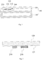
- Fig. 1 illustrates a partial schematic view of an electronic device according to an illustrative example of the present invention.
- the electronic device includes a body 100, a vibrator apparatus 200 and a controller, and the vibrator apparatus 200 is fixed in the body 100.
- the vibrator apparatus 200 may drive at least part of the body 100 to vibrate to generate sound, so as to replace a loudspeaker or other sound generators of the electronic device, which is conducive to cancelling a sound output hole of the electronic device and promoting the design of the full screen of the electronic device and the holeless electronic device.
- the body 100 includes a housing 110, and the vibrator apparatus 200 is fixed in the housing 110.
- the body 100 includes a housing 110 and a screen display 120 arranged on a front face of the housing 110, a space is formed between the housing 110 and the screen display 120, and the vibrator apparatus 200 is arranged in the space.
- a vibrator 210 of the vibrator apparatus 200 is bonded to a face of the housing 110 facing the screen display 120, and the vibrator apparatus 200 drives the housing 110 to vibrate to generate sound.
- the housing 110 may include a middle frame, and the vibrator apparatus 200 is fixed to the middle frame.
- the vibrator 210 of the vibrator apparatus 200 is bonded to a face of the screen display 120 facing the housing 110, and the vibrator apparatus 200 drives the screen display 120 to vibrate to generate sound. Further, when the vibrator 210 is bonded to the screen display 120, a gap may be formed between the vibrator apparatus 200 and the housing 110 to avoid driving the housing 110 to vibrate, thus ensuring the user's comfortable experience of holding the electronic device.
- Fig. 2 illustrates a partial schematic view of an electronic device according to an illustrative example of the present invention.
- the face of the display screen 120 facing the housing 110 is provided with a shielding layer 121, and the vibrator 210 of the vibrator apparatus 200 is bonded to a face of the shielding layer 121 facing away from the display screen 120.
- the vibrator 210 can be avoided from being directly bonded to the display screen 120 to produce a bonding mark, which otherwise affects the display effect of the display screen 120.
- the shielding layer 121 may be bonded to the display screen 120 through a solid adhesive, a liquid adhesive, a UV adhesive, a pressure-sensitive adhesive or the like with a relatively dark color.
- the vibrator apparatus 200 includes at least two vibrators 210 separately disposed in the body 100 and a flexible printed circuit board 220.
- Fig. 3 illustrates a partially enlarged schematic view of the electronic device in Fig. 1 .
- the at least two vibrators 210 are configured to vibrate to generate sound.
- the vibrator 210 includes a bonding face 213 configured be bonded to the display screen 120.
- Two or more than two vibrators 210 of the at least two vibrators 210 have at least one of different thicknesses, different areas of the bonding faces 213, or different shapes of the bonding faces 213.
- a thickness t of the vibrator 210 is a dimension of the vibrator 210 along a direction perpendicular to the bonding face 213.
- the thicknesses of the two or more than two vibrators 210 of the at least two vibrators 210 are different, or the areas of the bonding faces 213 of the two or more than two vibrators 210 of the at least two vibrators 210 are different, or the shapes of the bonding faces 213 of the two or more than two vibrators 210 of the at least two vibrators 210 are different, or both the thicknesses of the two or more than two vibrators 210 of the at least two vibrators 210 and the areas of the bonding faces 213 of the two or more than two vibrators 210 of the at least two vibrators 210 are different (for instance, the thickness and the area of bonding face 213 of one vibrator 210 are different from the thickness and the area of bonding face 213 of another vibrator 210), or both the thicknesses of the two or more than two vibrators 210 of the at least two vibrators 210 and the shapes of the bonding faces 213 of the two or more than two vibrators 210 of the at least two vibrators 210
- the two or more than two vibrators 210 of the at least two vibrators 210 have at least one of the different thicknesses, the different areas of the bonding faces 213 and the different shapes of the bonding faces 213, such that the vibrator apparatus 200 includes the vibrator 210 having the frequency response curve with an excellent low frequency performance, the vibrator 210 having the frequency response curve with an excellent intermediate frequency performance and the vibrator 210 having the frequency response curve with an excellent high frequency performance.
- the vibrationator apparatus 200 By means of the cooperation of these vibrators 210, not only the sound pressure level of the frequency response curve of the vibrator apparatus 200 is balanced and consistent, so as to improve the sound generation effect of the electronic device, but also more possibilities for flexible arrangements of the vibrator apparatus 200 are provided, which is conducive to reducing the occupied space, such that the electronic device is highly integrated and the volume of the electronic device is miniaturized. Moreover, compared with a plurality of identical vibrators 210, the thickness, the area of the bonding face 213, the shape of the bonding face 213 and/or the number of the vibrators 210 in the examples of the present invention can be flexibly designed, which is conducive to reducing the power consumption. The adoption of the vibrator apparatus 200 also facilitates the development of the full screen of the electronic device and the holeless electronic device.
- the at least two vibrators 210 include at least one of a piezoelectric film and a piezoelectric ceramic. In some examples, the at least two vibrators 210 are the piezoelectric films. In some examples, the at least two vibrators 210 are the piezoelectric ceramics. In some examples, the at least two vibrators 210 include the piezoelectric film and the piezoelectric ceramic. Further, the vibrator 210 may be other exciters, which are not specifically limited in the present invention. In some examples, the piezoelectric film is light in weight, soft, and can be easily applied to different spaces within the body 100. Compared with other exciters, the piezoelectric film and the piezoelectric ceramic are more conducive to saving the occupied space.
- a material of the vibrator 210 includes a piezoelectric material.
- the piezoelectric material includes lead zirconate titanate piezoelectric ceramics (PZT), and polyvinylidene fluoride (PVDF).
- the flexible printed circuit board (FPCB) 220 is connected with a face of the vibrator 210 which faces away from the bonding face 213.
- the FPCB 220 is also connected with a controller in the electronic device, and the controller controls the vibrator 210 to operate through the FPCB 220.
- the FPCB 220 may be fitted with spaces of different structures in the body 100, which is conducive to the high integration and the miniaturized volume of the electronic device.
- the vibrator apparatus 200 also includes an adhesive layer arranged on the bonding face 213, and the adhesive layer is configured to bond the bonding face 213 to the body 100.
- the way that the vibrator 210 is adhered to the body 100 through the adhesive layer is simple and facilitates the production and manufacture of the electronic device. Further, the vibrator 210 may also be fixed to the body 100 in other ways.
- the adhesive layer is formed by a solid adhesive, a liquid adhesive, a UV adhesive, or a pressure-sensitive adhesive.
- the controller is connected with the vibrator apparatus 200. Two or more than two vibrators 210 of the at least two vibrators 210 of the vibrator apparatus 200 are controlled to vibrate by the controller, and/or the controller controls the vibrator 210 of the vibrator apparatus 200 to vibrate under at least one driving voltage. In some examples, the controller may control a part of the vibrators 210 to vibrate and other vibrators 210 not to work, and may also control all the vibrators 210 to vibrate. The controller may control the vibrator 210 to vibrate under one driving voltage, and may also control the vibrator 210 to vibrate under a plurality of driving voltages.
- the controller includes an integrated circuit (IC), a plurality of vibrators 210 are connected to the IC in parallel, and the IC may control different vibrators 210 to vibrate with different driving voltages or with identical driving voltage.
- the plurality of vibrators 210 may also be connected to the IC in series.
- the controller includes a plurality of ICs, and the plurality of ICs are connected to a plurality of vibrators 210 in one to one correspondence. Each IC may control the vibrator 210 connected thereto with a determined driving voltage, and the driving voltages of the plurality of ICs may be identical or different.
- the vibrator 210 is connected to the IC through at least two metal conductive contacts.
- the controller is connected to the vibrator 210 through the flexible printed circuit board 220.
- Fig. 4 illustrates a schematic view of frequency response curves of three vibrators 210 having the different areas of the bonding faces 213 according to an illustrative example of the present invention.
- a horizontal axis (Freq) represents a frequency, and the frequency increases gradually along a direction to which an arrow of the horizontal axis points.
- a longitudinal axis (SPL) represents a sound pressure level, and the sound pressure level increases gradually along a direction to which an arrow of the longitudinal axis points.
- a frequency corresponding to a solid straight line is less than a frequency corresponding to a dotted straight line.
- Three frequency response curves A, B, C are the frequency response curves of Vibrator 1, Vibrator 2, and Vibrator 3, respectively.
- Vibrator 1, Vibrator 2, and Vibrator 3 have the same structure and thickness, but the area of the bonding face of Vibrator 1 >the area of the bonding face of Vibrator 2>the area of the bonding face of Vibrator 3. It can be known from Fig. 4 that, at the solid straight line (i.e. at a relatively low frequency), the sound pressure level of the frequency response curve A >the sound pressure level of the frequency response curve B>the sound pressure level of the frequency response curve C.
- the sound pressure level of the frequency response curve A decreases, the sound pressure level of the frequency response curve B and the sound pressure level of the frequency response curve C first decrease and then increase, and the increase amplitude of the sound pressure level of the frequency response curve C is relatively large.
- the sound pressure level of the frequency response curve A the sound pressure level of the frequency response curve B ⁇ the sound pressure level of the frequency response curve C.
- the larger the area of the bonding face 213 of the vibrator 210 is, the better the low frequency performance of the frequency response curve is, and the smaller the area of the bonding face 213 of the vibrator 210 is, the better the high frequency performance of the frequency response curve is.
- the at least two vibrators 210 include a first vibrator 211 and at least one second vibrator 212, and the first vibrator 211 and the at least one second vibrator 212 are dispersedly arranged.
- the area of the bonding face 213 of the first vibrator 211 is larger than that of the second vibrator 212.
- the low frequency performance of the frequency response curve of the first vibrator 211 is better than the low frequency performance of the frequency response curve of the second vibrator 211
- the high frequency performance of the frequency response curve of the second vibrator 212 is better than the high frequency performance of the frequency response curve of the first vibrator 211.
- the areas of the bonding faces 213 of all the second vibrators 212 are identical or different, which needs to be designed according to actual situations and is not specifically limited in the present invention.
- Fig. 5 illustrates a schematic view of frequency response curves of three vibrators 210 arranged at different positions according to an illustrative example of the present invention.
- a horizontal axis (Freq) represents a frequency, and the frequency increases gradually along a direction to which an arrow of the horizontal axis points.
- a longitudinal axis (SPL) represents a sound pressure level, and the sound pressure level increases gradually along a direction to which an arrow of the longitudinal axis points.
- a frequency corresponding to a solid straight line is less than a frequency corresponding to a dotted straight line.
- Three frequency response curves I, II, III are the frequency response curves of Vibrator 4, Vibrator 5, and Vibrator 6, respectively.
- Vibrator 4, Vibrator 5, and Vibrator 6 have the same structure and dimension, while the Vibrator 4 is arranged in middle of the body 100, Vibrator 5 is arranged at an edge of the body 100, and Vibrator 6 is arranged at a corner of the body 100.
- the sound pressure levels of the frequency response curves I, II, III first decrease and then increase.
- the dotted straight line i.e.
- the sound pressure level of the frequency response curve I the sound pressure level of the frequency response curve II ⁇ the sound pressure level of the frequency response curve III.
- the second vibrator 212 is arranged closer to the edge or the corner of the body 100 than the first vibrator 211.
- the low frequency performance of the frequency response curve of the first vibrator 211 is better than the low frequency performance of the frequency response curve of the second vibrator 212
- the high frequency performance of the frequency response curve of the second vibrator 212 is better than the high frequency performance of the frequency response curve of the first vibrator 211.
- the area of the bonding face 213 of the first vibrator 211 is larger than the area of the bonding face 213 of the second vibrator 212, such that the first vibrator 211 takes full advantages of its low frequency performance and the second vibrator 212 takes full advantages of its high frequency performance, which is conductive to that the vibrator apparatus 200 has the balanced and consistent frequency response curve.
- At least two second vibrators 212 are provided, and the at least two second vibrators 212 are arranged to be centered at a center of gravity of the first vibrator 211. In some examples, the at least two second vibrators 212 are arranged based on the center of gravity of the first vibrator 211, which is conductive to the effective cooperation between the first vibrator 211 and the second vibrator 212 so as to form the balanced and consistent frequency response curve.
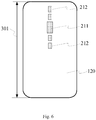
- Fig. 6 illustrates a schematic view of an arrangement of the vibrator apparatus 200 according to an illustrative example of the present invention.
- Fig. 7 illustrates a schematic view of an arrangement of the vibrator apparatus 200 according to an illustrative example of the present invention.
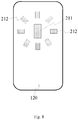
- Fig. 8 illustrates a schematic view of an arrangement of the vibrator apparatus 200 according to an illustrative example of the present invention.
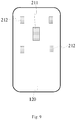
- Fig. 9 illustrates a schematic view of an arrangement of the vibrator apparatus 200 according to an illustrative example of the present invention.
- the present invention gives following examples for the arrangement of the vibrator apparatus 200 with reference to Figs. 6 to 9 .
- the at least two second vibrators 212 are arranged in one of a straight line form (as illustrated in Figs. 6 or 7 ), a circular form (as illustrated in Fig. 8 ), or a polygonal form (as illustrated in Fig. 9 ).
- the at least two second vibrators 212 may be arranged in one or more straight lines.
- the at least two second vibrators 212 are arranged on both sides of the first vibrator 211 in the straight line form along a length direction 301 of the body 100. In this way, the sound generated from the vibrator apparatus 200 has good directivity along the length direction 301, and thus a sound output hole in this direction can be replaced. Additionally, this arrangement is simple and is conductive to improving the production efficiency of the electronic device.
- the at least two second vibrators 212 are arranged on both sides of the first vibrator 211 in the straight line form along a width direction 302 of the body 100. In this way, the sound generated from the vibrator apparatus 200 has good directivity along the width direction 302, and thus a sound output hole in this direction can be replaced. Additionally, this arrangement is simple and is conductive to improving the production efficiency of the electronic device.
- a plurality of second vibrators 212 may be arranged around the first vibrator 211 in a form of a plurality of concentric circles.
- the plurality of second vibrators 212 may also be arranged around the first vibrator 211 in a form of a plurality of concentric polygons. Arrangement directions of the plurality of second vibrators 212 may be consistent, or may be staggered to form a structure similar to a flower.
- the at least two second vibrators 212 and the first vibrator 211 may also be arranged in other regular or irregular forms, which is not specifically limited in the present invention.
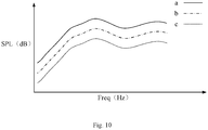
- Fig. 10 illustrates a schematic view of frequency response curves of three vibrators 210 with different thicknesses according to an illustrative example of the present invention.
- a horizontal axis (Freq) represents a frequency, and the frequency increases gradually along a direction to which an arrow of the horizontal axis points.
- a longitudinal axis (SPL) represents the sound pressure level, and the sound pressure level increases gradually along a direction to which an arrow of the longitudinal axis points.
- Three frequency response curves a, b, c are the frequency response curves of Vibrator 7, Vibrator 8, and Vibrator 9, respectively.
- Vibrator 7, Vibrator 8 and Vibrator 9 have the same structure and the same area of the bonding face 213, while the thickness of Vibrator 7>the thickness of Vibrator 8>the thickness of Vibrator 9.
- the sound pressure level of the frequency response curve a>the sound pressure level of the frequency response curve b>the sound pressure level of the frequency response curve c, and shapes of the frequency response curves a, b, c are identical.
- the larger the thickness of the vibrator 210 is, the larger the sound pressure level of the frequency response curve is, and the smaller the thickness of the vibrator 210 is, the smaller the sound pressure level of the frequency response curve is.
- the thickness of the first vibrator 211 is larger than the thickness of the second vibrator 212.
- the sound pressure level of the frequency response curve of the first vibrator 211 is improved.
- the cooperation between the first vibrator 211 and the second vibrator 212 makes the sound pressure level of the frequency response curve balanced and consistent, such that the electronic device has a good sound quality.
- the space at the edge or the corner of the body 100 is usually small, which is conductive to the cooperation between the first vibrator 211 and the second vibrator 212 to effectively occupy the space in the body 100.
- the thicknesses of the first vibrator 211 and the second vibrator 212 needs to be set according to the internal space of the body 100, the power consumption and the frequency response curve of the vibrator apparatus 200, which is not specifically limited in the present invention.
- the bonding face 213 of the vibrator 210 has a long strip shape. Compared with a square of the same area, the frequency response curve of the vibrator 210 whose bonding face 213 has the long strip shape has a better performance.
- the at least two vibrators 210 include the vibrator 210 with a single-layer structure and/or the vibrator 210 with a multi-layer structure.
- the at least two vibrators 210 including the vibrator 210 with the single-layer structure and/or the vibrator 210 with the multi-layer structure in conjunction with other factors such as the thickness, the area and the shape of the bonding face 213 or the like, it is further conductive to the balanced and consistent performance of the frequency response curve of the vibrator apparatus 200.
- At least one of the area and shape of the bonding face 213, the thickness, the position, the number, and the structure layer number of the vibrator 210 can be flexibly adjusted in conjunction with the internal space of the body 100 of the electronic device, such that the vibrator apparatus 200 satisfies requirements of the balanced and consistent frequency response curve, the small occupied space, and the little power consumption, or the like, thus achieving the purposes of being used flexibly, saving the space, and saving the power consumption, which is conductive to the high integration, the miniaturized volume, the full screen of the electronic device and the holeless electronic device.
Landscapes
- Physics & Mathematics (AREA)
- Acoustics & Sound (AREA)
- Engineering & Computer Science (AREA)
- Signal Processing (AREA)
- Health & Medical Sciences (AREA)
- Otolaryngology (AREA)
- General Health & Medical Sciences (AREA)
- Piezo-Electric Transducers For Audible Bands (AREA)
- Apparatuses For Generation Of Mechanical Vibrations (AREA)
Abstract
Description
- The present invention relates to a field of electronic devices, and more particularly to a vibrator apparatus and an electronic device including the vibrator apparatus.
- With the development of science and technology, a holeless electronic device with a full screen has become a mainstream of development, which needs to cancel a structure of a sound output hole arranged on the same face with a display screen, thus promoting the development of sound generation technology. Taking the sound generation technology by a screen as an example, a vibrator is fixed to the display screen and drives the display screen to vibrate to generate sound. In this way, a loudspeaker of the electronic device is replaced and the structure of the sound output hole is cancelled, which is conductive to the full screen of the electronic device and the holeless electronic device. However, a sound pressure level of a frequency response curve of the vibrator is not balanced at low and high frequencies, which is not conducive to ensuring a sound quality of the electronic device.
- The present invention provides an improved vibrator apparatus and an electronic device.
- A first aspect of the present invention provides a vibrator apparatus for an electronic device. The vibrator apparatus includes a plurality of vibrators, where the vibrator apparatus is fixed in a body of the electronic device, the plurality of vibrators are separately disposed in the body and configured to vibrate to generate sound. Each of the plurality of vibrators comprises a bonding face configured to be bonded to the body. Two or more vibrators of the plurality of vibrators have at least one of the following different qualities: thicknesses, different areas of the bonding face or different shapes of the bonding face. The thickness of each of the plurality of vibrators is measured along a direction perpendicular to the bonding face.
- Optionally, the plurality of vibrators include a first vibrator and at least one second vibrator, the first vibrator and the at least one second vibrator are separately disposed, and area of a bonding face of the first vibrator is larger than area of a bonding face of the second vibrator.
- Preferably, the at least one second vibrator is disposed closer to an edge or a corner of the body than the first vibrator is.
- Optionally, at least two second vibrators are provided, and the at least two second vibrators are disposed to be around a center of gravity of the first vibrator.
- Preferably, the at least two second vibrators are disposed in one of a straight line form, a circular form, or a polygonal form.
- Optionally, the at least two second vibrators are disposed on both sides of the first vibrator in the straight line form along a length direction of the body.
- Preferably, the at least two second vibrators are disposed on both sides of the first vibrator in the straight line form along a width direction of the body.
- Optionally, the thickness of the first vibrator is larger than the thickness of the second vibrator.
- Preferably, the plurality of vibrators include a vibrator with a single-layer structure and/or a vibrator with a multi-layer structure.
- Optionally, the plurality of vibrators include at least one of a piezoelectric film or a piezoelectric ceramic; and/or, the vibrator apparatus further includes an adhesive layer disposed on the bonding face, and the adhesive layer is configured to connect the bonding face to the body; and/or, the vibrator apparatus further includes a flexible printed circuit board, and the flexible printed circuit board is connected with the plurality of vibrators at a face opposite to the bonding face.
- A second aspect of the present invention provides an electronic device, and the electronic device includes a body and the vibrator apparatus according to any one of the above embodiments. The vibrator apparatus is fixed in the body.
- Optionally, the body includes a housing, a screen display disposed on a front face of the housing, and a space between the housing and the screen display, wherein the vibrator apparatus is mounted in the space.
- Preferably, the plurality of vibrators of the vibrator apparatus are bonded to a face of the screen display facing the housing, or the plurality of vibrators of the vibrator apparatus are bonded to a face of the housing facing the screen display.
- Optionally, a shielding layer is disposed on the face of the display screen facing the housing, and the plurality of vibrators are bonded to a face of the shielding layer facing away from the display screen.
- Preferably, the electronic device further includes a controller connected with the vibrator apparatus. The controller is configured to control vibration of two or more vibrators of the plurality of vibrators of the vibrator apparatus; and/or the controller is configured to control the plurality of vibrators of the vibrator apparatus to vibrate under at least one driving voltage.
- The vibrator apparatus and the electronic device provided by the embodiments of the present invention at least have following beneficial effects.
- In the vibrator apparatus and the electronic device according to the present invention, two or more than two vibrators of the plurality of vibrators have at least one of following different qualities: thicknesses, areas of the bonding face, or shapes of the bonding face. By means of the cooperation of these vibrators, not only the sound pressure level of the frequency response curve of the vibrator apparatus is balanced and consistent, so as to improve the sound generation effect, but also more possibilities for flexible arrangements of the vibrators are provided, which is conducive to reducing the occupied space, such that the electronic device is highly integrated and the volume of the electronic device is miniaturized. Moreover, compared with a plurality of identical vibrators, the thickness, the area of the bonding face, the shape of the bonding face and/or the number of the vibrators in the present invention can be flexibly designed, which is conducive to reducing the power consumption. The adoption of the vibrator apparatus also facilitates the development of the full screen of the electronic device and the holeless electronic device.
- It should be understood that the above general description and the detailed description below are merely used to explain the present invention, and cannot be construed as a limitation to the present invention.
- The accompanying drawings, which are incorporated in and constitute a part of this specification, illustrate examples consistent with the present invention and, together with the description, serve to explain the principles of the present invention.
-
Fig. 1 illustrates a schematic view of a partial structure of an electronic device according to an illustrative example of the present invention. -
Fig. 2 illustrates a schematic view of a partial structure of an electronic device according to an illustrative example of the present invention. -
Fig. 3 illustrates an enlarged schematic view of the partial structure of the electronic device inFig. 1 . -
Fig. 4 illustrates a schematic view of frequency response curves of three vibrators with different areas of bonding faces according to an illustrative example of the present invention. -
Fig. 5 illustrates a schematic view of frequency response curves of three vibrators arranged at different positions according to an illustrative example of the present invention. -
Fig. 6 illustrates a schematic view of an arrangement of a vibrator apparatus according to an illustrative example of the present invention. -
Fig. 7 illustrates a schematic view of an arrangement of a vibrator apparatus according to an illustrative example of the present invention. -
Fig. 8 illustrates a schematic view of an arrangement of a vibrator apparatus according to an illustrative example of the present invention. -
Fig. 9 illustrates a schematic view of an arrangement of a vibrator apparatus according to an illustrative example of the present invention. -
Fig. 10 illustrates a schematic view of frequency response curves of three vibrators with different thicknesses according to an illustrative example of the present invention. - Reference will now be made in detail to illustrative examples with the accompanying drawings. The following description refers to the accompanying drawings in which the same numbers in different drawings represent the same or similar elements unless otherwise represented. The implementations set forth in the following description of illustrative examples do not represent all implementations consistent with the present invention. Instead, they are merely examples of apparatuses and methods consistent with aspects related to the present invention as recited in the appended claims.
- The terms used in the present invention are merely for the purpose of describing specific examples, which are not intended to limit the present invention. Unless defined otherwise, the technical or scientific terminologies used in the present invention shall be the general meaning understood by those skilled in the related art of the present invention. Terms such as "first", "second" or the like used in the descriptions and claims of the present invention do not indicate any order, quantity or importance, but are only used to distinguish different components. Similarly, terms such as "one" or "a" do not refer to quantity limitation, but indicate the existence of at least one. Unless specified otherwise, terms such as "comprise", "include" or the like mean that the elements or objects presented before "comprise" or "include" contain the elements or objects and their equivalents presented after "comprise" or "include", while other elements or objects are not excluded. The terms "interconnect", "connected" or the like are not restricted to physical or mechanical connections, but may also be electrical connections, no matter direct or indirect.
- As used in the descriptions and the appended claims of the present invention, "a" and "the" in singular forms mean including plural forms, unless clearly indicated in the context otherwise. It should also be understood that, as used herein, the term "and/or" represents and contains any and all possible combinations of one or more associated listed items.
- In some examples, an electronic device includes a body and a vibrator arranged in the body, and the vibrator is configured to vibrate to generate sound. However, a frequency response curve of the vibrator does not have a balanced sound pressure level at low and high frequencies, which cannot ensure a sound quality and is not conducive to replacing a loudspeaker of the electronic device.
- In other examples, an electronic device includes a body and a vibrator apparatus arranged in the body. The vibrator apparatus includes a plurality of identical vibrators in a regular and orderly arrangement. Although the sound pressure level of the frequency response curve of the vibrator apparatus is relatively balanced, so as to solve a problem of the unbalanced sound pressure level in low, medium and high frequencies, the limitation is relatively great. The limitation includes that an arrangement of the plurality of vibrators is not flexible and occupies a large area, and the dimension and number of the plurality of vibrators cannot be designed flexibly, which is not conducive to reducing the power consumption.
- In order to solve the above problems, the present invention provides a vibrator apparatus and an electronic device, and the vibrator apparatus is fixed in a body of the electronic device. The vibrator apparatus includes at least two vibrators separately disposed in the body, and configured vibrate to generate sound. The vibrator includes a bonding face configured to be bonded to the body. Two or more than two vibrators of the at least two vibrators have at least one of different thicknesses, different areas of the bonding faces and different shapes of the bonding faces. The thickness of the vibrator is a dimension of the vibrator along a direction perpendicular to the bonding face. The electronic device includes the body and the vibrator apparatus fixed in the body.
- In the vibrator apparatus and the electronic device according to the present invention, the two or more than two vibrators of the at least two vibrators have at least one of following different qualities: thicknesses, areas of the bonding face, or shapes of the bonding face. By means of the cooperation of these vibrators, not only the sound pressure level of the frequency response curve of the vibrator apparatus is balanced and consistent, so as to improve the sound generation effect, but also more possibilities for flexible arrangements of the vibrators are provided, which is conducive to reducing the occupied space, such that the electronic device is highly integrated and the volume of the electronic device is miniaturized. Moreover, compared with a plurality of identical vibrators, the thickness, the area of the bonding face, the shape of the bonding face and/or the number of the vibrators in the examples of the present invention can be flexibly designed, which is conducive to reducing the power consumption. The adoption of the vibrator apparatus also facilitates the development of the full screen of the electronic device and the holeless electronic device.
- In order to understand the vibrator apparatus and the electronic device provided in the present invention more clearly, following detailed descriptions are made with reference to
Figs. 1-10 . - The electronic device provided in the examples of the present invention includes, but is not limited to, a mobile phone, a tablet computer, an iPad, a digital broadcasting terminal, a message receiving and sending device, a game console, a medical facility, a fitness facility, a personal digital assistant, and other intelligent devices, etc.
-
Fig. 1 illustrates a partial schematic view of an electronic device according to an illustrative example of the present invention. The electronic device includes abody 100, avibrator apparatus 200 and a controller, and thevibrator apparatus 200 is fixed in thebody 100. Thevibrator apparatus 200 may drive at least part of thebody 100 to vibrate to generate sound, so as to replace a loudspeaker or other sound generators of the electronic device, which is conducive to cancelling a sound output hole of the electronic device and promoting the design of the full screen of the electronic device and the holeless electronic device. - In some examples, the
body 100 includes ahousing 110, and thevibrator apparatus 200 is fixed in thehousing 110. - In other examples, as illustrated in
Fig. 1 , thebody 100 includes ahousing 110 and ascreen display 120 arranged on a front face of thehousing 110, a space is formed between thehousing 110 and thescreen display 120, and thevibrator apparatus 200 is arranged in the space. In some examples, avibrator 210 of thevibrator apparatus 200 is bonded to a face of thehousing 110 facing thescreen display 120, and thevibrator apparatus 200 drives thehousing 110 to vibrate to generate sound. Thehousing 110 may include a middle frame, and thevibrator apparatus 200 is fixed to the middle frame. - In other examples, the
vibrator 210 of thevibrator apparatus 200 is bonded to a face of thescreen display 120 facing thehousing 110, and thevibrator apparatus 200 drives thescreen display 120 to vibrate to generate sound. Further, when thevibrator 210 is bonded to thescreen display 120, a gap may be formed between thevibrator apparatus 200 and thehousing 110 to avoid driving thehousing 110 to vibrate, thus ensuring the user's comfortable experience of holding the electronic device. -
Fig. 2 illustrates a partial schematic view of an electronic device according to an illustrative example of the present invention. In some examples, as illustrated inFig. 2 , the face of thedisplay screen 120 facing thehousing 110 is provided with ashielding layer 121, and thevibrator 210 of thevibrator apparatus 200 is bonded to a face of theshielding layer 121 facing away from thedisplay screen 120. In this way, thevibrator 210 can be avoided from being directly bonded to thedisplay screen 120 to produce a bonding mark, which otherwise affects the display effect of thedisplay screen 120. In some examples, theshielding layer 121 may be bonded to thedisplay screen 120 through a solid adhesive, a liquid adhesive, a UV adhesive, a pressure-sensitive adhesive or the like with a relatively dark color. - The
vibrator apparatus 200 includes at least twovibrators 210 separately disposed in thebody 100 and a flexible printedcircuit board 220. -
Fig. 3 illustrates a partially enlarged schematic view of the electronic device inFig. 1 . The at least twovibrators 210 are configured to vibrate to generate sound. As illustrated inFig. 3 , thevibrator 210 includes abonding face 213 configured be bonded to thedisplay screen 120. Two or more than twovibrators 210 of the at least twovibrators 210 have at least one of different thicknesses, different areas of the bonding faces 213, or different shapes of the bonding faces 213. A thickness t of thevibrator 210 is a dimension of thevibrator 210 along a direction perpendicular to thebonding face 213. - It should be noted that, the thicknesses of the two or more than two vibrators 210 of the at least two vibrators 210 are different, or the areas of the bonding faces 213 of the two or more than two vibrators 210 of the at least two vibrators 210 are different, or the shapes of the bonding faces 213 of the two or more than two vibrators 210 of the at least two vibrators 210 are different, or both the thicknesses of the two or more than two vibrators 210 of the at least two vibrators 210 and the areas of the bonding faces 213 of the two or more than two vibrators 210 of the at least two vibrators 210 are different (for instance, the thickness and the area of bonding face 213 of one vibrator 210 are different from the thickness and the area of bonding face 213 of another vibrator 210), or both the thicknesses of the two or more than two vibrators 210 of the at least two vibrators 210 and the shapes of the bonding faces 213 of the two or more than two vibrators 210 of the at least two vibrators 210 are different (for instance, the thickness and the shape of the bonding face 213 of one vibrator 210 are different from the thickness and the shape of the bonding face 213 of another vibrator 210), or both the areas of the bonding faces 213 of the two or more than two vibrators 210 of the at least two vibrators 210 and the shapes of the bonding faces 213 of the two or more than two vibrators 210 of the at least two vibrators 210 are different (for instance, the area and the shape of the bonding face 213 of one vibrator 210 are different from the area and the shape of the bonding face 213 of another vibrator 210), or the thicknesses, the areas of the bonding faces 213 and the shapes of the bonding faces 213 of the two or more than two vibrators 210 of the at least two vibrators 210 are different. Further, some
vibrators 210 of the at least twovibrators 210 may have identical thicknesses, identical areas of the bonding faces 213, and/or identical shapes of the bonding faces 213. - In the
vibrator apparatus 200 and the electronic device according to the example of the present invention, the two or more than twovibrators 210 of the at least twovibrators 210 have at least one of the different thicknesses, the different areas of the bonding faces 213 and the different shapes of the bonding faces 213, such that thevibrator apparatus 200 includes thevibrator 210 having the frequency response curve with an excellent low frequency performance, thevibrator 210 having the frequency response curve with an excellent intermediate frequency performance and thevibrator 210 having the frequency response curve with an excellent high frequency performance. By means of the cooperation of thesevibrators 210, not only the sound pressure level of the frequency response curve of thevibrator apparatus 200 is balanced and consistent, so as to improve the sound generation effect of the electronic device, but also more possibilities for flexible arrangements of thevibrator apparatus 200 are provided, which is conducive to reducing the occupied space, such that the electronic device is highly integrated and the volume of the electronic device is miniaturized. Moreover, compared with a plurality ofidentical vibrators 210, the thickness, the area of thebonding face 213, the shape of thebonding face 213 and/or the number of thevibrators 210 in the examples of the present invention can be flexibly designed, which is conducive to reducing the power consumption. The adoption of thevibrator apparatus 200 also facilitates the development of the full screen of the electronic device and the holeless electronic device. - In some examples, the at least two
vibrators 210 include at least one of a piezoelectric film and a piezoelectric ceramic. In some examples, the at least twovibrators 210 are the piezoelectric films. In some examples, the at least twovibrators 210 are the piezoelectric ceramics. In some examples, the at least twovibrators 210 include the piezoelectric film and the piezoelectric ceramic. Further, thevibrator 210 may be other exciters, which are not specifically limited in the present invention. In some examples, the piezoelectric film is light in weight, soft, and can be easily applied to different spaces within thebody 100. Compared with other exciters, the piezoelectric film and the piezoelectric ceramic are more conducive to saving the occupied space. - In some examples, a material of the
vibrator 210 includes a piezoelectric material. In some examples, the piezoelectric material includes lead zirconate titanate piezoelectric ceramics (PZT), and polyvinylidene fluoride (PVDF). - The flexible printed circuit board (FPCB) 220 is connected with a face of the
vibrator 210 which faces away from thebonding face 213. In some examples, theFPCB 220 is also connected with a controller in the electronic device, and the controller controls thevibrator 210 to operate through theFPCB 220. Moreover, theFPCB 220 may be fitted with spaces of different structures in thebody 100, which is conducive to the high integration and the miniaturized volume of the electronic device. - In some examples, the
vibrator apparatus 200 also includes an adhesive layer arranged on thebonding face 213, and the adhesive layer is configured to bond thebonding face 213 to thebody 100. In some examples, the way that thevibrator 210 is adhered to thebody 100 through the adhesive layer is simple and facilitates the production and manufacture of the electronic device. Further, thevibrator 210 may also be fixed to thebody 100 in other ways. In some examples, the adhesive layer is formed by a solid adhesive, a liquid adhesive, a UV adhesive, or a pressure-sensitive adhesive. - The controller is connected with the
vibrator apparatus 200. Two or more than twovibrators 210 of the at least twovibrators 210 of thevibrator apparatus 200 are controlled to vibrate by the controller, and/or the controller controls thevibrator 210 of thevibrator apparatus 200 to vibrate under at least one driving voltage. In some examples, the controller may control a part of thevibrators 210 to vibrate andother vibrators 210 not to work, and may also control all thevibrators 210 to vibrate. The controller may control thevibrator 210 to vibrate under one driving voltage, and may also control thevibrator 210 to vibrate under a plurality of driving voltages. In this way, it is flexible to control a part of thevibrators 210 to vibrate and adjust the driving voltage based on actual situations, which is not only conductive to the balanced and consistent performance of the frequency response curve of thevibrator apparatus 200, but also conducive to energy saving and consumption reduction. - In some examples, the controller includes an integrated circuit (IC), a plurality of
vibrators 210 are connected to the IC in parallel, and the IC may controldifferent vibrators 210 to vibrate with different driving voltages or with identical driving voltage. The plurality ofvibrators 210 may also be connected to the IC in series. In other examples, the controller includes a plurality of ICs, and the plurality of ICs are connected to a plurality ofvibrators 210 in one to one correspondence. Each IC may control thevibrator 210 connected thereto with a determined driving voltage, and the driving voltages of the plurality of ICs may be identical or different. - In some examples, the
vibrator 210 is connected to the IC through at least two metal conductive contacts. When thevibrator apparatus 200 includes the flexible printedcircuit board 220, the controller is connected to thevibrator 210 through the flexible printedcircuit board 220. - The influences of the area of the
bonding face 213, the thickness and the position of thevibrator 210 on the frequency response curve are respectively explained as follows with reference to the drawings. -
Fig. 4 illustrates a schematic view of frequency response curves of threevibrators 210 having the different areas of the bonding faces 213 according to an illustrative example of the present invention. InFig. 4 , a horizontal axis (Freq) represents a frequency, and the frequency increases gradually along a direction to which an arrow of the horizontal axis points. A longitudinal axis (SPL) represents a sound pressure level, and the sound pressure level increases gradually along a direction to which an arrow of the longitudinal axis points. A frequency corresponding to a solid straight line is less than a frequency corresponding to a dotted straight line. Three frequency response curves A, B, C are the frequency response curves ofVibrator 1, Vibrator 2, andVibrator 3, respectively.Vibrator 1, Vibrator 2, andVibrator 3 have the same structure and thickness, but the area of the bonding face ofVibrator 1 >the area of the bonding face of Vibrator 2>the area of the bonding face ofVibrator 3. It can be known fromFig. 4 that, at the solid straight line (i.e. at a relatively low frequency), the sound pressure level of the frequency response curve A >the sound pressure level of the frequency response curve B>the sound pressure level of the frequency response curve C. With the increase of the frequency, the sound pressure level of the frequency response curve A decreases, the sound pressure level of the frequency response curve B and the sound pressure level of the frequency response curve C first decrease and then increase, and the increase amplitude of the sound pressure level of the frequency response curve C is relatively large. At the dotted straight line (i.e. at a relatively high frequency), the sound pressure level of the frequency response curve A<the sound pressure level of the frequency response curve B<the sound pressure level of the frequency response curve C. As can be seen, the larger the area of thebonding face 213 of thevibrator 210 is, the better the low frequency performance of the frequency response curve is, and the smaller the area of thebonding face 213 of thevibrator 210 is, the better the high frequency performance of the frequency response curve is. - In some examples, the at least two
vibrators 210 include afirst vibrator 211 and at least onesecond vibrator 212, and thefirst vibrator 211 and the at least onesecond vibrator 212 are dispersedly arranged. The area of thebonding face 213 of thefirst vibrator 211 is larger than that of thesecond vibrator 212. In some examples, according to the influence of the area of thebonding face 213 on the frequency response curve, the low frequency performance of the frequency response curve of thefirst vibrator 211 is better than the low frequency performance of the frequency response curve of thesecond vibrator 211, and the high frequency performance of the frequency response curve of thesecond vibrator 212 is better than the high frequency performance of the frequency response curve of thefirst vibrator 211. By means of the cooperation of thefirst vibrator 211 and thesecond vibrator 212, it is conductive to the balanced and consistent sound pressure level of the frequency response curve of thevibrator apparatus 200. - In addition, in the example of the present invention, the areas of the bonding faces 213 of all the
second vibrators 212 are identical or different, which needs to be designed according to actual situations and is not specifically limited in the present invention. -
Fig. 5 illustrates a schematic view of frequency response curves of threevibrators 210 arranged at different positions according to an illustrative example of the present invention. InFig. 5 , a horizontal axis (Freq) represents a frequency, and the frequency increases gradually along a direction to which an arrow of the horizontal axis points. A longitudinal axis (SPL) represents a sound pressure level, and the sound pressure level increases gradually along a direction to which an arrow of the longitudinal axis points. A frequency corresponding to a solid straight line is less than a frequency corresponding to a dotted straight line. Three frequency response curves I, II, III are the frequency response curves of Vibrator 4, Vibrator 5, and Vibrator 6, respectively. Vibrator 4, Vibrator 5, and Vibrator 6 have the same structure and dimension, while the Vibrator 4 is arranged in middle of thebody 100, Vibrator 5 is arranged at an edge of thebody 100, and Vibrator 6 is arranged at a corner of thebody 100. As illustrated inFig. 5 , at the solid straight line (i.e. at a relatively low frequency), the sound pressure level of the frequency response curve I>the sound pressure level of the frequency response curve II>the sound pressure level of the frequency response curve III. With the increase of the frequency, the sound pressure levels of the frequency response curves I, II, III first decrease and then increase. At the dotted straight line (i.e. at a relatively high frequency), the sound pressure level of the frequency response curve I<the sound pressure level of the frequency response curve II<the sound pressure level of the frequency response curve III. As can be seen, the closer thevibrator 210 is to the middle of thebody 100, the better the low frequency performance of the frequency response curve is, and the closer thevibrator 210 is to the edge or the corner of thebody 100, the better the high frequency performance of the frequency response curve is. - In some examples, the
second vibrator 212 is arranged closer to the edge or the corner of thebody 100 than thefirst vibrator 211. In some examples, according to the influence of the arrangement position of thevibrator 210 on the frequency response curve, the low frequency performance of the frequency response curve of thefirst vibrator 211 is better than the low frequency performance of the frequency response curve of thesecond vibrator 212, and the high frequency performance of the frequency response curve of thesecond vibrator 212 is better than the high frequency performance of the frequency response curve of thefirst vibrator 211. Moreover, the area of thebonding face 213 of thefirst vibrator 211 is larger than the area of thebonding face 213 of thesecond vibrator 212, such that thefirst vibrator 211 takes full advantages of its low frequency performance and thesecond vibrator 212 takes full advantages of its high frequency performance, which is conductive to that thevibrator apparatus 200 has the balanced and consistent frequency response curve. - In some examples, at least two
second vibrators 212 are provided, and the at least twosecond vibrators 212 are arranged to be centered at a center of gravity of thefirst vibrator 211. In some examples, the at least twosecond vibrators 212 are arranged based on the center of gravity of thefirst vibrator 211, which is conductive to the effective cooperation between thefirst vibrator 211 and thesecond vibrator 212 so as to form the balanced and consistent frequency response curve. -
Fig. 6 illustrates a schematic view of an arrangement of thevibrator apparatus 200 according to an illustrative example of the present invention.Fig. 7 illustrates a schematic view of an arrangement of thevibrator apparatus 200 according to an illustrative example of the present invention.Fig. 8 illustrates a schematic view of an arrangement of thevibrator apparatus 200 according to an illustrative example of the present invention.Fig. 9 illustrates a schematic view of an arrangement of thevibrator apparatus 200 according to an illustrative example of the present invention. The present invention gives following examples for the arrangement of thevibrator apparatus 200 with reference toFigs. 6 to 9 . - In some examples, the at least two
second vibrators 212 are arranged in one of a straight line form (as illustrated inFigs. 6 or7 ), a circular form (as illustrated inFig. 8 ), or a polygonal form (as illustrated inFig. 9 ). - Based on the requirements for the frequency response curve, the occupied space and the power consumption of the
vibrator apparatus 200, the at least twosecond vibrators 212 may be arranged in one or more straight lines. In some examples, as illustrated inFig. 6 , the at least twosecond vibrators 212 are arranged on both sides of thefirst vibrator 211 in the straight line form along alength direction 301 of thebody 100. In this way, the sound generated from thevibrator apparatus 200 has good directivity along thelength direction 301, and thus a sound output hole in this direction can be replaced. Additionally, this arrangement is simple and is conductive to improving the production efficiency of the electronic device. - In other examples, as illustrated in
Fig. 7 , the at least twosecond vibrators 212 are arranged on both sides of thefirst vibrator 211 in the straight line form along awidth direction 302 of thebody 100. In this way, the sound generated from thevibrator apparatus 200 has good directivity along thewidth direction 302, and thus a sound output hole in this direction can be replaced. Additionally, this arrangement is simple and is conductive to improving the production efficiency of the electronic device. - In addition, a plurality of
second vibrators 212 may be arranged around thefirst vibrator 211 in a form of a plurality of concentric circles. The plurality ofsecond vibrators 212 may also be arranged around thefirst vibrator 211 in a form of a plurality of concentric polygons. Arrangement directions of the plurality ofsecond vibrators 212 may be consistent, or may be staggered to form a structure similar to a flower. - In addition, the at least two
second vibrators 212 and thefirst vibrator 211 may also be arranged in other regular or irregular forms, which is not specifically limited in the present invention. -
Fig. 10 illustrates a schematic view of frequency response curves of threevibrators 210 with different thicknesses according to an illustrative example of the present invention. InFig. 10 , a horizontal axis (Freq) represents a frequency, and the frequency increases gradually along a direction to which an arrow of the horizontal axis points. A longitudinal axis (SPL) represents the sound pressure level, and the sound pressure level increases gradually along a direction to which an arrow of the longitudinal axis points. Three frequency response curves a, b, c are the frequency response curves of Vibrator 7,Vibrator 8, and Vibrator 9, respectively. Vibrator 7,Vibrator 8 and Vibrator 9 have the same structure and the same area of thebonding face 213, while the thickness of Vibrator 7>the thickness ofVibrator 8>the thickness of Vibrator 9. It can be seen fromFig. 10 that, the sound pressure level of the frequency response curve a>the sound pressure level of the frequency response curve b>the sound pressure level of the frequency response curve c, and shapes of the frequency response curves a, b, c are identical. As can be seen, the larger the thickness of thevibrator 210 is, the larger the sound pressure level of the frequency response curve is, and the smaller the thickness of thevibrator 210 is, the smaller the sound pressure level of the frequency response curve is. - In some examples, the thickness of the
first vibrator 211 is larger than the thickness of thesecond vibrator 212. In some examples, according to the influence of the thickness on the frequency response curve, by configuring the thickness of thefirst vibrator 211 to be larger than the thickness of thesecond vibrator 212, the sound pressure level of the frequency response curve of thefirst vibrator 211 is improved. The cooperation between thefirst vibrator 211 and thesecond vibrator 212 makes the sound pressure level of the frequency response curve balanced and consistent, such that the electronic device has a good sound quality. Moreover, the space at the edge or the corner of thebody 100 is usually small, which is conductive to the cooperation between thefirst vibrator 211 and thesecond vibrator 212 to effectively occupy the space in thebody 100. The thicknesses of thefirst vibrator 211 and thesecond vibrator 212 needs to be set according to the internal space of thebody 100, the power consumption and the frequency response curve of thevibrator apparatus 200, which is not specifically limited in the present invention. - In some examples, the
bonding face 213 of thevibrator 210 has a long strip shape. Compared with a square of the same area, the frequency response curve of thevibrator 210 whosebonding face 213 has the long strip shape has a better performance. - In some examples, further as illustrated in
Fig. 2 , the at least twovibrators 210 include thevibrator 210 with a single-layer structure and/or thevibrator 210 with a multi-layer structure. In some examples, for thevibrators 210 with the same thickness, the more the layers of thevibrator 210 are, the better the performance of the frequency response curve of thevibrator 210 is. By means of the at least twovibrators 210 including thevibrator 210 with the single-layer structure and/or thevibrator 210 with the multi-layer structure, in conjunction with other factors such as the thickness, the area and the shape of thebonding face 213 or the like, it is further conductive to the balanced and consistent performance of the frequency response curve of thevibrator apparatus 200. - In some examples, the smaller the volume of the
vibrator 210 is, the less the power consumption of thevibrator 210 is. That is, the smaller the area of thebonding face 213 and/or the thickness is, the less the power consumption of thevibrator 210 is. Since the at least twovibrators 210 have at least one of the different thicknesses and the different areas of the bonding faces 213, the volumes of the at least twovibrators 210 are different, which provides more possibilities for flexible arrangements. Compared with a plurality ofidentical vibrators 210, thevibrator apparatus 200 provided in the present invention can flexibly adjust the thickness of thevibrator 210, the area of thebonding face 213 and the number of thevibrators 210, which is conducive to reducing the power consumption. - To sum up, when the
vibrator apparatus 200 is applied, at least one of the area and shape of thebonding face 213, the thickness, the position, the number, and the structure layer number of thevibrator 210 can be flexibly adjusted in conjunction with the internal space of thebody 100 of the electronic device, such that thevibrator apparatus 200 satisfies requirements of the balanced and consistent frequency response curve, the small occupied space, and the little power consumption, or the like, thus achieving the purposes of being used flexibly, saving the space, and saving the power consumption, which is conductive to the high integration, the miniaturized volume, the full screen of the electronic device and the holeless electronic device. - The above examples of the present invention may be complementary for each other under the case of no conflict.
- The above description is only a preferable example of the present invention, which is not construed to limit the present invention. Any modification, equivalent replacement, improvement made within the spirit and principle of the present invention should be included in the protection scope of the present invention.
Claims (15)
- A vibrator apparatus (200) for an electronic device, comprising:a plurality of vibrators (210), wherein the vibrator apparatus (200) is fixed in a body (100) of the electronic device, the plurality of vibrators (210) are separately disposed in the body (100) and configured to vibrate to generate sound, and each of the plurality of vibrators (210) comprises a bonding face (213) configured to be bonded to the body (100),wherein two or more vibrators of the plurality of vibrators (210) have at least one of following different qualities: thicknesses, areas of the bonding face (213), or shapes of the bonding face (213), andwherein thickness of each of the plurality of vibrators (210) is measured along a direction perpendicular to the bonding face (213).
- The vibrator apparatus (200) according to claim 1, wherein the plurality of vibrators (210) comprise a first vibrator (211) and at least one second vibrator (212), the first vibrator (211) and the at least one second vibrator (212) are separately disposed, and area of a bonding face (213) of the first vibrator (211) is larger than area of a bonding face (213) of the second vibrator (212).
- The vibrator apparatus (200) according to claim 2, wherein the at least one second vibrator (212) is disposed closer to an edge or a corner of the body (100) than the first vibrator (211) is.
- The vibrator apparatus (200) according to claim 2 or 3, wherein at least two second vibrators (212) are provided, and the at least two second vibrators (212) are disposed to be around a center of gravity of the first vibrator (211).
- The vibrator apparatus (200) according to any one of claims 2 to 4, wherein the at least two second vibrators (212) are disposed in one of a straight line form, a circular form, or a polygonal form.
- The vibrator apparatus (200) according to claim 5, wherein the at least two second vibrators (212) are disposed on both sides of the first vibrator (211) in the straight line form along a length direction (301) of the body (100).
- The vibrator apparatus (200) according to claim 5, wherein the at least two second vibrators (212) are disposed on both sides of the first vibrator (211) in the straight line form along a width direction (302) of the body (100).
- The vibrator apparatus (200) according to any one of claims 2-7, wherein thickness of the first vibrator (211) is larger than thickness of the second vibrator (212).
- The vibrator apparatus (200) according to any one of claims 1-8, wherein the plurality of vibrators (210) comprise a vibrator with a single-layer structure and/or a vibrator with a multi-layer structure.
- The vibrator apparatus (200) according to any one of claims 1-9, wherein the plurality of vibrators (210) comprise at least one of a piezoelectric film or a piezoelectric ceramic; and/or,
the vibrator apparatus (200) further comprises an adhesive layer disposed on the bonding face (213), and the adhesive layer is configured to connect the bonding face (213) to the body (100); and/or,
the vibrator apparatus (200) further comprises a flexible printed circuit board (220), and the flexible printed circuit board (220) is connected with the plurality of vibrators (210) at a face opposite to the bonding face (213). - An electronic device, comprising:a body (100); anda vibrator apparatus (200) according to any one of claims 1-10, the vibrator apparatus (200) being fixed in the body (100).
- The electronic device according to claim 11, wherein the body (100) comprises a housing (110), a screen display (120) disposed on a front face of the housing (110), and a space between the housing (110) and the screen display (120), wherein the vibrator apparatus (200) is mounted in the space.
- The electronic device according to claim 12, wherein the plurality of vibrators (210) of the vibrator apparatus (200) are bonded to a face of the screen display (120) facing the housing (110), or the plurality of vibrators (210) of the vibrator apparatus (200) are bonded to a face of the housing (110) facing the screen display (120).
- The electronic device according to claim 12 or 13, wherein a shielding layer (121) is disposed on the face of the display screen facing the housing (110), and the plurality of vibrators (210) are bonded to a face of the shielding layer (121) facing away from the display screen.
- The electronic device according to any one of claims 11-14, further comprising a controller connected with the vibrator apparatus (200),
wherein the controller is configured to control vibration of two or more vibrators of the plurality of vibrators (210) of the vibrator apparatus (200); and/or
the controller is configured to control the plurality of vibrators (210) of the vibrator apparatus (200) to vibrate under at least one driving voltage.
Applications Claiming Priority (1)
| Application Number | Priority Date | Filing Date | Title |
|---|---|---|---|
| CN202010125988.XA CN113316060A (en) | 2020-02-27 | 2020-02-27 | Vibrator module and electronic equipment |
Publications (2)
| Publication Number | Publication Date |
|---|---|
| EP3873106A1 true EP3873106A1 (en) | 2021-09-01 |
| EP3873106B1 EP3873106B1 (en) | 2025-03-19 |
Family
ID=71846218
Family Applications (1)
| Application Number | Title | Priority Date | Filing Date |
|---|---|---|---|
| EP20188271.9A Active EP3873106B1 (en) | 2020-02-27 | 2020-07-29 | Vibrator apparatus and electronic device having the same |
Country Status (3)
| Country | Link |
|---|---|
| US (1) | US11064286B1 (en) |
| EP (1) | EP3873106B1 (en) |
| CN (1) | CN113316060A (en) |
Families Citing this family (1)
| Publication number | Priority date | Publication date | Assignee | Title |
|---|---|---|---|---|
| KR102722549B1 (en) * | 2020-10-16 | 2024-10-25 | 엘지디스플레이 주식회사 | Display device |
Citations (2)
| Publication number | Priority date | Publication date | Assignee | Title |
|---|---|---|---|---|
| US20120140969A1 (en) * | 2010-12-02 | 2012-06-07 | Akiko Fujise | Piezoelectric speaker and piezoelectric speaker array |
| US20190297420A1 (en) * | 2017-02-24 | 2019-09-26 | Nvf Tech Ltd | Panel loudspeaker controller and a panel loudspeaker |
Family Cites Families (8)
| Publication number | Priority date | Publication date | Assignee | Title |
|---|---|---|---|---|
| JP5489842B2 (en) * | 2010-04-26 | 2014-05-14 | オリンパスイメージング株式会社 | Vibrating device and imaging device using the same |
| JP5534448B2 (en) * | 2010-09-29 | 2014-07-02 | エスアイアイ・クリスタルテクノロジー株式会社 | Piezoelectric vibrator, piezoelectric vibrator, oscillator, electronic device and radio clock |
| US8934228B2 (en) * | 2011-03-21 | 2015-01-13 | Apple Inc. | Display-based speaker structures for electronic devices |
| WO2014024736A1 (en) * | 2012-08-10 | 2014-02-13 | 京セラ株式会社 | Sound generator, sound generation device, and electronic device |
| US9525932B2 (en) * | 2015-01-26 | 2016-12-20 | Bose Corporation | Acoustic device having active drivers mounted to a passive radiator diaphragm |
| KR102420554B1 (en) * | 2017-08-10 | 2022-07-14 | 삼성디스플레이 주식회사 | Display panel, bracket and display device comprising the same |
| KR102494625B1 (en) * | 2017-08-28 | 2023-02-01 | 삼성디스플레이 주식회사 | Display device |
| CN108881523B (en) * | 2018-04-28 | 2020-10-16 | 歌尔股份有限公司 | Electronic display device and electronic device |
-
2020
- 2020-02-27 CN CN202010125988.XA patent/CN113316060A/en active Pending
- 2020-07-16 US US16/931,190 patent/US11064286B1/en active Active
- 2020-07-29 EP EP20188271.9A patent/EP3873106B1/en active Active
Patent Citations (2)
| Publication number | Priority date | Publication date | Assignee | Title |
|---|---|---|---|---|
| US20120140969A1 (en) * | 2010-12-02 | 2012-06-07 | Akiko Fujise | Piezoelectric speaker and piezoelectric speaker array |
| US20190297420A1 (en) * | 2017-02-24 | 2019-09-26 | Nvf Tech Ltd | Panel loudspeaker controller and a panel loudspeaker |
Also Published As
| Publication number | Publication date |
|---|---|
| US11064286B1 (en) | 2021-07-13 |
| EP3873106B1 (en) | 2025-03-19 |
| CN113316060A (en) | 2021-08-27 |
Similar Documents
| Publication | Publication Date | Title |
|---|---|---|
| KR102434276B1 (en) | Display apparatus | |
| US9813823B2 (en) | Piezoelectric element, and piezoelectric vibrating apparatus, portable terminal, sound generator, sound generating apparatus, and electronic device comprising the piezoelectric element | |
| TWI545967B (en) | Sound generator, sound generating device and electronic machine | |
| JP7656664B2 (en) | Display and vibration device | |
| JP2021141584A (en) | Display apparatus | |
| EP4020945B1 (en) | Display terminal | |
| CN104054356B (en) | Sound generator, sound generation device and electronic equipment | |
| US11064286B1 (en) | Vibrator apparatus and electronic device having the same | |
| CN104335602B (en) | Sound generator, sound generating device and electronic equipment | |
| CN103260116B (en) | Flat woofer | |
| JP2011244379A (en) | Piezoelectric sounder | |
| JP7637107B2 (en) | Sound equipment | |
| KR20240079674A (en) | Apparatus | |
| CN118283509A (en) | Equipment for sound | |
| KR20240003119A (en) | Apparatus | |
| CN117336650A (en) | Electronic equipment | |
| WO2016017475A1 (en) | Piezoelectric element, acoustic generator, acoustic generation device, and electronic apparatus | |
| US20250175743A1 (en) | Acoustic apparatus | |
| CN116405845B (en) | Sound apparatus and vehicle apparatus | |
| CN210518433U (en) | Electronic device | |
| KR20250132871A (en) | Apparatus | |
| KR20250127663A (en) | Apparatus | |
| KR20250037346A (en) | Apparatus | |
| JP2017118424A (en) | SOUND GENERATOR, SOUND GENERATOR, AND ELECTRONIC DEVICE | |
| KR20190122090A (en) | Piezoelectric device, piezoelectric actuator including the device, and piezoelectric module including the actuator |
Legal Events
| Date | Code | Title | Description |
|---|---|---|---|
| PUAI | Public reference made under article 153(3) epc to a published international application that has entered the european phase |
Free format text: ORIGINAL CODE: 0009012 |
|
| STAA | Information on the status of an ep patent application or granted ep patent |
Free format text: STATUS: THE APPLICATION HAS BEEN PUBLISHED |
|
| AK | Designated contracting states |
Kind code of ref document: A1 Designated state(s): AL AT BE BG CH CY CZ DE DK EE ES FI FR GB GR HR HU IE IS IT LI LT LU LV MC MK MT NL NO PL PT RO RS SE SI SK SM TR |
|
| STAA | Information on the status of an ep patent application or granted ep patent |
Free format text: STATUS: REQUEST FOR EXAMINATION WAS MADE |
|
| 17P | Request for examination filed |
Effective date: 20210906 |
|
| RBV | Designated contracting states (corrected) |
Designated state(s): AL AT BE BG CH CY CZ DE DK EE ES FI FR GB GR HR HU IE IS IT LI LT LU LV MC MK MT NL NO PL PT RO RS SE SI SK SM TR |
|
| STAA | Information on the status of an ep patent application or granted ep patent |
Free format text: STATUS: EXAMINATION IS IN PROGRESS |
|
| 17Q | First examination report despatched |
Effective date: 20230126 |
|
| GRAP | Despatch of communication of intention to grant a patent |
Free format text: ORIGINAL CODE: EPIDOSNIGR1 |
|
| STAA | Information on the status of an ep patent application or granted ep patent |
Free format text: STATUS: GRANT OF PATENT IS INTENDED |
|
| INTG | Intention to grant announced |
Effective date: 20241028 |
|
| GRAS | Grant fee paid |
Free format text: ORIGINAL CODE: EPIDOSNIGR3 |
|
| P01 | Opt-out of the competence of the unified patent court (upc) registered |
Free format text: CASE NUMBER: APP_409/2025 Effective date: 20250106 |
|
| GRAA | (expected) grant |
Free format text: ORIGINAL CODE: 0009210 |
|
| STAA | Information on the status of an ep patent application or granted ep patent |
Free format text: STATUS: THE PATENT HAS BEEN GRANTED |
|
| AK | Designated contracting states |
Kind code of ref document: B1 Designated state(s): AL AT BE BG CH CY CZ DE DK EE ES FI FR GB GR HR HU IE IS IT LI LT LU LV MC MK MT NL NO PL PT RO RS SE SI SK SM TR |
|
| REG | Reference to a national code |
Ref country code: GB Ref legal event code: FG4D |
|
| REG | Reference to a national code |
Ref country code: CH Ref legal event code: EP |
|
| REG | Reference to a national code |
Ref country code: DE Ref legal event code: R096 Ref document number: 602020047833 Country of ref document: DE |
|
| REG | Reference to a national code |
Ref country code: IE Ref legal event code: FG4D |
|
| PG25 | Lapsed in a contracting state [announced via postgrant information from national office to epo] |
Ref country code: RS Free format text: LAPSE BECAUSE OF FAILURE TO SUBMIT A TRANSLATION OF THE DESCRIPTION OR TO PAY THE FEE WITHIN THE PRESCRIBED TIME-LIMIT Effective date: 20250619 |
|
| PG25 | Lapsed in a contracting state [announced via postgrant information from national office to epo] |
Ref country code: FI Free format text: LAPSE BECAUSE OF FAILURE TO SUBMIT A TRANSLATION OF THE DESCRIPTION OR TO PAY THE FEE WITHIN THE PRESCRIBED TIME-LIMIT Effective date: 20250319 |
|
| REG | Reference to a national code |
Ref country code: LT Ref legal event code: MG9D |
|
| PG25 | Lapsed in a contracting state [announced via postgrant information from national office to epo] |
Ref country code: NO Free format text: LAPSE BECAUSE OF FAILURE TO SUBMIT A TRANSLATION OF THE DESCRIPTION OR TO PAY THE FEE WITHIN THE PRESCRIBED TIME-LIMIT Effective date: 20250619 |
|
| PG25 | Lapsed in a contracting state [announced via postgrant information from national office to epo] |
Ref country code: HR Free format text: LAPSE BECAUSE OF FAILURE TO SUBMIT A TRANSLATION OF THE DESCRIPTION OR TO PAY THE FEE WITHIN THE PRESCRIBED TIME-LIMIT Effective date: 20250319 |
|
| PG25 | Lapsed in a contracting state [announced via postgrant information from national office to epo] |
Ref country code: LV Free format text: LAPSE BECAUSE OF FAILURE TO SUBMIT A TRANSLATION OF THE DESCRIPTION OR TO PAY THE FEE WITHIN THE PRESCRIBED TIME-LIMIT Effective date: 20250319 |
|
| PG25 | Lapsed in a contracting state [announced via postgrant information from national office to epo] |
Ref country code: GR Free format text: LAPSE BECAUSE OF FAILURE TO SUBMIT A TRANSLATION OF THE DESCRIPTION OR TO PAY THE FEE WITHIN THE PRESCRIBED TIME-LIMIT Effective date: 20250620 Ref country code: BG Free format text: LAPSE BECAUSE OF FAILURE TO SUBMIT A TRANSLATION OF THE DESCRIPTION OR TO PAY THE FEE WITHIN THE PRESCRIBED TIME-LIMIT Effective date: 20250319 |
|
| REG | Reference to a national code |
Ref country code: NL Ref legal event code: MP Effective date: 20250319 |
|
| REG | Reference to a national code |
Ref country code: AT Ref legal event code: MK05 Ref document number: 1777965 Country of ref document: AT Kind code of ref document: T Effective date: 20250319 |
|
| PG25 | Lapsed in a contracting state [announced via postgrant information from national office to epo] |
Ref country code: NL Free format text: LAPSE BECAUSE OF FAILURE TO SUBMIT A TRANSLATION OF THE DESCRIPTION OR TO PAY THE FEE WITHIN THE PRESCRIBED TIME-LIMIT Effective date: 20250319 |
|
| PG25 | Lapsed in a contracting state [announced via postgrant information from national office to epo] |
Ref country code: SE Free format text: LAPSE BECAUSE OF FAILURE TO SUBMIT A TRANSLATION OF THE DESCRIPTION OR TO PAY THE FEE WITHIN THE PRESCRIBED TIME-LIMIT Effective date: 20250319 |
|
| PG25 | Lapsed in a contracting state [announced via postgrant information from national office to epo] |
Ref country code: SM Free format text: LAPSE BECAUSE OF FAILURE TO SUBMIT A TRANSLATION OF THE DESCRIPTION OR TO PAY THE FEE WITHIN THE PRESCRIBED TIME-LIMIT Effective date: 20250319 |
|
| PG25 | Lapsed in a contracting state [announced via postgrant information from national office to epo] |
Ref country code: PT Free format text: LAPSE BECAUSE OF FAILURE TO SUBMIT A TRANSLATION OF THE DESCRIPTION OR TO PAY THE FEE WITHIN THE PRESCRIBED TIME-LIMIT Effective date: 20250721 Ref country code: ES Free format text: LAPSE BECAUSE OF FAILURE TO SUBMIT A TRANSLATION OF THE DESCRIPTION OR TO PAY THE FEE WITHIN THE PRESCRIBED TIME-LIMIT Effective date: 20250319 |
|
| PG25 | Lapsed in a contracting state [announced via postgrant information from national office to epo] |
Ref country code: IT Free format text: LAPSE BECAUSE OF FAILURE TO SUBMIT A TRANSLATION OF THE DESCRIPTION OR TO PAY THE FEE WITHIN THE PRESCRIBED TIME-LIMIT Effective date: 20250319 Ref country code: PL Free format text: LAPSE BECAUSE OF FAILURE TO SUBMIT A TRANSLATION OF THE DESCRIPTION OR TO PAY THE FEE WITHIN THE PRESCRIBED TIME-LIMIT Effective date: 20250319 |
|
| PGFP | Annual fee paid to national office [announced via postgrant information from national office to epo] |
Ref country code: GB Payment date: 20250722 Year of fee payment: 6 |
|
| PG25 | Lapsed in a contracting state [announced via postgrant information from national office to epo] |
Ref country code: AT Free format text: LAPSE BECAUSE OF FAILURE TO SUBMIT A TRANSLATION OF THE DESCRIPTION OR TO PAY THE FEE WITHIN THE PRESCRIBED TIME-LIMIT Effective date: 20250319 |
|
| PG25 | Lapsed in a contracting state [announced via postgrant information from national office to epo] |
Ref country code: CZ Free format text: LAPSE BECAUSE OF FAILURE TO SUBMIT A TRANSLATION OF THE DESCRIPTION OR TO PAY THE FEE WITHIN THE PRESCRIBED TIME-LIMIT Effective date: 20250319 Ref country code: EE Free format text: LAPSE BECAUSE OF FAILURE TO SUBMIT A TRANSLATION OF THE DESCRIPTION OR TO PAY THE FEE WITHIN THE PRESCRIBED TIME-LIMIT Effective date: 20250319 |
|
| PG25 | Lapsed in a contracting state [announced via postgrant information from national office to epo] |
Ref country code: RO Free format text: LAPSE BECAUSE OF FAILURE TO SUBMIT A TRANSLATION OF THE DESCRIPTION OR TO PAY THE FEE WITHIN THE PRESCRIBED TIME-LIMIT Effective date: 20250319 |
|
| PG25 | Lapsed in a contracting state [announced via postgrant information from national office to epo] |
Ref country code: SK Free format text: LAPSE BECAUSE OF FAILURE TO SUBMIT A TRANSLATION OF THE DESCRIPTION OR TO PAY THE FEE WITHIN THE PRESCRIBED TIME-LIMIT Effective date: 20250319 |
|
| PG25 | Lapsed in a contracting state [announced via postgrant information from national office to epo] |
Ref country code: IS Free format text: LAPSE BECAUSE OF FAILURE TO SUBMIT A TRANSLATION OF THE DESCRIPTION OR TO PAY THE FEE WITHIN THE PRESCRIBED TIME-LIMIT Effective date: 20250719 |
|
| REG | Reference to a national code |
Ref country code: DE Ref legal event code: R097 Ref document number: 602020047833 Country of ref document: DE |
|
| PG25 | Lapsed in a contracting state [announced via postgrant information from national office to epo] |
Ref country code: DK Free format text: LAPSE BECAUSE OF FAILURE TO SUBMIT A TRANSLATION OF THE DESCRIPTION OR TO PAY THE FEE WITHIN THE PRESCRIBED TIME-LIMIT Effective date: 20250319 |
|
| PLBE | No opposition filed within time limit |
Free format text: ORIGINAL CODE: 0009261 |
|
| STAA | Information on the status of an ep patent application or granted ep patent |
Free format text: STATUS: NO OPPOSITION FILED WITHIN TIME LIMIT |
|
| REG | Reference to a national code |
Ref country code: CH Ref legal event code: L10 Free format text: ST27 STATUS EVENT CODE: U-0-0-L10-L00 (AS PROVIDED BY THE NATIONAL OFFICE) Effective date: 20260128 |
|
| REG | Reference to a national code |
Ref country code: DE Ref legal event code: R119 Ref document number: 602020047833 Country of ref document: DE |
|
| REG | Reference to a national code |
Ref country code: CH Ref legal event code: H13 Free format text: ST27 STATUS EVENT CODE: U-0-0-H10-H13 (AS PROVIDED BY THE NATIONAL OFFICE) Effective date: 20260224 |
|
| 26N | No opposition filed |
Effective date: 20251222 |
|
| PG25 | Lapsed in a contracting state [announced via postgrant information from national office to epo] |
Ref country code: LU Free format text: LAPSE BECAUSE OF NON-PAYMENT OF DUE FEES Effective date: 20250729 |
|
| REG | Reference to a national code |
Ref country code: BE Ref legal event code: MM Effective date: 20250731 |
|
| PG25 | Lapsed in a contracting state [announced via postgrant information from national office to epo] |
Ref country code: DE Free format text: LAPSE BECAUSE OF NON-PAYMENT OF DUE FEES Effective date: 20260203 |
|
| PG25 | Lapsed in a contracting state [announced via postgrant information from national office to epo] |
Ref country code: BE Free format text: LAPSE BECAUSE OF NON-PAYMENT OF DUE FEES Effective date: 20250731 |
|
| PG25 | Lapsed in a contracting state [announced via postgrant information from national office to epo] |
Ref country code: FR Free format text: LAPSE BECAUSE OF NON-PAYMENT OF DUE FEES Effective date: 20250731 |
|
| PG25 | Lapsed in a contracting state [announced via postgrant information from national office to epo] |
Ref country code: CH Free format text: LAPSE BECAUSE OF NON-PAYMENT OF DUE FEES Effective date: 20250731 |