EP3873036A1 - Method for an improved operation of a broadband access network of a telecommunications network and/or for an improved and/or more reliable operation of the broadband access network, broadband access network or telecommunications network, and system, program and computer-readable medium - Google Patents
Method for an improved operation of a broadband access network of a telecommunications network and/or for an improved and/or more reliable operation of the broadband access network, broadband access network or telecommunications network, and system, program and computer-readable medium Download PDFInfo
- Publication number
- EP3873036A1 EP3873036A1 EP20160218.2A EP20160218A EP3873036A1 EP 3873036 A1 EP3873036 A1 EP 3873036A1 EP 20160218 A EP20160218 A EP 20160218A EP 3873036 A1 EP3873036 A1 EP 3873036A1
- Authority
- EP
- European Patent Office
- Prior art keywords
- service edge
- network node
- edge network
- module
- hardware part
- Prior art date
- Legal status (The legal status is an assumption and is not a legal conclusion. Google has not performed a legal analysis and makes no representation as to the accuracy of the status listed.)
- Granted
Links
Images
Classifications
-
- H—ELECTRICITY
- H04—ELECTRIC COMMUNICATION TECHNIQUE
- H04L—TRANSMISSION OF DIGITAL INFORMATION, e.g. TELEGRAPHIC COMMUNICATION
- H04L12/00—Data switching networks
- H04L12/28—Data switching networks characterised by path configuration, e.g. LAN [Local Area Networks] or WAN [Wide Area Networks]
- H04L12/2854—Wide area networks, e.g. public data networks
- H04L12/2856—Access arrangements, e.g. Internet access
- H04L12/2858—Access network architectures
-
- H—ELECTRICITY
- H04—ELECTRIC COMMUNICATION TECHNIQUE
- H04L—TRANSMISSION OF DIGITAL INFORMATION, e.g. TELEGRAPHIC COMMUNICATION
- H04L41/00—Arrangements for maintenance, administration or management of data switching networks, e.g. of packet switching networks
- H04L41/06—Management of faults, events, alarms or notifications
- H04L41/0654—Management of faults, events, alarms or notifications using network fault recovery
- H04L41/0668—Management of faults, events, alarms or notifications using network fault recovery by dynamic selection of recovery network elements, e.g. replacement by the most appropriate element after failure
Definitions
- the present invention relates a method for an improved operation of a broadband access network of a telecommunications network and/or for an improved and/or more reliable operation of the broadband access network, the broadband access network comprising a central office point of delivery with a plurality of service edge network nodes, each one of the service edge network nodes realizing at least one service edge instance or functionality, terminating a customer communication link towards a customer premises equipment or an access node.
- the present invention relates to a broadband access network or telecommunications network for an improved operation of a broadband access network of a telecommunications network and/or for an improved and/or more reliable operation of the broadband access network, the broadband access network comprising a central office point of delivery with a plurality of service edge network nodes, each one of the service edge network nodes realizing at least one service edge instance or functionality, terminating a customer communication link towards a customer premises equipment or an access node.
- the present invention relates to a service edge network node for an improved operation of an inventive broadband access network of an inventive telecommunications network and/or for an improved and/or more reliable operation of the inventive broadband access network.
- the present invention relates to a system for an improved operation of a broadband access network of a telecommunications network and/or for an improved and/or more reliable operation of the broadband access network, the broadband access network comprising a central office point of delivery with a plurality of service edge network nodes, each one of the service edge network nodes realizing at least one service edge instance or functionality, terminating a customer communication link towards a customer premises equipment or an access node.
- the present invention relates to a program and a computer-readable medium for an improved operation of a broadband access network of a telecommunications network and/or for an improved and/or more reliable operation of the broadband access network.
- the service edge node or service edge functionality is often a single point of failure as it typically terminates the subscriber session and/or corresponds to a termination of a layer 2 tunnel from the subscriber's customer premises equipment (or corresponding device or entity). Hence, an efficient way of realizing a more reliable operation is required.
- An object of the present invention is to provide a technically simple, effective and cost effective solution for an improved operation of a broadband access network of a telecommunications network and/or for an improved and/or more reliable operation of the broadband access network, the broadband access network comprising a central office point of delivery with a plurality of service edge network nodes, each one of the service edge network nodes realizing at least one service edge instance or functionality, terminating a customer communication link towards a customer premises equipment or an access node.
- a further object of the present invention is to provide a corresponding broadband access network or telecommunications network, a corresponding service edge network node and a corresponding system for an improved operation of a broadband access network of a telecommunications network and/or for an improved and/or more reliable operation of the broadband access network.
- the object of the present invention is achieved by a method for an improved operation of a broadband access network of a telecommunications network and/or for an improved and/or more reliable operation of the broadband access network, the broadband access network comprising a central office point of delivery with a plurality of service edge network nodes, each one of the service edge network nodes realizing at least one service edge instance or functionality, terminating a customer communication link towards a customer premises equipment or an access node, wherein a first service edge network node and a second service edge network node comprises, respectively, a forwarding hardware part or module, and a control hardware part or module, wherein the at least one service edge instance or functionality, realized within or by the first service edge network node and being operational at a point in time, corresponds to a state information, at or for that point in time, both in the forwarding hardware part or module, and in the control hardware part or module of the first service edge network node, wherein in order for an improved and/or more reliable operation of the central office point of delivery, the method comprises the
- the broadband access network typically comprises a central office point of delivery with a plurality of service edge network nodes, each one of the service edge network nodes realizing at least one service edge instance or functionality, terminating a customer communication link towards a customer premises equipment or an access node.
- a first service edge network node and a second service edge network node are considered, both of which comprise, respectively, a forwarding hardware part or module, and a control hardware part or module.
- the at least one service edge instance or functionality realized within or by the first service edge network node and being operational at a point in time, corresponds to a state information, at or for that point in time, both in the forwarding hardware part or module, and in the control hardware part or module of the first service edge network node.
- the method comprises the steps of continuously syncing the state information (regarding the at least one service edge instance or functionality realized within or by the first service edge network node) at least to the control hardware part or module of the second service edge network node, and, in case of failure of the first service edge network node, the second service edge network node realizing the at least one service edge instance or functionality - previously realized within or by the first service edge network node - by means of using the continuously synced state information.
- a solution is provided for the problem of writing a state information quickly to the forwarding hardware part or module.
- virtualized environments such as server-based virtual network functions
- redundancy e.g. in the form of session cloning, or in the form of n:1, of n:m redundancy, etc.
- the service edge network nodes comprise a forwarding hardware part or module and a control hardware part or module, wherein the forwarding hardware part or module is typically an ASIC (application specific integrated circuit) or another type of chipset such as a FPGA (field programmable gate array), typically having the property of being able to very quickly perform specialized tasks (for which such circuits are intended and provided) but having also the property that writing state information to or onto such ASICs or other chipsets as FPGAs is comparatively time-consuming.
- ASIC application specific integrated circuit
- FPGA field programmable gate array
- multiple ASICs i.e. multiple separate ASICs, might be part on one board, i.e. on one service edge network node; of course, this can be the case for a certain number of the plurality of service edge network nodes.
- the multiple ASICs collectively form the forwarding hardware part or module (of the respective service edge network node or service edge network nodes).
- the telecommunications network according to the present invention might be a fixed-line telecommunications network or a mobile communication network but could also have both aspects, i.e. parts of a fixed-line telecommunications network (or being a fixed-line telecommunications network in such parts) and parts of a mobile communication network (or being a mobile communication network in such parts); such networks are also known under the term fixed-mobile-convergence networks (FMC networks).
- FMC networks fixed-mobile-convergence networks
- the method comprises the synced state information being present only in or at least primarily in the control hardware part or module of the second service edge network node, whereas the synced state information being at least not completely present in the forwarding hardware part or module of the second service edge network node, and the second service edge network node partly realizing the at least one service edge instance or functionality previously realized within or by the first service edge network node, wherein in a second sub-step of the second step, subsequent to the first sub-step of the second step, the method comprises the synced state information being present both in the control hardware part or module, and in the forwarding hardware part or module of the second service edge network node, and the second service edge network node fully realizing the at least one service edge instance or functionality previously realized within or by the first service edge network node.
- continuously syncing, during the first step, the state information regarding the at least one service edge instance or functionality realized within or by the first service edge network node involves syncing the state information as well as any changes currently occurring regarding this state information to the control hardware part or module of the second service edge network node, especially continuously maintaining a warm standby, within the second service edge network node, of the state of the at least one service edge instance or functionality, but preferably of a plurality of service edge entities or functionalities realized within or by the first service edge network node, and especially continuously maintaining a warm standby, within the second service edge network node, of the states of a plurality of service edge entities or functionalities realized within or by the first service edge network node as well as at least one further service edge network node, wherein especially the control hardware part or module of the first service edge network node and the control hardware part or module of the second service edge network node realize, respectively, a control plane regarding their respective first and second service edge network nodes, and wherein especially
- the method comprises the synced state information being present only in or at least primarily in the control hardware part or module of the second service edge network node, and the synced state information being at least not completely present in the forwarding hardware part or module of the second service edge network node, and the second service edge network node only partly realizing the at least one service edge instance or functionality previously realized within or by the first service edge network node, wherein especially the second service edge network node realizes the at least one service edge instance or functionality - previously realized within or by the first service edge network node - with regard to prioritized user traffic only, especially traffic within specific traffic classes, especially voice over IP traffic, and/or traffic regarding specific classes of customers.
- the method comprises routing the prioritized user traffic via the control hardware part or module of the second service edge network node, especially by means of using data plane channels between the forwarding hardware part or module and the control hardware part or module of the second service edge network node, wherein especially the forwarding hardware part or module of the second service edge network node is preconfigured, especially prior to the first sub-step of the second step, such that all data plane traffic is routed through the data plane channels between the forwarding hardware part or module and the control hardware part or module of the second service edge network node.
- the method comprises progressively configuring the forwarding hardware part or module of the second service edge network node - especially by means of a control channel between the control hardware part or module and the forwarding hardware part or module of the second service edge network node - in order to realize the at least one service edge instance or functionality, previously realized within or by the first service edge network node, also regarding the lower priority user plane traffic, and thereby progressively entering or realizing the second sub-step of the second step by means of the synced state information being present both in the control hardware part or module, and in the forwarding hardware part or module of the second service edge network node.
- the synced state information is at first present only in or at least primarily only in the control hardware part or module of the second service edge network node - and the synced state information being not at all, or, at least not completely, present in the forwarding hardware part or module of the second service edge network node - , and the second service edge network node progressively realizing the at least one service edge instance or functionality, previously realized within or by the first service edge network node, by means of progressively configuring the forwarding hardware part or module of the second service edge network node - especially by means of a control channel between the control hardware part or module and the forwarding hardware part or module of the second service edge network node.
- the central office point of delivery comprises a switching fabric, the switching fabric comprising a plurality of spine network nodes and a plurality of leaf network nodes, wherein the leaf network nodes correspond to or host or co-host the service edge network nodes, wherein especially the central office point of delivery and/or the broadband access network comprise(s) a plurality of line termination nodes, wherein each one of the plurality of line termination nodes is connected to at least two service edge network nodes of the plurality of service edge network nodes, wherein especially each one of the plurality of service edge network nodes is connected to at least two spine network nodes of the plurality of spine network nodes.
- the present invention relates to a broadband access network or telecommunications network for an improved operation of a broadband access network of a telecommunications network and/or for an improved and/or more reliable operation of the broadband access network
- the broadband access network comprising a central office point of delivery with a plurality of service edge network nodes, each one of the service edge network nodes realizing at least one service edge instance or functionality, terminating a customer communication link towards a customer premises equipment or an access node, wherein a first service edge network node and a second service edge network node comprises, respectively, a forwarding hardware part or module, and a control hardware part or module, wherein the at least one service edge instance or functionality, realized within or by the first service edge network node and being operational at a point in time, corresponds to a state information, at or for that point in time, both in the forwarding hardware part or module, and in the control hardware part or module of the first service edge network node, wherein in order for an improved and/or more reliable operation of the central office point of
- the present invention relates to a service edge network node for an improved operation of an inventive broadband access network of an inventive telecommunications network and/or for an improved and/or more reliable operation of the inventive broadband access network or the inventive telecommunications network.
- the present invention relates to a system for an improved operation of a broadband access network of a telecommunications network and/or for an improved and/or more reliable operation of the broadband access network
- the broadband access network comprising a central office point of delivery with a plurality of service edge network nodes, each one of the service edge network nodes realizing at least one service edge instance or functionality, terminating a customer communication link towards a customer premises equipment or an access node, wherein a first service edge network node and a second service edge network node comprises, respectively, a forwarding hardware part or module, and a control hardware part or module, wherein the at least one service edge instance or functionality, realized within or by the first service edge network node and being operational at a point in time, corresponds to a state information, at or for that point in time, both in the forwarding hardware part or module, and in the control hardware part or module of the first service edge network node, wherein in order for an improved and/or more reliable operation of the central office point of delivery, the system is configured such that
- the present invention relates to a program comprising a computer readable program code which, when executed on a computer and/or on a service edge network node and/or on a network node of a switching fabric, or in part on the service edge network node and in part on a network node of a switching fabric, causes the computer and/or the service edge network node and/or the network node of the switching fabric to perform the inventive method.
- the present invention relates to a computer-readable medium comprising instructions which when executed on a computer and/or on a service edge network node and/or on a network node of a switching fabric, or in part on the service edge network node and in part on a network node of a switching fabric, causes the computer and/or the service edge network node and/or the network node of the switching fabric to perform the inventive method.
- first, second, third and the like in the description and in the claims are used for distinguishing between similar elements and not necessarily for describing a sequential or chronological order; this is especially the case for the terms “first step”, “second step”, etc. It is to be understood that the terms so used are interchangeable under appropriate circumstances and that the embodiments of the invention described herein are capable of operation in other sequences than described or illustrated herein.
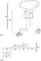
- a telecommunications network 100 is schematically shown, having - preferably - at least a fixed line part.
- a mobile (or cellular) part might be present as well, as part of the telecommunications network 100, but is not specifically illustrated in Figure 1 .
- User equipment or client devices 51, 52 are connected to the telecommunications network 100 by means of a (broadband) access network 120.
- the telecommunications network 100 comprises, especially as part of the broadband access network 120, at least one logical or physical central office point of delivery 110 that is preferably realized within a data center and that is especially handling different access requirements, especially different access possibilities, of the client devices 51, 52 to network functionalities provided by the telecommunications network 100 or via the telecommunications network 100.
- the client devices 51, 52 are typically connected to the logical or physical central office point of delivery 110 by means of a customer premises equipment device 50, 50' or by means of a customer premises equipment functionality that might be built in the client devices 51, 52.
- the central office point of delivery 110 comprises a switching fabric 115 comprising a plurality of spine network nodes and typically also a plurality of leaf network nodes which are not explicitly represented in Figure 1 .
- FIG. 2 schematically shows in greater detail the central office point of delivery 110 as part of the broadband access network 120 of the telecommunications network 100, the central office point of delivery 110 comprising a certain number of components, entities and/or network nodes, as well as further entities and/or network nodes being connected thereto.
- the represented part of the telecommunications network 100 comprises the switching fabric 115 comprising a plurality of spine network nodes 171, 172 and typically also a plurality of leaf network nodes 161, 162, 163, 164.
- the leaf network nodes 161, 162, 163, 164 typically comprise or host the functionality of service edge nodes or entities.
- FIG. 161 shows an access node 151 (being representative for, typically, a number of such access nodes or a plurality of access nodes typically present within the broadband access network 120.
- Such access nodes typically include line termination nodes, wherein, typically, each of the line termination nodes has one or a plurality of access node ports (not specifically illustrated in Figure 2 ).
- the line termination nodes or access nodes might be provided to support different access technologies (e.g. DSL, digital subscriber line technologies, or line termination nodes supporting to be connected to an optical network, especially a passive optical network (PON), typically a so-called optical line terminal (OLT) or optical line terminal device) to a home gateway or customer premises equipment 50, 50' (represented in Figure 1 but not in Figure 2 ).
- PON passive optical network
- OLT optical line terminal
- a client device 51 is connected to the telecommunications network 100 (i.e.
- the central office point of delivery 110 typically also comprises central nodes or entities providing central functionalities; however, these central nodes or entities are not specifically represented in Figure 2 .
- the broadband access network 120 comprises the central office point of delivery 110 with the switching fabric 115, the switching fabric 115 comprising the plurality of spine network nodes 171, 172 and the plurality of service edge (or leaf) network nodes 161, 162, 163, 164.
- the broadband access network 120 comprises the central office point of delivery 110 with a plurality of service edge network nodes 161, 162, 163, 164, each one of the service edge network nodes 161, 162, 163, 164 realizing at least one service edge instance or functionality, terminating a customer communication link towards a customer premises equipment or an access node 151 (or, typically, terminating a plurality of such customer communication links towards a plurality of customer premises equipments or access nodes).
- the setup or architecture of the broadband access network 120 and/or of the central office point of delivery 110 especially follows Access 4.0 principles and/or ONF's SEBA approach, i.e.
- the broadband access network locations consist of or comprise a network switching fabric 115 and devices connected to it at the leaf switch layer (leaf network nodes) while the spine switch layer (spine network nodes) provide the uplink to the IP core network (not represented in Figure 2 ).
- the access node 151 which is, e.g., an OLT but can also be an MSAN, connects to the leaf switch (or service edge network node) and in a preferred scenario, the leaf switch hosts what is denoted as the service edge (SE).
- SE service edge
- the service edge terminates the layer 2 tunnels (stacked VLANs or MPLS tunnels or combinations thereof) from the subscribers' customer premises equipments.
- the subscriber's tunnels end and only the IP addresses assigned to the specific subscriber are "seen" from the network; those may well be encapsulated in L2 tunnels throughout the switching fabric.
- the service edge functionality might become a single point of failure, i.e. if the node hosting the service edge functionality or the running application or instance realizing the service edge functionality fails, the related customer or subscriber sessions fail as well.
- the present invention provides the possibility to realize redundancy at the service edge level where the subscriber tunnels (PPPoE or IPoE over any L2 technology) are terminated.
- the service edge network nodes 161, 162, 163, 164 - and especially a first service edge network node 161 and a second service edge network node 162 - comprise, respectively, a forwarding hardware part or module, and a control hardware part or module.
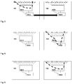
- This is schematically represented in Figures 3, 4 and 5 , which schematically illustrate, respectively, two service edge network nodes (the first service edge network node 161, and the second service edge network node 162) at different points in time in order to illustrate the inventive method.
- the corresponding forwarding hardware part or module is designated by reference sign 1611, and for the second service edge network node 162, the corresponding forwarding hardware part or module is designated by reference sign 1621).
- the corresponding control hardware part or module is designated by reference sign 1612, and for the second service edge network node 162, the corresponding control hardware part or module is designated by reference sign 1622.
- the service edge (or leaf) network nodes 161, 162, 163, 164 are hereinafter also called switches; a switch has a forwarding plane implemented on an ASIC; this corresponds to the forwarding hardware part or module. Any packet processing is (normally) done on this ASIC.
- the control plane - that resides on the compute board, i.e. the control hardware part or module, on the switch (or in other embodiments even outside on a separate compute device) - also contains the state and is the master. Any time there is a change in state necessary, the control plane on the compute board changes the state of the forwarding entries in the ASIC.
- the at least one service edge instance or functionality realized within or by the first service edge network node 161 and being operational at a point in time, corresponds to a state information, at or for that point in time, both in the forwarding hardware part or module 1611, and in the control hardware part or module 1612 of the first service edge network node 161.
- This means that the at least one service edge instance or functionality - e.g.
- a virtual machine instance or an instance of a software product running either directly on the first service edge network node 161, or running within a virtual machine running on the first service edge network node 161 - has or comprises or corresponds, at each point in time (or, strictly speaking, at least at every processor clock cycle or at every few processor clock cycles), to a configuration or state, especially a configuration or state of its forwarding hardware part or module 1611, wherein this configuration or state is potentially altered successively every processor clock cycle or every few processor clock cycles.
- This configuration or state is called the state information, and this state information, at least in general, differs at different points in time.
- the method comprises the following steps:
- the syncing, within the first step might either comprise (as or regarding the source of the syncing)
- the syncing within the first step, might either comprise (as or regarding the destination of the syncing)
- the syncing that is occurring during the first step is represented, in Figure 3 , by means of a bold arrow pointing from the control hardware part or module 1612 of the first service edge network node 161 towards the control hardware part or module 1622 of the second service edge network node 162 (in order to indicate that, at least, a syncing of state information to the control hardware part or module 1622 of the second service edge network node 162 occurs; however, the other syncing alternatives, as described in this paragraph, are possible to be implemented as well).
- the dashed line shown in Figure 3 regarding the first service edge network node 161 represents the configuration (especially routing tables, etc.) of the control hardware part or module 1612 of the first service edge network node 161.
- the second step is invoked in case of failure of the first service edge network node 161 (and/or in case of failure of the at least one service edge instance or functionality running on the first service edge network node 161) and is represented in both Figures 4 and 5 . If such a failure happens, the synced state information (or the synced part of the state information of the first service edge network node 161) on the second service edge network node 162 (synced during the first step) is used to implement or to execute, on the second service edge network node, as soon as possible and to an extend as complete as possible (and progressively to an ever larger extend) the functionality of the first service edge network node 161 (or of the (failed) service edge instance or functionality previously running on the first service edge network node 161), i.e. the functionality of the first service edge network node 161 is taken over by (or handed over to) the second service edge network node 162.
- this handover of the functionality of the first service edge network node 161 (by the second service edge network node 161) is realized by means of:
- a dashed line in Figure 4 regarding the second service edge network node 162 is intended to represent the intermediate situation of the first sup-step of the second step, during which the synced state information is not yet completely present in the second service edge network node 162, especially not completely present in the forwarding hardware part or module 1621 of the second service edge network node 162.
- the most essential (or the most time sensitive (or latency sensitive)) traffic is preferably routed via the control hardware part or module 1622 of the second service edge network node 162.
- a dashed line in Figure 5 regarding the second service edge network node 162 and corresponding to the dashed line in Figure 3 is intended to represent the situation in the second sub-step of the second step according to which the second service edge network node 162 has completely taken over the fuctionality of the first service edge network node 161.
- the forwarding state (i.e. the state information) needs to be written on the leaf switch into the embedded ASIC (or other type o chipset like FPGA), i.e. the state information needs to be written in the forwarding hardware part or module 1621 of the second service edge network node 162, which is comparatively time -consuming.
- the forwarding hardware part or module 1621 of the second service edge network node 162 which is comparatively time -consuming.
- the backup device i.e.
- the second service edge network node 162) shall cater as backup for n SE devices (i.e. not only for the first service edge network node 161, but also for a further service edge network node or for a plurality of further service edge network nodes), due to technology inherent limitations, the ASIC (i.e. the forwarding hardware part or module 1621 of the second service edge network node 162) can usually not carry more that the forwarding state of one service edge network node at the same time.
- the present invention provides a solution to realize - in real-time - a redundant session termination function (i.e. a service edge functionality) at minimum outage time with the ability for a n:1 redundancy (i.e.
- a redundant hardware target for an access node's service edge is available, either in the form of a (completely) redundant switch or network node, or in the form of a helper switch (which is the same scenario with the addition that it can be overbooked with regards to the amount on access nodes attached to it as it only needs to cater for the outage of a single service edge).
- the service edge network nodes 161, 162, 163, 164 comprise both the forwarding hardware part or module and the control hardware part or module (typically a PC board that can act like a virtual network function)
- it is advantageously possible according to the present invention to realize the redundancy in a 2-step procedure i.e. by means of the first sub-step and the second sub-step of the second step).
- both control planes i.e. both control hardware parts or modules 1612, 1622
- both control planes i.e. both control hardware parts or modules 1612, 1622
- the backup service edge's control plane i.e. the second service edge node 162
- the (complete) device is not activated; this corresponds, on the control plane level (i.e. regarding the control hardware parts or modules 1612, 1622) to a warm standby.
- the control plane on the backup service edge i.e. the second service edge network node 162) is in addition pre-configuring the ASIC (i.e.
- the forwarding hardware part or module 1621 to route all packet traffic through additional lanes or data plane channels (schematically represented in Figures 3, 4 and 5 by means of inclined lines between the respective forwarding and control parts or modules) towards the PC board (i.e. the control hardware part or module 1622).
- additional lanes or data plane channels Schematically represented in Figures 3, 4 and 5 by means of inclined lines between the respective forwarding and control parts or modules
- the PC board i.e. the control hardware part or module 1622
- the ASIC i.e. the forwarding hardware part or module 1621
- the central control plane of the central office point of delivery (usually an software defined network controller) immediately adapts the path from the access nodes concerned to the backup service edge (i.e. the second service edge network node 162) as well as the uplinks of the backup service edge towards the spine switch layer.
- the central control plane of the central office point of delivery usually an software defined network controller
- the subscriber session's e.g. PPPoE session, VoIP call
- first vital functions are available without having had to touch the ASICs forwarding entries (i.e. the configuration of the forwarding hardware part or module 1621).
- the control plane on the backup SE i.e. on the second service edge network node 162 iterates through the subscriber sessions it has cached (as part of syncing the state information) and - running through a priority mechanism that might e.g. prefer enterprise customers - moves the required forwarding state to the ASIC.
- sessions are grouped so that they can be easily classified at the ASIC's ingress packet parser.
- the implementation of the first sub-step of the second step is optional but it reduces the offline time dramatically (typically from minutes to less than a second).
- this multi-stage procedure alleviates the issue with the relatively long time it takes to write state information into ASICs for data backup paths for a service edge network node.
- a fully redundant leaf switch setup available and those leaf switches' service edge functions are not overbooked, it might be conceivable to sync (during the first step) the state information not only to the control hardware part or module but also (completely) to the forwarding hardware part or module; hence the first sub-step of the second step is omitted.
- it might be preferably to realize the discussed multi-stage approach i.e. realized the first sub-step of the second step
- have the local control plane of the backup device i.e.
- the second service edge node 162) handle the communication with the ASIC on its own priority rules.
- a backup mechanism may allow to move state information to the PC board and then have the PC board re-prioritize on the left over leaf switch, possibly cutting lower priority customers off the internet or a TV service while keeping them attached to VoIP and have higher priority customers enjoy full service using the freed resources.
Landscapes
- Engineering & Computer Science (AREA)
- Computer Networks & Wireless Communication (AREA)
- Signal Processing (AREA)
- Data Exchanges In Wide-Area Networks (AREA)
Abstract
Description
- The present invention relates a method for an improved operation of a broadband access network of a telecommunications network and/or for an improved and/or more reliable operation of the broadband access network, the broadband access network comprising a central office point of delivery with a plurality of service edge network nodes, each one of the service edge network nodes realizing at least one service edge instance or functionality, terminating a customer communication link towards a customer premises equipment or an access node.
- Furthermore, the present invention relates to a broadband access network or telecommunications network for an improved operation of a broadband access network of a telecommunications network and/or for an improved and/or more reliable operation of the broadband access network, the broadband access network comprising a central office point of delivery with a plurality of service edge network nodes, each one of the service edge network nodes realizing at least one service edge instance or functionality, terminating a customer communication link towards a customer premises equipment or an access node.
- Additionally, the present invention relates to a service edge network node for an improved operation of an inventive broadband access network of an inventive telecommunications network and/or for an improved and/or more reliable operation of the inventive broadband access network.
- Additionally, the present invention relates to a system for an improved operation of a broadband access network of a telecommunications network and/or for an improved and/or more reliable operation of the broadband access network, the broadband access network comprising a central office point of delivery with a plurality of service edge network nodes, each one of the service edge network nodes realizing at least one service edge instance or functionality, terminating a customer communication link towards a customer premises equipment or an access node.
- Furthermore, the present invention relates to a program and a computer-readable medium for an improved operation of a broadband access network of a telecommunications network and/or for an improved and/or more reliable operation of the broadband access network.
- The exchange of packetized information in broadband communication systems or telecommunications networks, both in fixed-line as in wireless communication systems (or fixed-line communication networks and mobile communication networks) has already grown dramatically and probably will also grow in the future due to the rapid spread of different data services in such communication networks.
- In conventionally known or current central office point of delivery design architecture(s), the service edge node or service edge functionality is often a single point of failure as it typically terminates the subscriber session and/or corresponds to a termination of a layer 2 tunnel from the subscriber's customer premises equipment (or corresponding device or entity). Hence, an efficient way of realizing a more reliable operation is required.
- An object of the present invention is to provide a technically simple, effective and cost effective solution for an improved operation of a broadband access network of a telecommunications network and/or for an improved and/or more reliable operation of the broadband access network, the broadband access network comprising a central office point of delivery with a plurality of service edge network nodes, each one of the service edge network nodes realizing at least one service edge instance or functionality, terminating a customer communication link towards a customer premises equipment or an access node. A further object of the present invention is to provide a corresponding broadband access network or telecommunications network, a corresponding service edge network node and a corresponding system for an improved operation of a broadband access network of a telecommunications network and/or for an improved and/or more reliable operation of the broadband access network.
- The object of the present invention is achieved by a method for an improved operation of a broadband access network of a telecommunications network and/or for an improved and/or more reliable operation of the broadband access network, the broadband access network comprising a central office point of delivery with a plurality of service edge network nodes, each one of the service edge network nodes realizing at least one service edge instance or functionality, terminating a customer communication link towards a customer premises equipment or an access node,
wherein a first service edge network node and a second service edge network node comprises, respectively, a forwarding hardware part or module, and a control hardware part or module, wherein the at least one service edge instance or functionality, realized within or by the first service edge network node and being operational at a point in time, corresponds to a state information, at or for that point in time, both in the forwarding hardware part or module, and in the control hardware part or module of the first service edge network node,
wherein in order for an improved and/or more reliable operation of the central office point of delivery, the method comprises the following steps: - -- in a first step, the state information regarding the at least one service edge instance or functionality realized within or by the first service edge network node is continuously synced at least to the control hardware part or module of the second service edge network node,
- -- in a second step, subsequent to the first step and in case of failure of the first service edge network node, the second service edge network node realizes the at least one service edge instance or functionality - previously realized within or by the first service edge network node - by means of using the continuously synced state information.
- It is thereby advantageously possible according to the present invention to provide a solution such that it is avoided that the service edge instance or functionality is a single point of failure. Thereby, it is advantageously possible to provide for a more reliable operation of the broadband access network. Especially, it is advantageously possible according to the present invention that a higher level of redundancy is able to be provided regarding the service edge instance or functionality and/or at a network node where the subscriber tunnels (typically PPPoE, point-to-point-protocol over Ethernet or IPoE, internet protocol over Ethernet) over any layer 2 technology are terminated.
- According to the present invention, the broadband access network typically comprises a central office point of delivery with a plurality of service edge network nodes, each one of the service edge network nodes realizing at least one service edge instance or functionality, terminating a customer communication link towards a customer premises equipment or an access node. In the context of the present invention, especially a first service edge network node and a second service edge network node are considered, both of which comprise, respectively, a forwarding hardware part or module, and a control hardware part or module. The at least one service edge instance or functionality, realized within or by the first service edge network node and being operational at a point in time, corresponds to a state information, at or for that point in time, both in the forwarding hardware part or module, and in the control hardware part or module of the first service edge network node. According to the present invention, in order for an improved and/or more reliable operation of the central office point of delivery, the method comprises the steps of continuously syncing the state information (regarding the at least one service edge instance or functionality realized within or by the first service edge network node) at least to the control hardware part or module of the second service edge network node, and, in case of failure of the first service edge network node, the second service edge network node realizing the at least one service edge instance or functionality - previously realized within or by the first service edge network node - by means of using the continuously synced state information.
- According to the present invention, a solution is provided for the problem of writing a state information quickly to the forwarding hardware part or module. In conventionally known virtualized environments (such as server-based virtual network functions), there typically exist multiple ways to provide redundancy, e.g. in the form of session cloning, or in the form of n:1, of n:m redundancy, etc. In such a scenario, it is rather easy to clone the state (i.e. a state information) between two instances of a network node (e.g. a service edge network node) and then, in case of a failure, route the corresponding or affected tunnels (i.e. subscriber sessions) to another network node (in the considered case typically another service edge network node or instance) that takes over the handling of these sessions. The reason for this is that writing the forwarding state (i.e. corresponding to the state information) on x86 architectures is able to be conducted very fast. However, in the scenario considered according to the present invention, the service edge network nodes comprise a forwarding hardware part or module and a control hardware part or module, wherein the forwarding hardware part or module is typically an ASIC (application specific integrated circuit) or another type of chipset such as a FPGA (field programmable gate array), typically having the property of being able to very quickly perform specialized tasks (for which such circuits are intended and provided) but having also the property that writing state information to or onto such ASICs or other chipsets as FPGAs is comparatively time-consuming. Hence, even in case a redundant (service edge) network node would be held present (for every considered operational (service edge) network node), it would be hard if not impossible to continuously keep the state of the redundant network node in sync with the operational network node.
According to a further preferred embodiment of the present invention or according to further embodiments, multiple ASICs, i.e. multiple separate ASICs, might be part on one board, i.e. on one service edge network node; of course, this can be the case for a certain number of the plurality of service edge network nodes. In such an embodiment, the multiple ASICs collectively form the forwarding hardware part or module (of the respective service edge network node or service edge network nodes). - The telecommunications network according to the present invention might be a fixed-line telecommunications network or a mobile communication network but could also have both aspects, i.e. parts of a fixed-line telecommunications network (or being a fixed-line telecommunications network in such parts) and parts of a mobile communication network (or being a mobile communication network in such parts); such networks are also known under the term fixed-mobile-convergence networks (FMC networks).
- Furthermore, it is advantageously possible and preferred according to the present invention that in a first sub-step of the second step, subsequent to the first step and in case of failure or scheduled downtime of the first service edge network node, the method comprises the synced state information being present only in or at least primarily in the control hardware part or module of the second service edge network node, whereas the synced state information being at least not completely present in the forwarding hardware part or module of the second service edge network node, and the second service edge network node partly realizing the at least one service edge instance or functionality previously realized within or by the first service edge network node, wherein in a second sub-step of the second step, subsequent to the first sub-step of the second step, the method comprises the synced state information being present both in the control hardware part or module, and in the forwarding hardware part or module of the second service edge network node, and the second service edge network node fully realizing the at least one service edge instance or functionality previously realized within or by the first service edge network node.
- Thereby, it is advantageously possible according to the present invention to quickly route high priority traffic, even after a failure of the first service edge network node.
- According to a further preferred embodiment of the present invention, continuously syncing, during the first step, the state information regarding the at least one service edge instance or functionality realized within or by the first service edge network node involves syncing the state information as well as any changes currently occurring regarding this state information to the control hardware part or module of the second service edge network node, especially continuously maintaining a warm standby, within the second service edge network node, of the state of the at least one service edge instance or functionality, but preferably of a plurality of service edge entities or functionalities realized within or by the first service edge network node, and especially continuously maintaining a warm standby, within the second service edge network node, of the states of a plurality of service edge entities or functionalities realized within or by the first service edge network node as well as at least one further service edge network node,
wherein especially the control hardware part or module of the first service edge network node and the control hardware part or module of the second service edge network node realize, respectively, a control plane regarding their respective first and second service edge network nodes, and wherein especially the forwarding hardware part or module of the second service edge network node is inactivated during the first step or during the warm standby,
wherein especially continuously syncing, during the first step, the state information regarding the at least one service edge instance or functionality realized within or by the first service edge network node involves syncing the state information, as well as any changes, - -- either using an in-band communication through one of the plurality of spine network nodes,
- -- or a management network or control plane communication within the central office point of delivery, especially a bottom-of-rack switch.
- Thereby, it is advantageously possible according to the present invention to provide for a more reliable operation of the inventive broadband access network.
- According to a further embodiment of the present invention, during the first sub-step of the second step, subsequent to the first step and in case of failure of the first service edge network node, the method comprises the synced state information being present only in or at least primarily in the control hardware part or module of the second service edge network node, and the synced state information being at least not completely present in the forwarding hardware part or module of the second service edge network node, and the second service edge network node only partly realizing the at least one service edge instance or functionality previously realized within or by the first service edge network node,
wherein especially the second service edge network node realizes the at least one service edge instance or functionality - previously realized within or by the first service edge network node - with regard to prioritized user traffic only, especially traffic within specific traffic classes, especially voice over IP traffic, and/or traffic regarding specific classes of customers. - Thereby, it is advantageously possible to reduce traffic interruptions as much as possible and to limit such traffic interruptions preferably to lower priority traffic and/or to higher latency traffic.
- Furthermore, according to a preferred embodiment of the present invention, during the first sub-step of the second step, subsequent to the first step and in case of failure of the first service edge network node, the method comprises routing the prioritized user traffic via the control hardware part or module of the second service edge network node, especially by means of using data plane channels between the forwarding hardware part or module and the control hardware part or module of the second service edge network node,
wherein especially the forwarding hardware part or module of the second service edge network node is preconfigured, especially prior to the first sub-step of the second step, such that all data plane traffic is routed through the data plane channels between the forwarding hardware part or module and the control hardware part or module of the second service edge network node. - Thereby, it is advantageously possible to almost immediately recover from a failure of the first service edge network node, at least for a part of the concerned traffic.
- According to a further embodiment of the present invention, during the first sub-step of the second step, subsequent to the first step and in case of failure of the first service edge network node, the method comprises progressively configuring the forwarding hardware part or module of the second service edge network node - especially by means of a control channel between the control hardware part or module and the forwarding hardware part or module of the second service edge network node - in order to realize the at least one service edge instance or functionality, previously realized within or by the first service edge network node, also regarding the lower priority user plane traffic, and thereby progressively entering or realizing the second sub-step of the second step by means of the synced state information being present both in the control hardware part or module, and in the forwarding hardware part or module of the second service edge network node.
- Thereby, it is advantageously possible to progressively realize the complete functionality of the failed service edge network node.
- According to a further embodiment of the present invention, in the second step, the synced state information is at first present only in or at least primarily only in the control hardware part or module of the second service edge network node - and the synced state information being not at all, or, at least not completely, present in the forwarding hardware part or module of the second service edge network node - , and the second service edge network node progressively realizing the at least one service edge instance or functionality, previously realized within or by the first service edge network node, by means of progressively configuring the forwarding hardware part or module of the second service edge network node - especially by means of a control channel between the control hardware part or module and the forwarding hardware part or module of the second service edge network node.
- Thereby, it is advantageously possible to easily and effectively implement the inventive method.
- Furthermore, according to an embodiment of the present invention, the central office point of delivery comprises a switching fabric, the switching fabric comprising a plurality of spine network nodes and a plurality of leaf network nodes, wherein the leaf network nodes correspond to or host or co-host the service edge network nodes,
wherein especially the central office point of delivery and/or the broadband access network comprise(s) a plurality of line termination nodes, wherein each one of the plurality of line termination nodes is connected to at least two service edge network nodes of the plurality of service edge network nodes, wherein especially each one of the plurality of service edge network nodes is connected to at least two spine network nodes of the plurality of spine network nodes. - Thereby, it is advantageously possible to easily and effectively implement the inventive method.
- Furthermore, the present invention relates to a broadband access network or telecommunications network for an improved operation of a broadband access network of a telecommunications network and/or for an improved and/or more reliable operation of the broadband access network, the broadband access network comprising a central office point of delivery with a plurality of service edge network nodes, each one of the service edge network nodes realizing at least one service edge instance or functionality, terminating a customer communication link towards a customer premises equipment or an access node,
wherein a first service edge network node and a second service edge network node comprises, respectively, a forwarding hardware part or module, and a control hardware part or module, wherein the at least one service edge instance or functionality, realized within or by the first service edge network node and being operational at a point in time, corresponds to a state information, at or for that point in time, both in the forwarding hardware part or module, and in the control hardware part or module of the first service edge network node,
wherein in order for an improved and/or more reliable operation of the central office point of delivery, the broadband access network or the telecommunications network is configured such that: - -- the state information regarding the at least one service edge instance or functionality realized within or by the first service edge network node is continuously synced at least to the control hardware part or module of the second service edge network node,
- -- in case of failure of the first service edge network node, the second service edge network node realizes the at least one service edge instance or functionality - previously realized within or by the first service edge network node - by means of using the continuously synced state information.
- Furthermore, the present invention relates to a service edge network node for an improved operation of an inventive broadband access network of an inventive telecommunications network and/or for an improved and/or more reliable operation of the inventive broadband access network or the inventive telecommunications network.
- Additionally, the present invention relates to a system for an improved operation of a broadband access network of a telecommunications network and/or for an improved and/or more reliable operation of the broadband access network, the broadband access network comprising a central office point of delivery with a plurality of service edge network nodes, each one of the service edge network nodes realizing at least one service edge instance or functionality, terminating a customer communication link towards a customer premises equipment or an access node,
wherein a first service edge network node and a second service edge network node comprises, respectively, a forwarding hardware part or module, and a control hardware part or module, wherein the at least one service edge instance or functionality, realized within or by the first service edge network node and being operational at a point in time, corresponds to a state information, at or for that point in time, both in the forwarding hardware part or module, and in the control hardware part or module of the first service edge network node,
wherein in order for an improved and/or more reliable operation of the central office point of delivery, the system is configured such that: - -- the state information regarding the at least one service edge instance or functionality realized within or by the first service edge network node is continuously synced at least to the control hardware part or module of the second service edge network node,
- -- in case of failure of the first service edge network node, the second service edge network node realizes the at least one service edge instance or functionality - previously realized within or by the first service edge network node - by means of using the continuously synced state information.
- Still additionally, the present invention relates to a program comprising a computer readable program code which, when executed on a computer and/or on a service edge network node and/or on a network node of a switching fabric, or in part on the service edge network node and in part on a network node of a switching fabric, causes the computer and/or the service edge network node and/or the network node of the switching fabric to perform the inventive method.
- Furthermore, the present invention relates to a computer-readable medium comprising instructions which when executed on a computer and/or on a service edge network node and/or on a network node of a switching fabric, or in part on the service edge network node and in part on a network node of a switching fabric, causes the computer and/or the service edge network node and/or the network node of the switching fabric to perform the inventive method.
- These and other characteristics, features and advantages of the present invention will become apparent from the following detailed description, taken in conjunction with the accompanying drawings, which illustrate, by way of example, the principles of the invention. The description is given for the sake of example only, without limiting the scope of the invention. The reference figures quoted below refer to the attached drawings.
-
-
Figure 1 schematically illustrates a telecommunications network according to the present invention, having a broadband access network with a central office point of delivery. -
Figure 2 schematically shows in greater detail the central office point of delivery, especially comprising a switching fabric and a certain number of components, entities and/or network nodes, as well as further entities and/or network nodes being connected to the central office point of delivery. -
Figures 3, 4 and 5 schematically illustrate, respectively, two service edge network nodes at different points in time in order to illustrate the inventive method. - The present invention will be described with respect to particular embodiments and with reference to certain drawings but the invention is not limited thereto but only by the claims. The drawings described are only schematic and are nonlimiting. In the drawings, the size of some of the elements may be exaggerated and not drawn on scale for illustrative purposes.
- Where an indefinite or definite article is used when referring to a singular noun, e.g. "a", "an", "the", this includes a plural of that noun unless something else is specifically stated.
- Furthermore, the terms first, second, third and the like in the description and in the claims are used for distinguishing between similar elements and not necessarily for describing a sequential or chronological order; this is especially the case for the terms "first step", "second step", etc. It is to be understood that the terms so used are interchangeable under appropriate circumstances and that the embodiments of the invention described herein are capable of operation in other sequences than described or illustrated herein.
- In
Figure 1 , atelecommunications network 100 according to the present invention is schematically shown, having - preferably - at least a fixed line part. A mobile (or cellular) part might be present as well, as part of thetelecommunications network 100, but is not specifically illustrated inFigure 1 . User equipment orclient devices 51, 52 are connected to thetelecommunications network 100 by means of a (broadband)access network 120. Thetelecommunications network 100 comprises, especially as part of thebroadband access network 120, at least one logical or physical central office point ofdelivery 110 that is preferably realized within a data center and that is especially handling different access requirements, especially different access possibilities, of theclient devices 51, 52 to network functionalities provided by thetelecommunications network 100 or via thetelecommunications network 100. Theclient devices 51, 52 are typically connected to the logical or physical central office point ofdelivery 110 by means of a customerpremises equipment device 50, 50' or by means of a customer premises equipment functionality that might be built in theclient devices 51, 52. Preferably but not necessarily, the central office point ofdelivery 110 comprises a switchingfabric 115 comprising a plurality of spine network nodes and typically also a plurality of leaf network nodes which are not explicitly represented inFigure 1 . -
Figure 2 schematically shows in greater detail the central office point ofdelivery 110 as part of thebroadband access network 120 of thetelecommunications network 100, the central office point ofdelivery 110 comprising a certain number of components, entities and/or network nodes, as well as further entities and/or network nodes being connected thereto. The represented part of thetelecommunications network 100 comprises the switchingfabric 115 comprising a plurality ofspine network nodes leaf network nodes Figure 2 , theleaf network nodes network nodes figure 2 - leaf network nodes; however, from a functional perspective, thesenetwork nodes edge network nodes leaf network nodes edge network nodes Figure 2 shows an access node 151 (being representative for, typically, a number of such access nodes or a plurality of access nodes typically present within thebroadband access network 120. Such access nodes typically include line termination nodes, wherein, typically, each of the line termination nodes has one or a plurality of access node ports (not specifically illustrated inFigure 2 ). The line termination nodes or access nodes might be provided to support different access technologies (e.g. DSL, digital subscriber line technologies, or line termination nodes supporting to be connected to an optical network, especially a passive optical network (PON), typically a so-called optical line terminal (OLT) or optical line terminal device) to a home gateway orcustomer premises equipment 50, 50' (represented inFigure 1 but not inFigure 2 ). In such a situation, a client device 51 is connected to the telecommunications network 100 (i.e. to the access node 151) via the customer premises equipment 50 (orhome gateway device 50, cf.Figure 1 ), and, if applicable, a network termination node (not specifically shown inFigure 2 ). The functionality of the customer premises equipment 50 (orhome gateway device 50, cf.Figure 1 ) and the functionality of the network termination node might also be integrated in one device or "box". Even the functionality of the client device 51, the functionality of the customer premises equipment 50 (or home gateway device 50) and the functionality of the network termination node might be integrated in one device or "box". In addition to the switchingfabric 115, the central office point ofdelivery 110 typically also comprises central nodes or entities providing central functionalities; however, these central nodes or entities are not specifically represented inFigure 2 . - According to the present invention, a method for an improved operation of a
broadband access network 120 of atelecommunications network 100 and/or for an improved and/or more reliable operation of thebroadband access network 120 is provided. Thebroadband access network 120 comprises the central office point ofdelivery 110 with the switchingfabric 115, the switchingfabric 115 comprising the plurality ofspine network nodes network nodes - Hence, according to the present invention, the
broadband access network 120 comprises the central office point ofdelivery 110 with a plurality of serviceedge network nodes edge network nodes broadband access network 120 and/or of the central office point ofdelivery 110 especially follows Access 4.0 principles and/or ONF's SEBA approach, i.e. the broadband access network locations consist of or comprise anetwork switching fabric 115 and devices connected to it at the leaf switch layer (leaf network nodes) while the spine switch layer (spine network nodes) provide the uplink to the IP core network (not represented inFigure 2 ). Usually, theaccess node 151, which is, e.g., an OLT but can also be an MSAN, connects to the leaf switch (or service edge network node) and in a preferred scenario, the leaf switch hosts what is denoted as the service edge (SE). The service edge (or service edge functionality) terminates the layer 2 tunnels (stacked VLANs or MPLS tunnels or combinations thereof) from the subscribers' customer premises equipments. On its uplink the subscriber's tunnels end and only the IP addresses assigned to the specific subscriber are "seen" from the network; those may well be encapsulated in L2 tunnels throughout the switching fabric. In such a scenario, the service edge functionality might become a single point of failure, i.e. if the node hosting the service edge functionality or the running application or instance realizing the service edge functionality fails, the related customer or subscriber sessions fail as well. The present invention provides the possibility to realize redundancy at the service edge level where the subscriber tunnels (PPPoE or IPoE over any L2 technology) are terminated. - The service
edge network nodes edge network node 161 and a second service edge network node 162 - comprise, respectively, a forwarding hardware part or module, and a control hardware part or module. This is schematically represented inFigures 3, 4 and 5 , which schematically illustrate, respectively, two service edge network nodes (the first serviceedge network node 161, and the second service edge network node 162) at different points in time in order to illustrate the inventive method. - For the first service
edge network node 161, the corresponding forwarding hardware part or module is designated byreference sign 1611, and for the second serviceedge network node 162, the corresponding forwarding hardware part or module is designated by reference sign 1621). For the first serviceedge network node 161, the corresponding control hardware part or module is designated byreference sign 1612, and for the second serviceedge network node 162, the corresponding control hardware part or module is designated byreference sign 1622.
The service edge (or leaf)network nodes - The at least one service edge instance or functionality, realized within or by the first service
edge network node 161 and being operational at a point in time, corresponds to a state information, at or for that point in time, both in the forwarding hardware part ormodule 1611, and in the control hardware part ormodule 1612 of the first serviceedge network node 161. This means that the at least one service edge instance or functionality - e.g. a virtual machine instance or an instance of a software product running either directly on the first serviceedge network node 161, or running within a virtual machine running on the first service edge network node 161 - has or comprises or corresponds, at each point in time (or, strictly speaking, at least at every processor clock cycle or at every few processor clock cycles), to a configuration or state, especially a configuration or state of its forwarding hardware part ormodule 1611, wherein this configuration or state is potentially altered successively every processor clock cycle or every few processor clock cycles. This configuration or state is called the state information, and this state information, at least in general, differs at different points in time. According to the present invention and in order for an improved and/or more reliable operation of the central office point ofdelivery 110, the method comprises the following steps: - -- in a first step, the state information regarding the at least one service edge instance or functionality realized within or by the first service
edge network node 161 is continuously synced at least to the control hardware part ormodule 1622 of the second serviceedge network node 162, - -- in a second step, subsequent to the first step and in case of failure of the first service
edge network node 161, the second serviceedge network node 162 realizes the at least one service edge instance or functionality - previously realized within or by the first service edge network node 161 - by means of using the continuously synced state information. Hence, during the first step, the changes to the state information (applied by the corresponding service edge instance or functionality being operational and being operating, i.e. typically providing communication services to subscribers being served) are continuously synced to the second serviceedge network node 162. - Different embodiments regarding the syncing, within the first step, are conceivable:
The syncing, within the first step, might either comprise (as or regarding the source of the syncing) - -- both a syncing of the state information corresponding to both the control hardware part or
module 1612 and the forwarding hardware part or module 1611 (of the first service edge network node 161), or - -- a syncing of the state information corresponding to the control hardware part or module 1612 (of the first service edge network node 161) only.
- Furthermore, the syncing, within the first step, might either comprise (as or regarding the destination of the syncing)
- -- both a syncing of state information to both the control hardware part or
module 1622 and the forwarding hardware part or module 1621 (of the second service edge network node 162), or - -- a syncing of state information to the control hardware part or module 1622 (of the second service edge network node 162) only.
- The syncing that is occurring during the first step is represented, in
Figure 3 , by means of a bold arrow pointing from the control hardware part ormodule 1612 of the first serviceedge network node 161 towards the control hardware part ormodule 1622 of the second service edge network node 162 (in order to indicate that, at least, a syncing of state information to the control hardware part ormodule 1622 of the second serviceedge network node 162 occurs; however, the other syncing alternatives, as described in this paragraph, are possible to be implemented as well). The dashed line shown inFigure 3 regarding the first serviceedge network node 161 represents the configuration (especially routing tables, etc.) of the control hardware part ormodule 1612 of the first serviceedge network node 161.
The second step is invoked in case of failure of the first service edge network node 161 (and/or in case of failure of the at least one service edge instance or functionality running on the first service edge network node 161) and is represented in bothFigures 4 and 5 . If such a failure happens, the synced state information (or the synced part of the state information of the first service edge network node 161) on the second service edge network node 162 (synced during the first step) is used to implement or to execute, on the second service edge network node, as soon as possible and to an extend as complete as possible (and progressively to an ever larger extend) the functionality of the first service edge network node 161 (or of the (failed) service edge instance or functionality previously running on the first service edge network node 161), i.e. the functionality of the first serviceedge network node 161 is taken over by (or handed over to) the second serviceedge network node 162. - According to a preferred embodiment of the present invention, this handover of the functionality of the first service edge network node 161 (by the second service edge network node 161) is realized by means of:
- -- in a first sub-step of the second step (schematically represented in
Figure 4 ), subsequent to the first step and in case of failure or scheduled downtime of the first serviceedge network node 161, the synced state information being present only in or at least primarily in the control hardware part ormodule 1622 of the second serviceedge network node 162, whereas the synced state information being at least not completely present in the forwarding hardware part ormodule 1621 of the second serviceedge network node 162, and the second serviceedge network node 162 partly realizing the at least one service edge instance or functionality previously realized within or by the first serviceedge network node 161, and - -- in a second sub-step of the second step (schematically represented in
Figure 4 ), subsequent to the first sub-step of the second step, the method comprises the synced state information being present both in the control hardware part ormodule 1622, and in the forwarding hardware part ormodule 1621 of the second serviceedge network node 162, and the second serviceedge network node 162 fully realizing the at least one service edge instance or functionality previously realized within or by the first serviceedge network node 161. - A dashed line in
Figure 4 regarding the second serviceedge network node 162 is intended to represent the intermediate situation of the first sup-step of the second step, during which the synced state information is not yet completely present in the second serviceedge network node 162, especially not completely present in the forwarding hardware part ormodule 1621 of the second serviceedge network node 162. During this intermediate situation, the most essential (or the most time sensitive (or latency sensitive)) traffic is preferably routed via the control hardware part ormodule 1622 of the second serviceedge network node 162. A dashed line inFigure 5 regarding the second serviceedge network node 162 and corresponding to the dashed line inFigure 3 (regarding the first service edge network node 161) is intended to represent the situation in the second sub-step of the second step according to which the second serviceedge network node 162 has completely taken over the fuctionality of the first serviceedge network node 161. - Hence, generally according to the present invention, the forwarding state (i.e. the state information) needs to be written on the leaf switch into the embedded ASIC (or other type o chipset like FPGA), i.e. the state information needs to be written in the forwarding hardware part or
module 1621 of the second serviceedge network node 162, which is comparatively time -consuming. Thus and in contrast to conventionally known server-based virtual network functions, even in the existence of a redundant leaf switch pair per access node (i.e. a first and second serviceedge network node edge network node 161, but also for a further service edge network node or for a plurality of further service edge network nodes), due to technology inherent limitations, the ASIC (i.e. the forwarding hardware part ormodule 1621 of the second service edge network node 162) can usually not carry more that the forwarding state of one service edge network node at the same time. The present invention provides a solution to realize - in real-time - a redundant session termination function (i.e. a service edge functionality) at minimum outage time with the ability for a n:1 redundancy (i.e. a redundant hardware target for an access node's service edge is available, either in the form of a (completely) redundant switch or network node, or in the form of a helper switch (which is the same scenario with the addition that it can be overbooked with regards to the amount on access nodes attached to it as it only needs to cater for the outage of a single service edge). As the serviceedge network nodes - During the first step, the control plane between both SE (i.e. the first and second service
edge network node 161, 162) sync on every state change, thus, both control planes (i.e. both control hardware parts ormodules 1612, 1622) contain the same state. While the backup service edge's control plane (i.e. the second service edge node 162) is filled, the (complete) device is not activated; this corresponds, on the control plane level (i.e. regarding the control hardware parts ormodules 1612, 1622) to a warm standby. The control plane on the backup service edge (i.e. the second service edge network node 162) is in addition pre-configuring the ASIC (i.e. the forwarding hardware part or module 1621) to route all packet traffic through additional lanes or data plane channels (schematically represented inFigures 3, 4 and 5 by means of inclined lines between the respective forwarding and control parts or modules) towards the PC board (i.e. the control hardware part or module 1622). Especially, there is a filter applied that only a reduced amount of subscriber traffic is sent that can be handled by the PC board (i.e. the control hardware part or module 1622) as the ASIC (i.e. the forwarding hardware part or module 1621) is by far more powerful in forwarding packets which is the sole purpose of its existence here. E.g., only voice traffic is routed via the additional lanes or data plane channels towards the PC board, and all other traffic is temporarily (i.e. related to the failure of the first service edge network node 161) dropped.
In case a failover event happens (i.e the first serviceedge network node 161 fails), the central control plane of the central office point of delivery (usually an software defined network controller) immediately adapts the path from the access nodes concerned to the backup service edge (i.e. the second service edge network node 162) as well as the uplinks of the backup service edge towards the spine switch layer. As a traffic subset (of, typically, high priority and/or low latency traffic) is being routed via the CPU (i.e. via the control hardware part or module 1622), the subscriber session's (e.g. PPPoE session, VoIP call) first vital functions are available without having had to touch the ASICs forwarding entries (i.e. the configuration of the forwarding hardware part or module 1621). - Now, the control plane on the backup SE (i.e. on the second service edge network node 162) iterates through the subscriber sessions it has cached (as part of syncing the state information) and - running through a priority mechanism that might e.g. prefer enterprise customers - moves the required forwarding state to the ASIC. According to a preferred embodiment of the present invention, sessions are grouped so that they can be easily classified at the ASIC's ingress packet parser. In case, e.g., that all enterprise customers use an out VLAN tag of value 33: In this case, all sessions for this tag will be written and, once all are moved, the packet parser gets instructed by one single command to stop forwarding the packets to the CPU (via the additional lanes or data plane channels) but now to forward via the ASIC. This needs to be done in parallel with the classification for packets coming from the spine switch (i.e. in reverse direction). Here, usually IP address range-based rules apply.
- The implementation of the first sub-step of the second step is optional but it reduces the offline time dramatically (typically from minutes to less than a second).
- Hence, this multi-stage procedure alleviates the issue with the relatively long time it takes to write state information into ASICs for data backup paths for a service edge network node. In case there is a fully redundant leaf switch setup available and those leaf switches' service edge functions are not overbooked, it might be conceivable to sync (during the first step) the state information not only to the control hardware part or module but also (completely) to the forwarding hardware part or module; hence the first sub-step of the second step is omitted. But even then, it might be preferably to realize the discussed multi-stage approach (i.e. realized the first sub-step of the second step) and have the local control plane of the backup device (i.e. the second service edge node 162) handle the communication with the ASIC on its own priority rules.
In a scenario with redundant leaf switches but lacking capability to cater for (i.e. syncing) all state information on the ASICs or all bandwidth (especially n:1 redundancy, with a helper switch), a backup mechanism may allow to move state information to the PC board and then have the PC board re-prioritize on the left over leaf switch, possibly cutting lower priority customers off the internet or a TV service while keeping them attached to VoIP and have higher priority customers enjoy full service using the freed resources.
Claims (13)
- Method for an improved operation of a broadband access network (120) of a telecommunications network (100) and/or for an improved and/or more reliable operation of the broadband access network (120), the broadband access network (120) comprising a central office point of delivery (110) with a plurality of service edge network nodes (161, 162, 163), each one of the service edge network nodes (161, 162, 163) realizing at least one service edge instance or functionality, terminating a customer communication link towards a customer premises equipment or an access node (151),
wherein a first service edge network node (161) and a second service edge network node (162) comprises, respectively, a forwarding hardware part or module (1611, 1621), and a control hardware part or module (1612, 1622),
wherein the at least one service edge instance or functionality, realized within or by the first service edge network node (161) and being operational at a point in time, corresponds to a state information, at or for that point in time, both in the forwarding hardware part or module (1611), and in the control hardware part or module (1612) of the first service edge network node (161),
wherein in order for an improved and/or more reliable operation of the central office point of delivery (110), the method comprises the following steps:-- in a first step, the state information regarding the at least one service edge instance or functionality realized within or by the first service edge network node (161) is continuously synced at least to the control hardware part or module (1622) of the second service edge network node (162),-- in a second step, subsequent to the first step and in case of failure of the first service edge network node (161), the second service edge network node (162) realizes the at least one service edge instance or functionality - previously realized within or by the first service edge network node (161) - by means of using the continuously synced state information. - Method according to claim 1, wherein in a first sub-step of the second step, subsequent to the first step and in case of failure or scheduled downtime of the first service edge network node (161), the method comprises the synced state information being present only in or at least primarily in the control hardware part or module (1622) of the second service edge network node (162), whereas the synced state information being at least not completely present in the forwarding hardware part or module (1621) of the second service edge network node (162), and the second service edge network node (162) partly realizing the at least one service edge instance or functionality previously realized within or by the first service edge network node (161),
wherein in a second sub-step of the second step, subsequent to the first sub-step of the second step, the method comprises the synced state information being present both in the control hardware part or module (1622), and in the forwarding hardware part or module (1621) of the second service edge network node (162), and the second service edge network node (162) fully realizing the at least one service edge instance or functionality previously realized within or by the first service edge network node (161). - Method according to one of the preceding claims, wherein continuously syncing, during the first step, the state information regarding the at least one service edge instance or functionality realized within or by the first service edge network node (161) involves syncing the state information as well as any changes currently occurring regarding this state information to the control hardware part or module (1622) of the second service edge network node (162), especially continuously maintaining a warm standby, within the second service edge network node (162), of the state of the at least one service edge instance or functionality, but preferably of a plurality of service edge entities or functionalities realized within or by the first service edge network node (161), and especially continuously maintaining a warm standby, within the second service edge network node (162), of the states of a plurality of service edge entities or functionalities realized within or by the first service edge network node (161) as well as at least one further service edge network node,
wherein especially the control hardware part or module (1612) of the first service edge network node (161) and the control hardware part or module (1622) of the second service edge network node (162) realize, respectively, a control plane regarding their respective first and second service edge network nodes (161, 162), and wherein especially the forwarding hardware part or module (1621) of the second service edge network node (162) is inactivated during the first step or during the warm standby,
wherein especially continuously syncing, during the first step, the state information regarding the at least one service edge instance or functionality realized within or by the first service edge network node (161) involves syncing the state information, as well as any changes,-- either using an in-band communication through one of the plurality of spine network nodes (171, 172, 173),-- or a management network or control plane communication within the central office point of delivery (110), especially a bottom-of-rack switch. - Method according to one of the preceding claims, wherein during the first sub-step of the second step, subsequent to the first step and in case of failure of the first service edge network node (161), the method comprises the synced state information being present only in or at least primarily in the control hardware part or module (1622) of the second service edge network node (162), and the synced state information being at least not completely present in the forwarding hardware part or module (1621) of the second service edge network node (162), and the second service edge network node (162) only partly realizing the at least one service edge instance or functionality previously realized within or by the first service edge network node (161),
wherein especially the second service edge network node (162) realizes the at least one service edge instance or functionality - previously realized within or by the first service edge network node (161) - with regard to prioritized user traffic only, especially traffic within specific traffic classes, especially voice over IP traffic, and/or traffic regarding specific classes of customers. - Method according to one of the preceding claims, wherein during the first sub-step of the second step, subsequent to the first step and in case of failure of the first service edge network node (161), the method comprises routing the prioritized user traffic via the control hardware part or module (1622) of the second service edge network node (162), especially by means of using data plane channels between the forwarding hardware part or module (1621) and the control hardware part or module (1622) of the second service edge network node (162),
wherein especially the forwarding hardware part or module (1621) of the second service edge network node (162) is preconfigured, especially prior to the first sub-step of the second step, such that all data plane traffic is routed through the data plane channels between the forwarding hardware part or module (1621) and the control hardware part or module (1622) of the second service edge network node (162). - Method according to one of the preceding claims, wherein during the first sub-step of the second step, subsequent to the first step and in case of failure of the first service edge network node (161), the method comprises progressively configuring the forwarding hardware part or module (1621) of the second service edge network node (162) - especially by means of a control channel between the control hardware part or module (1622) and the forwarding hardware part or module (1621) of the second service edge network node (162) - in order to realize the at least one service edge instance or functionality, previously realized within or by the first service edge network node (161), also regarding the lower priority user plane traffic, and thereby progressively entering or realizing the second sub-step of the second step by means of the synced state information being present both in the control hardware part or module (1622), and in the forwarding hardware part or module (1621) of the second service edge network node (162).
- Method according to one of the preceding claims, wherein, in the second step, the synced state information is at first present only in or at least primarily only in the control hardware part or module (1622) of the second service edge network node (162) - and the synced state information being not at all, or, at least not completely, present in the forwarding hardware part or module (1621) of the second service edge network node (162) - , and the second service edge network node (162) progressively realizing the at least one service edge instance or functionality, previously realized within or by the first service edge network node (161), by means of progressively configuring the forwarding hardware part or module (1621) of the second service edge network node (162) - especially by means of a control channel between the control hardware part or module (1622) and the forwarding hardware part or module (1621) of the second service edge network node (162).
- Method according to one of the preceding claims, wherein the central office point of delivery (110) comprises a switching fabric (115), the switching fabric (115) comprising a plurality of spine network nodes (171, 172, 173) and a plurality of leaf network nodes, wherein the leaf network nodes correspond to or host or co-host the service edge network nodes (161, 162, 163),
wherein especially the central office point of delivery (110) and/or the broadband access network (120) comprise(s) a plurality of line termination nodes (151), wherein each one of the plurality of line termination nodes (151) is connected to at least two service edge network nodes of the plurality of service edge network nodes (161, 162, 163), wherein especially each one of the plurality of service edge network nodes (161, 162, 163) is connected to at least two spine network nodes of the plurality of spine network nodes (171, 172, 173). - Broadband access network (120) or telecommunications network (100) for an improved operation of a broadband access network (120) of a telecommunications network (100) and/or for an improved and/or more reliable operation of the broadband access network (120), the broadband access network (120) comprising a central office point of delivery (110) with a plurality of service edge network nodes (161, 162, 163), each one of the service edge network nodes (161, 162, 163) realizing at least one service edge instance or functionality, terminating a customer communication link towards a customer premises equipment or an access node (151),
wherein a first service edge network node (161) and a second service edge network node (162) comprises, respectively, a forwarding hardware part or module (1611, 1621), and a control hardware part or module (1612, 1622), wherein the at least one service edge instance or functionality, realized within or by the first service edge network node (161) and being operational at a point in time, corresponds to a state information, at or for that point in time, both in the forwarding hardware part or module (1611), and in the control hardware part or module (1612) of the first service edge network node (161),
wherein in order for an improved and/or more reliable operation of the central office point of delivery (110), the broadband access network (120) or the telecommunications network (100) is configured such that:-- the state information regarding the at least one service edge instance or functionality realized within or by the first service edge network node (161) is continuously synced at least to the control hardware part or module (1622) of the second service edge network node (162),-- in case of failure of the first service edge network node (161), the second service edge network node (162) realizes the at least one service edge instance or functionality - previously realized within or by the first service edge network node (161) - by means of using the continuously synced state information. - Service edge network node (161, 162, 163) for an improved operation of a broadband access network (120) of a telecommunications network (100) and/or for an improved and/or more reliable operation of the broadband access network (120) or the telecommunications network (100) according to claim 9.
- System for an improved operation of a broadband access network (120) of a telecommunications network (100) and/or for an improved and/or more reliable operation of the broadband access network (120), the broadband access network (120) comprising a central office point of delivery (110) with a plurality of service edge network nodes (161, 162, 163), each one of the service edge network nodes (161, 162, 163) realizing at least one service edge instance or functionality, terminating a customer communication link towards a customer premises equipment or an access node (151),
wherein a first service edge network node (161) and a second service edge network node (162) comprises, respectively, a forwarding hardware part or module (1611, 1621), and a control hardware part or module (1612, 1622), wherein the at least one service edge instance or functionality, realized within or by the first service edge network node (161) and being operational at a point in time, corresponds to a state information, at or for that point in time, both in the forwarding hardware part or module (1611), and in the control hardware part or module (1612) of the first service edge network node (161),
wherein in order for an improved and/or more reliable operation of the central office point of delivery (110), the system is configured such that:-- the state information regarding the at least one service edge instance or functionality realized within or by the first service edge network node (161) is continuously synced at least to the control hardware part or module (1622) of the second service edge network node (162),-- in case of failure of the first service edge network node (161), the second service edge network node (162) realizes the at least one service edge instance or functionality - previously realized within or by the first service edge network node (161) - by means of using the continuously synced state information. - Program comprising a computer readable program code which, when executed on a computer and/or on a service edge network node (161, 162, 163) and/or on a network node of a switching fabric (115), or in part on the service edge network node (161, 162, 163) and in part on a network node of a switching fabric (115), causes the computer and/or the service edge network node (161, 162, 163) and/or the network node of the switching fabric (115) to perform a method according one of claims 1 to 8.
- Computer-readable medium comprising instructions which when executed on a computer and/or on a service edge network node (161, 162, 163) and/or on a network node of a switching fabric (115), or in part on the service edge network node (161, 162, 163) and in part on a network node of a switching fabric (115), causes the computer and/or the service edge network node (161, 162, 163) and/or the network node of the switching fabric (115) to perform a method according one of claims 1 to 8.
Priority Applications (2)
| Application Number | Priority Date | Filing Date | Title |
|---|---|---|---|
| EP20160218.2A EP3873036B1 (en) | 2020-02-28 | 2020-02-28 | Method for an improved operation of a broadband access network of a telecommunications network and/or for an improved and/or more reliable operation of the broadband access network, broadband access network or telecommunications network, and system, program and computer-readable medium |
| ES20160218T ES2950720T3 (en) | 2020-02-28 | 2020-02-28 | Procedure for improved operation of a broadband access network of a telecommunications network and/or for improved and/or more reliable operation of the broadband access network, broadband access network or telecommunications network , and the system, program and computer-readable medium |
Applications Claiming Priority (1)
| Application Number | Priority Date | Filing Date | Title |
|---|---|---|---|
| EP20160218.2A EP3873036B1 (en) | 2020-02-28 | 2020-02-28 | Method for an improved operation of a broadband access network of a telecommunications network and/or for an improved and/or more reliable operation of the broadband access network, broadband access network or telecommunications network, and system, program and computer-readable medium |
Publications (2)
| Publication Number | Publication Date |
|---|---|
| EP3873036A1 true EP3873036A1 (en) | 2021-09-01 |
| EP3873036B1 EP3873036B1 (en) | 2023-06-21 |
Family
ID=69770382
Family Applications (1)
| Application Number | Title | Priority Date | Filing Date |
|---|---|---|---|
| EP20160218.2A Active EP3873036B1 (en) | 2020-02-28 | 2020-02-28 | Method for an improved operation of a broadband access network of a telecommunications network and/or for an improved and/or more reliable operation of the broadband access network, broadband access network or telecommunications network, and system, program and computer-readable medium |
Country Status (2)
| Country | Link |
|---|---|
| EP (1) | EP3873036B1 (en) |
| ES (1) | ES2950720T3 (en) |
Citations (4)
| Publication number | Priority date | Publication date | Assignee | Title |
|---|---|---|---|---|
| US20110134931A1 (en) * | 2009-12-08 | 2011-06-09 | Jacobus Van Der Merwe | Virtual router migration |
| WO2013144746A1 (en) * | 2012-03-28 | 2013-10-03 | Telefonaktiebolaget L M Ericsson (Publ) | Inter-chassis redundancy with coordinated traffic direction |
| WO2018192884A1 (en) * | 2017-04-18 | 2018-10-25 | Deutsche Telekom Ag | Method for enhanced handling of multicast data streams within a broadband access network of a telecommunications network, telecommunications network, and system for enhanced handling of multicast data streams within a broadband access network of a telecommunications network, program and computer program product |
| US20180352036A1 (en) * | 2017-05-31 | 2018-12-06 | Affirmed Networks, Inc. | Decoupled control and data plane synchronization for ipsec geographic redundancy |
-
2020
- 2020-02-28 EP EP20160218.2A patent/EP3873036B1/en active Active
- 2020-02-28 ES ES20160218T patent/ES2950720T3/en active Active
Patent Citations (4)
| Publication number | Priority date | Publication date | Assignee | Title |
|---|---|---|---|---|
| US20110134931A1 (en) * | 2009-12-08 | 2011-06-09 | Jacobus Van Der Merwe | Virtual router migration |
| WO2013144746A1 (en) * | 2012-03-28 | 2013-10-03 | Telefonaktiebolaget L M Ericsson (Publ) | Inter-chassis redundancy with coordinated traffic direction |
| WO2018192884A1 (en) * | 2017-04-18 | 2018-10-25 | Deutsche Telekom Ag | Method for enhanced handling of multicast data streams within a broadband access network of a telecommunications network, telecommunications network, and system for enhanced handling of multicast data streams within a broadband access network of a telecommunications network, program and computer program product |
| US20180352036A1 (en) * | 2017-05-31 | 2018-12-06 | Affirmed Networks, Inc. | Decoupled control and data plane synchronization for ipsec geographic redundancy |
Also Published As
| Publication number | Publication date |
|---|---|
| EP3873036B1 (en) | 2023-06-21 |
| ES2950720T3 (en) | 2023-10-13 |
Similar Documents
| Publication | Publication Date | Title |
|---|---|---|
| US12255812B1 (en) | Service chaining among devices of interconnected topology | |
| CN110098992B (en) | Private virtual local area network for transporting peer-to-peer traffic between switches | |
| US10999125B1 (en) | Inter-application communication via signal-routes | |
| EP3605968B1 (en) | N:1 stateful application gateway redundancy model | |
| US10225179B2 (en) | Virtual port channel bounce in overlay network | |
| EP2536068B1 (en) | Virtual subscriber management | |
| EP2640013B1 (en) | Method And Apparatus Providing Network Redundancy And High Availability To Remote Network Nodes | |
| CN117121456A (en) | Architecture for deaggregating SDN from hosts | |
| US9380111B2 (en) | Feature peer network with scalable state information | |
| US9641354B2 (en) | Virtual cable modem termination system | |
| US8699327B2 (en) | Multipath virtual router redundancy | |
| US20180018195A1 (en) | System for providing virtual customer premises equipment services in network function virtualization environment, and network function virtualization cloud for the same | |
| US20170063604A1 (en) | Method and apparatus for sve redundancy | |
| US20140067983A1 (en) | Bi-directional synchronization enabling active-active redundancy for load-balancing switches | |
| US8446818B2 (en) | Routed split multi-link trunking resiliency for wireless local area network split-plane environments | |
| US11424978B2 (en) | Fast forwarding re-convergence of switch fabric multi-destination packets triggered by link failures | |
| CN117203615A (en) | Extending host policies via distribution | |
| US6973024B1 (en) | Method for modem element switchover using multicast groups | |
| US11251245B1 (en) | Responding to a failure of a main die of a switch data-plane device | |
| EP3873036B1 (en) | Method for an improved operation of a broadband access network of a telecommunications network and/or for an improved and/or more reliable operation of the broadband access network, broadband access network or telecommunications network, and system, program and computer-readable medium | |
| US10756813B1 (en) | Broadband subscriber switchover in a ring network | |
| US10225102B2 (en) | Network connectivity | |
| EP1583304B1 (en) | Media gateway | |
| De Lima et al. | RESISTING: A new fast-reroute mechanism with packet distribution on P4-programmable switches | |
| US12603812B2 (en) | Virtual internet protocol address associated with subscriber group |
Legal Events
| Date | Code | Title | Description |
|---|---|---|---|
| PUAI | Public reference made under article 153(3) epc to a published international application that has entered the european phase |
Free format text: ORIGINAL CODE: 0009012 |
|
| STAA | Information on the status of an ep patent application or granted ep patent |
Free format text: STATUS: THE APPLICATION HAS BEEN PUBLISHED |
|
| AK | Designated contracting states |
Kind code of ref document: A1 Designated state(s): AL AT BE BG CH CY CZ DE DK EE ES FI FR GB GR HR HU IE IS IT LI LT LU LV MC MK MT NL NO PL PT RO RS SE SI SK SM TR |
|
| STAA | Information on the status of an ep patent application or granted ep patent |
Free format text: STATUS: REQUEST FOR EXAMINATION WAS MADE |
|
| 17P | Request for examination filed |
Effective date: 20220301 |
|
| RBV | Designated contracting states (corrected) |
Designated state(s): AL AT BE BG CH CY CZ DE DK EE ES FI FR GB GR HR HU IE IS IT LI LT LU LV MC MK MT NL NO PL PT RO RS SE SI SK SM TR |
|
| GRAP | Despatch of communication of intention to grant a patent |
Free format text: ORIGINAL CODE: EPIDOSNIGR1 |
|
| STAA | Information on the status of an ep patent application or granted ep patent |
Free format text: STATUS: GRANT OF PATENT IS INTENDED |
|
| RIC1 | Information provided on ipc code assigned before grant |
Ipc: H04L 41/0668 20220101ALI20230214BHEP Ipc: H04L 12/28 20060101AFI20230214BHEP |
|
| INTG | Intention to grant announced |
Effective date: 20230307 |
|
| GRAS | Grant fee paid |
Free format text: ORIGINAL CODE: EPIDOSNIGR3 |
|
| GRAA | (expected) grant |
Free format text: ORIGINAL CODE: 0009210 |
|
| STAA | Information on the status of an ep patent application or granted ep patent |
Free format text: STATUS: THE PATENT HAS BEEN GRANTED |
|
| AK | Designated contracting states |
Kind code of ref document: B1 Designated state(s): AL AT BE BG CH CY CZ DE DK EE ES FI FR GB GR HR HU IE IS IT LI LT LU LV MC MK MT NL NO PL PT RO RS SE SI SK SM TR |
|
| REG | Reference to a national code |
Ref country code: CH Ref legal event code: EP |
|
| REG | Reference to a national code |
Ref country code: DE Ref legal event code: R096 Ref document number: 602020012644 Country of ref document: DE |
|
| REG | Reference to a national code |
Ref country code: AT Ref legal event code: REF Ref document number: 1581707 Country of ref document: AT Kind code of ref document: T Effective date: 20230715 |
|
| REG | Reference to a national code |
Ref country code: IE Ref legal event code: FG4D |
|
| REG | Reference to a national code |
Ref country code: LT Ref legal event code: MG9D |
|
| REG | Reference to a national code |
Ref country code: ES Ref legal event code: FG2A Ref document number: 2950720 Country of ref document: ES Kind code of ref document: T3 Effective date: 20231013 |
|
| REG | Reference to a national code |
Ref country code: NL Ref legal event code: MP Effective date: 20230621 |
|
| PG25 | Lapsed in a contracting state [announced via postgrant information from national office to epo] |
Ref country code: SE Free format text: LAPSE BECAUSE OF FAILURE TO SUBMIT A TRANSLATION OF THE DESCRIPTION OR TO PAY THE FEE WITHIN THE PRESCRIBED TIME-LIMIT Effective date: 20230621 Ref country code: NO Free format text: LAPSE BECAUSE OF FAILURE TO SUBMIT A TRANSLATION OF THE DESCRIPTION OR TO PAY THE FEE WITHIN THE PRESCRIBED TIME-LIMIT Effective date: 20230921 |
|
| REG | Reference to a national code |
Ref country code: AT Ref legal event code: MK05 Ref document number: 1581707 Country of ref document: AT Kind code of ref document: T Effective date: 20230621 |
|
| PG25 | Lapsed in a contracting state [announced via postgrant information from national office to epo] |
Ref country code: RS Free format text: LAPSE BECAUSE OF FAILURE TO SUBMIT A TRANSLATION OF THE DESCRIPTION OR TO PAY THE FEE WITHIN THE PRESCRIBED TIME-LIMIT Effective date: 20230621 Ref country code: NL Free format text: LAPSE BECAUSE OF FAILURE TO SUBMIT A TRANSLATION OF THE DESCRIPTION OR TO PAY THE FEE WITHIN THE PRESCRIBED TIME-LIMIT Effective date: 20230621 Ref country code: LV Free format text: LAPSE BECAUSE OF FAILURE TO SUBMIT A TRANSLATION OF THE DESCRIPTION OR TO PAY THE FEE WITHIN THE PRESCRIBED TIME-LIMIT Effective date: 20230621 Ref country code: LT Free format text: LAPSE BECAUSE OF FAILURE TO SUBMIT A TRANSLATION OF THE DESCRIPTION OR TO PAY THE FEE WITHIN THE PRESCRIBED TIME-LIMIT Effective date: 20230621 Ref country code: HR Free format text: LAPSE BECAUSE OF FAILURE TO SUBMIT A TRANSLATION OF THE DESCRIPTION OR TO PAY THE FEE WITHIN THE PRESCRIBED TIME-LIMIT Effective date: 20230621 Ref country code: GR Free format text: LAPSE BECAUSE OF FAILURE TO SUBMIT A TRANSLATION OF THE DESCRIPTION OR TO PAY THE FEE WITHIN THE PRESCRIBED TIME-LIMIT Effective date: 20230922 |
|
| PG25 | Lapsed in a contracting state [announced via postgrant information from national office to epo] |
Ref country code: FI Free format text: LAPSE BECAUSE OF FAILURE TO SUBMIT A TRANSLATION OF THE DESCRIPTION OR TO PAY THE FEE WITHIN THE PRESCRIBED TIME-LIMIT Effective date: 20230621 |
|
| PG25 | Lapsed in a contracting state [announced via postgrant information from national office to epo] |
Ref country code: SK Free format text: LAPSE BECAUSE OF FAILURE TO SUBMIT A TRANSLATION OF THE DESCRIPTION OR TO PAY THE FEE WITHIN THE PRESCRIBED TIME-LIMIT Effective date: 20230621 |
|
| PG25 | Lapsed in a contracting state [announced via postgrant information from national office to epo] |
Ref country code: IS Free format text: LAPSE BECAUSE OF FAILURE TO SUBMIT A TRANSLATION OF THE DESCRIPTION OR TO PAY THE FEE WITHIN THE PRESCRIBED TIME-LIMIT Effective date: 20231021 |
|
| PG25 | Lapsed in a contracting state [announced via postgrant information from national office to epo] |
Ref country code: SM Free format text: LAPSE BECAUSE OF FAILURE TO SUBMIT A TRANSLATION OF THE DESCRIPTION OR TO PAY THE FEE WITHIN THE PRESCRIBED TIME-LIMIT Effective date: 20230621 Ref country code: SK Free format text: LAPSE BECAUSE OF FAILURE TO SUBMIT A TRANSLATION OF THE DESCRIPTION OR TO PAY THE FEE WITHIN THE PRESCRIBED TIME-LIMIT Effective date: 20230621 Ref country code: RO Free format text: LAPSE BECAUSE OF FAILURE TO SUBMIT A TRANSLATION OF THE DESCRIPTION OR TO PAY THE FEE WITHIN THE PRESCRIBED TIME-LIMIT Effective date: 20230621 Ref country code: PT Free format text: LAPSE BECAUSE OF FAILURE TO SUBMIT A TRANSLATION OF THE DESCRIPTION OR TO PAY THE FEE WITHIN THE PRESCRIBED TIME-LIMIT Effective date: 20231023 Ref country code: IS Free format text: LAPSE BECAUSE OF FAILURE TO SUBMIT A TRANSLATION OF THE DESCRIPTION OR TO PAY THE FEE WITHIN THE PRESCRIBED TIME-LIMIT Effective date: 20231021 Ref country code: EE Free format text: LAPSE BECAUSE OF FAILURE TO SUBMIT A TRANSLATION OF THE DESCRIPTION OR TO PAY THE FEE WITHIN THE PRESCRIBED TIME-LIMIT Effective date: 20230621 Ref country code: CZ Free format text: LAPSE BECAUSE OF FAILURE TO SUBMIT A TRANSLATION OF THE DESCRIPTION OR TO PAY THE FEE WITHIN THE PRESCRIBED TIME-LIMIT Effective date: 20230621 Ref country code: AT Free format text: LAPSE BECAUSE OF FAILURE TO SUBMIT A TRANSLATION OF THE DESCRIPTION OR TO PAY THE FEE WITHIN THE PRESCRIBED TIME-LIMIT Effective date: 20230621 |
|
| PG25 | Lapsed in a contracting state [announced via postgrant information from national office to epo] |
Ref country code: PL Free format text: LAPSE BECAUSE OF FAILURE TO SUBMIT A TRANSLATION OF THE DESCRIPTION OR TO PAY THE FEE WITHIN THE PRESCRIBED TIME-LIMIT Effective date: 20230621 |
|
| REG | Reference to a national code |
Ref country code: DE Ref legal event code: R097 Ref document number: 602020012644 Country of ref document: DE |
|
| PLBE | No opposition filed within time limit |
Free format text: ORIGINAL CODE: 0009261 |
|
| STAA | Information on the status of an ep patent application or granted ep patent |
Free format text: STATUS: NO OPPOSITION FILED WITHIN TIME LIMIT |
|
| PG25 | Lapsed in a contracting state [announced via postgrant information from national office to epo] |
Ref country code: DK Free format text: LAPSE BECAUSE OF FAILURE TO SUBMIT A TRANSLATION OF THE DESCRIPTION OR TO PAY THE FEE WITHIN THE PRESCRIBED TIME-LIMIT Effective date: 20230621 |
|
| PG25 | Lapsed in a contracting state [announced via postgrant information from national office to epo] |
Ref country code: SI Free format text: LAPSE BECAUSE OF FAILURE TO SUBMIT A TRANSLATION OF THE DESCRIPTION OR TO PAY THE FEE WITHIN THE PRESCRIBED TIME-LIMIT Effective date: 20230621 |
|
| 26N | No opposition filed |
Effective date: 20240322 |
|
| PG25 | Lapsed in a contracting state [announced via postgrant information from national office to epo] |
Ref country code: SI Free format text: LAPSE BECAUSE OF FAILURE TO SUBMIT A TRANSLATION OF THE DESCRIPTION OR TO PAY THE FEE WITHIN THE PRESCRIBED TIME-LIMIT Effective date: 20230621 |
|
| PG25 | Lapsed in a contracting state [announced via postgrant information from national office to epo] |
Ref country code: MC Free format text: LAPSE BECAUSE OF FAILURE TO SUBMIT A TRANSLATION OF THE DESCRIPTION OR TO PAY THE FEE WITHIN THE PRESCRIBED TIME-LIMIT Effective date: 20230621 |
|
| REG | Reference to a national code |
Ref country code: CH Ref legal event code: PL |
|
| PG25 | Lapsed in a contracting state [announced via postgrant information from national office to epo] |
Ref country code: LU Free format text: LAPSE BECAUSE OF NON-PAYMENT OF DUE FEES Effective date: 20240228 |
|
| PG25 | Lapsed in a contracting state [announced via postgrant information from national office to epo] |
Ref country code: CH Free format text: LAPSE BECAUSE OF NON-PAYMENT OF DUE FEES Effective date: 20240229 |
|
| PG25 | Lapsed in a contracting state [announced via postgrant information from national office to epo] |
Ref country code: LU Free format text: LAPSE BECAUSE OF NON-PAYMENT OF DUE FEES Effective date: 20240228 Ref country code: CH Free format text: LAPSE BECAUSE OF NON-PAYMENT OF DUE FEES Effective date: 20240229 |
|
| PG25 | Lapsed in a contracting state [announced via postgrant information from national office to epo] |
Ref country code: BG Free format text: LAPSE BECAUSE OF FAILURE TO SUBMIT A TRANSLATION OF THE DESCRIPTION OR TO PAY THE FEE WITHIN THE PRESCRIBED TIME-LIMIT Effective date: 20230621 |
|
| PG25 | Lapsed in a contracting state [announced via postgrant information from national office to epo] |
Ref country code: BG Free format text: LAPSE BECAUSE OF FAILURE TO SUBMIT A TRANSLATION OF THE DESCRIPTION OR TO PAY THE FEE WITHIN THE PRESCRIBED TIME-LIMIT Effective date: 20230621 |
|
| REG | Reference to a national code |
Ref country code: BE Ref legal event code: MM Effective date: 20240229 |
|
| PG25 | Lapsed in a contracting state [announced via postgrant information from national office to epo] |
Ref country code: BE Free format text: LAPSE BECAUSE OF NON-PAYMENT OF DUE FEES Effective date: 20240229 |
|
| PG25 | Lapsed in a contracting state [announced via postgrant information from national office to epo] |
Ref country code: IE Free format text: LAPSE BECAUSE OF NON-PAYMENT OF DUE FEES Effective date: 20240228 |
|
| PG25 | Lapsed in a contracting state [announced via postgrant information from national office to epo] |
Ref country code: IE Free format text: LAPSE BECAUSE OF NON-PAYMENT OF DUE FEES Effective date: 20240228 Ref country code: BE Free format text: LAPSE BECAUSE OF NON-PAYMENT OF DUE FEES Effective date: 20240229 |
|
| PG25 | Lapsed in a contracting state [announced via postgrant information from national office to epo] |
Ref country code: CY Free format text: LAPSE BECAUSE OF FAILURE TO SUBMIT A TRANSLATION OF THE DESCRIPTION OR TO PAY THE FEE WITHIN THE PRESCRIBED TIME-LIMIT; INVALID AB INITIO Effective date: 20200228 |
|
| PG25 | Lapsed in a contracting state [announced via postgrant information from national office to epo] |
Ref country code: HU Free format text: LAPSE BECAUSE OF FAILURE TO SUBMIT A TRANSLATION OF THE DESCRIPTION OR TO PAY THE FEE WITHIN THE PRESCRIBED TIME-LIMIT; INVALID AB INITIO Effective date: 20200228 |
|
| PG25 | Lapsed in a contracting state [announced via postgrant information from national office to epo] |
Ref country code: TR Free format text: LAPSE BECAUSE OF FAILURE TO SUBMIT A TRANSLATION OF THE DESCRIPTION OR TO PAY THE FEE WITHIN THE PRESCRIBED TIME-LIMIT Effective date: 20230621 |
|
| PGFP | Annual fee paid to national office [announced via postgrant information from national office to epo] |
Ref country code: GB Payment date: 20260219 Year of fee payment: 7 |
|
| PGFP | Annual fee paid to national office [announced via postgrant information from national office to epo] |
Ref country code: ES Payment date: 20260319 Year of fee payment: 7 |
|
| PGFP | Annual fee paid to national office [announced via postgrant information from national office to epo] |
Ref country code: DE Payment date: 20260217 Year of fee payment: 7 |
|
| PGFP | Annual fee paid to national office [announced via postgrant information from national office to epo] |
Ref country code: IT Payment date: 20260227 Year of fee payment: 7 |
|
| PGFP | Annual fee paid to national office [announced via postgrant information from national office to epo] |
Ref country code: FR Payment date: 20260219 Year of fee payment: 7 |