EP3872893A1 - Secondary battery and battery module - Google Patents
Secondary battery and battery module Download PDFInfo
- Publication number
- EP3872893A1 EP3872893A1 EP19905886.8A EP19905886A EP3872893A1 EP 3872893 A1 EP3872893 A1 EP 3872893A1 EP 19905886 A EP19905886 A EP 19905886A EP 3872893 A1 EP3872893 A1 EP 3872893A1
- Authority
- EP
- European Patent Office
- Prior art keywords
- pole tab
- secondary battery
- axial direction
- current collecting
- pole
- Prior art date
- Legal status (The legal status is an assumption and is not a legal conclusion. Google has not performed a legal analysis and makes no representation as to the accuracy of the status listed.)
- Granted
Links
Images



Classifications
-
- H—ELECTRICITY
- H01—ELECTRIC ELEMENTS
- H01M—PROCESSES OR MEANS, e.g. BATTERIES, FOR THE DIRECT CONVERSION OF CHEMICAL ENERGY INTO ELECTRICAL ENERGY
- H01M50/00—Constructional details or processes of manufacture of the non-active parts of electrochemical cells other than fuel cells, e.g. hybrid cells
- H01M50/10—Primary casings; Jackets or wrappings
- H01M50/102—Primary casings; Jackets or wrappings characterised by their shape or physical structure
- H01M50/103—Primary casings; Jackets or wrappings characterised by their shape or physical structure prismatic or rectangular
-
- H—ELECTRICITY
- H01—ELECTRIC ELEMENTS
- H01M—PROCESSES OR MEANS, e.g. BATTERIES, FOR THE DIRECT CONVERSION OF CHEMICAL ENERGY INTO ELECTRICAL ENERGY
- H01M50/00—Constructional details or processes of manufacture of the non-active parts of electrochemical cells other than fuel cells, e.g. hybrid cells
- H01M50/10—Primary casings; Jackets or wrappings
- H01M50/183—Sealing members
- H01M50/186—Sealing members characterised by the disposition of the sealing members
-
- H—ELECTRICITY
- H01—ELECTRIC ELEMENTS
- H01M—PROCESSES OR MEANS, e.g. BATTERIES, FOR THE DIRECT CONVERSION OF CHEMICAL ENERGY INTO ELECTRICAL ENERGY
- H01M10/00—Secondary cells; Manufacture thereof
- H01M10/04—Construction or manufacture in general
- H01M10/0431—Cells with wound or folded electrodes
-
- H—ELECTRICITY
- H01—ELECTRIC ELEMENTS
- H01M—PROCESSES OR MEANS, e.g. BATTERIES, FOR THE DIRECT CONVERSION OF CHEMICAL ENERGY INTO ELECTRICAL ENERGY
- H01M50/00—Constructional details or processes of manufacture of the non-active parts of electrochemical cells other than fuel cells, e.g. hybrid cells
- H01M50/10—Primary casings; Jackets or wrappings
- H01M50/147—Lids or covers
- H01M50/148—Lids or covers characterised by their shape
- H01M50/15—Lids or covers characterised by their shape for prismatic or rectangular cells
-
- H—ELECTRICITY
- H01—ELECTRIC ELEMENTS
- H01M—PROCESSES OR MEANS, e.g. BATTERIES, FOR THE DIRECT CONVERSION OF CHEMICAL ENERGY INTO ELECTRICAL ENERGY
- H01M50/00—Constructional details or processes of manufacture of the non-active parts of electrochemical cells other than fuel cells, e.g. hybrid cells
- H01M50/20—Mountings; Secondary casings or frames; Racks, modules or packs; Suspension devices; Shock absorbers; Transport or carrying devices; Holders
- H01M50/204—Racks, modules or packs for multiple batteries or multiple cells
- H01M50/207—Racks, modules or packs for multiple batteries or multiple cells characterised by their shape
- H01M50/209—Racks, modules or packs for multiple batteries or multiple cells characterised by their shape adapted for prismatic or rectangular cells
-
- H—ELECTRICITY
- H01—ELECTRIC ELEMENTS
- H01M—PROCESSES OR MEANS, e.g. BATTERIES, FOR THE DIRECT CONVERSION OF CHEMICAL ENERGY INTO ELECTRICAL ENERGY
- H01M50/00—Constructional details or processes of manufacture of the non-active parts of electrochemical cells other than fuel cells, e.g. hybrid cells
- H01M50/50—Current conducting connections for cells or batteries
- H01M50/528—Fixed electrical connections, i.e. not intended for disconnection
-
- H—ELECTRICITY
- H01—ELECTRIC ELEMENTS
- H01M—PROCESSES OR MEANS, e.g. BATTERIES, FOR THE DIRECT CONVERSION OF CHEMICAL ENERGY INTO ELECTRICAL ENERGY
- H01M50/00—Constructional details or processes of manufacture of the non-active parts of electrochemical cells other than fuel cells, e.g. hybrid cells
- H01M50/50—Current conducting connections for cells or batteries
- H01M50/531—Electrode connections inside a battery casing
- H01M50/533—Electrode connections inside a battery casing characterised by the shape of the leads or tabs
-
- H—ELECTRICITY
- H01—ELECTRIC ELEMENTS
- H01M—PROCESSES OR MEANS, e.g. BATTERIES, FOR THE DIRECT CONVERSION OF CHEMICAL ENERGY INTO ELECTRICAL ENERGY
- H01M50/00—Constructional details or processes of manufacture of the non-active parts of electrochemical cells other than fuel cells, e.g. hybrid cells
- H01M50/50—Current conducting connections for cells or batteries
- H01M50/531—Electrode connections inside a battery casing
- H01M50/538—Connection of several leads or tabs of wound or folded electrode stacks
-
- Y—GENERAL TAGGING OF NEW TECHNOLOGICAL DEVELOPMENTS; GENERAL TAGGING OF CROSS-SECTIONAL TECHNOLOGIES SPANNING OVER SEVERAL SECTIONS OF THE IPC; TECHNICAL SUBJECTS COVERED BY FORMER USPC CROSS-REFERENCE ART COLLECTIONS [XRACs] AND DIGESTS
- Y02—TECHNOLOGIES OR APPLICATIONS FOR MITIGATION OR ADAPTATION AGAINST CLIMATE CHANGE
- Y02E—REDUCTION OF GREENHOUSE GAS [GHG] EMISSIONS, RELATED TO ENERGY GENERATION, TRANSMISSION OR DISTRIBUTION
- Y02E60/00—Enabling technologies; Technologies with a potential or indirect contribution to GHG emissions mitigation
- Y02E60/10—Energy storage using batteries
-
- Y—GENERAL TAGGING OF NEW TECHNOLOGICAL DEVELOPMENTS; GENERAL TAGGING OF CROSS-SECTIONAL TECHNOLOGIES SPANNING OVER SEVERAL SECTIONS OF THE IPC; TECHNICAL SUBJECTS COVERED BY FORMER USPC CROSS-REFERENCE ART COLLECTIONS [XRACs] AND DIGESTS
- Y02—TECHNOLOGIES OR APPLICATIONS FOR MITIGATION OR ADAPTATION AGAINST CLIMATE CHANGE
- Y02P—CLIMATE CHANGE MITIGATION TECHNOLOGIES IN THE PRODUCTION OR PROCESSING OF GOODS
- Y02P70/00—Climate change mitigation technologies in the production process for final industrial or consumer products
- Y02P70/50—Manufacturing or production processes characterised by the final manufactured product
Definitions
- the present disclosure relates to the technical field of battery technology, in particular to a secondary battery and a battery module.
- a secondary battery includes a housing, an electrode assembly disposed in the housing, and a current collector connected with the electrode assembly.
- the electrode assembly has a flat body and a pole tab extending from the body.
- the current collector can be disposed at an end of the pole tab and fixedly connected with the end of the tab.
- the current collector itself occupies space between the pole tabs and the housing, which makes a size of the secondary battery larger and affects an energy density of the secondary battery.
- Embodiments of the present disclosure provide a secondary battery and a battery module.
- a main body of a current collector and pole tabs in the secondary battery are disposed side by side, thereby reducing an occupancy rate of space between an electrode unit and a housing, which is beneficial to increasing an energy density.
- an embodiment of the present disclosure provides a secondary battery, comprising: a housing comprising a receiving hole with an opening; a top cover assembly hermetically connected with the housing to close the opening; an electrode assembly disposed in the receiving hole, and comprising two end faces opposite to each other in a first direction perpendicular to an axial direction of the receiving hole and a pole tab extending from one of the end faces, wherein the electrode assembly comprises two or more electrode units stacked along the axial direction, and a size of the pole tab is smaller than a size of each of the end faces along a second direction perpendicular to the axial direction and the first direction; a current collector comprising a main body at least partially located between one of the end faces and the housing, wherein the main body extends along the axial direction and is electrically connected with the pole tab, and the main body and the pole tab are at least partially overlapped along the second direction.
- the secondary battery provided according to an embodiment of the present disclosure includes the housing, the electrode assembly disposed in the housing, and the top cover assembly hermetically connected with the housing.
- the electrode assembly has two opposite end faces in the first direction and the pole tab extending from each of the end faces. Since in this embodiment, the size of the pole tab in the second direction is smaller than the size of each of the end faces along the second direction. That is, in the second direction, the pole tab is narrower than the end faces, the pole tab can give way to more avoidance space in the second direction, so that the main body included in the current collector and the pole tab of this embodiment can be disposed side by side in the second direction. And the main body and the pole tab are at least partially overlapped in the second direction. Since the main body and the pole tab are disposed side by side in the second direction, space occupied by the main body in the first direction is significantly reduced, which is beneficial to increasing energy density of the secondary battery.
- an embodiment of the present disclosure provides a battery module comprising two or more secondary batteries according to the above embodiment, and the two or more secondary batteries are disposed side by side.
- the terms “installation”, “connected to”, and “connected with” are to be understood broadly, and may be, for example, a fixed connection, a detachable connection, or an integral connection; they can be connected directly or indirectly through an intermediate medium.
- the specific meaning of the above terms in the present disclosure can be understood by those skilled in the art according to actual circumstance.
- a battery module 20 and a secondary battery 10 according to embodiments of the present disclosure will be described in detail below with reference to FIGS. 1 to 10 .
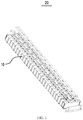
- an embodiment of the present disclosure provides a battery module 20 including: two or more secondary batteries 10 of this embodiment and a bus bar for connecting two secondary batteries 10.
- Two or more secondary batteries 10 are disposed side by side in the same direction.
- One end of the bus bar is connected and fixed to one of the two secondary batteries 10, and the other end is connected and fixed to the other secondary battery 10.
- the two or more secondary batteries 10 of this embodiment can be disposed side by side along their own thickness direction to form the battery module 20.
- the secondary battery 10 of the embodiment of the present disclosure includes a housing 11, an electrode assembly disposed in the housing 11, and a top cover assembly 12 hermetically connected to the housing 11.
- the housing 11 of this embodiment may be in a shape of a quadrangular prism or other shapes.
- the housing 11 includes a receiving hole 11a with an opening.
- the receiving hole 11a is used to receive the electrode assembly 13 and electrolyte.
- the housing 11 may be made of materials such as aluminum, aluminum alloy, or plastic.
- the electrode assembly 13 of the embodiment of the present disclosure includes two end faces 13a opposite to each other in a first direction Y perpendicular to an axial direction X of the receiving hole 11a, and a pole tab 13b extending from each end face 13a.
- the axial direction X and an extending direction of the receiving hole 11a are the same.
- one pole tab 13b extends from each end face 13a of the electrode assembly 13.
- Each electrode assembly 13 includes two pole tabs 13b opposite to each other along the first direction Y.
- One pole tab 13b is used as a positive pole tab and the other is used as a negative pole tab.
- the electrode assembly 13 of this embodiment includes two or more electrode units 131 stacked along the axial direction X of the receiving hole 11a.
- the electrode unit 131 includes a sub-end face 131a and a sub-pole tab 131b extending from the sub-end face 131a.
- a body of the electrode unit 131 and a sub-pole tab 131b connected to the body this embodiment can be formed by a stacking or winding of a first pole piece, a second pole piece, and an insulating film together.
- the insulating film is provided as an insulator between the first pole piece and the second pole piece.
- the electrode unit 131 of this embodiment includes one insulating film, one first pole piece, one insulating film and one second pole piece.
- the first pole piece is exemplarily described as a positive pole piece and the second pole piece is a negative pole piece.
- the first pole piece may also be a negative pole piece
- the second pole piece is a positive pole piece.
- positive electrode active material is coated on a coating area of the positive pole piece
- negative electrode active material is coated on a coating area of the negative pole piece.
- Multiple uncoated areas extending from the main body serve as the sub-pole tabs 131b.
- Each electrode unit 131 includes two sub-pole tabs 131b arranged opposite to each other along the first direction Y, namely, a positive pole tab and a negative pole tab.
- the positive pole tab extends from the coating area of the positive pole piece; the negative pole tab extends from the coating area of the negative pole piece.
- the first direction Y is perpendicular to the axial direction X.
- the term "perpendicular to" here is not limited to a strict perpendicular definition in a mathematical sense.
- the end face 13a of each electrode assembly 13 includes the sub-end face 131a of each electrode unit 131, that is, all the sub-end faces 131a of all the electrode units 131 collectively form the end face 13a.
- the pole tab 13b of each electrode assembly 13 includes the sub-pole tabs 131b of each electrode unit 131, that is, all the sub-pole tabs 131b of all the electrode units 131 together form the pole tab 13b.
- the electrode unit 131 is a flat structure with two wide surfaces 131c and two narrow surfaces 131d connecting the two wide surfaces 131c.
- the two wide surfaces 131c are arranged opposite to each other along the axial direction X.
- One wide surface 131c and one narrow surface 131d are alternately arranged.
- the top cover assembly 12 of this embodiment is connected to the housing 11 in a hermetical manner to cover the opening.
- the top cover assembly 12 includes a top cover plate 121 and a pole post 122.
- the top cover assembly 12 is hermetically connected to the housing 11 via the top cover plate 121.
- the pole post 122 is disposed on the top cover plate 121 and is electrically connected to the electrode assembly 13 through the current collector 14.
- a size L of the pole tab 13b is smaller than a size D of the end face 13a. That is, in the second direction of Z, the pole tab 13b of this embodiment is narrower than the end face 13a.
- the current collector 14 of this embodiment includes a main body 141, at least part of which is located between the end face 13a and a side wall of the housing 11, and the main body 141 extends in the axial direction X and is electrically connected with the pole tab 13b. In the second direction Z, the main body 141 and the pole tab 13b are at least partially overlapped.
- the size of the pole tab 13b in the second direction Z in this embodiment is smaller than the size of the end face 13a in the second direction Z, a larger avoidance space can be reserved in the second direction Z. Therefore, at least a part of the main body 141 of the embodiment is disposed in the avoidance space and overlaps with the pole tab 13b in the second direction Z, so that the main body 141 does not occupy too much space formed between the end face 13a of the electrode assembly 13 and the housing 11 in the first direction Y, which is beneficial to increasing energy density of the secondary battery 10.
- the pole tab 13b of this embodiment is smaller than the size D of the end face 13a, the pole tab is easily to be bent and can give way sufficient space for the main body 141 in the second direction Z.
- the end face 13a in the second direction Z, includes a first area 130a and a second area 130b.
- the pole tab 13b extends from the first area 130a.
- the second area 130b is located on one side of the first area 130a.
- a portion of the main body 141 located between the end face 13a and the housing 11 is opposite to the second area 130b.
- a sum of a size H of the main body 141 and the pole tab 13b is smaller than the size D of the end face 13a (see FIG. 2 ), so as to ensure that the current collector 14 as a whole will not go beyond an edge of the electrode unit 131 in the second direction Z, so as to reduce the space occupied by the current collector 14 in the second direction Z and effectively improve the energy density of the secondary battery 10.
- the end face 13a further includes a third area 130c.
- the third area 130c is located on the other side of the first area 130a. That is, the third area 130c and the second area 130b are respectively located on two sides of the first area 130a, so that the pole tab 13b extending from the first area 130a in this embodiment is a die-cut pole tab and its cross section is approximately rectangular or approximately trapezoidal. Therefore, compared to the pole tab 13b with the cross section having an arc-shaped area, the pole tab 13b of this embodiment has a good ability to be bent along the axial direction X, and the pole tab 13b will not be broken or torn caused by stress concentration when the arc-shaped area is bent.
- a size of the third area 130c is smaller than a size of the second area 130b, so that a position of the pole tab 13b of the present embodiment is closer to one narrow surface 131d than the other narrow surface 131d, and thus the main body 141 can have a larger size.
- the main body 141 has a plate-shaped structure.
- the pole tab 13b can be folded along the first direction Y and connected to a surface of the main body 141 facing away from the electrode unit 131, so that the pole tab 13b can be directly connected to the main body 141.
- the pole tab 13b can be folded along the second direction Z and connected to the main body 141, or can be folded along the axial direction X and connected to the main body 141.
- the current collector 14 of this embodiment further includes a current collecting sheet 14a.
- the current collecting sheet 14a is connected to the main body 141.
- the pole tab 13b is connected to the main body 141 via the current collecting sheet 14a.
- the current collecting sheet 14a is used to be connected and fixed with the pole tab 13b, and both are located on the same side of the main body 141 along the second direction Z, so that a part of the current collecting sheet 14a and the pole tab 13b are overlapped in the axial direction X, effectively reducing space occupied by the current collecting sheet 14a in the second direction Z, which is beneficial to increasing the energy density of the secondary battery 10 and improve the flow capacity of the current collecting sheet 14a at the same time.
- the current collecting sheet 14a is disposed on the main body 141 of the current collector 14, which facilitates a welding connection of the pole tab 13b and the current collecting sheet 14a via welding equipment, and reduces welding difficulty.
- the current collecting sheet 14a and the pole tab 13b are welded and connected by means of ultrasonic welding.
- the current collecting sheet 14a of this embodiment is a sheet-like structure with a predetermined thickness.
- the thickness direction of the current collecting sheet 14a is parallel to the axial direction X.
- the current collecting sheet 14a extends from the main body 141 toward the housing 11.
- the pole tab 13b can be connected to a surface of the current collecting sheet 14a facing the top cover assembly 12.
- the surface of the current collecting sheet 14a facing the top cover assembly 12 and a surface of the pole tab 13b facing the current collecting sheet 14a are basically in the same plane, so that the pole tab 13b can be connected and fixed with the current collecting sheet 14a without bending, and the possibility of breaking or tearing due to bending of the pole tab 13b itself is lowered.
- the thickness direction of the current collecting sheet 14a is parallel to the first direction Y.
- Two opposite surfaces of the current collecting sheet 14a along the first direction Y have a relatively large area, and both can be connected and fixed with the pole tab 13b.
- the pole tab 13b is bent in the first direction Y, and is connected and fixed with the surface of the current collecting sheet 14a facing away from the end face 13a, so that the current collecting sheet 14a protects the electrode assembly 13 and a free end of the pole tab 13b will not be folded during installation or later use to contact the end face 13a of the electrode assembly 13, thereby reducing a possibility that the pole tab 13b is folded and inserted into the end face 13a to cause structural damage or breakage of the electrode unit 131.
- the current collecting sheet 14a can be welded and connected to the pole tab 13b with its thickness direction parallel to the axial direction X.
- the current collecting sheet 14a is bent in the first direction Y, and the thickness direction of the current collecting sheet 14a and the first direction Y are made to be parallel. In this way, the size of the current collecting sheet 14a in the thickness direction is small, so that space formed between the electrode assembly 13 and the housing 11 occupied by the current collector is less, and the energy density of the secondary battery 10 is effectively improved.
- the current collecting sheet 14a can be directly connected to the main body 141.
- the pole tab 13b is connected to the main body 141 via the current collecting sheet 14a.
- the current collecting sheet 14a of this embodiment intersects the main body 141.
- the main body 141 is a strip structure extending in the axial direction X, and the current collecting sheet 14a extends in the second direction Z and is perpendicular to the main body 141.
- the pole tab 13b can be connected to the surface of the current collecting sheet 14a facing the top cover assembly 12 or facing away from the top cover assembly 12.
- the current collector 14 further includes a transition portion 142.
- the transition portion 142 extends in the second direction Z and towards an outside of the main body 141.
- the current collecting sheet 14a is connected to an edge of the transition portion 142 in the axial direction X.
- the main body 141 of the current collector 14 is located on one side of the pole tab 13b in the second direction Z, and the transition portion 142 and the pole tab 13b are at least partially overlapped in the axial direction X.
- the current collecting sheet 14a is disposed on an area of the transition portion 142 corresponding to the pole tab 13b.
- the transition portion 142 is used for a transitional connection between the current collecting sheet 14a and the main body 141, which is beneficial to improving the flow capacity between the current collecting sheet 14a and the main body 141.
- the main body 141 and the transition portion 142 have an L-shaped structure.
- a number of electrode assemblies 13 is set as two.
- the two sets of electrode assemblies 13 are stacked in the axial direction X.
- a number of current collecting sheets 14a is set as two.
- the two current collecting sheets 14a are disposed to be spaced apart along the axial direction X.
- the pole tabs 13b of one set of electrode assembly 13 and the pole tabs 13b of the other set of electrode assembly 13 are respectively connected to both current collecting sheets 14a.
- two current collecting sheets 14a are used to connect the pole tabs 13b with the same polarity of the two sets of electrode assemblies 13 to realize current collection.
- the pole tab 13b extends to a short distance to be connected and fixed with the first current collecting sheet 14a or the second current collecting sheet 14a at a corresponding position, so that there is no need for the pole tab 13b to extend too long out of the end face 13a to be connected to the first current collecting sheet 14a. Therefore, the electrode unit 131 has a uniform processing size and a uniform processing procedure, thereby reducing processing and manufacturing difficulties and processing costs.
- each electrode assembly 13 includes two electrode units 131.
- the electrode unit 131 has a sub-end face 131a and a sub-pole tab 131b extending from the sub-end face 131a.
- two sub-end faces 131a on the same side form the end face 13a of the electrode assembly 13.
- Two sub-tabs 131b with the same polarity converge to form the pole tab 13b of one electrode assembly 13.
- the sub-pole tab 131b of one electrode unit 131 extends from an area of the sub-end face 131a close to the other electrode unit 131 in the axial direction X, so that the respective sub-pole tabs 131b of the two electrode units 131 are close to each other and extend a short distance to converge to form the pole tab 13b to be connected and fixed with the current collector 14a.
- the sub-pole tab 131b will not have length redundancy due to an excessive extension of itself.
- the sub-pole tab 131b has the length redundancy, it is easy to cause a stress concentration area and thus a breakage of the sub-pole tab 131b when it is bent.
- the extension size of the sub-pole tab 131b is controlled within a small range, which is beneficial to reducing space occupancy rate of the pole tab 13b formed by converge of the sub-pole tabs 131b and improve the energy density of the secondary battery 10.
- the pole tab 13b of one set of electrode assembly 13 and the pole tab 13b of the other set of electrode assembly 13 are at least partially overlapped along the axial direction X.
- the space occupancy rate of the respective current collecting sheets 14a in the second direction Z can be reduced, which is beneficial to reducing the overall size and weight of the current collecting sheet and thereby beneficial to increasing the energy density of the secondary battery.
- the two pole tabs 13b are completely overlapped in the axial direction X, that is, the two pole tabs 13b are aligned in the axial direction X.
- the current collecting sheets 14a respectively connected to the two pole tabs 13b are also aligned in the axial direction X, so the space occupation rate of the current collecting sheet 14a in the second direction Z is minimized.
- the electrode unit 131 of this embodiment has two wide surfaces 131c and two narrow surfaces 131d connecting the two wide surfaces 131c.
- the two wide surfaces 131c are disposed opposite to each other along the axial direction X.
- One wide surface 131c and one narrow surface 131d are alternately disposed.
- the pole tab 13b extends from an area of the end face 13a close to two adjacent wide surfaces 131c of the two electrode units 131, so that the pole tab 13b is approximately in the central area of the end face 13a in the axial direction X, ensuring that the sizes of the two sub-pole tabs 131b leading out of the two electrode units 131 are approximately the same, which is beneficial to consistency of the processing and manufacturing process of the electrode unit 131 and reduces the processing and manufacturing cost.
- a ratio of the size of the pole tab 13b to the size of the end face 13a is 1/10 to 2/5 in the second direction Z.
- the battery module 20 of the embodiment of the present disclosure includes a plurality of secondary batteries 10 arranged side by side in the same direction.
- the electrode units 131 included in each secondary battery 10 of this embodiment are stacked along the axial direction X of the receiving hole 11a of the housing 11, when the electrode unit 131 of this embodiment expands, it expands and deforms mainly along the axial direction X of the receiving hole 11a, and an amount of expansion in an arrangement direction of the secondary batteries 10 is small. In this way, a total expansion force accumulated in the arrangement direction of all the secondary batteries 10 is small.
- the battery module 20 does not need to use higher-strength structural members to restrain and offset the expansion force, or use lower-strength structural members to restrain and offset the expansion force, thereby effectively reducing an overall weight of the battery module 20, making structure of the battery module 20 more compact, and effectively improving the energy density of the battery module 20.
- the battery module 20 itself has little or no expansion in the thickness direction of the secondary battery 10 itself, which can effectively improve safety during use process.
Landscapes
- Chemical & Material Sciences (AREA)
- Chemical Kinetics & Catalysis (AREA)
- Electrochemistry (AREA)
- General Chemical & Material Sciences (AREA)
- Engineering & Computer Science (AREA)
- Manufacturing & Machinery (AREA)
- Connection Of Batteries Or Terminals (AREA)
Abstract
Description
- The present disclosure claims priority to
Chinese patent application No. 201811646824.0 - The present disclosure relates to the technical field of battery technology, in particular to a secondary battery and a battery module.
- With development of science and technology, secondary batteries have been widely used in portable electronic devices, such as mobile phones, digital cameras, and laptop computers, and have a wide range of application prospects in electric transports, such as electric vehicles and electric bicycles, and energy storage facilities and other large and medium-sized electric equipment. It has become an important technical means to solve global problems, such as energy crisis and environmental pollution. In the prior art, a secondary battery includes a housing, an electrode assembly disposed in the housing, and a current collector connected with the electrode assembly. The electrode assembly has a flat body and a pole tab extending from the body. In the prior art, the current collector can be disposed at an end of the pole tab and fixedly connected with the end of the tab. However, the current collector itself occupies space between the pole tabs and the housing, which makes a size of the secondary battery larger and affects an energy density of the secondary battery.
- Embodiments of the present disclosure provide a secondary battery and a battery module. A main body of a current collector and pole tabs in the secondary battery are disposed side by side, thereby reducing an occupancy rate of space between an electrode unit and a housing, which is beneficial to increasing an energy density.
- In an aspect, an embodiment of the present disclosure provides a secondary battery, comprising:
a housing comprising a receiving hole with an opening; a top cover assembly hermetically connected with the housing to close the opening; an electrode assembly disposed in the receiving hole, and comprising two end faces opposite to each other in a first direction perpendicular to an axial direction of the receiving hole and a pole tab extending from one of the end faces, wherein the electrode assembly comprises two or more electrode units stacked along the axial direction, and a size of the pole tab is smaller than a size of each of the end faces along a second direction perpendicular to the axial direction and the first direction; a current collector comprising a main body at least partially located between one of the end faces and the housing, wherein the main body extends along the axial direction and is electrically connected with the pole tab, and the main body and the pole tab are at least partially overlapped along the second direction. - The secondary battery provided according to an embodiment of the present disclosure includes the housing, the electrode assembly disposed in the housing, and the top cover assembly hermetically connected with the housing. The electrode assembly has two opposite end faces in the first direction and the pole tab extending from each of the end faces. Since in this embodiment, the size of the pole tab in the second direction is smaller than the size of each of the end faces along the second direction. That is, in the second direction, the pole tab is narrower than the end faces, the pole tab can give way to more avoidance space in the second direction, so that the main body included in the current collector and the pole tab of this embodiment can be disposed side by side in the second direction. And the main body and the pole tab are at least partially overlapped in the second direction. Since the main body and the pole tab are disposed side by side in the second direction, space occupied by the main body in the first direction is significantly reduced, which is beneficial to increasing energy density of the secondary battery.
- In another aspect, an embodiment of the present disclosure provides a battery module comprising two or more secondary batteries according to the above embodiment, and the two or more secondary batteries are disposed side by side.
- Below, features, advantages, and technical effects of an exemplary embodiment of the present disclosure will be described with reference to the drawings.
-
FIG. 1 is a schematic structural diagram of a battery module according to an embodiment of the present disclosure; -
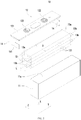
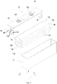
FIG. 2 is a schematic exploded structural diagram of a secondary battery according to an embodiment of the present disclosure; -
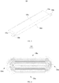
FIG. 3 is a schematic structural diagram of an electrode unit according to an embodiment of the present disclosure; -
FIG. 4 is a schematic cross-sectional structural diagram of an electrode unit according to an embodiment of the present disclosure; -
FIG. 5 is a schematic structural side view of an electrode assembly according to an embodiment of the present disclosure; -
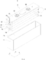
FIG. 6 is a schematic exploded structural diagram of a secondary battery according to another embodiment of the present disclosure; -
FIG. 7 is a schematic exploded structural diagram of a secondary battery according to another embodiment of the present disclosure; -
FIG. 8 is a schematic diagram of a connection structure of a current collector and an electrode assembly of the secondary battery in the embodiment ofFIG. 7 ; -
FIG. 9 is a schematic exploded structural diagram of a secondary battery according to still another embodiment of the present disclosure; -
FIG. 10 is a schematic diagram of a connection structure of a current collector and an electrode assembly of the secondary battery in the embodiment ofFIG. 9 . - In the drawings, the drawings are not drawn to scale.
- 10. secondary battery; 11, housing; 11a, receiving hole; 12, top cover assembly; 121, top cover plate; 122, pole post; 13, electrode assembly; 13a, end face; 130a, first area; 130b, second area; 130c, third area; 13b, pole tab; 131, electrode unit; 131a, sub-end face; 131b, sub-pole tab; 131c, wide surface; 131d, narrow surface; 14, current collector; 14a, current collecting sheet; 141, main body; 142, transition portion; X, axial direction; Y, first direction; Z, second direction; 20, battery module.
- Below, embodiments of the present disclosure will be further described in detail with reference to accompanying drawings and embodiments. The detailed description of the embodiments and the accompanying drawings are intended to illustrate the principles of the present disclosure and are not intended to limit the scope of the present disclosure.
- In the description of the present disclosure, it should be noted that, unless otherwise stated, the meaning of "a plurality" and the like is two or more; the orientation or positional relationship indicated by the terms "upper", "lower", "left", "right", "inside", "outside" and the like is merely for the purpose of describing the present disclosure and simplifying the description, and is not intended to indicate or imply that the device or component referred to has a particular orientation, is constructed and operated in a particular orientation, and therefore cannot be understood to be a limitation of the present disclosure. Moreover, the terms "first", "second", "third" and the like are used for descriptive purposes only and are not to be construed as indicating or implying relative importance.
- In the description of the present disclosure, it should be noted that, unless otherwise stated, the terms "installation", "connected to", and "connected with" are to be understood broadly, and may be, for example, a fixed connection, a detachable connection, or an integral connection; they can be connected directly or indirectly through an intermediate medium. The specific meaning of the above terms in the present disclosure can be understood by those skilled in the art according to actual circumstance.
- In order to better understand the present disclosure, a
battery module 20 and asecondary battery 10 according to embodiments of the present disclosure will be described in detail below with reference toFIGS. 1 to 10 . - As shown in
FIG. 1 , an embodiment of the present disclosure provides abattery module 20 including: two or moresecondary batteries 10 of this embodiment and a bus bar for connecting twosecondary batteries 10. Two or moresecondary batteries 10 are disposed side by side in the same direction. One end of the bus bar is connected and fixed to one of the twosecondary batteries 10, and the other end is connected and fixed to the othersecondary battery 10. The two or moresecondary batteries 10 of this embodiment can be disposed side by side along their own thickness direction to form thebattery module 20. - Referring to
FIG. 2 , thesecondary battery 10 of the embodiment of the present disclosure includes ahousing 11, an electrode assembly disposed in thehousing 11, and atop cover assembly 12 hermetically connected to thehousing 11. - The
housing 11 of this embodiment may be in a shape of a quadrangular prism or other shapes. Thehousing 11 includes areceiving hole 11a with an opening. The receivinghole 11a is used to receive theelectrode assembly 13 and electrolyte. Thehousing 11 may be made of materials such as aluminum, aluminum alloy, or plastic. - The
electrode assembly 13 of the embodiment of the present disclosure includes twoend faces 13a opposite to each other in a first direction Y perpendicular to an axial direction X of thereceiving hole 11a, and apole tab 13b extending from eachend face 13a. The axial direction X and an extending direction of thereceiving hole 11a are the same. In this embodiment, onepole tab 13b extends from eachend face 13a of theelectrode assembly 13. Eachelectrode assembly 13 includes twopole tabs 13b opposite to each other along the first direction Y. Onepole tab 13b is used as a positive pole tab and the other is used as a negative pole tab. - Referring to
FIGS. 3 and 4 , theelectrode assembly 13 of this embodiment includes two ormore electrode units 131 stacked along the axial direction X of thereceiving hole 11a. Theelectrode unit 131 includes asub-end face 131a and asub-pole tab 131b extending from thesub-end face 131a. A body of theelectrode unit 131 and asub-pole tab 131b connected to the body this embodiment can be formed by a stacking or winding of a first pole piece, a second pole piece, and an insulating film together. The insulating film is provided as an insulator between the first pole piece and the second pole piece. Theelectrode unit 131 of this embodiment includes one insulating film, one first pole piece, one insulating film and one second pole piece. In this embodiment, the first pole piece is exemplarily described as a positive pole piece and the second pole piece is a negative pole piece. Similarly, in other embodiments, the first pole piece may also be a negative pole piece, and the second pole piece is a positive pole piece. In addition, positive electrode active material is coated on a coating area of the positive pole piece, and negative electrode active material is coated on a coating area of the negative pole piece. Multiple uncoated areas extending from the main body serve as thesub-pole tabs 131b. Eachelectrode unit 131 includes twosub-pole tabs 131b arranged opposite to each other along the first direction Y, namely, a positive pole tab and a negative pole tab. The positive pole tab extends from the coating area of the positive pole piece; the negative pole tab extends from the coating area of the negative pole piece. The first direction Y is perpendicular to the axial direction X. The term "perpendicular to" here is not limited to a strict perpendicular definition in a mathematical sense. Theend face 13a of eachelectrode assembly 13 includes thesub-end face 131a of eachelectrode unit 131, that is, all the sub-end faces 131a of all theelectrode units 131 collectively form theend face 13a. Thepole tab 13b of eachelectrode assembly 13 includes thesub-pole tabs 131b of eachelectrode unit 131, that is, all thesub-pole tabs 131b of all theelectrode units 131 together form thepole tab 13b. In one embodiment, referring toFIG. 4 , theelectrode unit 131 is a flat structure with twowide surfaces 131c and twonarrow surfaces 131d connecting the twowide surfaces 131c. The twowide surfaces 131c are arranged opposite to each other along the axial direction X. Onewide surface 131c and onenarrow surface 131d are alternately arranged. - The
top cover assembly 12 of this embodiment is connected to thehousing 11 in a hermetical manner to cover the opening. In one embodiment, thetop cover assembly 12 includes atop cover plate 121 and apole post 122. Thetop cover assembly 12 is hermetically connected to thehousing 11 via thetop cover plate 121. Thepole post 122 is disposed on thetop cover plate 121 and is electrically connected to theelectrode assembly 13 through thecurrent collector 14. - In the embodiment of the present disclosure, referring to
FIG. 2 , in the second direction Z perpendicular to the axial direction X and the first direction Y, a size L of thepole tab 13b is smaller than a size D of theend face 13a. That is, in the second direction of Z, thepole tab 13b of this embodiment is narrower than theend face 13a. Thecurrent collector 14 of this embodiment includes amain body 141, at least part of which is located between theend face 13a and a side wall of thehousing 11, and themain body 141 extends in the axial direction X and is electrically connected with thepole tab 13b. In the second direction Z, themain body 141 and thepole tab 13b are at least partially overlapped. Since the size of thepole tab 13b in the second direction Z in this embodiment is smaller than the size of theend face 13a in the second direction Z, a larger avoidance space can be reserved in the second direction Z. Therefore, at least a part of themain body 141 of the embodiment is disposed in the avoidance space and overlaps with thepole tab 13b in the second direction Z, so that themain body 141 does not occupy too much space formed between theend face 13a of theelectrode assembly 13 and thehousing 11 in the first direction Y, which is beneficial to increasing energy density of thesecondary battery 10. - Since the size L of the
pole tab 13b of this embodiment is smaller than the size D of theend face 13a, the pole tab is easily to be bent and can give way sufficient space for themain body 141 in the second direction Z. - In one embodiment, referring to
FIG. 5 , in the second direction Z, theend face 13a includes afirst area 130a and asecond area 130b. Thepole tab 13b extends from thefirst area 130a. Thesecond area 130b is located on one side of thefirst area 130a. A portion of themain body 141 located between theend face 13a and thehousing 11 is opposite to thesecond area 130b. Preferably, in this embodiment, as shown inFIG. 8 , in the second direction Z, a sum of a size H of themain body 141 and thepole tab 13b (seeFIG. 8 ) is smaller than the size D of theend face 13a (seeFIG. 2 ), so as to ensure that thecurrent collector 14 as a whole will not go beyond an edge of theelectrode unit 131 in the second direction Z, so as to reduce the space occupied by thecurrent collector 14 in the second direction Z and effectively improve the energy density of thesecondary battery 10. - In an embodiment, in the second direction Z, the
end face 13a further includes athird area 130c. Thethird area 130c is located on the other side of thefirst area 130a. That is, thethird area 130c and thesecond area 130b are respectively located on two sides of thefirst area 130a, so that thepole tab 13b extending from thefirst area 130a in this embodiment is a die-cut pole tab and its cross section is approximately rectangular or approximately trapezoidal. Therefore, compared to thepole tab 13b with the cross section having an arc-shaped area, thepole tab 13b of this embodiment has a good ability to be bent along the axial direction X, and thepole tab 13b will not be broken or torn caused by stress concentration when the arc-shaped area is bent. In addition, a size of thethird area 130c is smaller than a size of thesecond area 130b, so that a position of thepole tab 13b of the present embodiment is closer to onenarrow surface 131d than the othernarrow surface 131d, and thus themain body 141 can have a larger size. In particular, when the size of theelectrode assembly 13 in the second direction Z is relatively small, it is more necessary to ensure the size of themain body 141 in the second direction Z to increase its flow capacity. In one embodiment, themain body 141 has a plate-shaped structure. Thepole tab 13b can be folded along the first direction Y and connected to a surface of themain body 141 facing away from theelectrode unit 131, so that thepole tab 13b can be directly connected to themain body 141. Optionally, thepole tab 13b can be folded along the second direction Z and connected to themain body 141, or can be folded along the axial direction X and connected to themain body 141. - As shown in
FIG. 6 andFIG. 7 , thecurrent collector 14 of this embodiment further includes acurrent collecting sheet 14a. Thecurrent collecting sheet 14a is connected to themain body 141. Thepole tab 13b is connected to themain body 141 via thecurrent collecting sheet 14a. Thecurrent collecting sheet 14a is used to be connected and fixed with thepole tab 13b, and both are located on the same side of themain body 141 along the second direction Z, so that a part of thecurrent collecting sheet 14a and thepole tab 13b are overlapped in the axial direction X, effectively reducing space occupied by thecurrent collecting sheet 14a in the second direction Z, which is beneficial to increasing the energy density of thesecondary battery 10 and improve the flow capacity of thecurrent collecting sheet 14a at the same time. Thecurrent collecting sheet 14a is disposed on themain body 141 of thecurrent collector 14, which facilitates a welding connection of thepole tab 13b and thecurrent collecting sheet 14a via welding equipment, and reduces welding difficulty. Optionally, thecurrent collecting sheet 14a and thepole tab 13b are welded and connected by means of ultrasonic welding. For example, thecurrent collecting sheet 14a of this embodiment is a sheet-like structure with a predetermined thickness. - In an embodiment, referring to
FIGS. 7 and8 , the thickness direction of thecurrent collecting sheet 14a is parallel to the axial direction X. Thecurrent collecting sheet 14a extends from themain body 141 toward thehousing 11. In an example, thepole tab 13b can be connected to a surface of thecurrent collecting sheet 14a facing thetop cover assembly 12. The surface of thecurrent collecting sheet 14a facing thetop cover assembly 12 and a surface of thepole tab 13b facing thecurrent collecting sheet 14a are basically in the same plane, so that thepole tab 13b can be connected and fixed with thecurrent collecting sheet 14a without bending, and the possibility of breaking or tearing due to bending of thepole tab 13b itself is lowered. At the same time, since there is larger space on opposite sides in the axial direction X of thecurrent collecting sheet 14a, it is convenient to use welding equipment to clamp thecurrent collecting sheet 14a from opposite sides of thecurrent collecting sheet 14a and weld and connect thepole tab 13b and thecurrent collecting sheet 14a, which effectively reduces operation difficulty during the welding and connection process. - In another embodiment, referring to
FIGS. 9 and10 , the thickness direction of thecurrent collecting sheet 14a is parallel to the first direction Y. Two opposite surfaces of thecurrent collecting sheet 14a along the first direction Y have a relatively large area, and both can be connected and fixed with thepole tab 13b. In one example, thepole tab 13b is bent in the first direction Y, and is connected and fixed with the surface of thecurrent collecting sheet 14a facing away from theend face 13a, so that thecurrent collecting sheet 14a protects theelectrode assembly 13 and a free end of thepole tab 13b will not be folded during installation or later use to contact theend face 13a of theelectrode assembly 13, thereby reducing a possibility that thepole tab 13b is folded and inserted into theend face 13a to cause structural damage or breakage of theelectrode unit 131. Thecurrent collecting sheet 14a can be welded and connected to thepole tab 13b with its thickness direction parallel to the axial direction X. Then thecurrent collecting sheet 14a is bent in the first direction Y, and the thickness direction of thecurrent collecting sheet 14a and the first direction Y are made to be parallel. In this way, the size of thecurrent collecting sheet 14a in the thickness direction is small, so that space formed between theelectrode assembly 13 and thehousing 11 occupied by the current collector is less, and the energy density of thesecondary battery 10 is effectively improved. - In one embodiment, referring to
FIG. 6 , thecurrent collecting sheet 14a can be directly connected to themain body 141. Thepole tab 13b is connected to themain body 141 via thecurrent collecting sheet 14a. Thecurrent collecting sheet 14a of this embodiment intersects themain body 141. Preferably, themain body 141 is a strip structure extending in the axial direction X, and thecurrent collecting sheet 14a extends in the second direction Z and is perpendicular to themain body 141. Thepole tab 13b can be connected to the surface of thecurrent collecting sheet 14a facing thetop cover assembly 12 or facing away from thetop cover assembly 12. - In one embodiment, referring to
FIG. 7 orFIG. 9 , thecurrent collector 14 further includes atransition portion 142. Thetransition portion 142 extends in the second direction Z and towards an outside of themain body 141. Thecurrent collecting sheet 14a is connected to an edge of thetransition portion 142 in the axial direction X. Themain body 141 of thecurrent collector 14 is located on one side of thepole tab 13b in the second direction Z, and thetransition portion 142 and thepole tab 13b are at least partially overlapped in the axial direction X. Thecurrent collecting sheet 14a is disposed on an area of thetransition portion 142 corresponding to thepole tab 13b. Thetransition portion 142 is used for a transitional connection between thecurrent collecting sheet 14a and themain body 141, which is beneficial to improving the flow capacity between thecurrent collecting sheet 14a and themain body 141. In one embodiment, themain body 141 and thetransition portion 142 have an L-shaped structure. - In one embodiment, a number of
electrode assemblies 13 is set as two. The two sets ofelectrode assemblies 13 are stacked in the axial direction X. A number ofcurrent collecting sheets 14a is set as two. The twocurrent collecting sheets 14a are disposed to be spaced apart along the axial direction X. Thepole tabs 13b of one set ofelectrode assembly 13 and thepole tabs 13b of the other set ofelectrode assembly 13 are respectively connected to bothcurrent collecting sheets 14a. In this embodiment, twocurrent collecting sheets 14a are used to connect thepole tabs 13b with the same polarity of the two sets ofelectrode assemblies 13 to realize current collection. In this way, on one hand, temperature at a connecting position of thepole tab 13b and a firstcurrent collecting sheet 14a can be avoided to be too high whenmultiple electrode units 131 are connected to the firstcurrent collecting sheet 14a via onepole tab 13b, and occurrence of faulty welding is avoided to a certain extent. On the other hand, thepole tab 13b extends to a short distance to be connected and fixed with the firstcurrent collecting sheet 14a or the secondcurrent collecting sheet 14a at a corresponding position, so that there is no need for thepole tab 13b to extend too long out of theend face 13a to be connected to the firstcurrent collecting sheet 14a. Therefore, theelectrode unit 131 has a uniform processing size and a uniform processing procedure, thereby reducing processing and manufacturing difficulties and processing costs. Optionally, the two sets ofelectrode assemblies 13 are stacked in the axial direction X. Eachelectrode assembly 13 includes twoelectrode units 131. Theelectrode unit 131 has asub-end face 131a and asub-pole tab 131b extending from thesub-end face 131a. In the first direction Y, twosub-end faces 131a on the same side form theend face 13a of theelectrode assembly 13. Two sub-tabs 131b with the same polarity converge to form thepole tab 13b of oneelectrode assembly 13. Thesub-pole tab 131b of oneelectrode unit 131 extends from an area of thesub-end face 131a close to theother electrode unit 131 in the axial direction X, so that the respectivesub-pole tabs 131b of the twoelectrode units 131 are close to each other and extend a short distance to converge to form thepole tab 13b to be connected and fixed with thecurrent collector 14a. In this way, on one hand, thesub-pole tab 131b will not have length redundancy due to an excessive extension of itself. When thesub-pole tab 131b has the length redundancy, it is easy to cause a stress concentration area and thus a breakage of thesub-pole tab 131b when it is bent. On the other hand, the extension size of thesub-pole tab 131b is controlled within a small range, which is beneficial to reducing space occupancy rate of thepole tab 13b formed by converge of thesub-pole tabs 131b and improve the energy density of thesecondary battery 10. - In one embodiment, the
pole tab 13b of one set ofelectrode assembly 13 and thepole tab 13b of the other set ofelectrode assembly 13 are at least partially overlapped along the axial direction X. When the twopole tabs 13b are at least partially overlapped in the axial direction X, the space occupancy rate of the respectivecurrent collecting sheets 14a in the second direction Z can be reduced, which is beneficial to reducing the overall size and weight of the current collecting sheet and thereby beneficial to increasing the energy density of the secondary battery. Preferably, the twopole tabs 13b are completely overlapped in the axial direction X, that is, the twopole tabs 13b are aligned in the axial direction X. Thecurrent collecting sheets 14a respectively connected to the twopole tabs 13b are also aligned in the axial direction X, so the space occupation rate of thecurrent collecting sheet 14a in the second direction Z is minimized. - The
electrode unit 131 of this embodiment has twowide surfaces 131c and twonarrow surfaces 131d connecting the twowide surfaces 131c. The twowide surfaces 131c are disposed opposite to each other along the axial direction X. Onewide surface 131c and onenarrow surface 131d are alternately disposed. Thepole tab 13b extends from an area of theend face 13a close to two adjacentwide surfaces 131c of the twoelectrode units 131, so that thepole tab 13b is approximately in the central area of theend face 13a in the axial direction X, ensuring that the sizes of the twosub-pole tabs 131b leading out of the twoelectrode units 131 are approximately the same, which is beneficial to consistency of the processing and manufacturing process of theelectrode unit 131 and reduces the processing and manufacturing cost. In one embodiment, a ratio of the size of thepole tab 13b to the size of theend face 13a is 1/10 to 2/5 in the second direction Z. - The
battery module 20 of the embodiment of the present disclosure includes a plurality ofsecondary batteries 10 arranged side by side in the same direction. As theelectrode units 131 included in eachsecondary battery 10 of this embodiment are stacked along the axial direction X of the receivinghole 11a of thehousing 11, when theelectrode unit 131 of this embodiment expands, it expands and deforms mainly along the axial direction X of the receivinghole 11a, and an amount of expansion in an arrangement direction of thesecondary batteries 10 is small. In this way, a total expansion force accumulated in the arrangement direction of all thesecondary batteries 10 is small. In the arrangement direction of thesecondary batteries 10, thebattery module 20 does not need to use higher-strength structural members to restrain and offset the expansion force, or use lower-strength structural members to restrain and offset the expansion force, thereby effectively reducing an overall weight of thebattery module 20, making structure of thebattery module 20 more compact, and effectively improving the energy density of thebattery module 20. Moreover, thebattery module 20 itself has little or no expansion in the thickness direction of thesecondary battery 10 itself, which can effectively improve safety during use process. - Although the present disclosure has been described with reference to preferred embodiments, various modifications can be made thereto and the components therein can be replaced with equivalents without departing from the scope of the present disclosure, especially as long as there is no structural conflict, the technical features mentioned in the embodiments can be combined in any way. The present disclosure is not limited to the specific embodiments disclosed herein, but includes all technical solutions falling within the scope of the claims.
Claims (13)
- A secondary battery, comprising:a housing comprising a receiving hole with an opening;a top cover assembly hermetically connected with the housing to close the opening;an electrode assembly disposed in the receiving hole, and comprising two end faces opposite to each other in a first direction perpendicular to an axial direction of the receiving hole and a pole tab extending from one of the end faces, wherein the electrode assembly comprises two or more electrode units stacked along the axial direction, and a size of the pole tab is smaller than a size of each of the end faces along a second direction perpendicular to the axial direction and the first direction;a current collector comprising a main body at least partially located between one of the end faces and the housing, wherein the main body extends along the axial direction and is electrically connected with the pole tab, and the main body and the pole tab are at least partially overlapped along the second direction.
- The secondary battery according to claim 1, wherein each of the end faces comprises a first area and a second area located on one side of the first area in the second direction, the pole tab extends from the first area, and a portion of the main body between one of the end faces and the housing is disposed to correspond to the second area.
- The secondary battery according to claim 2, wherein a sum of a size of the main body and the size of the pole tab is smaller than the size of each of the end faces in the second direction.
- The secondary battery according to claim 2, wherein each of the end faces further comprises a third area located on the other side of the first area in the second direction, and a size of the third area is smaller than a size of the second area.
- The secondary battery according to claim 1, wherein the current collector further comprises a current collecting sheet used to be connected and fixed with the pole tab, and both the current collecting sheet and the pole tab are located on the same side of the main body in the second direction.
- The secondary battery according to claim 5, wherein a thickness direction of the current collecting sheet is parallel to the axial direction.
- The secondary battery according to claim 6, wherein the current collector further comprises a transition portion extending in the second direction and towards an outside of the main body, and the current collecting sheet is connected to an edge of the transition portion along the axial direction.
- The secondary battery according to claim 5, wherein a thickness direction of the current collecting sheet is parallel to the first direction.
- The secondary battery according to claim 8, wherein the pole tab is bent in the first direction, and is connected and fixed with a surface of the current collecting sheet facing away from the end face.
- The secondary battery according to claim 5, wherein a number of the electrode assemblies is set as two, the two sets of the electrode assemblies are stacked along the axial direction, a number of the current collecting sheets is set as two, the two current collecting sheets are disposed to be spaced apart along the axial direction, the pole tab of one set of the electrode assembly and the pole tab of the other set of the electrode assembly are respectively connected with the two current collecting sheets, and the pole tab of the one set of the electrode assembly and the pole tab of the other set of the electrode assembly are at least partially overlapped in the axial direction.
- The secondary battery according to claim 10, wherein each set of the electrode assembly comprises two electrode units that each comprises a sub-end face and a sub-pole tab extending from the sub-end face, two sub-end faces on the same side form one of the end faces, two sub-pole tabs with the same polarity converge to form the pole tab, and the sub-pole tab of one electrode unit extends out of an area of the sub-end face close to the other electrode unit in the axial direction.
- The secondary battery according to claim 11, wherein each of the electrode units comprises two wide surfaces and two narrow surfaces connecting the two wide surfaces, the two wide surfaces are opposed to each other in the axial direction, one of the wide surfaces and one of the narrow surfaces are alternately disposed; the pole tab extends out of an area of one of the end faces close to adjacent two wide surfaces of the two electrode units.
- A battery module comprising two or more secondary batteries according to any one of claims 1 to 12, and the two or more secondary batteries are disposed side by side.
Applications Claiming Priority (2)
| Application Number | Priority Date | Filing Date | Title |
|---|---|---|---|
| CN201811646824.0A CN111384353B (en) | 2018-12-29 | 2018-12-29 | Secondary battery and battery module |
| PCT/CN2019/076281 WO2020133675A1 (en) | 2018-12-29 | 2019-02-27 | Secondary battery and battery module |
Publications (3)
| Publication Number | Publication Date |
|---|---|
| EP3872893A1 true EP3872893A1 (en) | 2021-09-01 |
| EP3872893A4 EP3872893A4 (en) | 2022-04-20 |
| EP3872893B1 EP3872893B1 (en) | 2023-01-18 |
Family
ID=71128925
Family Applications (1)
| Application Number | Title | Priority Date | Filing Date |
|---|---|---|---|
| EP19905886.8A Active EP3872893B1 (en) | 2018-12-29 | 2019-02-27 | Secondary battery and battery module |
Country Status (5)
| Country | Link |
|---|---|
| US (1) | US11881588B2 (en) |
| EP (1) | EP3872893B1 (en) |
| CN (1) | CN111384353B (en) |
| HU (1) | HUE061209T2 (en) |
| WO (1) | WO2020133675A1 (en) |
Families Citing this family (6)
| Publication number | Priority date | Publication date | Assignee | Title |
|---|---|---|---|---|
| CN111463367B (en) * | 2019-01-22 | 2024-09-06 | 宁德时代新能源科技股份有限公司 | Secondary battery and battery module |
| CN112038650B (en) * | 2020-07-28 | 2025-01-03 | 天津力神聚元新能源科技有限公司 | A soft-packaged lithium carbon fluoride primary battery |
| CN115347327A (en) * | 2021-05-14 | 2022-11-15 | 中创新航科技股份有限公司 | Battery pack and battery pack grouping method |
| CN114122635B (en) * | 2021-07-06 | 2024-06-07 | 江苏时代新能源科技有限公司 | Battery cell, battery, electric equipment and manufacturing method and equipment of battery cell |
| CN119275448A (en) * | 2022-01-14 | 2025-01-07 | 宁德时代新能源科技股份有限公司 | Battery cell and manufacturing method and system thereof, battery and electric device |
| CN115395164B (en) * | 2022-09-16 | 2023-09-15 | 新疆赛创新能源有限公司 | Single battery, battery pack and battery pack |
Family Cites Families (17)
| Publication number | Priority date | Publication date | Assignee | Title |
|---|---|---|---|---|
| KR101125592B1 (en) * | 2007-02-08 | 2012-03-19 | 주식회사 엘지화학 | High Capacity Battery Cell of High Life Characteristics and Safety |
| KR101093696B1 (en) * | 2009-12-01 | 2011-12-15 | 삼성에스디아이 주식회사 | Secondary battery |
| US8617738B2 (en) * | 2010-05-19 | 2013-12-31 | Samsung Sdi Co., Ltd. | Secondary battery |
| KR101233573B1 (en) * | 2011-01-27 | 2013-02-14 | 로베르트 보쉬 게엠베하 | Secondary battery |
| JP2014139883A (en) * | 2013-01-21 | 2014-07-31 | Toyota Industries Corp | Electric storage device, secondary battery, storage module, secondary battery module, and method for manufacturing electric storage device |
| KR20140137180A (en) * | 2013-05-22 | 2014-12-02 | 삼성에스디아이 주식회사 | Rechargeable battery |
| KR20150032086A (en) * | 2013-09-17 | 2015-03-25 | 삼성에스디아이 주식회사 | Rechargeable battery having safty member |
| JP2017059509A (en) * | 2015-09-18 | 2017-03-23 | リチウム エナジー アンド パワー ゲゼルシャフト ミット ベシュレンクテル ハフッング ウント コンパニー コマンディトゲゼルシャフトLithium Energy and Power GmbH & Co. KG | Electricity storage element |
| CN105609882B (en) * | 2016-03-18 | 2024-06-04 | 东莞烯谷新能源科技有限公司 | Internal multi-core stack energy storage device |
| JP6769137B2 (en) * | 2016-06-30 | 2020-10-14 | 株式会社豊田自動織機 | Power storage device |
| CN206650130U (en) * | 2017-04-28 | 2017-11-17 | 长城汽车股份有限公司 | Battery unit and its electrode assemblie and collector |
| KR102397762B1 (en) * | 2017-06-01 | 2022-05-13 | 삼성에스디아이 주식회사 | Secondary battery having positive electrode terminal-integrated cap plate |
| KR102425218B1 (en) * | 2017-08-31 | 2022-07-26 | 삼성에스디아이 주식회사 | Secondary Battery |
| CN108198989B (en) * | 2018-01-16 | 2021-01-12 | 宁德时代新能源科技股份有限公司 | Connecting member and rechargeable battery |
| CN207800665U (en) * | 2018-02-01 | 2018-08-31 | 宁德时代新能源科技股份有限公司 | The cap assembly and secondary cell of secondary cell |
| CN108428921A (en) * | 2018-02-01 | 2018-08-21 | 宁德时代新能源科技股份有限公司 | Secondary battery |
| CN209217104U (en) * | 2018-12-29 | 2019-08-06 | 宁德时代新能源科技股份有限公司 | Secondary battery and battery module |
-
2018
- 2018-12-29 CN CN201811646824.0A patent/CN111384353B/en active Active
-
2019
- 2019-02-27 HU HUE19905886A patent/HUE061209T2/en unknown
- 2019-02-27 WO PCT/CN2019/076281 patent/WO2020133675A1/en not_active Ceased
- 2019-02-27 EP EP19905886.8A patent/EP3872893B1/en active Active
-
2021
- 2021-06-20 US US17/352,352 patent/US11881588B2/en active Active
Also Published As
| Publication number | Publication date |
|---|---|
| US11881588B2 (en) | 2024-01-23 |
| WO2020133675A1 (en) | 2020-07-02 |
| EP3872893A4 (en) | 2022-04-20 |
| CN111384353A (en) | 2020-07-07 |
| EP3872893B1 (en) | 2023-01-18 |
| CN111384353B (en) | 2024-10-15 |
| HUE061209T2 (en) | 2023-05-28 |
| US20210313661A1 (en) | 2021-10-07 |
Similar Documents
| Publication | Publication Date | Title |
|---|---|---|
| US11881588B2 (en) | Secondary battery and battery module | |
| US11177539B2 (en) | Current collector and secondary battery | |
| EP3800686B1 (en) | Secondary battery and battery module | |
| CN111463367B (en) | Secondary battery and battery module | |
| CN209232866U (en) | Secondary battery and battery module | |
| CN209217105U (en) | Current collectors and secondary batteries | |
| CN209217104U (en) | Secondary battery and battery module | |
| US11335978B2 (en) | Secondary battery and battery module | |
| EP3675238B1 (en) | Secondary battery and battery module | |
| US12489161B2 (en) | Secondary battery and battery module | |
| CN116632427A (en) | Battery | |
| CN209298235U (en) | Secondary battery and battery module | |
| WO2021226756A1 (en) | Secondary battery and manufacturing method therefor, battery module, and apparatus | |
| CN209571433U (en) | Secondary battery and battery module | |
| EP4318749A1 (en) | Battery cell and electrical device | |
| CN209217103U (en) | Secondary battery and battery module | |
| CN217589341U (en) | Connecting sheet and bridging device for battery interior and battery | |
| CN202662714U (en) | Battery |
Legal Events
| Date | Code | Title | Description |
|---|---|---|---|
| STAA | Information on the status of an ep patent application or granted ep patent |
Free format text: STATUS: THE INTERNATIONAL PUBLICATION HAS BEEN MADE |
|
| PUAI | Public reference made under article 153(3) epc to a published international application that has entered the european phase |
Free format text: ORIGINAL CODE: 0009012 |
|
| STAA | Information on the status of an ep patent application or granted ep patent |
Free format text: STATUS: REQUEST FOR EXAMINATION WAS MADE |
|
| 17P | Request for examination filed |
Effective date: 20210527 |
|
| AK | Designated contracting states |
Kind code of ref document: A1 Designated state(s): AL AT BE BG CH CY CZ DE DK EE ES FI FR GB GR HR HU IE IS IT LI LT LU LV MC MK MT NL NO PL PT RO RS SE SI SK SM TR |
|
| RIC1 | Information provided on ipc code assigned before grant |
Ipc: H01M 50/528 20210101ALI20211216BHEP Ipc: H01M 50/15 20210101ALI20211216BHEP Ipc: H01M 50/103 20210101ALI20211216BHEP Ipc: H01M 50/538 20210101ALI20211216BHEP Ipc: H01M 10/04 20060101AFI20211216BHEP |
|
| DAV | Request for validation of the european patent (deleted) | ||
| DAX | Request for extension of the european patent (deleted) | ||
| A4 | Supplementary search report drawn up and despatched |
Effective date: 20220322 |
|
| RIC1 | Information provided on ipc code assigned before grant |
Ipc: H01M 50/528 20210101ALI20220316BHEP Ipc: H01M 50/15 20210101ALI20220316BHEP Ipc: H01M 50/103 20210101ALI20220316BHEP Ipc: H01M 50/538 20210101ALI20220316BHEP Ipc: H01M 10/04 20060101AFI20220316BHEP |
|
| REG | Reference to a national code |
Ref country code: DE Ref legal event code: R079 Ref document number: 602019024662 Country of ref document: DE Free format text: PREVIOUS MAIN CLASS: H01M0002260000 Ipc: H01M0050103000 |
|
| RIC1 | Information provided on ipc code assigned before grant |
Ipc: H01M 50/538 20210101ALI20220921BHEP Ipc: H01M 10/04 20060101ALI20220921BHEP Ipc: H01M 50/15 20210101ALI20220921BHEP Ipc: H01M 50/528 20210101ALI20220921BHEP Ipc: H01M 50/533 20210101ALI20220921BHEP Ipc: H01M 50/103 20210101AFI20220921BHEP |
|
| GRAP | Despatch of communication of intention to grant a patent |
Free format text: ORIGINAL CODE: EPIDOSNIGR1 |
|
| STAA | Information on the status of an ep patent application or granted ep patent |
Free format text: STATUS: GRANT OF PATENT IS INTENDED |
|
| GRAS | Grant fee paid |
Free format text: ORIGINAL CODE: EPIDOSNIGR3 |
|
| INTG | Intention to grant announced |
Effective date: 20221110 |
|
| GRAA | (expected) grant |
Free format text: ORIGINAL CODE: 0009210 |
|
| STAA | Information on the status of an ep patent application or granted ep patent |
Free format text: STATUS: THE PATENT HAS BEEN GRANTED |
|
| RAP3 | Party data changed (applicant data changed or rights of an application transferred) |
Owner name: CONTEMPORARY AMPEREX TECHNOLOGY CO., LIMITED |
|
| AK | Designated contracting states |
Kind code of ref document: B1 Designated state(s): AL AT BE BG CH CY CZ DE DK EE ES FI FR GB GR HR HU IE IS IT LI LT LU LV MC MK MT NL NO PL PT RO RS SE SI SK SM TR |
|
| REG | Reference to a national code |
Ref country code: GB Ref legal event code: FG4D |
|
| REG | Reference to a national code |
Ref country code: DE Ref legal event code: R096 Ref document number: 602019024662 Country of ref document: DE |
|
| REG | Reference to a national code |
Ref country code: CH Ref legal event code: EP |
|
| REG | Reference to a national code |
Ref country code: NL Ref legal event code: FP Ref country code: AT Ref legal event code: REF Ref document number: 1545185 Country of ref document: AT Kind code of ref document: T Effective date: 20230215 Ref country code: IE Ref legal event code: FG4D |
|
| REG | Reference to a national code |
Ref country code: LT Ref legal event code: MG9D |
|
| REG | Reference to a national code |
Ref country code: HU Ref legal event code: AG4A Ref document number: E061209 Country of ref document: HU |
|
| REG | Reference to a national code |
Ref country code: AT Ref legal event code: MK05 Ref document number: 1545185 Country of ref document: AT Kind code of ref document: T Effective date: 20230118 |
|
| P01 | Opt-out of the competence of the unified patent court (upc) registered |
Effective date: 20230516 |
|
| PG25 | Lapsed in a contracting state [announced via postgrant information from national office to epo] |
Ref country code: RS Free format text: LAPSE BECAUSE OF FAILURE TO SUBMIT A TRANSLATION OF THE DESCRIPTION OR TO PAY THE FEE WITHIN THE PRESCRIBED TIME-LIMIT Effective date: 20230118 Ref country code: PT Free format text: LAPSE BECAUSE OF FAILURE TO SUBMIT A TRANSLATION OF THE DESCRIPTION OR TO PAY THE FEE WITHIN THE PRESCRIBED TIME-LIMIT Effective date: 20230518 Ref country code: NO Free format text: LAPSE BECAUSE OF FAILURE TO SUBMIT A TRANSLATION OF THE DESCRIPTION OR TO PAY THE FEE WITHIN THE PRESCRIBED TIME-LIMIT Effective date: 20230418 Ref country code: LV Free format text: LAPSE BECAUSE OF FAILURE TO SUBMIT A TRANSLATION OF THE DESCRIPTION OR TO PAY THE FEE WITHIN THE PRESCRIBED TIME-LIMIT Effective date: 20230118 Ref country code: LT Free format text: LAPSE BECAUSE OF FAILURE TO SUBMIT A TRANSLATION OF THE DESCRIPTION OR TO PAY THE FEE WITHIN THE PRESCRIBED TIME-LIMIT Effective date: 20230118 Ref country code: HR Free format text: LAPSE BECAUSE OF FAILURE TO SUBMIT A TRANSLATION OF THE DESCRIPTION OR TO PAY THE FEE WITHIN THE PRESCRIBED TIME-LIMIT Effective date: 20230118 Ref country code: ES Free format text: LAPSE BECAUSE OF FAILURE TO SUBMIT A TRANSLATION OF THE DESCRIPTION OR TO PAY THE FEE WITHIN THE PRESCRIBED TIME-LIMIT Effective date: 20230118 Ref country code: AT Free format text: LAPSE BECAUSE OF FAILURE TO SUBMIT A TRANSLATION OF THE DESCRIPTION OR TO PAY THE FEE WITHIN THE PRESCRIBED TIME-LIMIT Effective date: 20230118 |
|
| PG25 | Lapsed in a contracting state [announced via postgrant information from national office to epo] |
Ref country code: SE Free format text: LAPSE BECAUSE OF FAILURE TO SUBMIT A TRANSLATION OF THE DESCRIPTION OR TO PAY THE FEE WITHIN THE PRESCRIBED TIME-LIMIT Effective date: 20230118 Ref country code: PL Free format text: LAPSE BECAUSE OF FAILURE TO SUBMIT A TRANSLATION OF THE DESCRIPTION OR TO PAY THE FEE WITHIN THE PRESCRIBED TIME-LIMIT Effective date: 20230118 Ref country code: IS Free format text: LAPSE BECAUSE OF FAILURE TO SUBMIT A TRANSLATION OF THE DESCRIPTION OR TO PAY THE FEE WITHIN THE PRESCRIBED TIME-LIMIT Effective date: 20230518 Ref country code: GR Free format text: LAPSE BECAUSE OF FAILURE TO SUBMIT A TRANSLATION OF THE DESCRIPTION OR TO PAY THE FEE WITHIN THE PRESCRIBED TIME-LIMIT Effective date: 20230419 Ref country code: FI Free format text: LAPSE BECAUSE OF FAILURE TO SUBMIT A TRANSLATION OF THE DESCRIPTION OR TO PAY THE FEE WITHIN THE PRESCRIBED TIME-LIMIT Effective date: 20230118 |
|
| REG | Reference to a national code |
Ref country code: CH Ref legal event code: PL |
|
| REG | Reference to a national code |
Ref country code: DE Ref legal event code: R097 Ref document number: 602019024662 Country of ref document: DE Ref country code: BE Ref legal event code: MM Effective date: 20230228 |
|
| PG25 | Lapsed in a contracting state [announced via postgrant information from national office to epo] |
Ref country code: SM Free format text: LAPSE BECAUSE OF FAILURE TO SUBMIT A TRANSLATION OF THE DESCRIPTION OR TO PAY THE FEE WITHIN THE PRESCRIBED TIME-LIMIT Effective date: 20230118 Ref country code: RO Free format text: LAPSE BECAUSE OF FAILURE TO SUBMIT A TRANSLATION OF THE DESCRIPTION OR TO PAY THE FEE WITHIN THE PRESCRIBED TIME-LIMIT Effective date: 20230118 Ref country code: MC Free format text: LAPSE BECAUSE OF FAILURE TO SUBMIT A TRANSLATION OF THE DESCRIPTION OR TO PAY THE FEE WITHIN THE PRESCRIBED TIME-LIMIT Effective date: 20230118 Ref country code: LU Free format text: LAPSE BECAUSE OF NON-PAYMENT OF DUE FEES Effective date: 20230227 Ref country code: LI Free format text: LAPSE BECAUSE OF NON-PAYMENT OF DUE FEES Effective date: 20230228 Ref country code: EE Free format text: LAPSE BECAUSE OF FAILURE TO SUBMIT A TRANSLATION OF THE DESCRIPTION OR TO PAY THE FEE WITHIN THE PRESCRIBED TIME-LIMIT Effective date: 20230118 Ref country code: DK Free format text: LAPSE BECAUSE OF FAILURE TO SUBMIT A TRANSLATION OF THE DESCRIPTION OR TO PAY THE FEE WITHIN THE PRESCRIBED TIME-LIMIT Effective date: 20230118 Ref country code: CZ Free format text: LAPSE BECAUSE OF FAILURE TO SUBMIT A TRANSLATION OF THE DESCRIPTION OR TO PAY THE FEE WITHIN THE PRESCRIBED TIME-LIMIT Effective date: 20230118 Ref country code: CH Free format text: LAPSE BECAUSE OF NON-PAYMENT OF DUE FEES Effective date: 20230228 |
|
| PLBE | No opposition filed within time limit |
Free format text: ORIGINAL CODE: 0009261 |
|
| STAA | Information on the status of an ep patent application or granted ep patent |
Free format text: STATUS: NO OPPOSITION FILED WITHIN TIME LIMIT |
|
| PG25 | Lapsed in a contracting state [announced via postgrant information from national office to epo] |
Ref country code: SK Free format text: LAPSE BECAUSE OF FAILURE TO SUBMIT A TRANSLATION OF THE DESCRIPTION OR TO PAY THE FEE WITHIN THE PRESCRIBED TIME-LIMIT Effective date: 20230118 |
|
| REG | Reference to a national code |
Ref country code: IE Ref legal event code: MM4A |
|
| 26N | No opposition filed |
Effective date: 20231019 |
|
| PG25 | Lapsed in a contracting state [announced via postgrant information from national office to epo] |
Ref country code: SI Free format text: LAPSE BECAUSE OF FAILURE TO SUBMIT A TRANSLATION OF THE DESCRIPTION OR TO PAY THE FEE WITHIN THE PRESCRIBED TIME-LIMIT Effective date: 20230118 Ref country code: IE Free format text: LAPSE BECAUSE OF NON-PAYMENT OF DUE FEES Effective date: 20230227 |
|
| PG25 | Lapsed in a contracting state [announced via postgrant information from national office to epo] |
Ref country code: BE Free format text: LAPSE BECAUSE OF NON-PAYMENT OF DUE FEES Effective date: 20230228 |
|
| PG25 | Lapsed in a contracting state [announced via postgrant information from national office to epo] |
Ref country code: IT Free format text: LAPSE BECAUSE OF FAILURE TO SUBMIT A TRANSLATION OF THE DESCRIPTION OR TO PAY THE FEE WITHIN THE PRESCRIBED TIME-LIMIT Effective date: 20230118 |
|
| REG | Reference to a national code |
Ref country code: DE Ref legal event code: R081 Ref document number: 602019024662 Country of ref document: DE Owner name: CONTEMPORARY AMPEREX TECHNOLOGY (HONG KONG) LI, HK Free format text: FORMER OWNER: CONTEMPORARY AMPEREX TECHNOLOGY CO., LIMITED, NINGDE CITY, FUJIAN, CN |
|
| REG | Reference to a national code |
Ref country code: NL Ref legal event code: PD Owner name: CONTEMPORARY AMPEREX TECHNOLOGY (HONG KONG) LIMITED; CN Free format text: DETAILS ASSIGNMENT: CHANGE OF OWNER(S), ASSIGNMENT; FORMER OWNER NAME: CONTEMPORARY AMPEREX TECHNOLOGY CO., LIMITED Effective date: 20240819 |
|
| REG | Reference to a national code |
Ref country code: GB Ref legal event code: 732E Free format text: REGISTERED BETWEEN 20240829 AND 20240904 |
|
| REG | Reference to a national code |
Ref country code: HU Ref legal event code: GB9C Owner name: CONTEMPORARY AMPEREX TECHNOLOGY (HONG KONG) LIMITED, HK Free format text: FORMER OWNER(S): CONTEMPORARY AMPEREX TECHNOLOGY CO., LIMITED, CN Ref country code: HU Ref legal event code: FH1C Free format text: FORMER REPRESENTATIVE(S): SBGK SZABADALMI UEGYVIVOEI IRODA, HU Representative=s name: DANUBIA SZABADALMI ES JOGI IRODA KFT., HU |
|
| PG25 | Lapsed in a contracting state [announced via postgrant information from national office to epo] |
Ref country code: BG Free format text: LAPSE BECAUSE OF FAILURE TO SUBMIT A TRANSLATION OF THE DESCRIPTION OR TO PAY THE FEE WITHIN THE PRESCRIBED TIME-LIMIT Effective date: 20230118 |
|
| PG25 | Lapsed in a contracting state [announced via postgrant information from national office to epo] |
Ref country code: BG Free format text: LAPSE BECAUSE OF FAILURE TO SUBMIT A TRANSLATION OF THE DESCRIPTION OR TO PAY THE FEE WITHIN THE PRESCRIBED TIME-LIMIT Effective date: 20230118 |
|
| PG25 | Lapsed in a contracting state [announced via postgrant information from national office to epo] |
Ref country code: CY Free format text: LAPSE BECAUSE OF FAILURE TO SUBMIT A TRANSLATION OF THE DESCRIPTION OR TO PAY THE FEE WITHIN THE PRESCRIBED TIME-LIMIT; INVALID AB INITIO Effective date: 20190227 |
|
| PG25 | Lapsed in a contracting state [announced via postgrant information from national office to epo] |
Ref country code: TR Free format text: LAPSE BECAUSE OF FAILURE TO SUBMIT A TRANSLATION OF THE DESCRIPTION OR TO PAY THE FEE WITHIN THE PRESCRIBED TIME-LIMIT Effective date: 20230118 |
|
| PGFP | Annual fee paid to national office [announced via postgrant information from national office to epo] |
Ref country code: FR Payment date: 20251231 Year of fee payment: 8 |
|
| PGFP | Annual fee paid to national office [announced via postgrant information from national office to epo] |
Ref country code: NL Payment date: 20260106 Year of fee payment: 8 |
|
| PGFP | Annual fee paid to national office [announced via postgrant information from national office to epo] |
Ref country code: HU Payment date: 20260130 Year of fee payment: 8 |
|
| PGFP | Annual fee paid to national office [announced via postgrant information from national office to epo] |
Ref country code: GB Payment date: 20260106 Year of fee payment: 8 |
|
| PGFP | Annual fee paid to national office [announced via postgrant information from national office to epo] |
Ref country code: DE Payment date: 20260102 Year of fee payment: 8 |