EP3872756A1 - Image processing apparatus, image processing method, and computer program - Google Patents
Image processing apparatus, image processing method, and computer program Download PDFInfo
- Publication number
- EP3872756A1 EP3872756A1 EP21155978.6A EP21155978A EP3872756A1 EP 3872756 A1 EP3872756 A1 EP 3872756A1 EP 21155978 A EP21155978 A EP 21155978A EP 3872756 A1 EP3872756 A1 EP 3872756A1
- Authority
- EP
- European Patent Office
- Prior art keywords
- image
- region
- inspection
- medium
- peripheral region
- Prior art date
- Legal status (The legal status is an assumption and is not a legal conclusion. Google has not performed a legal analysis and makes no representation as to the accuracy of the status listed.)
- Granted
Links
Images





Classifications
-
- G—PHYSICS
- G06—COMPUTING OR CALCULATING; COUNTING
- G06T—IMAGE DATA PROCESSING OR GENERATION, IN GENERAL
- G06T7/00—Image analysis
- G06T7/0002—Inspection of images, e.g. flaw detection
- G06T7/0004—Industrial image inspection
- G06T7/001—Industrial image inspection using an image reference approach
-
- G—PHYSICS
- G03—PHOTOGRAPHY; CINEMATOGRAPHY; ANALOGOUS TECHNIQUES USING WAVES OTHER THAN OPTICAL WAVES; ELECTROGRAPHY; HOLOGRAPHY
- G03G—ELECTROGRAPHY; ELECTROPHOTOGRAPHY; MAGNETOGRAPHY
- G03G15/00—Apparatus for electrographic processes using a charge pattern
- G03G15/14—Apparatus for electrographic processes using a charge pattern for transferring a pattern to a second base
- G03G15/16—Apparatus for electrographic processes using a charge pattern for transferring a pattern to a second base of a toner pattern, e.g. a powder pattern, e.g. magnetic transfer
- G03G15/1605—Apparatus for electrographic processes using a charge pattern for transferring a pattern to a second base of a toner pattern, e.g. a powder pattern, e.g. magnetic transfer using at least one intermediate support
- G03G15/1615—Apparatus for electrographic processes using a charge pattern for transferring a pattern to a second base of a toner pattern, e.g. a powder pattern, e.g. magnetic transfer using at least one intermediate support relating to the driving mechanism for the intermediate support, e.g. gears, couplings, belt tensioning
-
- G—PHYSICS
- G03—PHOTOGRAPHY; CINEMATOGRAPHY; ANALOGOUS TECHNIQUES USING WAVES OTHER THAN OPTICAL WAVES; ELECTROGRAPHY; HOLOGRAPHY
- G03G—ELECTROGRAPHY; ELECTROPHOTOGRAPHY; MAGNETOGRAPHY
- G03G15/00—Apparatus for electrographic processes using a charge pattern
- G03G15/14—Apparatus for electrographic processes using a charge pattern for transferring a pattern to a second base
- G03G15/16—Apparatus for electrographic processes using a charge pattern for transferring a pattern to a second base of a toner pattern, e.g. a powder pattern, e.g. magnetic transfer
- G03G15/1665—Apparatus for electrographic processes using a charge pattern for transferring a pattern to a second base of a toner pattern, e.g. a powder pattern, e.g. magnetic transfer by introducing the second base in the nip formed by the recording member and at least one transfer member, e.g. in combination with bias or heat
- G03G15/167—Apparatus for electrographic processes using a charge pattern for transferring a pattern to a second base of a toner pattern, e.g. a powder pattern, e.g. magnetic transfer by introducing the second base in the nip formed by the recording member and at least one transfer member, e.g. in combination with bias or heat at least one of the recording member or the transfer member being rotatable during the transfer
-
- G—PHYSICS
- G03—PHOTOGRAPHY; CINEMATOGRAPHY; ANALOGOUS TECHNIQUES USING WAVES OTHER THAN OPTICAL WAVES; ELECTROGRAPHY; HOLOGRAPHY
- G03G—ELECTROGRAPHY; ELECTROPHOTOGRAPHY; MAGNETOGRAPHY
- G03G15/00—Apparatus for electrographic processes using a charge pattern
- G03G15/14—Apparatus for electrographic processes using a charge pattern for transferring a pattern to a second base
- G03G15/16—Apparatus for electrographic processes using a charge pattern for transferring a pattern to a second base of a toner pattern, e.g. a powder pattern, e.g. magnetic transfer
- G03G15/1665—Apparatus for electrographic processes using a charge pattern for transferring a pattern to a second base of a toner pattern, e.g. a powder pattern, e.g. magnetic transfer by introducing the second base in the nip formed by the recording member and at least one transfer member, e.g. in combination with bias or heat
- G03G15/167—Apparatus for electrographic processes using a charge pattern for transferring a pattern to a second base of a toner pattern, e.g. a powder pattern, e.g. magnetic transfer by introducing the second base in the nip formed by the recording member and at least one transfer member, e.g. in combination with bias or heat at least one of the recording member or the transfer member being rotatable during the transfer
- G03G15/168—Apparatus for electrographic processes using a charge pattern for transferring a pattern to a second base of a toner pattern, e.g. a powder pattern, e.g. magnetic transfer by introducing the second base in the nip formed by the recording member and at least one transfer member, e.g. in combination with bias or heat at least one of the recording member or the transfer member being rotatable during the transfer with means for conditioning the transfer element, e.g. cleaning
-
- G—PHYSICS
- G06—COMPUTING OR CALCULATING; COUNTING
- G06K—GRAPHICAL DATA READING; PRESENTATION OF DATA; RECORD CARRIERS; HANDLING RECORD CARRIERS
- G06K15/00—Arrangements for producing a permanent visual presentation of the output data, e.g. computer output printers
- G06K15/02—Arrangements for producing a permanent visual presentation of the output data, e.g. computer output printers using printers
- G06K15/027—Test patterns and calibration
-
- G—PHYSICS
- G06—COMPUTING OR CALCULATING; COUNTING
- G06K—GRAPHICAL DATA READING; PRESENTATION OF DATA; RECORD CARRIERS; HANDLING RECORD CARRIERS
- G06K15/00—Arrangements for producing a permanent visual presentation of the output data, e.g. computer output printers
- G06K15/40—Details not directly involved in printing, e.g. machine management, management of the arrangement as a whole or of its constitutive parts
- G06K15/408—Handling exceptions, e.g. faults
-
- G—PHYSICS
- G06—COMPUTING OR CALCULATING; COUNTING
- G06T—IMAGE DATA PROCESSING OR GENERATION, IN GENERAL
- G06T7/00—Image analysis
- G06T7/30—Determination of transform parameters for the alignment of images, i.e. image registration
- G06T7/33—Determination of transform parameters for the alignment of images, i.e. image registration using feature-based methods
-
- G—PHYSICS
- G06—COMPUTING OR CALCULATING; COUNTING
- G06T—IMAGE DATA PROCESSING OR GENERATION, IN GENERAL
- G06T7/00—Image analysis
- G06T7/30—Determination of transform parameters for the alignment of images, i.e. image registration
- G06T7/33—Determination of transform parameters for the alignment of images, i.e. image registration using feature-based methods
- G06T7/337—Determination of transform parameters for the alignment of images, i.e. image registration using feature-based methods involving reference images or patches
-
- G—PHYSICS
- G06—COMPUTING OR CALCULATING; COUNTING
- G06T—IMAGE DATA PROCESSING OR GENERATION, IN GENERAL
- G06T2207/00—Indexing scheme for image analysis or image enhancement
- G06T2207/10—Image acquisition modality
- G06T2207/10004—Still image; Photographic image
- G06T2207/10008—Still image; Photographic image from scanner, fax or copier
-
- G—PHYSICS
- G06—COMPUTING OR CALCULATING; COUNTING
- G06T—IMAGE DATA PROCESSING OR GENERATION, IN GENERAL
- G06T2207/00—Indexing scheme for image analysis or image enhancement
- G06T2207/20—Special algorithmic details
- G06T2207/20212—Image combination
-
- G—PHYSICS
- G06—COMPUTING OR CALCULATING; COUNTING
- G06T—IMAGE DATA PROCESSING OR GENERATION, IN GENERAL
- G06T2207/00—Indexing scheme for image analysis or image enhancement
- G06T2207/20—Special algorithmic details
- G06T2207/20212—Image combination
- G06T2207/20224—Image subtraction
-
- G—PHYSICS
- G06—COMPUTING OR CALCULATING; COUNTING
- G06T—IMAGE DATA PROCESSING OR GENERATION, IN GENERAL
- G06T2207/00—Indexing scheme for image analysis or image enhancement
- G06T2207/30—Subject of image; Context of image processing
- G06T2207/30108—Industrial image inspection
- G06T2207/30144—Printing quality
-
- G—PHYSICS
- G06—COMPUTING OR CALCULATING; COUNTING
- G06T—IMAGE DATA PROCESSING OR GENERATION, IN GENERAL
- G06T2207/00—Indexing scheme for image analysis or image enhancement
- G06T2207/30—Subject of image; Context of image processing
- G06T2207/30204—Marker
Definitions
- the present invention relates to a technique of detecting a defect on a printed product.
- a printed product output from a printing apparatus sometimes has a stain arising from attachment of a color material to an unintended portion, or a color loss arising from a failure of attachment of a sufficient amount of color material to a portion where an image should be formed.
- the quality of a printed product needs to be guaranteed by inspecting the presence/absence of such print defects.
- a visual inspection by an inspector requires a long time and high cost, so inspection systems that automatically perform inspection are proposed recently.
- Such an inspection system can detect the presence/absence of a print defect on an inspection target based on a difference between a reference image serving as image data representing a defect-free printed product, and a target image serving as image data of a printed product serving as the inspection target.
- a master image is obtained by aligning each of a read image of preprint paper before printing and a print image to be printed on the preprint paper with a read image of a printed product based on reference points such as edge points, and then compositing them.
- the present invention in its first aspect provides an image processing apparatus as specified in claims 1 to 12.
- the present invention in its second aspect provides an image processing method as specified in claims 13 to 14.
- the present invention in its third aspect provides a computer program as specified in claim 15.
- a master image based on print image data used for printing and a read image of a printed product are compared.
- a read image of a defect-free printed product is desirably used as a reference image.
- the positional relationship between a medium and a picture printed on the medium varies, as described above, if alignment is performed to make printed pictures in a target image and a reference image match with each other, the position of the periphery of the medium may change to increase a difference near the periphery of the medium. As a result, an inaccurate inspection result may be obtained at the periphery of the medium.
- An embodiment of the present invention enables a proper inspection of a printed product even when a print position error occurs.
- An image processing apparatus inspects the presence/absence of a defect on an inspection target medium having undergone printing.
- a region where printing is performed region where a color material is fixed and a picture is formed; to be simply referred to as a picture region
- a region at the periphery of the medium where no printing is performed to be simply referred to as an peripheral region
- inspection processing corresponding to each region is selected.
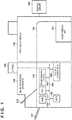
- Fig. 1 is a view showing the arrangement of a whole printing system that includes an image processing apparatus 100 serving as an image processing apparatus according to the first embodiment, and performs output and inspection of a printed product.
- the printing system according to the first embodiment includes the image processing apparatus 100 and a printing apparatus 190.
- the printing system according to the first embodiment may further include a printing server 180.
- the printing server 180 generates a print job including an original to be printed, and inputs the print job to the printing apparatus 190.
- the printing apparatus 190 forms an image on a print medium based on the print job input from the printing server 180.
- the printing apparatus 190 includes a sheet feeding unit 191, and the user can supply in advance print sheets to the sheet feeding unit 191.
- the printing apparatus 190 forms an image on one or two surfaces of a print medium supplied to the sheet feeding unit 191 while conveying the print medium along a conveyance path 192. Then, the printing apparatus 190 sends the print medium to the image processing apparatus 100.
- the image processing apparatus 100 inspects a defect on a print medium (inspection target medium) having undergone printing.
- the inspection target medium is obtained by forming an image on the print medium by the printing apparatus 190, and is conveyed through the conveyance path 192 inside the printing apparatus 190.
- the image processing apparatus 100 may incorporate a CPU 101, a RAM 102, and a ROM 103.
- the image processing apparatus 100 may include an image reading device 105, a printing apparatus interface (I/F) 106, a general-purpose interface (I/F), a user interface (UI) panel 108, and a main bus 109. Further, the image processing apparatus 100 may have a conveyance path 110 for a print medium that is connected to the conveyance path 192 of the printing apparatus 190.
- the image processing apparatus 100 may include an output tray 111 to which an inspection target medium determined to be accepted by inspection is output, and an output tray 112 to which an inspection target medium determined to be rejected by inspection is output.
- the output trays 111 and 112 are connected to the CPU 101 via the main bus 109.
- the output tray 111 or 112 is set as the conveyance destination of an inspection target medium in accordance with the result of inspection on the inspection target medium.
- the image processing apparatus can be implemented by a computer including a processor and a memory.
- the function of each unit shown in Figs. 2 , 6 , and the like to be described later can be implemented by executing a program stored in a memory such as the RAM 102 or the ROM 103 by a processor such as the CPU 101.
- the processor such as the CPU 101 can also control each module in the image processing apparatus 100, as needed.
- the image processing apparatus according to the embodiment of the present invention may be constituted by, for example, a plurality of processing apparatuses connected via a network.
- the CPU 101 is a processor that controls each unit in the image processing apparatus 100.
- the RAM 102 temporarily holds an application executed by the CPU 101, data used for image processing, or the like.
- the ROM 103 stores programs executed by the CPU 101.
- the image reading device 105 reads, on the conveyance path 110, one or two surfaces of a print medium sent from the printing apparatus 190, and obtains them as image data. Since the conveyance path 110 serves as a background when the image reading device 105 reads an image on a print medium, it can be constituted to have a color (for example, black) easily discriminable from a print medium on an image.
- the printing apparatus I/F 106 is connected to the printing apparatus 190, and the image processing apparatus 100 can communicate with the printing apparatus 190 via the printing apparatus I/F 106. For example, the printing apparatus 190 and the image processing apparatus 100 can be synchronized via the printing apparatus I/F 106 to notify each other of their operating situations.
- the UI panel 108 can output information to the user.
- the UI panel 108 may be a display device such as a liquid crystal display and can function as the user interface of the image processing apparatus 100.
- the UI panel 108 can notify the user of, for example, the current situation or settings of the image processing apparatus 100.
- the UI panel 108 may include an input device such as a touch panel or a button and can accept an instruction from the user.
- the main bus 109 is a transmission path that connects the modules of the image processing apparatus 100.
- the image processing apparatus 100 performs inspection processing to check the presence/absence of a defect on a print medium based on image data of the print medium obtained by the image reading device 105 while the print medium output from the printing apparatus 190 is conveyed along the conveyance path 110. If the print medium is determined to be accepted as a result of the inspection processing, it is conveyed to the output tray 111. If the print medium is determined to be rejected as a result of the inspection processing, it is conveyed to the output tray 112. By this operation, only print media determined to have no defect are output onto the output tray 111.
- Fig. 2 is a block diagram showing the functional arrangement of the image processing apparatus 100 according to the embodiment.
- Each rectangular frame represents a functional module that performs each processing according to the embodiment, and each arrow indicates a flow of data.
- the arrangement in Fig. 2 is merely an example, and the image processing apparatus 100 according to the embodiment is not limited to one shown in Fig. 2 .
- An image obtaining unit 201 obtains the first image serving as a read image of an inspection target medium having undergone printing, and the second image serving as a read image of a reference medium representing a target print result.
- the image obtaining unit 201 obtains image data obtained by reading a print medium on the conveyance path 110 by the image reading device 105.
- the image reading device 105 reads print media at least at two different times and generates respective image data of the print media.
- An image obtained by reading a reference medium at the first time by the image reading device 105 will be called a reference image 301, and an image obtained by reading an inspection target medium at the second or subsequent time will be called a target image 302.
- a region determination unit 202 determines a picture region 305 and a peripheral region 306 in each of the reference image 301 and the target image 302 obtained by the image obtaining unit 201.
- the region determination unit 202 can determine a region to which each pixel of image data belongs. In this embodiment, the region determination unit 202 divides the target image 302 into the picture region 305 and the peripheral region 306.
- the region determination unit 202 can also divide the reference image 301 into the picture region 305 and the peripheral region 306.
- a processing selection unit 203 sets an inspection to be performed by an inspection processing unit 205 in accordance with the type of a region determined by the region determination unit 202. In this embodiment, the processing selection unit 203 selects inspection processing used for each of the picture region 305 and the peripheral region 306.
- An alignment unit 204 aligns the reference image 301 and the target image 302.
- the alignment unit 204 can align images in accordance with the brightness of the images.
- the alignment unit 204 can align the reference image 301 and the target image 302 based on objects in the images. More specifically, the alignment unit 204 can calculate a geometric correction parameter so that when geometric correction is performed on one image, an object in one image comes close to an object in the other image.
- the alignment unit 204 performs alignment with the reference image 301 for the picture region 305 of the target image 302. For example, the alignment unit 204 can calculate a position displacement amount between images in the picture regions 305 of the target image 302 and reference image 301 based on the brightness of the picture region 305 observed from each of the target image 302 and the reference image 301.
- the position displacement amount calculated in this embodiment can include a translation amount, a rotation amount, and a scaling amount.
- the inspection processing unit 205 inspects a defect on an inspection target medium based on the reference image 301 and the target image 302. In this embodiment, the inspection processing unit 205 performs inspection at inspection settings different between the print region and peripheral region of an inspection target medium.
- the processing selection unit 203 makes inspection settings.
- the inspection processing unit 205 determines a defect based on a comparison between the target image 302 and the reference image 301. For example, the inspection processing unit 205 can calculate a difference between the reference image 301 and the target image 302 and perform inspection in a state in which the alignment unit 204 aligns them.
- the inspection processing unit 205 can determine that a portion having a large difference between the reference image 301 and the target image 302 is a defective portion.
- the inspection processing unit 205 determines a defect at an inspection setting different from that of the print region. A detailed method will be described later.
- FIG. 3 is a flowchart showing a sequence of processing performed by the image processing apparatus 100.
- step S1010 the image obtaining unit 201 obtains the reference image 301 obtained by reading a reference medium on the conveyance path 110 by the image reading device 105 in the above-described manner, and stores it in the RAM 102.
- the reference image 301 is used for subsequent processing to inspect each target image 302.
- step S1020 the image obtaining unit 201 obtains the target image 302 obtained by reading an inspection target medium on the conveyance path 110 by the image reading device 105 in the above-described manner, and stores it in the RAM 102.
- step S1030 to S1070 inspection of the target image 302 obtained in step S1020 is performed.
- the image reading device 105 can generate the reference image 301 by reading the reference medium.
- the image reading device 105 can generate the target image 302 by reading the inspection target medium.
- the embodiment is also applicable to a case in which the reference image 301 or the target image 302 obtained using another device is used.
- the reference image 301 or the target image 302 obtained by a device different from the image reading device 105 may be stored in an auxiliary storage device (not shown).
- the image obtaining unit 201 can obtain the reference image 301 or the target image 302 from the auxiliary storage device in step S1010 or S1020.
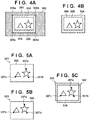
- Fig. 4A is a view showing an example of the target image 302.
- the target image 302 includes a print medium region 304 where a print medium is captured, and a background region 303 where no print medium is captured.
- the image reading device 105 reads the target image 302 so that the conveyance path 110 is captured as a background around the print medium region 304 in order to obtain the image of the entire print medium.
- the conveyance path 110 is black, so the background region 303 becomes black.
- the reference image 301 includes a print medium region where a print medium is captured, and a background region where no print medium is captured.
- the region determination unit 202 detects the picture region 305 and the peripheral region 306 in the target image 302 by performing region determination for the target image 302.
- the region determination unit 202 first extracts the print medium region 304 from the target image 302.
- the region determination unit 202 can extract the print medium region 304 in the following way.
- the region determination unit 202 binarizes the target image 302, traces pixels serving as the boundary between white pixels and black pixels, and linearly approximates four sides representing the outline of the print medium. As a result, four straight lines representing the outline of the print medium region 304 are estimated. Then, the region determination unit 202 calculates the intersection points of the four straight lines.
- intersection points correspond to vertices 308a to 308d of the print medium region 304 shown in Fig. 4A .
- the method of extracting the print medium region 304 is not limited to the above-described one, and another method is also available.
- the region determination unit 202 detects the picture region 305 and the peripheral region 306 from the print medium region 304 of the target image 302. In this embodiment, the region determination unit 202 determines to which of the picture region 305 and the peripheral region 306 each pixel constituting the print medium region 304 belongs.
- Fig. 4B shows the relationship between the target image 302, the print medium region 304, the picture region 305 (shown in Fig. 4B as a region where white and pictures exist), and the peripheral region 306 (hatched in Fig. 4B ).
- the inside of the print medium region 304 belongs to either the picture region 305 or the peripheral region 306.
- the region determination unit 202 can determine, as the peripheral region 306, a region within a predetermined distance from the outline of the medium on the reference image 301 or the target image 302. For example, the region determination unit 202 can extract, as the peripheral region 306, a region within a predetermined distance from the outline of the print medium region 304, and extract the remaining region as the picture region 305.
- the predetermined distance that defines the peripheral region 306 can be called a peripheral margin and set in advance by the user prior to processing.
- the method of detecting the peripheral region 306 is not limited to the above-described one.
- the region determination unit 202 can detect a marker applied to a medium on the reference image 301 or the target image 302, and determine the peripheral region 306 based on the coordinates of the marker. More specifically, when an alignment marker such as a register mark is printed on a print medium, the region determination unit 202 may set a peripheral margin based on the coordinates of the alignment marker. The peripheral margin may be set based on a margin amount or a print position error amount when the printing apparatus 190 prints on a medium on the reference image 301 or the target image 302.
- the region determination unit 202 may obtain information representing the average values of a margin size and print error amount at the time of printing from the printing apparatus 190, and set the sum of the average values of the margin size and print error amount as the peripheral margin. Further, the region determination unit 202 may determine the plain region of the print medium region 304 as the peripheral region 306 and the remaining region as the picture region 305.
- the region determination unit 202 calculates feature information (in this example, average brightness) about the peripheral region 306 detected from the reference image 301.
- the feature information is used in step S1060, details of which will be described later.
- the region determination unit 202 can extract the print medium region 304 of the reference image 301. Also, the region determination unit 202 can extract the picture region 305 and peripheral region 306 of the reference image 301. Note that the image obtaining unit 201 may extract the print medium region 304, picture region 305, and peripheral region 306 of the reference image 301 in step S1010.
- step S1040 the processing selection unit 203 selects the details of detection processing to be performed for the picture region 305 in step S1060, and those of inspection processing to be performed for the peripheral region 306 in step S1070.
- step S1060 defect determination is performed for the picture region 305 at the settings selected by the processing selection unit 203.
- step S1070 defect determination is performed for the peripheral region 306 at the settings selected by the processing selection unit 203.
- the details of inspection processing selected by the processing selection unit 203 can be set in advance by the user prior to processing.
- the processing selection unit 203 selects defect determination processing based on a comparison between the reference image 301 and the target image 302 for the picture region 305, and defect determination processing based on a comparison between the target image 302 and feature information for the peripheral region 306.
- step S1050 the alignment unit 204 aligns the reference image 301 and the target image 302.
- defect determination processing based on a comparison between the reference image 301 and the target image 302 is performed only for the picture region 305.
- the alignment unit 204 aligns the reference image 301 and the target image 302 based on the picture region 305.
- Fig. 5A shows the picture region 305 and reference points 307a to 307c in the reference image 301.
- Fig. 5B shows the picture region 305 and the reference points 307a to 307c in the target image 302.
- the reference point 307 is a point indicating the same portion of the same object in the picture regions 305 of the reference image 301 and the target image 302, and is also called a feature point.
- the three reference points 307a to 307c are set and used for alignment.
- the same reference numerals denote corresponding reference points.
- the reference point 307a of the reference image 301 and the reference point 307a of the target image 302 indicate the same portions of a picture though the coordinates in the respective images are different. This also applies to the reference points 307b and 307c.
- the positions of the reference points 307a to 307c with respect to a picture to be printed by the printing apparatus 190 are set in advance.
- the user may manually set the reference points 307a to 307c while checking the picture.
- the reference points 307a to 307c may be automatically set using an image feature amount such as SIFT or SURF
- the alignment unit 204 can detect the set reference points 307a to 307c by image analysis on the picture regions 305 of the reference image 301 and the target image 302. In this embodiment, printing is performed on an inspection target medium in accordance with preset print data, so rough appearance positions of the reference points can be predicted.
- the alignment unit 204 can detect the reference points 307a to 307c by setting windows of a predetermined size (for example, 32 ⁇ 32 pixels) near the predicted positions of the reference points 307a to 307c, and performing template matching. As another method, the alignment unit 204 may detect the reference points 307a to 307c using processing of detecting an image feature amount such as SIFT or SURF mentioned above.
- a predetermined size for example, 32 ⁇ 32 pixels
- the alignment unit 204 detects the reference points 307a to 307c, obtaining the coordinates of the respective reference points 307a to 307c in each of the reference image 301 and the target image 302.
- the coordinates of the reference points 307a, 307b, and 307c in the reference image 301 are defined as (x1a, y1a), (x1b, y1b), and (x1c, y1c), respectively.
- the coordinates of the reference points 307a, 307b, and 307c in the target image 302 are defined as (x2a, y2a), (x2b, y2b), and (x2c, y2c).
- the alignment unit 204 aligns the reference image 301 and the target image 302 based on the positions of the corresponding reference points 307a to 307c detected from the reference image 301 and the target image 302. For example, when geometric transformation is applied to the reference image 301, the alignment unit 204 can calculate a geometric transformation for alignment so that the positions of the reference points 307a to 307c in the reference image 301 and the target image 302 match with each other.
- the alignment unit 204 calculates a transformation X of the picture region 305 from the reference image 301 to the target image 302 according to equation (1):
- AX B
- A x 1 a y 1 a 1 x 1 b y 1 b 1 x 1 c y 1 c 1
- B x 2 a y 2 a 1 x 2 b y 2 b 1 x 2 c y 2 c 1
- X x 11 x 12 x 13 x 21 x 22 x 23 0 0 1
- X is an affine transformation and represents a displacement amount obtained by combining translation, rotation, scaling, and shearing from the reference image 301 to the target image 302.
- the transformation X can be calculated by multiplying the inverse matrix of A from the right side of B in equation (1).
- the alignment unit 204 After that, the alignment unit 204 generates a transformed image 309 by applying the calculated transformation X to each pixel constituting the print medium region 304 in the reference image 301. As shown in Fig. 5C , the picture in the picture region 305 of the generated transformed image 309 is aligned with the target image 302. That is, the positions of the reference points 307a to 307c in the transformed image 309 and the target image 302 match with each other. In this manner, the alignment unit 204 can align the reference image 301 and the target image 302.
- step S1060 the inspection processing unit 205 performs for the peripheral region 306 inspection processing selected by the processing selection unit 203 in step S1040.
- the inspection processing unit 205 performs defect determination processing based on a comparison between the target image 302 and feature information for the peripheral region 306. More specifically, the inspection processing unit 205 can detect a defect in the peripheral region 306 of the inspection target medium by comparing image information at each position of the peripheral region 306 of the target image 302 with feature information having a predetermined value.
- the image information at each position of the peripheral region 306 of the target image 302 may be the brightness of each pixel.
- the feature information (to be referred to as a feature value hereinafter) having a predetermined value may be feature information about the peripheral region 306.
- the feature information may be, for example, the representative brightness of pixels belonging to the peripheral region 306.
- the representative brightness is a brightness representing the peripheral region 306. For example, when a print medium is white paper, the representative brightness may be the typical brightness of white paper read by the image obtaining unit 201.
- the inspection processing unit 205 uses, as the feature value, feature information about the peripheral region 306 of the reference image 301 obtained by the image obtaining unit 201. In this embodiment, the inspection processing unit 205 uses, as the feature value, the average brightness of the peripheral region 306 detected from the reference image 301 in step S1030. Then, the inspection processing unit 205 calculates a difference between the pixel value and the feature value for each pixel of the peripheral region 306 of the target image 302. The inspection processing unit 205 can determine that a pixel having a calculated difference larger than a threshold is a defective pixel.
- the inspection processing unit 205 may use a preset value as the feature value instead of the representative brightness of the peripheral region 306 detected from the reference image 301.
- the feature value can be set in advance in accordance with the type of print medium. This setting can omit the processing of detecting the peripheral region 306 of the reference image 301 by the region determination unit 202. Even when a print position error occurs, a printed product can be inspected properly.
- step S1070 the inspection processing unit 205 performs for the picture region 305 inspection processing selected by the processing selection unit 203 in step S1040.
- the inspection processing unit 205 performs defect determination processing based on a comparison between the reference image 301 and the target image 302 for the picture region 305. More specifically, the inspection processing unit 205 detects a defect in the picture region 305 of the inspection target medium by comparing the target image 302 and reference image 301 aligned based on objects in the images.
- the alignment unit 204 generates the transformed image 309 by alignment processing of the reference image 301 to the target image 302 in step S1050.
- the inspection processing unit 205 calculates a difference between the target image 302 and the transformed image 309 for each pixel of the picture region 305 in the target image 302.
- the inspection processing unit 205 can determine that a pixel having a calculated difference larger than a threshold is a defective pixel.
- the inspection processing unit 205 When the inspection processing unit 205 detects a defective pixel in step S1060 or S1070, the inspection target medium is determined to be rejected. At this time, the CPU 101 of the image processing apparatus 100 controls to convey the inspection target medium to the output tray 112. When the inspection processing unit 205 detects no defective pixel, the inspection target medium is determined to be accepted. At this time, the CPU 101 of the image processing apparatus 100 controls to convey the inspection target medium to the output tray 111.
- step S1080 the inspection processing unit 205 determines whether to convey the next inspection target medium to the image processing apparatus 100. If the printing apparatus 190 further prints on a print medium and the inspection target medium is conveyed to the image processing apparatus 100, the process returns to step S1020 to continue the processing in Fig. 3 . If printing and inspection end, the processing in Fig. 3 ends.
- the alignment unit 204 aligns the reference image 301 and the target image 302 by transforming the reference image 301 using the transformation X in step S1050.
- the alignment unit 204 may align the target image 302 with respect to the reference image 301 by transforming the target image 302.
- a transformed image can be generated by transforming the target image 302 using a different transformation Y.
- the matrices A and B are the same as those in equation (1).
- the inspection processing unit 205 can calculate a difference between the reference image 301 and the transformed image in step S1070.
- inspection processing corresponding to a region is performed for each of the picture region and the peripheral region on an inspection target medium.
- defect determination processing based on a comparison between the reference image 301 and the target image 302 is used for the picture region 305, and defect determination processing based on a comparison between the target image 302 and feature information is used for the peripheral region 306.
- a combination of the inspection setting used for defect determination of the picture region 305 and the inspection setting used for defect determination of the peripheral region 306 is not limited to this.
- the processing selection unit 203 may select defect determination processing based on a comparison between the reference image 301 and the target image 302 even for the peripheral region 306. In this case, the processing selection unit 203 can set, as the threshold used for defect determination by the inspection processing unit 205, values different between inspection of the picture region 305 and that of the peripheral region 306.
- the inspection processing unit 205 can detect a defect in the picture region 305 of an inspection target medium by comparing with the first threshold a difference between the transformed image 309 and the target image 302 in the picture region 305.
- the inspection processing unit 205 can detect a defect in the peripheral region 306 of the inspection target medium by comparing, with the second threshold different from the first threshold, a difference between the transformed image 309 and the target image 302 in the peripheral region 306. Even with this arrangement, an inspection can be performed at inspection settings different between the picture region 305 and the peripheral region 306.
- the processing selection unit 203 detects a defect in the picture region 305 of an inspection target medium, whereas it can omit detection of a defect in the peripheral region 306 of the inspection target medium.
- the inspection method may be set not to perform defect determination for the peripheral region 306 based on an input from the user or a setting. Even with this arrangement, an inspection can be performed at inspection settings different between the picture region 305 and the peripheral region 306. Further, the processing selection unit 203 may set the inspection method so as to perform defect determination using the same method between the picture region 305 and the peripheral region 306 based on an input from the user or a setting.
- the presence/absence of a defect on an inspection target medium is inspected using inspection processing corresponding to each of the picture region and the peripheral region.
- a defect is determined based on a comparison between a reference image and a target image also for the peripheral region of an inspection target medium.
- alignment processing corresponding to each of the picture region and the peripheral region is performed to determine a defect at inspection settings different between the picture region and the peripheral region.
- the functional arrangement of an image processing apparatus 100 according to the second embodiment is similar to that of the image processing apparatus 100 according to the first embodiment shown in Fig. 2 , and a difference from the first embodiment will be described below.
- a processing selection unit 203 selects inspection settings for a picture region 305 and a peripheral region 306. In the second embodiment, the processing selection unit 203 selects the details of alignment processing for inspection of the picture region 305, and those of alignment processing for inspection of the peripheral region 306.
- An alignment unit 204 aligns a reference image 301 and a target image 302 by the first method for inspection of the picture region 305.
- the alignment unit 204 aligns the reference image 301 and the target image 302 based on the picture region 305 for inspection of the picture region 305.
- An inspection processing unit 205 compares the aligned reference image 301 and the target image 302, detecting a defect in the picture region 305 of the inspection target medium.
- the alignment unit 204 aligns the reference image 301 and the target image 302 by the second method for inspection of the peripheral region 306.
- the alignment unit 204 aligns the reference image 301 and the target image 302 based on the periphery positions of the inspection target medium and reference medium for inspection of the peripheral region 306.
- the inspection processing unit 205 compares the aligned reference image 301 and the target image 302, detecting a defect in the peripheral region 306 of the inspection target medium. Details of this processing will be described below.
- steps S1010 to S1030 are similar to those in the first embodiment.
- the processing selection unit 203 selects the details of alignment processing for the picture region 305 and those of alignment processing for the peripheral region 306 that are performed in step S1050, as described above.
- alignment processing using affine transformation based on reference points 307a to 307c is selected for the picture region 305.
- alignment processing using affine transformation based on the positions of four vertices of a print medium is selected.
- the reference image 301 and the target image 302 are aligned based on the picture region 305 in step S1050 similarly to the first embodiment. That is, the alignment unit 204 can calculate the transformation X based on the reference points 307a to 307c for the reference image 301, and generate a transformed image 309 by applying the transformation X to the reference image 301. In step S1050, the alignment unit 204 aligns the reference image 301 and the target image 302 based on the peripheral region 306.
- Figs. 8A to 8C are views for explaining an outline of alignment processing based on the peripheral region 306.
- Figs. 8A and 8B show the relationship between the reference image 301, the target image 302, the picture region 305, the peripheral region 306, and vertices 308a to 308d of a print medium region 304.
- the alignment unit 204 aligns the reference image 301 and the target image 302 based on the coordinates of the vertices 308a to 308d of the respective print medium regions 304 in the reference image 301 and the target image 302 that have been detected in step S1030.
- the alignment unit 204 can calculate a geometric transformation for alignment so that the positions of the vertices 308a to 308d in the reference image 301 and the target image 302 match with each other.
- the alignment unit 204 can calculate a transformation X' of the peripheral region 306 from the reference image 301 to the target image 302 according to equation (3):
- a ⁇ X ⁇ B ⁇
- A x 1 a y 1 a 1 x 1 b y 1 b 1 x 1 c y 1 c 1 x 1 d y 1 d
- B x 2 a y 2 a 1 x 2 b y 2 b 1 x 2 c y 2 c 1 x 2 d y 2 d
- X x 11 x 12 x 13 x 21 x 22 x 23 0 0 1 Since A' and B' in equation (3) are not square matrices, the alignment unit 204 calculates a Moore
- the alignment unit 204 generates a periphery transformed image 310 by applying the calculated transformation X' to each pixel in the print medium region 304 of the reference image 301.
- Fig. 8C shows a state in which the target image 302 is aligned by alignment processing with the periphery transformed image 310 obtained by transforming the reference image 301 using the transformation X'.
- the positions of the vertices 308a to 308d of the print medium regions 304 and the positions of the peripheral regions 306 in the periphery transformed image 310 and the target image 302 match with each other.
- the positions of the picture regions 305 in the periphery transformed image 310 and the target image 302 may not match with each other.
- the alignment unit 204 generates an overall transformed image 311 by compositing the periphery transformed image 310 and the transformed image 309.
- Figs. 9A to 9C are views for explaining the overall transformed image 311.
- the alignment unit 204 generates the overall transformed image 311 by combining an image corresponding to the picture region 305 of the target image 302 out of the transformed image 309 and an image corresponding to the position of the peripheral region 306 of the target image 302 out of the periphery transformed image 310. Since the picture region 305 and peripheral region 306 of the target image 302 do not overlap each other, the alignment unit 204 can generate the unique overall transformed image 311.
- the generated overall transformed image 311 corresponds to the result of aligning the overall reference image 301 with the target image 302.
- steps S1060 and S1070 can be performed simultaneously. That is, the inspection processing unit 205 can calculate a difference between the target image 302 and the overall transformed image 311 for each pixel of the target image 302. The inspection processing unit 205 can determine that a pixel having a calculated difference larger than a threshold is a defective pixel. Processing in step S1080 is similar to that in the first embodiment. In this fashion, the processing according to the second embodiment can be performed.
- step S1050 it is not essential to generate the overall transformed image 311 in step S1050.
- a defect may be detected using different transformed images for the picture region 305 and the peripheral region 306.
- the inspection processing unit 205 can calculate a difference between the periphery transformed image 310 and the target image 302 for each pixel in the peripheral region 306, and compare the difference with a threshold.
- step S1070 the inspection processing unit 205 can calculate a difference between the transformed image 309 and the target image 302 for each pixel in the picture region 305, and compare the difference with a threshold.
- inspection processing using different alignment processing corresponding to a region is performed for each of the picture region and the peripheral region on an inspection target medium.
- image comparison is performed even in the peripheral region, and a defect near the periphery of a medium can be detected more accurately.
- a defect in a target image is detected by comparing the target image with a reference image in at least the picture region. Even in a conventional technique, a defect in a target image is detected by comparing the target image with a reference image.
- a reference image is obtained by reading a reference medium.
- a reference image is generated based on the reading results of reference media. For example, in the third embodiment, a reference image can be generated based on read images obtained by reading respective reference media. This arrangement increases the S/N ratio of the reference image, and high accuracy of defect inspection is expected.
- a print position error occurs on each of reference media, read images need to be aligned before compositing them. If alignment is performed to make pictures match with each other even in this case, similar to the first and second embodiments, a mismatch at the peripheries of the media increases, and an improper reference image may be generated. Therefore, in the third embodiment, a picture region and a peripheral region on a reference medium are determined, and a plurality of read images are composited into a reference image by compositing processing corresponding to each region. The thus-generated reference image can be used to increase the accuracy of inspection according to the first and second embodiments. The reference image generated according to the third embodiment can also be used in inspection according to the conventional technique.
- Fig. 6 is a block diagram showing the functional arrangement of an image processing apparatus 100 according to the third embodiment.
- the functional arrangement of the image processing apparatus 100 according to the third embodiment is similar to that of the image processing apparatus 100 according to the first embodiment shown in Fig. 2 , and a difference from the first embodiment will be explained.
- An image obtaining unit 201 obtains the first image serving a read image of a reference medium representing a target print result, and the second image different from the first image.
- an image obtained by reading a reference medium at the first time by an image reading device 105 will be called the first read image
- an image obtained by reading another reference medium at the second or subsequent time will be called the second read image.
- the image obtaining unit 201 is similar to that in the first embodiment except that it obtains the first and second read images instead of a reference image 301 and a target image 302.
- the image obtaining unit 201 can obtain a plurality of second read images by reading respective reference images.
- the second read images can be sequentially composited to the first read image.
- the first read image or the first read image to which one or more second read images are composited will sometimes be called a processed image.
- a region determination unit 202, a processing selection unit 203, and an alignment unit 204 are similar to those in the first embodiment except that they process the processed image and the second read image instead of the reference image 301 and the target image 302.
- a compositing processing unit 206 composites the first and second read images.
- the compositing processing unit 206 can generate a reference image that is compared with a read image of an inspection target medium in order to detect a defect on the inspection target medium having undergone printing.
- the compositing processing unit 206 performs compositing processing at compositing settings different between a picture region 305 and peripheral region 306 of the medium.
- the compositing processing unit 206 can generate a reference image by repeating compositing processing of the second read image to a processed image. An image obtained by compositing one second read image to a processed image will be called a composite image.
- the compositing processing unit 206 generates an image in the picture region 305 of a composite image by compositing a processed image and the second read image.
- the compositing processing unit 206 generates an image in the picture region 305 of the composite image by compositing the processed image and the second read image in accordance with alignment by the alignment unit 204.
- the compositing processing unit 206 generates an image in the picture region 305 of the composite image by compositing the processed image and second read image aligned based on an object in the image.
- the compositing processing unit 206 generates information used to inspect the peripheral region 306 on an inspection target medium at a compositing setting different from that of the picture region 305.
- the compositing processing unit 206 composites pieces of feature information of images in the peripheral regions 306 of media out of the processed image and the second read image. Such feature information can be used to inspect a peripheral region on an inspection target medium (target image 302) in the first embodiment.
- the compositing processing unit 206 sets a pixel value in the peripheral region 306 of a composite image at a feature value obtained by compositing the feature value of the peripheral region 306 of the processed image and that of the peripheral region 306 of the second read image.
- the obtained composite image including the picture region 305 in which the aligned processed image and the second read image are composited, and the peripheral region 306 having a predetermined pixel value can be used as a reference image in the first and second embodiments.
- Fig. 7 is a flowchart showing a sequence of processing performed by the image processing apparatus 100.
- a plurality of second read images are sequentially composited to the first read image.
- step S1010 the image obtaining unit 201 obtains the first read image similarly to the first embodiment except that the first read image is obtained instead of the reference image 301.
- the obtained first read image is used as a processed image.
- step S1020 the image obtaining unit obtains the second read image similarly to the first embodiment except that one of the second read images is obtained instead of the target image 302.
- step S1040 the processing selection unit 203 selects the details of compositing processing to be performed for the picture region 305 in step S1100, and those of compositing processing to be performed for the peripheral region 306 in step S1110.
- compositing processing based on averaging of the processed image and the second read image is selected for the picture region 305, and compositing processing based on the feature value is selected for the peripheral region 306.
- a detailed processing selection method is similar to that in the first embodiment.
- step S1050 the alignment unit 204 aligns the processed image and the second read image.
- the processed image and the second read image are aligned based on the picture region 305.
- the alignment unit 204 can calculate the transformation X of the picture region 305 from the processed image to the second read image based on reference points.
- the alignment unit 204 generates a transformed image by applying the calculated transformation X to each pixel constituting a print medium region 304 in the processed image. As a result, the alignment unit 204 can align the processed image and the second read image.
- step S1100 the inspection processing unit 205 performs for the peripheral region 306 compositing processing selected by the processing selection unit 203 in step S1040.
- the compositing processing unit 206 performs compositing processing based on the feature value for the peripheral region 306.
- the feature value in this embodiment is the representative brightness of pixels belonging to the peripheral region 306.
- the significance of the feature value may be similar to that in the first embodiment.
- the average brightness of pixels belonging to the peripheral region 306 is used as the feature value.
- the compositing processing unit 206 performs compositing processing using the feature value for each pixel of the peripheral region 306 in the second read image. More specifically, the compositing processing unit 206 calculates the average of a feature value (in this example, the average brightness of the peripheral region 306) in the second read image and a feature value in the processed image for each pixel of the peripheral region 306.
- a feature value in this example, the average brightness of the peripheral region 306
- the compositing processing unit 206 can replace, with the feature value of the peripheral region 306, the pixel values of all pixels belonging to the peripheral region 306 of the second read image.
- the feature value is the average brightness of all pixels belonging to the peripheral region 306 of the second read image.
- the pixel value of the peripheral region 306 in the first read image is replaced with the average brightness of the peripheral region 306 of the first read image in step S1030.
- the thus-obtained composite image is used as a processed image in the next processing loop, so all the pixels of the peripheral region 306 of the composite image have the same value even in subsequent processing loops.
- the I 3 (x, y) value obtained from equation (4) is the average value (I 1 (x, y)) of the processed image and the average value (I 2 (x, y)) of the second read image, which are weighted by the number of composited read images.
- the I 3 (x, y) value is the average brightness of the peripheral regions 306 of the first and second read images processed so far.
- step S1110 the compositing processing unit 206 performs for the picture region 305 compositing processing selected by the processing selection unit 203 in step S1040.
- the compositing processing unit 206 performs compositing processing based on averaging of the processed image and the second read image for the picture region 305.
- the compositing processing unit 206 can composite the second read image and a transformed image obtained from the processed image by alignment processing in step S1050 for each pixel of the picture region 305 in the second read image.
- the compositing processing unit 206 can calculate the pixel value of each pixel (x, y) of the picture region 305 of the composite image using equation (4) described above (in this case, I 1 (x, y) is the pixel value of the transformed image).
- steps S1100 and S1110 the composite image including the picture region 305 and the peripheral region 306 is generated.
- step S1120 the compositing processing unit 206 determines whether there is a read image of a reference medium which has not been composited yet.
- the image obtaining unit 201 replaces the processed image with the composite image.
- the process returns to step S1020 to composite the processed image with the second read image of a new reference medium.
- steps S1100 and S1110 in the next processing loop the N value used in equation (4) is incremented by one.
- the compositing processing unit 206 determines in step S1120 that read images of all reference media have been composited, the generated composite image is output to an auxiliary storage device (not shown), and the processing in Fig. 7 ends.
- the output composite image can be used as the reference image 301 in the first and second embodiments. By using the composite image generated in this way as the reference image 301, high accuracy of inspection processing in the first and second embodiments is expected.
- the compositing processing unit 206 generates a composite image by sequentially calculating an average according to equation (4) while repeating steps S1020 to S1120.
- the composite image generation method is not limited to this.
- the image obtaining unit 201 can obtain a plurality of second read images as the reading results of a plurality of reference media.
- the compositing processing unit 206 may composite all the first and second read images.
- the pixel value of the peripheral region 306 in a read image is replaced with the average brightness of the peripheral region 306. Then, read images are composited according to equation (4) or the like, generating a composite image in which the peripheral region 306 has a predetermined pixel value.
- the compositing processing unit 206 may generate feature information about the peripheral region 306 of a reference image by another method. For example, the compositing processing unit 206 may calculate the average brightness of the peripheral regions 306 of the first and second read images and output it as feature information about the peripheral region 306 of the reference image.
- This feature information can be used as feature information about the peripheral region 306 having a predetermined value that is compared with image information at each position of the peripheral region 306 of the target image 302 in the first embodiment.
- the compositing processing unit 206 can output a reference image generated by compositing a processed image and second read image aligned based on an object in the picture region 305, and feature information about the peripheral region 306 of this reference image.
- the compositing processing unit 206 may generate a reference image by compositing a processed image and second read image aligned based on an object in the picture region 305, and replacing the pixel value of the peripheral region 306 of the obtained image with the feature information.
- a reference image is obtained by determining the picture region and peripheral region of a reference medium, and compositing read images of a plurality of reference media using compositing processing corresponding to each region.
- the picture region and peripheral region of a reference medium are determined, and a plurality of read images are composited into a reference image by compositing processing corresponding to each region.
- the compositing processing of a reference image is performed at compositing settings different between the picture region and the peripheral region by performing alignment processing corresponding to each of the picture region and the peripheral region.
- the functional arrangement of an image processing apparatus 100 according to the fourth embodiment is similar to that of the image processing apparatus 100 according to the third embodiment shown in Fig. 6 , and a difference from the third embodiment will be described below.
- a processing selection unit 203 selects the details of compositing processing for a picture region 305 and a peripheral region 306.
- the processing selection unit 203 selects alignment processing based on reference points in the picture region 305.
- the processing selection unit 203 selects alignment processing based on the positions of four vertices of a print medium in the peripheral region 306.
- the details of alignment processing performed by an alignment unit 204 are similar to those in the second embodiment.
- a compositing processing unit 206 generates a composite image. Similar to the third embodiment, the picture region 305 of the composite image is a composite image of a processed image and second read image aligned based on an object in the image. The peripheral region 306 of the composite image is a composite image of a processed image and second read image aligned based on the periphery position of the medium. The thus-obtained composite image can also be used as a reference image in the first and second embodiments.
- steps S1010 to S1030 are similar to those in the third embodiment.
- Processing in step S1040 is also similar to that in the third embodiment except that the processing selection unit 203 selects the details of compositing processing in the above-described manner.
- step S1050 the alignment unit 204 performs processing as in the second embodiment except that a processed image and the second read image are aligned.
- the transformation X' of the peripheral region 306 from the processed image to the second read image, and the transformation X of the picture region 305 from the processed image to the second read image are obtained.
- An overall transformed image obtained by the processing in step S1050 has, in a region corresponding to the position of the peripheral region 306 of the second read image, a peripheral transformed image obtained by transforming the processed image using the transformation X'. Further, the overall transformed image has, in a region corresponding to the position of the picture region 305 of the second read image, a transformed image obtained by transforming the processed image using the transformation X.
- step S1100 the compositing processing unit 206 generates a composite image by compositing the overall transformed image obtained in step S1050 and the second read image.
- the compositing processing unit 206 can perform calculation according to equation (4) for each pixel of the print medium region 304 (that is, both the picture region 305 and the peripheral region 306) of the second read image.
- I1(x, y) represents the pixel value of the overall transformed image.
- a composite image having the pixel value I 3 (x, y) calculated according to equation (4) can be generated.
- Processing in step S1120 is similar to that in the third embodiment.
- the fourth embodiment even when a print position error occurs, a more proper inspection reference image can be generated. Particularly in the fourth embodiment, image compositing processing is performed even in the peripheral region, and a defect near the periphery of a medium can be detected more accurately.
- alignment processing based on the positions of four vertices of a print medium in the peripheral region 306 is performed as an alignment method when performing inspection of the peripheral region 306.
- pixels in a predetermined search range are compared as shown in Fig. 10B , details of which will be described later.
- the inspection of a peripheral region 306 can therefore be performed using images in inspection ranges cut out from the reference image and the target image to have a region of a predetermined number of pixels around a print medium region 304.
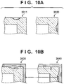
- a reference image 2011 obtained by compositing read images of a plurality of reference media may have a dark portion generated by compositing paper white and a black background at the periphery of the image.
- the black background portion may be captured at a periphery corresponding to the paper white portion of the print medium region 304 in a target image 2020.
- a reference image can be generated to include a background region at the periphery.
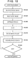
- Processing in the fifth embodiment is different from that in the fourth embodiment in processing of compositing the peripheral regions of a plurality of reference images. This processing in the fifth embodiment will be described below with reference to the flowchart of Fig. 11 .
- the following processing can be used in combination with processes such as alignment and compositing processing of a picture region in the fourth embodiment. That is, a composite image can be generated by performing compositing processing of a picture region 305 according to steps S1030 to S1110 in Fig. 7 while compositing the peripheral region 306 and a margin region according to steps S1180 to S1210 in Fig. 11 .
- an image obtaining unit 201 obtains the second read image as in step S1020 of the fourth embodiment.
- a region determination unit 202 extracts a margin region in addition to the peripheral region 306.
- the margin region is a region of a predetermined pixel width provided on upper, lower, right, and left sides around the peripheral region 306 (or print medium region 304).
- the pixel width is not particularly limited, the predetermined pixel width is set to 20 pixels in the following description. Similar to the above-described peripheral margin, a predetermined pixel width may be set based on a margin amount or print position error amount generated when a printing apparatus 190 prints.
- the margin region can be extracted to include the black region of the background. If an error of the print position of the printing apparatus with respect to the print medium is about 10 pixels, the width of the margin region can be set to about 10 pixels.
- a mechanism for setting a predetermined pixel width by the user may be provided separately.
- an alignment unit 204 aligns a processed image and the second read image based on the peripheral region 306 as in step S1050 of the fourth embodiment. That is, the alignment unit 204 can perform alignment processing based on the positions of four vertices of a print medium in the peripheral region 306. Similar to the fourth embodiment, the alignment unit 204 can transform the processed image so as to align the processed image with the second read image.
- step S1200 the alignment unit 204 obtains regions corresponding to the peripheral region 306 and the margin region from the transformed processed image obtained in step S 1190.
- the obtained image includes black pixels corresponding to the background region around the print medium region 304, like a reference image 2030 in Fig. 10B .
- step S1210 the compositing processing unit 206 composites the second read image and the transformed processed image obtained in step S 1190 in the peripheral region 306 and the margin region.
- the compositing processing unit 206 can generate the peripheral region 306 and margin region of the composite image serving as a composite image of the processed image and second read image aligned based on the periphery position of the medium.
- the compositing processing unit 206 can generate a composite image by sequentially calculating an average according to equation (4) as in the fourth embodiment for both the peripheral region 306 and the margin region.
- the compositing processing unit 206 may calculate a difference in pixel value between images and if the difference exceeds a predetermined threshold, employ the pixel value of an image having a smaller pixel value without averaging, in order to hold the contrast between the margin region and paper white at the periphery of the image.
- the compositing processing unit 206 may adopt another method of, for example, when the pixel value of the second read image is smaller than a predetermined threshold, replacing it with a predetermined pixel value representing a black region.
- the compositing processing unit 206 can generate the picture region 305 and margin region of the composite image serving as a composite image of the processed image and second read image aligned based on the picture region 305. Accordingly, the composite image including the picture region 305, the peripheral region 306, and the margin region can be generated.
- step S1220 Processing in step S1220 is similar to that in the fourth embodiment. After the end of compositing read images of all reference media, the generated composite image is output to an auxiliary storage device (not shown), and the processing ends. By this processing, a reference image in which read images of reference media including the background region at the periphery is obtained.
- step S1230 the image obtaining unit 201 obtains a reference image including the background region at the periphery.
- the reference image may be a composite image generated according to the above-described method by compositing read images of a plurality of reference media.
- step S1240 the image obtaining unit 201 obtains a target image as in step S1020 of the second embodiment.
- an inspection processing unit 205 extracts the picture region 305, the peripheral region 306, and the margin region from the target image.
- the method of extracting the picture region 305 and the peripheral region 306 is similar to that in the second embodiment.
- the method of extracting the margin region has been described above.
- the inspection processing unit 205 can generate an image in which the margin region is provided around the periphery of the print medium region 304.
- step S1260 similar to the second embodiment, the inspection processing unit 205 aligns the reference image obtained in step S1230 and the processed image obtained in step S1250.
- the inspection processing unit 205 can transform the reference image into an overall transformed image by performing alignment for the picture region 305 and alignment for the peripheral region 306.
- the inspection processing unit 205 can perform alignment based on the positions of four vertices of the print medium.
- the inspection processing unit 205 decides a search range used to compare the pixel values of the reference image and the target image.
- the margin region around the print medium region 304 is also extracted, and a detection error in the peripheral region can be suppressed by comparing pixel values in a predetermined range.
- the size of the search range is not particularly limited and can be 20 pixels, which is equal to the width of the margin region in the following description. Alternatively, similar to the width of the margin region, the size of the search range may be determined based on a margin amount or a print position error amount when the printing apparatus 190 prints.
- the inspection processing unit 205 calculates the difference value of each value between the target image and the reference image in the peripheral region 306. As shown in Fig. 10B , the inspection processing unit 205 can calculate a difference value between the pixel value of a pixel of interest of a reference image 2040 and the pixel value of each pixel of the reference image 2030 in the search range that corresponds to the pixel of interest.
- the search range may be a region whose vertical and horizontal distances from a pixel corresponding to the pixel of interest in the reference image are equal to or shorter than the number of pixels decided in step S1270.
- the inspection processing unit 205 can calculate a difference value for each pixel by scanning the reference image in the vertical and horizontal directions by the number of pixels corresponding to the search range, and employ a minimum difference value as a difference used for defect determination.
- step S1290 the inspection processing unit 205 determines whether the calculation of a difference value has ended for all the pixels of the target image. If the calculation has not ended, the process returns to step S1280 to calculate a difference value for another pixel. If the calculation has ended, the inspection processing unit 205 determines based on the difference value whether the pixel of the peripheral region 306 of the target image is a defective pixel, similarly to the second embodiment. Then, the inspection processing ends.
- an inspection image having a margin region around a print medium region is used.
- a minimum value among the difference values of pixels in a predetermined range is adopted as a difference value used for defect determination. For example, even when the pixel of interest of a target image represents paper white and a corresponding pixel of a reference image represents the background, if a pixel of the same color (pixel representing paper white) as that of the pixel of interest exists near the corresponding pixel of the reference image, the pixel is not determined as a defect.
- inspection and alignment are performed for each of the picture region and the peripheral region.
- inspection or alignment may be performed at an inspection setting or alignment setting for three or more regions.
- a method will be described in which a preprint region is newly added to inspection target regions and an image on a print medium is divided into three regions and processed.
- the preprint region is the region of an image printed in advance on a print medium before actual printing by a printing apparatus. Note that the preprint region may exist at the center of the print medium.
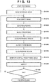
- Alignment processing and inspection processing for the preprint region in the sixth embodiment which is a difference from the second embodiment, will be explained below with reference to the flowchart of Fig. 13 .
- Alignment processing and inspection processing for the picture region and the peripheral region in the sixth embodiment are similar to those in the second embodiment, and a description thereof will not be repeated.
- an image obtaining unit 201 obtains a reference image serving as a read image of a reference medium representing a target print result.
- the image obtaining unit 201 obtains a target image serving as a read image of an inspection target medium having undergone printing.
- a region determination unit 202 performs region determination on the target image.
- the region determination unit 202 extracts a picture region, a peripheral region, and a preprint region from the target image.
- the region determination unit 202 can extract the picture region, the peripheral region, and the preprint region by referring to a region map image.
- the region map image is used to discriminate a preprint region and can be created in advance by the user.
- the region map image is an image having the same vertical and horizontal widths as those of a processed image, and a different pixel value is stored for each region.
- the region determination unit 202 may extract a print medium region from the target image similarly to the second embodiment, and extract the picture region, the peripheral region, and the preprint region from the print medium region based on the region map image. Instead of using the region map image, the region determination unit 202 may perform region determination based on feature information of an image similarly to the second embodiment.
- a processing selection unit 203 selects an inspection setting for each region.
- inspection is performed at the inspection setting of the preprint region printed in advance on an inspection target medium and those of the print region and peripheral region of the inspection target medium.
- the processing selection unit 203 can select alignment based on the picture region (that is, an object in the image) for the picture region, and alignment based on the periphery position of the medium for the peripheral region.
- the processing selection unit 203 can select alignment based on the periphery position of the medium.
- step S1340 similar to the second embodiment, an alignment unit 204 performs alignment processing at the inspection setting for the peripheral region.
- step S1350 similar to the second embodiment, the alignment unit 204 performs alignment at the inspection setting for the picture region.
- step S1360 the alignment unit 204 performs alignment at the inspection setting for the preprint region.
- alignment based on the periphery position of the reference medium is performed even for the preprint region as in step S1350.
- the alignment accuracy can be increased using the above-mentioned setting.
- alignment based on the preprint region may be employed.
- step S1370 as in step S1050 of the second embodiment, the alignment unit 204 generates an overall transformed image by combining the results of alignment processing on the picture region, peripheral region, and preprint region of a reference image 301.
- an inspection processing unit 205 inspects a defect on the inspection target medium by comparing the target image and the overall transformed image.
- defect detection in the preprint region uses the reference image aligned based on the periphery position of the medium.
- step S1390 the inspection processing unit 205 determines whether the inspection has ended for all target images. If the inspection has not ended, the process returns to step S1310. If the inspection has ended, the inspection processing ends.
- inspection can be performed even for the preprint region at the inspection setting of the preprint region.
- a defect in the preprint region can be detected accurately using a reference image aligned based on the periphery position of a medium in inspection processing for the preprint region.
- the inspection accuracy can be increased not only by using inspection settings different between the picture region and the peripheral region, but also by using inspection settings different between the first region (picture region) of an image and the second region (preprint region) of the image.
- An inspection setting different from those of the picture region and the peripheral region may be used for the preprint region.
- a read image of a reference medium can also be composited at the compositing settings of the picture region, the peripheral region, and the preprint region.
- a composite image used for inspection can be generated by performing compositing processing according to the fourth embodiment for the picture region and the peripheral region, and performing alignment and then compositing processing in the above-described way for the preprint region.
- compositing processing based on averaging may be selected for the preprint region as well as the picture region.
- the arrangements of the image obtaining unit 201 and the image reading device 105 are not particularly limited.
- the type of image obtained by the image obtaining unit 201 is not limited, and the image may be an RGB color image, a grayscale image, or a monochrome image.
- the image reading device 105 reads a reference medium first and then reads an inspection target medium in the first and second embodiments
- the generation order of a reference image and a target image by the image reading device is not particularly limited.
- the image obtaining unit 201 may obtain a reference image, a target image, or a read image from an auxiliary storage device (not shown).
- the reference image and the target image may be arbitrary images that allow calculating a difference between the reference image and the target image for inspection of the target image.
- the read image may be an arbitrary image that allows creating a reference image for inspection of the target image.
- Embodiments) of the present invention can also be realized by a computer of a system or apparatus that reads out and executes computer executable instructions (e.g., one or more programs) recorded on a storage medium (which may also be referred to more fully as a 'non-transitory computer-readable storage medium') to perform the functions of one or more of the above-described embodiment(s) and/or that includes one or more circuits (e.g., application specific integrated circuit (ASIC)) for performing the functions of one or more of the above-described embodiment(s), and by a method performed by the computer of the system or apparatus by, for example, reading out and executing the computer executable instructions from the storage medium to perform the functions of one or more of the above-described embodiment(s) and/or controlling the one or more circuits to perform the functions of one or more of the above-described embodiment(s).
- ASIC application specific integrated circuit
- the computer may comprise one or more processors (e.g., central processing unit (CPU), micro processing unit (MPU)) and may include a network of separate computers or separate processors to read out and execute the computer executable instructions.
- the computer executable instructions may be provided to the computer, for example, from a network or the storage medium.
- the storage medium may include, for example, one or more of a hard disk, a random-access memory (RAM), a read only memory (ROM), a storage of distributed computing systems, an optical disk (such as a compact disc (CD), digital versatile disc (DVD), or Blu-ray Disc (BD)TM), a flash memory device, a memory card, and the like.
- An obtaining means (210) obtains a first image serving as a read image of an inspection target medium having undergone printing, and a second image serving as a read image of a reference medium representing a target print result.
- An inspection means (205) inspects a defect on the inspection target medium based on the first image and the second image by performing inspection at inspection settings different between a print region and a peripheral region of the inspection target medium.
Landscapes
- Engineering & Computer Science (AREA)
- Physics & Mathematics (AREA)
- General Physics & Mathematics (AREA)
- Theoretical Computer Science (AREA)
- General Engineering & Computer Science (AREA)
- Computer Vision & Pattern Recognition (AREA)
- Quality & Reliability (AREA)
- Image Processing (AREA)
- Investigating Materials By The Use Of Optical Means Adapted For Particular Applications (AREA)
- Image Analysis (AREA)
Abstract
Description
- The present invention relates to a technique of detecting a defect on a printed product.
- A printed product output from a printing apparatus sometimes has a stain arising from attachment of a color material to an unintended portion, or a color loss arising from a failure of attachment of a sufficient amount of color material to a portion where an image should be formed. The quality of a printed product needs to be guaranteed by inspecting the presence/absence of such print defects. A visual inspection by an inspector requires a long time and high cost, so inspection systems that automatically perform inspection are proposed recently. Such an inspection system can detect the presence/absence of a print defect on an inspection target based on a difference between a reference image serving as image data representing a defect-free printed product, and a target image serving as image data of a printed product serving as the inspection target.
- In general, the positional relationship between a medium and a picture printed on the medium slightly varies every printing owing to variations of a print position along with an error of a medium conveyance position in a printing apparatus, variations of the size of a medium along with an error of a cutting position, or the like. When automatically inspecting a printed product, alignment needs to be performed to make the pictures of a reference image and a target image match with each other. For example, Japanese Patent Laid-Open No.
2015-065647 2015-065647 - The present invention in its first aspect provides an image processing apparatus as specified in claims 1 to 12.
- The present invention in its second aspect provides an image processing method as specified in claims 13 to 14.
- The present invention in its third aspect provides a computer program as specified in claim 15.
- Further features of the present invention will become apparent from the following description of exemplary embodiments (with reference to the attached drawings).
-
-
Fig. 1 is a view showing the arrangement of a printing system; -
Fig. 2 is a block diagram showing the functional arrangement of an image processing apparatus; -
Fig. 3 is a flowchart showing a sequence of an image processing method; -
Figs. 4A and 4B are views exemplifying apicture region 305 and aperipheral region 306; -
Figs. 5A to 5C are views for explaining an outline of alignment processing; -
Fig. 6 is a block diagram showing the functional arrangement of an image processing apparatus; -
Fig. 7 is a flowchart showing a sequence of an image processing method; -
Figs. 8A to 8C are views for explaining an outline of alignment processing; -
Figs. 9A to 9C are views for explaining an overall transformed image; -
Figs. 10A and 10B are views for explaining defect detection at the periphery of a print medium; -
Fig. 11 is a flowchart showing a sequence of processing of generating the peripheral region of a reference image; -
Fig. 12 is a flowchart showing a sequence of inspection processing for the peripheral region; and -
Fig. 13 is a flowchart showing a sequence of inspection processing including inspection of a preprint region. - Hereinafter, embodiments will be described in detail with reference to the attached drawings. Note that the following embodiments are not intended to limit the scope of the claimed invention, and limitation is not made an invention that requires all combinations of features described in the embodiments. Two or more of the multiple features described in the embodiments may be combined as appropriate. Furthermore, the same reference numerals are given to the same or similar configurations, and redundant description thereof is omitted.
- In Japanese Patent Laid-Open No.
2015-065647 - An embodiment of the present invention enables a proper inspection of a printed product even when a print position error occurs.
- An image processing apparatus according to the first embodiment inspects the presence/absence of a defect on an inspection target medium having undergone printing. In this embodiment, out of the inspection target medium, a region where printing is performed (region where a color material is fixed and a picture is formed; to be simply referred to as a picture region), and a region at the periphery of the medium where no printing is performed (to be simply referred to as an peripheral region) are determined, and inspection processing corresponding to each region is selected. According to the embodiment, even when a print position error occurs, a defect at the periphery of a medium can be detected more accurately.
-
Fig. 1 is a view showing the arrangement of a whole printing system that includes animage processing apparatus 100 serving as an image processing apparatus according to the first embodiment, and performs output and inspection of a printed product. The printing system according to the first embodiment includes theimage processing apparatus 100 and aprinting apparatus 190. The printing system according to the first embodiment may further include aprinting server 180. - The
printing server 180 generates a print job including an original to be printed, and inputs the print job to theprinting apparatus 190. Theprinting apparatus 190 forms an image on a print medium based on the print job input from theprinting server 180. Theprinting apparatus 190 includes asheet feeding unit 191, and the user can supply in advance print sheets to thesheet feeding unit 191. When the print job is input, theprinting apparatus 190 forms an image on one or two surfaces of a print medium supplied to thesheet feeding unit 191 while conveying the print medium along aconveyance path 192. Then, theprinting apparatus 190 sends the print medium to theimage processing apparatus 100. - The
image processing apparatus 100 inspects a defect on a print medium (inspection target medium) having undergone printing. The inspection target medium is obtained by forming an image on the print medium by theprinting apparatus 190, and is conveyed through theconveyance path 192 inside theprinting apparatus 190. Theimage processing apparatus 100 may incorporate aCPU 101, aRAM 102, and aROM 103. Theimage processing apparatus 100 may include animage reading device 105, a printing apparatus interface (I/F) 106, a general-purpose interface (I/F), a user interface (UI)panel 108, and amain bus 109. Further, theimage processing apparatus 100 may have aconveyance path 110 for a print medium that is connected to theconveyance path 192 of theprinting apparatus 190. Theimage processing apparatus 100 may include anoutput tray 111 to which an inspection target medium determined to be accepted by inspection is output, and anoutput tray 112 to which an inspection target medium determined to be rejected by inspection is output. In the example ofFig. 1 , theoutput trays CPU 101 via themain bus 109. Theoutput tray - The image processing apparatus according to each embodiment to be described later can be implemented by a computer including a processor and a memory. For example, the function of each unit shown in
Figs. 2 ,6 , and the like to be described later can be implemented by executing a program stored in a memory such as theRAM 102 or theROM 103 by a processor such as theCPU 101. The processor such as theCPU 101 can also control each module in theimage processing apparatus 100, as needed. Note that the image processing apparatus according to the embodiment of the present invention may be constituted by, for example, a plurality of processing apparatuses connected via a network. - The
CPU 101 is a processor that controls each unit in theimage processing apparatus 100. TheRAM 102 temporarily holds an application executed by theCPU 101, data used for image processing, or the like. TheROM 103 stores programs executed by theCPU 101. - The
image reading device 105 reads, on theconveyance path 110, one or two surfaces of a print medium sent from theprinting apparatus 190, and obtains them as image data. Since theconveyance path 110 serves as a background when theimage reading device 105 reads an image on a print medium, it can be constituted to have a color (for example, black) easily discriminable from a print medium on an image. The printing apparatus I/F 106 is connected to theprinting apparatus 190, and theimage processing apparatus 100 can communicate with theprinting apparatus 190 via the printing apparatus I/F 106. For example, theprinting apparatus 190 and theimage processing apparatus 100 can be synchronized via the printing apparatus I/F 106 to notify each other of their operating situations. TheUI panel 108 can output information to the user. TheUI panel 108 may be a display device such as a liquid crystal display and can function as the user interface of theimage processing apparatus 100. TheUI panel 108 can notify the user of, for example, the current situation or settings of theimage processing apparatus 100. TheUI panel 108 may include an input device such as a touch panel or a button and can accept an instruction from the user. Themain bus 109 is a transmission path that connects the modules of theimage processing apparatus 100. - The
image processing apparatus 100 performs inspection processing to check the presence/absence of a defect on a print medium based on image data of the print medium obtained by theimage reading device 105 while the print medium output from theprinting apparatus 190 is conveyed along theconveyance path 110. If the print medium is determined to be accepted as a result of the inspection processing, it is conveyed to theoutput tray 111. If the print medium is determined to be rejected as a result of the inspection processing, it is conveyed to theoutput tray 112. By this operation, only print media determined to have no defect are output onto theoutput tray 111. -
Fig. 2 is a block diagram showing the functional arrangement of theimage processing apparatus 100 according to the embodiment. Each rectangular frame represents a functional module that performs each processing according to the embodiment, and each arrow indicates a flow of data. The arrangement inFig. 2 is merely an example, and theimage processing apparatus 100 according to the embodiment is not limited to one shown inFig. 2 . - An
image obtaining unit 201 obtains the first image serving as a read image of an inspection target medium having undergone printing, and the second image serving as a read image of a reference medium representing a target print result. In this embodiment, theimage obtaining unit 201 obtains image data obtained by reading a print medium on theconveyance path 110 by theimage reading device 105. Theimage reading device 105 reads print media at least at two different times and generates respective image data of the print media. An image obtained by reading a reference medium at the first time by theimage reading device 105 will be called areference image 301, and an image obtained by reading an inspection target medium at the second or subsequent time will be called atarget image 302. - A
region determination unit 202 determines apicture region 305 and aperipheral region 306 in each of thereference image 301 and thetarget image 302 obtained by theimage obtaining unit 201. Theregion determination unit 202 can determine a region to which each pixel of image data belongs. In this embodiment, theregion determination unit 202 divides thetarget image 302 into thepicture region 305 and theperipheral region 306. Theregion determination unit 202 can also divide thereference image 301 into thepicture region 305 and theperipheral region 306. - A
processing selection unit 203 sets an inspection to be performed by aninspection processing unit 205 in accordance with the type of a region determined by theregion determination unit 202. In this embodiment, theprocessing selection unit 203 selects inspection processing used for each of thepicture region 305 and theperipheral region 306. - An
alignment unit 204 aligns thereference image 301 and thetarget image 302. Thealignment unit 204 can align images in accordance with the brightness of the images. For example, thealignment unit 204 can align thereference image 301 and thetarget image 302 based on objects in the images. More specifically, thealignment unit 204 can calculate a geometric correction parameter so that when geometric correction is performed on one image, an object in one image comes close to an object in the other image. - The
alignment unit 204 according to the embodiment performs alignment with thereference image 301 for thepicture region 305 of thetarget image 302. For example, thealignment unit 204 can calculate a position displacement amount between images in thepicture regions 305 of thetarget image 302 andreference image 301 based on the brightness of thepicture region 305 observed from each of thetarget image 302 and thereference image 301. The position displacement amount calculated in this embodiment can include a translation amount, a rotation amount, and a scaling amount. - The
inspection processing unit 205 inspects a defect on an inspection target medium based on thereference image 301 and thetarget image 302. In this embodiment, theinspection processing unit 205 performs inspection at inspection settings different between the print region and peripheral region of an inspection target medium. Theprocessing selection unit 203 makes inspection settings. In this embodiment, as for the print region (that is, thepicture region 305 of the target image 302) of the inspection target medium, theinspection processing unit 205 determines a defect based on a comparison between thetarget image 302 and thereference image 301. For example, theinspection processing unit 205 can calculate a difference between thereference image 301 and thetarget image 302 and perform inspection in a state in which thealignment unit 204 aligns them. Theinspection processing unit 205 can determine that a portion having a large difference between thereference image 301 and thetarget image 302 is a defective portion. As for the peripheral region (that is, theperipheral region 306 of the target image 302) of the inspection target medium, theinspection processing unit 205 determines a defect at an inspection setting different from that of the print region. A detailed method will be described later. - Processing performed by the
image processing apparatus 100 having the above-described arrangement according to the embodiment will be described below.Fig. 3 is a flowchart showing a sequence of processing performed by theimage processing apparatus 100. - In step S1010, the
image obtaining unit 201 obtains thereference image 301 obtained by reading a reference medium on theconveyance path 110 by theimage reading device 105 in the above-described manner, and stores it in theRAM 102. Thereference image 301 is used for subsequent processing to inspect eachtarget image 302. - In step S1020, the
image obtaining unit 201 obtains thetarget image 302 obtained by reading an inspection target medium on theconveyance path 110 by theimage reading device 105 in the above-described manner, and stores it in theRAM 102. In subsequent steps S1030 to S1070, inspection of thetarget image 302 obtained in step S1020 is performed. - In step S1010, the
image reading device 105 can generate thereference image 301 by reading the reference medium. In step S1020, theimage reading device 105 can generate thetarget image 302 by reading the inspection target medium. The embodiment is also applicable to a case in which thereference image 301 or thetarget image 302 obtained using another device is used. For example, thereference image 301 or thetarget image 302 obtained by a device different from theimage reading device 105 may be stored in an auxiliary storage device (not shown). In this case, theimage obtaining unit 201 can obtain thereference image 301 or thetarget image 302 from the auxiliary storage device in step S1010 or S1020. -
Fig. 4A is a view showing an example of thetarget image 302. Thetarget image 302 includes a print medium region 304 where a print medium is captured, and a background region 303 where no print medium is captured. In the example ofFig. 4A , theimage reading device 105 reads thetarget image 302 so that theconveyance path 110 is captured as a background around the print medium region 304 in order to obtain the image of the entire print medium. In this embodiment, theconveyance path 110 is black, so the background region 303 becomes black. Similar to thetarget image 302, thereference image 301 includes a print medium region where a print medium is captured, and a background region where no print medium is captured. - In step S1030, the
region determination unit 202 detects thepicture region 305 and theperipheral region 306 in thetarget image 302 by performing region determination for thetarget image 302. In this example, theregion determination unit 202 first extracts the print medium region 304 from thetarget image 302. Theregion determination unit 202 can extract the print medium region 304 in the following way. First, theregion determination unit 202 binarizes thetarget image 302, traces pixels serving as the boundary between white pixels and black pixels, and linearly approximates four sides representing the outline of the print medium. As a result, four straight lines representing the outline of the print medium region 304 are estimated. Then, theregion determination unit 202 calculates the intersection points of the four straight lines. The intersection points correspond tovertices 308a to 308d of the print medium region 304 shown inFig. 4A . Needless to say, the method of extracting the print medium region 304 is not limited to the above-described one, and another method is also available. - After that, the
region determination unit 202 detects thepicture region 305 and theperipheral region 306 from the print medium region 304 of thetarget image 302. In this embodiment, theregion determination unit 202 determines to which of thepicture region 305 and theperipheral region 306 each pixel constituting the print medium region 304 belongs.Fig. 4B shows the relationship between thetarget image 302, the print medium region 304, the picture region 305 (shown inFig. 4B as a region where white and pictures exist), and the peripheral region 306 (hatched inFig. 4B ). In the example ofFig. 4B , the inside of the print medium region 304 belongs to either thepicture region 305 or theperipheral region 306. - In this embodiment, the
region determination unit 202 can determine, as theperipheral region 306, a region within a predetermined distance from the outline of the medium on thereference image 301 or thetarget image 302. For example, theregion determination unit 202 can extract, as theperipheral region 306, a region within a predetermined distance from the outline of the print medium region 304, and extract the remaining region as thepicture region 305. The predetermined distance that defines theperipheral region 306 can be called a peripheral margin and set in advance by the user prior to processing. - The method of detecting the
peripheral region 306 is not limited to the above-described one. For example, theregion determination unit 202 can detect a marker applied to a medium on thereference image 301 or thetarget image 302, and determine theperipheral region 306 based on the coordinates of the marker. More specifically, when an alignment marker such as a register mark is printed on a print medium, theregion determination unit 202 may set a peripheral margin based on the coordinates of the alignment marker. The peripheral margin may be set based on a margin amount or a print position error amount when theprinting apparatus 190 prints on a medium on thereference image 301 or thetarget image 302. For example, theregion determination unit 202 may obtain information representing the average values of a margin size and print error amount at the time of printing from theprinting apparatus 190, and set the sum of the average values of the margin size and print error amount as the peripheral margin. Further, theregion determination unit 202 may determine the plain region of the print medium region 304 as theperipheral region 306 and the remaining region as thepicture region 305. - In this embodiment, the
region determination unit 202 calculates feature information (in this example, average brightness) about theperipheral region 306 detected from thereference image 301. The feature information is used in step S1060, details of which will be described later. - By performing similar processing on the
reference image 301, theregion determination unit 202 can extract the print medium region 304 of thereference image 301. Also, theregion determination unit 202 can extract thepicture region 305 andperipheral region 306 of thereference image 301. Note that theimage obtaining unit 201 may extract the print medium region 304,picture region 305, andperipheral region 306 of thereference image 301 in step S1010. - In step S1040, the
processing selection unit 203 selects the details of detection processing to be performed for thepicture region 305 in step S1060, and those of inspection processing to be performed for theperipheral region 306 in step S1070. In step S1060, defect determination is performed for thepicture region 305 at the settings selected by theprocessing selection unit 203. In step S1070, defect determination is performed for theperipheral region 306 at the settings selected by theprocessing selection unit 203. The details of inspection processing selected by theprocessing selection unit 203 can be set in advance by the user prior to processing. In this embodiment, theprocessing selection unit 203 selects defect determination processing based on a comparison between thereference image 301 and thetarget image 302 for thepicture region 305, and defect determination processing based on a comparison between thetarget image 302 and feature information for theperipheral region 306. - In step S1050, the
alignment unit 204 aligns thereference image 301 and thetarget image 302. In this embodiment, defect determination processing based on a comparison between thereference image 301 and thetarget image 302 is performed only for thepicture region 305. Hence, thealignment unit 204 aligns thereference image 301 and thetarget image 302 based on thepicture region 305. - An example of processing performed by the
alignment unit 204 will be explained with reference toFigs. 5A to 5C showing an outline of alignment processing.Fig. 5A shows thepicture region 305 andreference points 307a to 307c in thereference image 301.Fig. 5B shows thepicture region 305 and thereference points 307a to 307c in thetarget image 302. The reference point 307 is a point indicating the same portion of the same object in thepicture regions 305 of thereference image 301 and thetarget image 302, and is also called a feature point. In this embodiment, the threereference points 307a to 307c are set and used for alignment. InFigs. 5A and 5B , the same reference numerals denote corresponding reference points. For example, thereference point 307a of thereference image 301 and thereference point 307a of thetarget image 302 indicate the same portions of a picture though the coordinates in the respective images are different. This also applies to thereference points - In this embodiment, the positions of the
reference points 307a to 307c with respect to a picture to be printed by theprinting apparatus 190 are set in advance. Note that the user may manually set thereference points 307a to 307c while checking the picture. Thereference points 307a to 307c may be automatically set using an image feature amount such as SIFT or SURF Thealignment unit 204 can detect the setreference points 307a to 307c by image analysis on thepicture regions 305 of thereference image 301 and thetarget image 302. In this embodiment, printing is performed on an inspection target medium in accordance with preset print data, so rough appearance positions of the reference points can be predicted. Thealignment unit 204 can detect thereference points 307a to 307c by setting windows of a predetermined size (for example, 32 × 32 pixels) near the predicted positions of thereference points 307a to 307c, and performing template matching. As another method, thealignment unit 204 may detect thereference points 307a to 307c using processing of detecting an image feature amount such as SIFT or SURF mentioned above. - The
alignment unit 204 detects thereference points 307a to 307c, obtaining the coordinates of therespective reference points 307a to 307c in each of thereference image 301 and thetarget image 302. The coordinates of thereference points reference image 301 are defined as (x1a, y1a), (x1b, y1b), and (x1c, y1c), respectively. The coordinates of thereference points target image 302 are defined as (x2a, y2a), (x2b, y2b), and (x2c, y2c). - Then, the
alignment unit 204 aligns thereference image 301 and thetarget image 302 based on the positions of thecorresponding reference points 307a to 307c detected from thereference image 301 and thetarget image 302. For example, when geometric transformation is applied to thereference image 301, thealignment unit 204 can calculate a geometric transformation for alignment so that the positions of thereference points 307a to 307c in thereference image 301 and thetarget image 302 match with each other. In this embodiment, thealignment unit 204 calculates a transformation X of thepicture region 305 from thereference image 301 to thetarget image 302 according to equation (1):


- In equation (1), X is an affine transformation and represents a displacement amount obtained by combining translation, rotation, scaling, and shearing from the
reference image 301 to thetarget image 302. The transformation X can be calculated by multiplying the inverse matrix of A from the right side of B in equation (1). - After that, the
alignment unit 204 generates a transformedimage 309 by applying the calculated transformation X to each pixel constituting the print medium region 304 in thereference image 301. As shown inFig. 5C , the picture in thepicture region 305 of the generated transformedimage 309 is aligned with thetarget image 302. That is, the positions of thereference points 307a to 307c in the transformedimage 309 and thetarget image 302 match with each other. In this manner, thealignment unit 204 can align thereference image 301 and thetarget image 302. - In step S1060, the
inspection processing unit 205 performs for theperipheral region 306 inspection processing selected by theprocessing selection unit 203 in step S1040. As described above, in this embodiment, theinspection processing unit 205 performs defect determination processing based on a comparison between thetarget image 302 and feature information for theperipheral region 306. More specifically, theinspection processing unit 205 can detect a defect in theperipheral region 306 of the inspection target medium by comparing image information at each position of theperipheral region 306 of thetarget image 302 with feature information having a predetermined value. - The image information at each position of the
peripheral region 306 of thetarget image 302 may be the brightness of each pixel. The feature information (to be referred to as a feature value hereinafter) having a predetermined value may be feature information about theperipheral region 306. The feature information may be, for example, the representative brightness of pixels belonging to theperipheral region 306. The representative brightness is a brightness representing theperipheral region 306. For example, when a print medium is white paper, the representative brightness may be the typical brightness of white paper read by theimage obtaining unit 201. - In this embodiment, the
inspection processing unit 205 uses, as the feature value, feature information about theperipheral region 306 of thereference image 301 obtained by theimage obtaining unit 201. In this embodiment, theinspection processing unit 205 uses, as the feature value, the average brightness of theperipheral region 306 detected from thereference image 301 in step S1030. Then, theinspection processing unit 205 calculates a difference between the pixel value and the feature value for each pixel of theperipheral region 306 of thetarget image 302. Theinspection processing unit 205 can determine that a pixel having a calculated difference larger than a threshold is a defective pixel. - Note that the
inspection processing unit 205 may use a preset value as the feature value instead of the representative brightness of theperipheral region 306 detected from thereference image 301. For example, the feature value can be set in advance in accordance with the type of print medium. This setting can omit the processing of detecting theperipheral region 306 of thereference image 301 by theregion determination unit 202. Even when a print position error occurs, a printed product can be inspected properly. - In step S1070, the
inspection processing unit 205 performs for thepicture region 305 inspection processing selected by theprocessing selection unit 203 in step S1040. As described above, in this embodiment, theinspection processing unit 205 performs defect determination processing based on a comparison between thereference image 301 and thetarget image 302 for thepicture region 305. More specifically, theinspection processing unit 205 detects a defect in thepicture region 305 of the inspection target medium by comparing thetarget image 302 andreference image 301 aligned based on objects in the images. As described above, thealignment unit 204 generates the transformedimage 309 by alignment processing of thereference image 301 to thetarget image 302 in step S1050. Theinspection processing unit 205 calculates a difference between thetarget image 302 and the transformedimage 309 for each pixel of thepicture region 305 in thetarget image 302. Theinspection processing unit 205 can determine that a pixel having a calculated difference larger than a threshold is a defective pixel. - When the
inspection processing unit 205 detects a defective pixel in step S1060 or S1070, the inspection target medium is determined to be rejected. At this time, theCPU 101 of theimage processing apparatus 100 controls to convey the inspection target medium to theoutput tray 112. When theinspection processing unit 205 detects no defective pixel, the inspection target medium is determined to be accepted. At this time, theCPU 101 of theimage processing apparatus 100 controls to convey the inspection target medium to theoutput tray 111. - In step S1080, the
inspection processing unit 205 determines whether to convey the next inspection target medium to theimage processing apparatus 100. If theprinting apparatus 190 further prints on a print medium and the inspection target medium is conveyed to theimage processing apparatus 100, the process returns to step S1020 to continue the processing inFig. 3 . If printing and inspection end, the processing inFig. 3 ends. - In the above-described example, the
alignment unit 204 aligns thereference image 301 and thetarget image 302 by transforming thereference image 301 using the transformation X in step S1050. Alternatively, thealignment unit 204 may align thetarget image 302 with respect to thereference image 301 by transforming thetarget image 302. For example, a transformed image can be generated by transforming thetarget image 302 using a different transformation Y. The transformation Y can be given by equation (2):
picture region 305 is aligned with thereference image 301. In this case, theinspection processing unit 205 can calculate a difference between thereference image 301 and the transformed image in step S1070. - According to the first embodiment, inspection processing corresponding to a region is performed for each of the picture region and the peripheral region on an inspection target medium. With this arrangement, even when a print position error occurs, a defect at the periphery of a medium can be detected more accurately.
- In the first embodiment, defect determination processing based on a comparison between the
reference image 301 and thetarget image 302 is used for thepicture region 305, and defect determination processing based on a comparison between thetarget image 302 and feature information is used for theperipheral region 306. However, a combination of the inspection setting used for defect determination of thepicture region 305 and the inspection setting used for defect determination of theperipheral region 306 is not limited to this. For example, theprocessing selection unit 203 may select defect determination processing based on a comparison between thereference image 301 and thetarget image 302 even for theperipheral region 306. In this case, theprocessing selection unit 203 can set, as the threshold used for defect determination by theinspection processing unit 205, values different between inspection of thepicture region 305 and that of theperipheral region 306. For example, theinspection processing unit 205 can detect a defect in thepicture region 305 of an inspection target medium by comparing with the first threshold a difference between the transformedimage 309 and thetarget image 302 in thepicture region 305. In contrast, theinspection processing unit 205 can detect a defect in theperipheral region 306 of the inspection target medium by comparing, with the second threshold different from the first threshold, a difference between the transformedimage 309 and thetarget image 302 in theperipheral region 306. Even with this arrangement, an inspection can be performed at inspection settings different between thepicture region 305 and theperipheral region 306. - The
processing selection unit 203 detects a defect in thepicture region 305 of an inspection target medium, whereas it can omit detection of a defect in theperipheral region 306 of the inspection target medium. For example, the inspection method may be set not to perform defect determination for theperipheral region 306 based on an input from the user or a setting. Even with this arrangement, an inspection can be performed at inspection settings different between thepicture region 305 and theperipheral region 306. Further, theprocessing selection unit 203 may set the inspection method so as to perform defect determination using the same method between thepicture region 305 and theperipheral region 306 based on an input from the user or a setting. - In the second embodiment, similar to the first embodiment, the presence/absence of a defect on an inspection target medium is inspected using inspection processing corresponding to each of the picture region and the peripheral region. In the second embodiment, in particular, a defect is determined based on a comparison between a reference image and a target image also for the peripheral region of an inspection target medium. In the second embodiment, alignment processing corresponding to each of the picture region and the peripheral region is performed to determine a defect at inspection settings different between the picture region and the peripheral region. The functional arrangement of an
image processing apparatus 100 according to the second embodiment is similar to that of theimage processing apparatus 100 according to the first embodiment shown inFig. 2 , and a difference from the first embodiment will be described below. - A
processing selection unit 203 selects inspection settings for apicture region 305 and aperipheral region 306. In the second embodiment, theprocessing selection unit 203 selects the details of alignment processing for inspection of thepicture region 305, and those of alignment processing for inspection of theperipheral region 306. - An
alignment unit 204 aligns areference image 301 and atarget image 302 by the first method for inspection of thepicture region 305. In the second embodiment, similar to the first embodiment, thealignment unit 204 aligns thereference image 301 and thetarget image 302 based on thepicture region 305 for inspection of thepicture region 305. Aninspection processing unit 205 compares the alignedreference image 301 and thetarget image 302, detecting a defect in thepicture region 305 of the inspection target medium. Thealignment unit 204 aligns thereference image 301 and thetarget image 302 by the second method for inspection of theperipheral region 306. In the second embodiment, thealignment unit 204 aligns thereference image 301 and thetarget image 302 based on the periphery positions of the inspection target medium and reference medium for inspection of theperipheral region 306. Theinspection processing unit 205 compares the alignedreference image 301 and thetarget image 302, detecting a defect in theperipheral region 306 of the inspection target medium. Details of this processing will be described below. - Processing performed by the
image processing apparatus 100 according to the second embodiment will be described with reference to the flowchart ofFig. 3 . Processes in steps S1010 to S1030 are similar to those in the first embodiment. In step S1040, theprocessing selection unit 203 selects the details of alignment processing for thepicture region 305 and those of alignment processing for theperipheral region 306 that are performed in step S1050, as described above. In the second embodiment, similar to the first embodiment, alignment processing using affine transformation based onreference points 307a to 307c is selected for thepicture region 305. For theperipheral region 306, alignment processing using affine transformation based on the positions of four vertices of a print medium is selected. - The
reference image 301 and thetarget image 302 are aligned based on thepicture region 305 in step S1050 similarly to the first embodiment. That is, thealignment unit 204 can calculate the transformation X based on thereference points 307a to 307c for thereference image 301, and generate a transformedimage 309 by applying the transformation X to thereference image 301. In step S1050, thealignment unit 204 aligns thereference image 301 and thetarget image 302 based on theperipheral region 306. -
Figs. 8A to 8C are views for explaining an outline of alignment processing based on theperipheral region 306.Figs. 8A and 8B show the relationship between thereference image 301, thetarget image 302, thepicture region 305, theperipheral region 306, andvertices 308a to 308d of a print medium region 304. Thealignment unit 204 aligns thereference image 301 and thetarget image 302 based on the coordinates of thevertices 308a to 308d of the respective print medium regions 304 in thereference image 301 and thetarget image 302 that have been detected in step S1030. For example, when geometric transformation is applied to thereference image 301, thealignment unit 204 can calculate a geometric transformation for alignment so that the positions of thevertices 308a to 308d in thereference image 301 and thetarget image 302 match with each other. In this embodiment, thealignment unit 204 can calculate a transformation X' of theperipheral region 306 from thereference image 301 to thetarget image 302 according to equation (3):


alignment unit 204 calculates a Moore-Penrose pseudo-inverse matrix with respect to the matrix A' and can calculate X'. - The
alignment unit 204 generates a periphery transformedimage 310 by applying the calculated transformation X' to each pixel in the print medium region 304 of thereference image 301.Fig. 8C shows a state in which thetarget image 302 is aligned by alignment processing with the periphery transformedimage 310 obtained by transforming thereference image 301 using the transformation X'. At this stage, the positions of thevertices 308a to 308d of the print medium regions 304 and the positions of theperipheral regions 306 in the periphery transformedimage 310 and thetarget image 302 match with each other. To the contrary, the positions of thepicture regions 305 in the periphery transformedimage 310 and thetarget image 302 may not match with each other. - Finally, the
alignment unit 204 generates an overall transformedimage 311 by compositing the periphery transformedimage 310 and the transformedimage 309.Figs. 9A to 9C are views for explaining the overall transformedimage 311. Thealignment unit 204 generates the overall transformedimage 311 by combining an image corresponding to thepicture region 305 of thetarget image 302 out of the transformedimage 309 and an image corresponding to the position of theperipheral region 306 of thetarget image 302 out of the periphery transformedimage 310. Since thepicture region 305 andperipheral region 306 of thetarget image 302 do not overlap each other, thealignment unit 204 can generate the unique overall transformedimage 311. The generated overall transformedimage 311 corresponds to the result of aligning theoverall reference image 301 with thetarget image 302. - In this embodiment, processes in steps S1060 and S1070 can be performed simultaneously. That is, the
inspection processing unit 205 can calculate a difference between thetarget image 302 and the overall transformedimage 311 for each pixel of thetarget image 302. Theinspection processing unit 205 can determine that a pixel having a calculated difference larger than a threshold is a defective pixel. Processing in step S1080 is similar to that in the first embodiment. In this fashion, the processing according to the second embodiment can be performed. - Note that it is not essential to generate the overall transformed
image 311 in step S1050. For example, a defect may be detected using different transformed images for thepicture region 305 and theperipheral region 306. In this case, in step S1060, theinspection processing unit 205 can calculate a difference between the periphery transformedimage 310 and thetarget image 302 for each pixel in theperipheral region 306, and compare the difference with a threshold. In step S1070, theinspection processing unit 205 can calculate a difference between the transformedimage 309 and thetarget image 302 for each pixel in thepicture region 305, and compare the difference with a threshold. - According to the second embodiment, inspection processing using different alignment processing corresponding to a region is performed for each of the picture region and the peripheral region on an inspection target medium. With this arrangement, even when a print position error occurs, a defect at the periphery of a medium can be detected more accurately. Especially in the second embodiment, image comparison is performed even in the peripheral region, and a defect near the periphery of a medium can be detected more accurately.
- In the first and second embodiments, a defect in a target image is detected by comparing the target image with a reference image in at least the picture region. Even in a conventional technique, a defect in a target image is detected by comparing the target image with a reference image. In the first embodiment, a reference image is obtained by reading a reference medium. In the third embodiment, a reference image is generated based on the reading results of reference media. For example, in the third embodiment, a reference image can be generated based on read images obtained by reading respective reference media. This arrangement increases the S/N ratio of the reference image, and high accuracy of defect inspection is expected.
- If a print position error occurs on each of reference media, read images need to be aligned before compositing them. If alignment is performed to make pictures match with each other even in this case, similar to the first and second embodiments, a mismatch at the peripheries of the media increases, and an improper reference image may be generated. Therefore, in the third embodiment, a picture region and a peripheral region on a reference medium are determined, and a plurality of read images are composited into a reference image by compositing processing corresponding to each region. The thus-generated reference image can be used to increase the accuracy of inspection according to the first and second embodiments. The reference image generated according to the third embodiment can also be used in inspection according to the conventional technique.
-
Fig. 6 is a block diagram showing the functional arrangement of animage processing apparatus 100 according to the third embodiment. The functional arrangement of theimage processing apparatus 100 according to the third embodiment is similar to that of theimage processing apparatus 100 according to the first embodiment shown inFig. 2 , and a difference from the first embodiment will be explained. - An
image obtaining unit 201 obtains the first image serving a read image of a reference medium representing a target print result, and the second image different from the first image. In this embodiment, an image obtained by reading a reference medium at the first time by animage reading device 105 will be called the first read image, and an image obtained by reading another reference medium at the second or subsequent time will be called the second read image. Theimage obtaining unit 201 is similar to that in the first embodiment except that it obtains the first and second read images instead of areference image 301 and atarget image 302. Theimage obtaining unit 201 can obtain a plurality of second read images by reading respective reference images. The second read images can be sequentially composited to the first read image. The first read image or the first read image to which one or more second read images are composited will sometimes be called a processed image. - A
region determination unit 202, aprocessing selection unit 203, and analignment unit 204 are similar to those in the first embodiment except that they process the processed image and the second read image instead of thereference image 301 and thetarget image 302. - A
compositing processing unit 206 composites the first and second read images. Thecompositing processing unit 206 can generate a reference image that is compared with a read image of an inspection target medium in order to detect a defect on the inspection target medium having undergone printing. Thecompositing processing unit 206 performs compositing processing at compositing settings different between apicture region 305 andperipheral region 306 of the medium. In this embodiment, thecompositing processing unit 206 can generate a reference image by repeating compositing processing of the second read image to a processed image. An image obtained by compositing one second read image to a processed image will be called a composite image. - In this embodiment, the
compositing processing unit 206 generates an image in thepicture region 305 of a composite image by compositing a processed image and the second read image. Thecompositing processing unit 206 generates an image in thepicture region 305 of the composite image by compositing the processed image and the second read image in accordance with alignment by thealignment unit 204. In this embodiment, thecompositing processing unit 206 generates an image in thepicture region 305 of the composite image by compositing the processed image and second read image aligned based on an object in the image. - The
compositing processing unit 206 generates information used to inspect theperipheral region 306 on an inspection target medium at a compositing setting different from that of thepicture region 305. Thecompositing processing unit 206 composites pieces of feature information of images in theperipheral regions 306 of media out of the processed image and the second read image. Such feature information can be used to inspect a peripheral region on an inspection target medium (target image 302) in the first embodiment. In the third embodiment, thecompositing processing unit 206 sets a pixel value in theperipheral region 306 of a composite image at a feature value obtained by compositing the feature value of theperipheral region 306 of the processed image and that of theperipheral region 306 of the second read image. The obtained composite image including thepicture region 305 in which the aligned processed image and the second read image are composited, and theperipheral region 306 having a predetermined pixel value can be used as a reference image in the first and second embodiments. - Processing performed by the
image processing apparatus 100 having the above-described arrangement according to the embodiment will be described below.Fig. 7 is a flowchart showing a sequence of processing performed by theimage processing apparatus 100. In the processing shown inFig. 7 , a plurality of second read images are sequentially composited to the first read image. - In step S1010, the
image obtaining unit 201 obtains the first read image similarly to the first embodiment except that the first read image is obtained instead of thereference image 301. The obtained first read image is used as a processed image. In step S1020, the image obtaining unit obtains the second read image similarly to the first embodiment except that one of the second read images is obtained instead of thetarget image 302. - In step S1030, the
region determination unit 202 detects thepicture region 305 and theperipheral region 306 in the processed image by performing region determination for the processed image similarly to the first embodiment. Similarly, theregion determination unit 202 detects thepicture region 305 and theperipheral region 306 in the second read image by performing region determination for the second read image. Further, theregion determination unit 202 calculates a feature value for theperipheral region 306 of the second read image. The feature value is used in step S1100. Only in the first loop, theregion determination unit 202 replaces, with the feature value of theperipheral region 306, the pixel values of all pixels belonging to theperipheral region 306 of the first read image (= processed image). As for the feature value, the feature value of theperipheral region 306 in this example is the average brightness of pixels belonging to theperipheral region 306, which will be described later. - In step S1040, the
processing selection unit 203 selects the details of compositing processing to be performed for thepicture region 305 in step S1100, and those of compositing processing to be performed for theperipheral region 306 in step S1110. In this embodiment, compositing processing based on averaging of the processed image and the second read image is selected for thepicture region 305, and compositing processing based on the feature value is selected for theperipheral region 306. A detailed processing selection method is similar to that in the first embodiment. - In step S1050, the
alignment unit 204 aligns the processed image and the second read image. In the third embodiment, similar to the first embodiment, the processed image and the second read image are aligned based on thepicture region 305. For example, thealignment unit 204 can calculate the transformation X of thepicture region 305 from the processed image to the second read image based on reference points. Then, similar to the first embodiment, thealignment unit 204 generates a transformed image by applying the calculated transformation X to each pixel constituting a print medium region 304 in the processed image. As a result, thealignment unit 204 can align the processed image and the second read image. - In step S1100, the
inspection processing unit 205 performs for theperipheral region 306 compositing processing selected by theprocessing selection unit 203 in step S1040. As described above, in this embodiment, thecompositing processing unit 206 performs compositing processing based on the feature value for theperipheral region 306. The feature value in this embodiment is the representative brightness of pixels belonging to theperipheral region 306. The significance of the feature value may be similar to that in the first embodiment. In this example, the average brightness of pixels belonging to theperipheral region 306 is used as the feature value. - For example, the
compositing processing unit 206 performs compositing processing using the feature value for each pixel of theperipheral region 306 in the second read image. More specifically, thecompositing processing unit 206 calculates the average of a feature value (in this example, the average brightness of the peripheral region 306) in the second read image and a feature value in the processed image for each pixel of theperipheral region 306. - As an example of the processing by the
compositing processing unit 206, first, thecompositing processing unit 206 can replace, with the feature value of theperipheral region 306, the pixel values of all pixels belonging to theperipheral region 306 of the second read image. In this example, the feature value is the average brightness of all pixels belonging to theperipheral region 306 of the second read image. Thecompositing processing unit 206 can calculate an average according to equation (4):
peripheral region 306, I1(x, y), I2(x, y), and I3(x, y) are pixel values in the processed image, the second read image, and the composite image, respectively, and N is the number of the second read image to be composited. In the case of processing the third, second read image, N = 3. - As described above, the pixel value of the
peripheral region 306 in the first read image is replaced with the average brightness of theperipheral region 306 of the first read image in step S1030. The pixel value of theperipheral region 306 in the second read image is also replaced with the average brightness of theperipheral region 306 of the second read image in step S1100. Therefore, all pixels (x, y) belonging to theperipheral regions 306 of the first and second read images have the same value. As a result, all the pixels of theperipheral region 306 have the same value even in a composite image obtained from the first read image (= processed image) and the second read image according to equation (4). The thus-obtained composite image is used as a processed image in the next processing loop, so all the pixels of theperipheral region 306 of the composite image have the same value even in subsequent processing loops. The I3(x, y) value obtained from equation (4) is the average value (I1(x, y)) of the processed image and the average value (I2(x, y)) of the second read image, which are weighted by the number of composited read images. In other words, the I3(x, y) value is the average brightness of theperipheral regions 306 of the first and second read images processed so far. - In step S1110, the
compositing processing unit 206 performs for thepicture region 305 compositing processing selected by theprocessing selection unit 203 in step S1040. As described above, in this embodiment, thecompositing processing unit 206 performs compositing processing based on averaging of the processed image and the second read image for thepicture region 305. For example, thecompositing processing unit 206 can composite the second read image and a transformed image obtained from the processed image by alignment processing in step S1050 for each pixel of thepicture region 305 in the second read image. More specifically, thecompositing processing unit 206 can calculate the pixel value of each pixel (x, y) of thepicture region 305 of the composite image using equation (4) described above (in this case, I1(x, y) is the pixel value of the transformed image). In steps S1100 and S1110, the composite image including thepicture region 305 and theperipheral region 306 is generated. - In step S1120, the
compositing processing unit 206 determines whether there is a read image of a reference medium which has not been composited yet. When compositing a read image of the next reference medium, theimage obtaining unit 201 replaces the processed image with the composite image. After that, the process returns to step S1020 to composite the processed image with the second read image of a new reference medium. In steps S1100 and S1110 in the next processing loop, the N value used in equation (4) is incremented by one. - If the
compositing processing unit 206 determines in step S1120 that read images of all reference media have been composited, the generated composite image is output to an auxiliary storage device (not shown), and the processing inFig. 7 ends. As described above, the output composite image can be used as thereference image 301 in the first and second embodiments. By using the composite image generated in this way as thereference image 301, high accuracy of inspection processing in the first and second embodiments is expected. - In the above-described example, the
compositing processing unit 206 generates a composite image by sequentially calculating an average according to equation (4) while repeating steps S1020 to S1120. However, the composite image generation method is not limited to this. For example, in step S1020, theimage obtaining unit 201 can obtain a plurality of second read images as the reading results of a plurality of reference media. In steps S1100 and S1110, thecompositing processing unit 206 may composite all the first and second read images. For example, thecompositing processing unit 206 can calculate an average using equation (5) instead of equation (4):
peripheral region 306 of the composite image is the average of the feature values of theperipheral regions 306 in the first and second read images. The pixel value of thepicture region 305 of the composite image is the average pixel value of each pixel after the first and second read images are aligned based on the picture of thepicture region 305. - The
compositing processing unit 206 may adopt the median of the pixels of the first and second read images as the pixel value of the composite image. In this case, thecompositing processing unit 206 can calculate the pixel value of the composite image using equation (6) instead of equation (5):
- In this embodiment, the pixel value of the
peripheral region 306 in a read image is replaced with the average brightness of theperipheral region 306. Then, read images are composited according to equation (4) or the like, generating a composite image in which theperipheral region 306 has a predetermined pixel value. However, thecompositing processing unit 206 may generate feature information about theperipheral region 306 of a reference image by another method. For example, thecompositing processing unit 206 may calculate the average brightness of theperipheral regions 306 of the first and second read images and output it as feature information about theperipheral region 306 of the reference image. This feature information can be used as feature information about theperipheral region 306 having a predetermined value that is compared with image information at each position of theperipheral region 306 of thetarget image 302 in the first embodiment. In this case, thecompositing processing unit 206 can output a reference image generated by compositing a processed image and second read image aligned based on an object in thepicture region 305, and feature information about theperipheral region 306 of this reference image. As another example, thecompositing processing unit 206 may generate a reference image by compositing a processed image and second read image aligned based on an object in thepicture region 305, and replacing the pixel value of theperipheral region 306 of the obtained image with the feature information. - According to the third embodiment, a reference image is obtained by determining the picture region and peripheral region of a reference medium, and compositing read images of a plurality of reference media using compositing processing corresponding to each region. With this arrangement, even when a print position error occurs, a more proper inspection reference image can be generated.
- Also in the fourth embodiment, the picture region and peripheral region of a reference medium are determined, and a plurality of read images are composited into a reference image by compositing processing corresponding to each region. Especially in the fourth embodiment, the compositing processing of a reference image is performed at compositing settings different between the picture region and the peripheral region by performing alignment processing corresponding to each of the picture region and the peripheral region. The functional arrangement of an
image processing apparatus 100 according to the fourth embodiment is similar to that of theimage processing apparatus 100 according to the third embodiment shown inFig. 6 , and a difference from the third embodiment will be described below. - A
processing selection unit 203 selects the details of compositing processing for apicture region 305 and aperipheral region 306. In the fourth embodiment, similar to the second embodiment, as the details of alignment processing performed for the compositing processing of thepicture region 305, theprocessing selection unit 203 selects alignment processing based on reference points in thepicture region 305. Also similar to the second embodiment, as the details of alignment processing performed for the compositing processing of theperipheral region 306, theprocessing selection unit 203 selects alignment processing based on the positions of four vertices of a print medium in theperipheral region 306. The details of alignment processing performed by analignment unit 204 are similar to those in the second embodiment. - Even in the fourth embodiment, a
compositing processing unit 206 generates a composite image. Similar to the third embodiment, thepicture region 305 of the composite image is a composite image of a processed image and second read image aligned based on an object in the image. Theperipheral region 306 of the composite image is a composite image of a processed image and second read image aligned based on the periphery position of the medium. The thus-obtained composite image can also be used as a reference image in the first and second embodiments. - Processing performed by the
image processing apparatus 100 having the above-described arrangement according to the embodiment will be described with reference to the flowchart ofFig. 7 . Processes in steps S1010 to S1030 are similar to those in the third embodiment. Processing in step S1040 is also similar to that in the third embodiment except that theprocessing selection unit 203 selects the details of compositing processing in the above-described manner. - In step S1050, the
alignment unit 204 performs processing as in the second embodiment except that a processed image and the second read image are aligned. By processing in step S1050, the transformation X' of theperipheral region 306 from the processed image to the second read image, and the transformation X of thepicture region 305 from the processed image to the second read image are obtained. An overall transformed image obtained by the processing in step S1050 has, in a region corresponding to the position of theperipheral region 306 of the second read image, a peripheral transformed image obtained by transforming the processed image using the transformation X'. Further, the overall transformed image has, in a region corresponding to the position of thepicture region 305 of the second read image, a transformed image obtained by transforming the processed image using the transformation X. - In step S1100, the
compositing processing unit 206 generates a composite image by compositing the overall transformed image obtained in step S1050 and the second read image. In this embodiment, thecompositing processing unit 206 can perform calculation according to equation (4) for each pixel of the print medium region 304 (that is, both thepicture region 305 and the peripheral region 306) of the second read image. In this case, I1(x, y) represents the pixel value of the overall transformed image. In this fashion, a composite image having the pixel value I3(x, y) calculated according to equation (4) can be generated. Processing in step S1120 is similar to that in the third embodiment. - According to the fourth embodiment, even when a print position error occurs, a more proper inspection reference image can be generated. Particularly in the fourth embodiment, image compositing processing is performed even in the peripheral region, and a defect near the periphery of a medium can be detected more accurately.
- In the second embodiment, alignment processing based on the positions of four vertices of a print medium in the
peripheral region 306 is performed as an alignment method when performing inspection of theperipheral region 306. In the fifth embodiment, when comparing the pixel values of a target image and a reference image, pixels in a predetermined search range are compared as shown inFig. 10B , details of which will be described later. The inspection of aperipheral region 306 can therefore be performed using images in inspection ranges cut out from the reference image and the target image to have a region of a predetermined number of pixels around a print medium region 304. - This arrangement can increase the defect detection accuracy when a wrinkle or a distortion exists at the periphery of a print medium. For example, as shown in the enlarged view of
Fig. 10A , areference image 2011 obtained by compositing read images of a plurality of reference media may have a dark portion generated by compositing paper white and a black background at the periphery of the image. In addition, the black background portion may be captured at a periphery corresponding to the paper white portion of the print medium region 304 in atarget image 2020. According to the embodiment, when a black region or a dark region is generated in the peripheral region of the reference image or the target image, detection of the region as a defect can be suppressed. - First, a method of generating a reference image by compositing read images of a plurality of reference media in this embodiment will be explained. According to the following method, a reference image can be generated to include a background region at the periphery. However, it is not essential to use the reference image generated as follows for inspection of an inspection target medium.
- Processing in the fifth embodiment is different from that in the fourth embodiment in processing of compositing the peripheral regions of a plurality of reference images. This processing in the fifth embodiment will be described below with reference to the flowchart of
Fig. 11 . The following processing can be used in combination with processes such as alignment and compositing processing of a picture region in the fourth embodiment. That is, a composite image can be generated by performing compositing processing of apicture region 305 according to steps S1030 to S1110 inFig. 7 while compositing theperipheral region 306 and a margin region according to steps S1180 to S1210 inFig. 11 . - In step S1170, an
image obtaining unit 201 obtains the second read image as in step S1020 of the fourth embodiment. In step S1180, aregion determination unit 202 extracts a margin region in addition to theperipheral region 306. The margin region is a region of a predetermined pixel width provided on upper, lower, right, and left sides around the peripheral region 306 (or print medium region 304). Although the pixel width is not particularly limited, the predetermined pixel width is set to 20 pixels in the following description. Similar to the above-described peripheral margin, a predetermined pixel width may be set based on a margin amount or print position error amount generated when aprinting apparatus 190 prints. For example, the margin region can be extracted to include the black region of the background. If an error of the print position of the printing apparatus with respect to the print medium is about 10 pixels, the width of the margin region can be set to about 10 pixels. A mechanism for setting a predetermined pixel width by the user may be provided separately. - In
step S 1190, analignment unit 204 aligns a processed image and the second read image based on theperipheral region 306 as in step S1050 of the fourth embodiment. That is, thealignment unit 204 can perform alignment processing based on the positions of four vertices of a print medium in theperipheral region 306. Similar to the fourth embodiment, thealignment unit 204 can transform the processed image so as to align the processed image with the second read image. - In step S1200, the
alignment unit 204 obtains regions corresponding to theperipheral region 306 and the margin region from the transformed processed image obtained instep S 1190. The obtained image includes black pixels corresponding to the background region around the print medium region 304, like areference image 2030 inFig. 10B . - In step S1210, the
compositing processing unit 206 composites the second read image and the transformed processed image obtained in step S 1190 in theperipheral region 306 and the margin region. In this way, thecompositing processing unit 206 can generate theperipheral region 306 and margin region of the composite image serving as a composite image of the processed image and second read image aligned based on the periphery position of the medium. Thecompositing processing unit 206 can generate a composite image by sequentially calculating an average according to equation (4) as in the fourth embodiment for both theperipheral region 306 and the margin region. In the fifth embodiment, thecompositing processing unit 206 may calculate a difference in pixel value between images and if the difference exceeds a predetermined threshold, employ the pixel value of an image having a smaller pixel value without averaging, in order to hold the contrast between the margin region and paper white at the periphery of the image. Instead of calculating a difference in pixel value, thecompositing processing unit 206 may adopt another method of, for example, when the pixel value of the second read image is smaller than a predetermined threshold, replacing it with a predetermined pixel value representing a black region. - As described above, similar to the fourth embodiment, the
compositing processing unit 206 can generate thepicture region 305 and margin region of the composite image serving as a composite image of the processed image and second read image aligned based on thepicture region 305. Accordingly, the composite image including thepicture region 305, theperipheral region 306, and the margin region can be generated. - Processing in step S1220 is similar to that in the fourth embodiment. After the end of compositing read images of all reference media, the generated composite image is output to an auxiliary storage device (not shown), and the processing ends. By this processing, a reference image in which read images of reference media including the background region at the periphery is obtained.
- Next, processing in the fifth embodiment in which an inspection target medium is inspected by comparing a target image and a reference image including the background region at the periphery will be explained with reference to the flowchart of
Fig. 12 . In step S1230, theimage obtaining unit 201 obtains a reference image including the background region at the periphery. The reference image may be a composite image generated according to the above-described method by compositing read images of a plurality of reference media. In step S1240, theimage obtaining unit 201 obtains a target image as in step S1020 of the second embodiment. - In step S1250, an
inspection processing unit 205 extracts thepicture region 305, theperipheral region 306, and the margin region from the target image. The method of extracting thepicture region 305 and theperipheral region 306 is similar to that in the second embodiment. The method of extracting the margin region has been described above. Theinspection processing unit 205 can generate an image in which the margin region is provided around the periphery of the print medium region 304. - In step S1260, similar to the second embodiment, the
inspection processing unit 205 aligns the reference image obtained in step S1230 and the processed image obtained in step S1250. For example, theinspection processing unit 205 can transform the reference image into an overall transformed image by performing alignment for thepicture region 305 and alignment for theperipheral region 306. As for the margin region as well as theperipheral region 306, theinspection processing unit 205 can perform alignment based on the positions of four vertices of the print medium. - In step S1270, the
inspection processing unit 205 decides a search range used to compare the pixel values of the reference image and the target image. In this embodiment, the margin region around the print medium region 304 is also extracted, and a detection error in the peripheral region can be suppressed by comparing pixel values in a predetermined range. The size of the search range is not particularly limited and can be 20 pixels, which is equal to the width of the margin region in the following description. Alternatively, similar to the width of the margin region, the size of the search range may be determined based on a margin amount or a print position error amount when theprinting apparatus 190 prints. - In step S1280, the
inspection processing unit 205 calculates the difference value of each value between the target image and the reference image in theperipheral region 306. As shown inFig. 10B , theinspection processing unit 205 can calculate a difference value between the pixel value of a pixel of interest of areference image 2040 and the pixel value of each pixel of thereference image 2030 in the search range that corresponds to the pixel of interest. The search range may be a region whose vertical and horizontal distances from a pixel corresponding to the pixel of interest in the reference image are equal to or shorter than the number of pixels decided in step S1270. In this embodiment, theinspection processing unit 205 can calculate a difference value for each pixel by scanning the reference image in the vertical and horizontal directions by the number of pixels corresponding to the search range, and employ a minimum difference value as a difference used for defect determination. - In step S1290, the
inspection processing unit 205 determines whether the calculation of a difference value has ended for all the pixels of the target image. If the calculation has not ended, the process returns to step S1280 to calculate a difference value for another pixel. If the calculation has ended, theinspection processing unit 205 determines based on the difference value whether the pixel of theperipheral region 306 of the target image is a defective pixel, similarly to the second embodiment. Then, the inspection processing ends. - In the fifth embodiment, an inspection image having a margin region around a print medium region is used. When comparing the pixel values of peripheral regions, a minimum value among the difference values of pixels in a predetermined range is adopted as a difference value used for defect determination. For example, even when the pixel of interest of a target image represents paper white and a corresponding pixel of a reference image represents the background, if a pixel of the same color (pixel representing paper white) as that of the pixel of interest exists near the corresponding pixel of the reference image, the pixel is not determined as a defect. Even when the pixel of interest of a target image represents the background and a corresponding pixel of a reference image represents paper white, if a pixel of the same color (pixel representing the background) as that of the pixel of interest exists near the corresponding pixel of the reference image, the pixel is not determined as a defect. With this arrangement, a defect near the periphery of a medium can be detected more accurately while suppressing a detection error.
- In the above-described embodiments, inspection and alignment are performed for each of the picture region and the peripheral region. However, inspection or alignment may be performed at an inspection setting or alignment setting for three or more regions. In the sixth embodiment, a method will be described in which a preprint region is newly added to inspection target regions and an image on a print medium is divided into three regions and processed. The preprint region is the region of an image printed in advance on a print medium before actual printing by a printing apparatus. Note that the preprint region may exist at the center of the print medium.
- Alignment processing and inspection processing for the preprint region in the sixth embodiment, which is a difference from the second embodiment, will be explained below with reference to the flowchart of
Fig. 13 . Alignment processing and inspection processing for the picture region and the peripheral region in the sixth embodiment are similar to those in the second embodiment, and a description thereof will not be repeated. - In step S1300, as in step S1010 of the second embodiment, an
image obtaining unit 201 obtains a reference image serving as a read image of a reference medium representing a target print result. In step S1310, as in step S1020 of the second embodiment, theimage obtaining unit 201 obtains a target image serving as a read image of an inspection target medium having undergone printing. - In step S1320, a
region determination unit 202 performs region determination on the target image. In this embodiment, theregion determination unit 202 extracts a picture region, a peripheral region, and a preprint region from the target image. Theregion determination unit 202 can extract the picture region, the peripheral region, and the preprint region by referring to a region map image. The region map image is used to discriminate a preprint region and can be created in advance by the user. The region map image is an image having the same vertical and horizontal widths as those of a processed image, and a different pixel value is stored for each region. For example, the pixel of the picture region may have a pixel value (R, G, B) = (255, 255, 255), that of the peripheral region may have a pixel value (R, G, B) = (0, 0, 0), and the preprint region may have a pixel value (R, G, B) = (128, 128, 128). Needless to say, the pixel value of the pixel of each region is not limited to this value. In this case, theregion determination unit 202 may extract a print medium region from the target image similarly to the second embodiment, and extract the picture region, the peripheral region, and the preprint region from the print medium region based on the region map image. Instead of using the region map image, theregion determination unit 202 may perform region determination based on feature information of an image similarly to the second embodiment. - In step S1330, a
processing selection unit 203 selects an inspection setting for each region. In this embodiment, inspection is performed at the inspection setting of the preprint region printed in advance on an inspection target medium and those of the print region and peripheral region of the inspection target medium. For example, similar to the second embodiment, theprocessing selection unit 203 can select alignment based on the picture region (that is, an object in the image) for the picture region, and alignment based on the periphery position of the medium for the peripheral region. As for the preprint region, theprocessing selection unit 203 can select alignment based on the periphery position of the medium. - In step S1340, similar to the second embodiment, an
alignment unit 204 performs alignment processing at the inspection setting for the peripheral region. In step S1350, similar to the second embodiment, thealignment unit 204 performs alignment at the inspection setting for the picture region. - In step S1360, the
alignment unit 204 performs alignment at the inspection setting for the preprint region. In this embodiment, alignment based on the periphery position of the reference medium is performed even for the preprint region as in step S1350. When an error of the preprint position on a reference medium is smaller than an error of alignment based on the feature point of a preprint picture, the alignment accuracy can be increased using the above-mentioned setting. When an error of the preprint position on a reference medium is larger than an error of alignment based on the feature point of a preprint picture, alignment based on the preprint region may be employed. - In step S1370, as in step S1050 of the second embodiment, the
alignment unit 204 generates an overall transformed image by combining the results of alignment processing on the picture region, peripheral region, and preprint region of areference image 301. - In step S1380, as in steps S1060 and S1070 of the second embodiment, an
inspection processing unit 205 inspects a defect on the inspection target medium by comparing the target image and the overall transformed image. In this embodiment, defect detection in the preprint region uses the reference image aligned based on the periphery position of the medium. - In step S1390, the
inspection processing unit 205 determines whether the inspection has ended for all target images. If the inspection has not ended, the process returns to step S1310. If the inspection has ended, the inspection processing ends. - According to the sixth embodiment, inspection can be performed even for the preprint region at the inspection setting of the preprint region. For example, a defect in the preprint region can be detected accurately using a reference image aligned based on the periphery position of a medium in inspection processing for the preprint region. The inspection accuracy can be increased not only by using inspection settings different between the picture region and the peripheral region, but also by using inspection settings different between the first region (picture region) of an image and the second region (preprint region) of the image. An inspection setting different from those of the picture region and the peripheral region may be used for the preprint region.
- By using a similar method, a read image of a reference medium can also be composited at the compositing settings of the picture region, the peripheral region, and the preprint region. For example, a composite image used for inspection can be generated by performing compositing processing according to the fourth embodiment for the picture region and the peripheral region, and performing alignment and then compositing processing in the above-described way for the preprint region. For example, compositing processing based on averaging may be selected for the preprint region as well as the picture region.
- The arrangements of the
image obtaining unit 201 and theimage reading device 105 are not particularly limited. For example, the type of image obtained by theimage obtaining unit 201 is not limited, and the image may be an RGB color image, a grayscale image, or a monochrome image. - Although the
image reading device 105 reads a reference medium first and then reads an inspection target medium in the first and second embodiments, the generation order of a reference image and a target image by the image reading device is not particularly limited. In each embodiment, theimage obtaining unit 201 may obtain a reference image, a target image, or a read image from an auxiliary storage device (not shown). The reference image and the target image may be arbitrary images that allow calculating a difference between the reference image and the target image for inspection of the target image. The read image may be an arbitrary image that allows creating a reference image for inspection of the target image. - Embodiments) of the present invention can also be realized by a computer of a system or apparatus that reads out and executes computer executable instructions (e.g., one or more programs) recorded on a storage medium (which may also be referred to more fully as a 'non-transitory computer-readable storage medium') to perform the functions of one or more of the above-described embodiment(s) and/or that includes one or more circuits (e.g., application specific integrated circuit (ASIC)) for performing the functions of one or more of the above-described embodiment(s), and by a method performed by the computer of the system or apparatus by, for example, reading out and executing the computer executable instructions from the storage medium to perform the functions of one or more of the above-described embodiment(s) and/or controlling the one or more circuits to perform the functions of one or more of the above-described embodiment(s). The computer may comprise one or more processors (e.g., central processing unit (CPU), micro processing unit (MPU)) and may include a network of separate computers or separate processors to read out and execute the computer executable instructions. The computer executable instructions may be provided to the computer, for example, from a network or the storage medium. The storage medium may include, for example, one or more of a hard disk, a random-access memory (RAM), a read only memory (ROM), a storage of distributed computing systems, an optical disk (such as a compact disc (CD), digital versatile disc (DVD), or Blu-ray Disc (BD)™), a flash memory device, a memory card, and the like.
- While the present invention has been described with reference to exemplary embodiments, it is to be understood that the invention is not limited to the disclosed exemplary embodiments. The scope of the following claims is to be accorded the broadest interpretation so as to encompass all such modifications and equivalent structures and functions.
There is provided with an image processing apparatus. An obtaining means (210) obtains a first image serving as a read image of an inspection target medium having undergone printing, and a second image serving as a read image of a reference medium representing a target print result. An inspection means (205) inspects a defect on the inspection target medium based on the first image and the second image by performing inspection at inspection settings different between a print region and a peripheral region of the inspection target medium.
Claims (15)
- An image processing apparatus comprising:an obtaining means (201) for obtaining a first image serving as a read image of an inspection target medium having undergone printing, and a second image serving as a read image of a reference medium representing a target print result; andan inspection means (205) for inspecting a defect on the inspection target medium based on the first image and the second image by performing inspection at inspection settings different between a print region and a peripheral region of the inspection target medium.
- The image processing apparatus according to claim 1, wherein the inspection means (205) is further for detecting a defect in the peripheral region of the inspection target medium by comparing image information at each position of the peripheral region of the first image with feature information having a predetermined value.
- The image processing apparatus according to claim 2, wherein the feature information is feature information about the peripheral region of the second image.
- The image processing apparatus according to claim 1, wherein the inspection means (205) is further for detecting a defect in the print region of the inspection target medium by comparing the first image and the second image aligned by a first method, and detecting a defect in the peripheral region of the inspection target medium by comparing the first image and the second image aligned by a second method different from the first method.
- The image processing apparatus according to claim 1, wherein
the inspection means (205) is further for detecting a defect in the peripheral region of the inspection target medium by comparing the first image and the second image aligned based on periphery positions of the inspection target medium and the reference medium, or
the inspection means (205) is further for detecting a defect in the print region of the inspection target medium by comparing the first image and the second image aligned based on an object in an image. - The image processing apparatus according to claim 1, wherein the inspection means (205) is further for detecting a defect in the print region of the inspection target medium by comparing with a first threshold a difference between the first image and the second image in the print region, and detecting a defect in the peripheral region of the inspection target medium by comparing with a second threshold different from the first threshold a difference between the first image and the second image in the peripheral region.
- The image processing apparatus according to claim 1, wherein the inspection means (205) is further for detecting a defect in the print region of the inspection target medium, and omitting detection of a defect in the peripheral region of the inspection target medium.
- An image processing apparatus comprising:an obtaining means (201) for obtaining a first image serving as a read image of a medium having undergone printing, and a second image different from the first image; anda inspection means (206) for compositing the first image and the second image by performing compositing processing at compositing settings different between a print region and peripheral region of the medium.
- The image processing apparatus according to claim 8, wherein
the inspection means (206) is further for compositing pieces of feature information of images in the peripheral region of the medium out of the first image and the second image,
the inspection means (206) is further for generating a composite image of the first image and the second image for the peripheral region by compositing the first image and the second image aligned based on a periphery position of the medium, or
the inspection means (206) is further for generating a composite image of the first image and the second image for the print region by compositing the first image and the second image aligned based on an object in an image. - The image processing apparatus according to any one of claims 1 to 9, further comprising a determination means (202) for determining the print region and the peripheral region in the first image or the second image,
wherein the determination means (202) is further for determining as the peripheral region a region within a predetermined distance from an outline of the medium in the first image or the second image, wherein the predetermined distance is determined based on one of a margin amount and a print position error amount when a printing apparatus prints on the medium in the first image or the second image, or
the determination means (202) is further for detecting a marker added to the medium in the first image or the second image, and determining the peripheral region based on coordinates of the marker. - The image processing apparatus according to any one of claims 1 to 7, wherein the inspection target medium has a region where printing has been performed in advance, and
the inspection means (205) is further for performing inspection at respective inspection settings for the region where printing has been performed in advance, the print region, and the peripheral region of the inspection target medium. - The image processing apparatus according to claim 11, wherein the inspection means (205) is further for detecting a defect in the print region of the inspection target medium by comparing the first image and the second image aligned based on an object in an image, and detecting a defect in the peripheral region of the inspection target medium and the region where printing has been performed in advance on the inspection target medium by comparing the first image and the second image aligned based on a periphery position of the inspection target medium.
- An image processing method comprising:obtaining (S1010, S1020) a first image serving as a read image of an inspection target medium having undergone printing, and a second image serving as a read image of a reference medium representing a target print result; andinspecting (S1060, S1070) a defect on the inspection target medium based on the first image and the second image by performing inspection at inspection settings different between a print region and a peripheral region of the inspection target medium.
- An image processing method comprising:obtaining (S1010, S1020) a first image serving as a read image of a medium having undergone printing, and a second image different from the first image; andcompositing (S1100, S1110) the first image and the second image by performing compositing processing at compositing settings different between a print region and peripheral region of the medium.
- A computer program comprising instructions which, when the program is executed by a computer, cause the computer to carry out the image processing method of claim 13 or 14.
Applications Claiming Priority (2)
| Application Number | Priority Date | Filing Date | Title |
|---|---|---|---|
| JP2020030849 | 2020-02-26 | ||
| JP2020064202A JP7716183B2 (en) | 2020-02-26 | 2020-03-31 | Image processing device, image processing method, and program |
Publications (2)
| Publication Number | Publication Date |
|---|---|
| EP3872756A1 true EP3872756A1 (en) | 2021-09-01 |
| EP3872756B1 EP3872756B1 (en) | 2025-01-22 |
Family
ID=74572694
Family Applications (1)
| Application Number | Title | Priority Date | Filing Date |
|---|---|---|---|
| EP21155978.6A Active EP3872756B1 (en) | 2020-02-26 | 2021-02-09 | Image processing apparatus, image processing method, and computer program |
Country Status (3)
| Country | Link |
|---|---|
| US (2) | US11551350B2 (en) |
| EP (1) | EP3872756B1 (en) |
| CN (1) | CN113311676B (en) |
Families Citing this family (9)
| Publication number | Priority date | Publication date | Assignee | Title |
|---|---|---|---|---|
| US11348214B2 (en) * | 2020-08-07 | 2022-05-31 | Xerox Corporation | System and method for measuring image on paper registration using customer source images |
| JP7517019B2 (en) * | 2020-09-18 | 2024-07-17 | 富士フイルムビジネスイノベーション株式会社 | Inspection device, image forming device, and inspection program |
| JP7524739B2 (en) * | 2020-11-30 | 2024-07-30 | 富士フイルムビジネスイノベーション株式会社 | Inspection device, image forming device, and inspection program |
| TWI795921B (en) * | 2021-09-24 | 2023-03-11 | 鴻海精密工業股份有限公司 | Image detection method, computer device, and storage medium |
| CN115861153A (en) | 2021-09-24 | 2023-03-28 | 鸿海精密工业股份有限公司 | Image detection method, computer device and storage medium |
| JP2024009654A (en) | 2022-07-11 | 2024-01-23 | キヤノン株式会社 | Inspection device, its control method, and program |
| JP2024112001A (en) * | 2023-02-07 | 2024-08-20 | キヤノン株式会社 | Image forming apparatus, inspection apparatus, inspection system, and inspection method |
| CN117253023B (en) * | 2023-09-13 | 2026-01-06 | 广东阿诺捷喷墨科技有限公司 | Enhancement methods, apparatus, systems and storage media for digital prints |
| US12596900B2 (en) * | 2024-01-10 | 2026-04-07 | Hewlett-Packard Development Company, L.P. | Image comparison calibrations |
Citations (4)
| Publication number | Priority date | Publication date | Assignee | Title |
|---|---|---|---|---|
| US5751854A (en) * | 1992-08-03 | 1998-05-12 | Ricoh Company, Ltd. | Original-discrimination system for discriminating special document, and image forming apparatus, image processing apparatus and duplicator using the original-discrimination system |
| WO2014042280A1 (en) * | 2012-09-14 | 2014-03-20 | Ricoh Company, Limited | Image inspection apparatus, image inspection system and image inspection method |
| US20140168709A1 (en) * | 2012-12-17 | 2014-06-19 | Canon Kabushiki Kaisha | Inspection apparatus, inspection system, inspection method, and storage medium |
| JP2015065647A (en) | 2013-08-27 | 2015-04-09 | 株式会社リコー | Image inspection device, image forming system, and image inspection method |
Family Cites Families (8)
| Publication number | Priority date | Publication date | Assignee | Title |
|---|---|---|---|---|
| JP2006088562A (en) * | 2004-09-24 | 2006-04-06 | Mitsubishi Heavy Ind Ltd | Method and equipment for inspecting printed matter |
| EP2246825B1 (en) * | 2009-04-28 | 2014-10-08 | Banqit AB | Method for a banknote detector device, and a banknote detector device |
| JP5483966B2 (en) | 2009-09-17 | 2014-05-07 | キヤノン株式会社 | Printing apparatus, printing control apparatus and control method therefor |
| US7999657B2 (en) * | 2009-12-07 | 2011-08-16 | Konica Minolta Systems Laboratory, Inc. | Image registration method for image comparison and document authentication |
| JP5678595B2 (en) * | 2010-11-15 | 2015-03-04 | 株式会社リコー | INSPECTION DEVICE, INSPECTION METHOD, INSPECTION PROGRAM, AND RECORDING MEDIUM CONTAINING THE PROGRAM |
| JP5780052B2 (en) | 2011-08-22 | 2015-09-16 | コニカミノルタ株式会社 | Image processing system |
| JP6569697B2 (en) * | 2017-04-11 | 2019-09-04 | コニカミノルタ株式会社 | Inspection device and inspection program |
| JP7059857B2 (en) * | 2018-07-03 | 2022-04-26 | 株式会社リコー | Inspection equipment, image readers, image forming equipment, inspection methods and programs |
-
2021
- 2021-02-09 EP EP21155978.6A patent/EP3872756B1/en active Active
- 2021-02-11 US US17/173,986 patent/US11551350B2/en active Active
- 2021-02-23 CN CN202110203882.1A patent/CN113311676B/en active Active
-
2022
- 2022-12-06 US US18/062,213 patent/US12020423B2/en active Active
Patent Citations (4)
| Publication number | Priority date | Publication date | Assignee | Title |
|---|---|---|---|---|
| US5751854A (en) * | 1992-08-03 | 1998-05-12 | Ricoh Company, Ltd. | Original-discrimination system for discriminating special document, and image forming apparatus, image processing apparatus and duplicator using the original-discrimination system |
| WO2014042280A1 (en) * | 2012-09-14 | 2014-03-20 | Ricoh Company, Limited | Image inspection apparatus, image inspection system and image inspection method |
| US20140168709A1 (en) * | 2012-12-17 | 2014-06-19 | Canon Kabushiki Kaisha | Inspection apparatus, inspection system, inspection method, and storage medium |
| JP2015065647A (en) | 2013-08-27 | 2015-04-09 | 株式会社リコー | Image inspection device, image forming system, and image inspection method |
Also Published As
| Publication number | Publication date |
|---|---|
| US12020423B2 (en) | 2024-06-25 |
| CN113311676A (en) | 2021-08-27 |
| EP3872756B1 (en) | 2025-01-22 |
| CN113311676B (en) | 2024-12-31 |
| US11551350B2 (en) | 2023-01-10 |
| US20210264581A1 (en) | 2021-08-26 |
| US20230102455A1 (en) | 2023-03-30 |
Similar Documents
| Publication | Publication Date | Title |
|---|---|---|
| EP3872756B1 (en) | Image processing apparatus, image processing method, and computer program | |
| US11887389B2 (en) | Inspection apparatus, inspection method, and non-transitory computer-readable storage medium | |
| US11354799B2 (en) | Image processing for inspecting an inspection target image so that a difference in the difference image greater than a threshold value is reduced | |
| US12548144B2 (en) | Inspection apparatus, method of controlling the same, inspection system, and storage medium | |
| US12086977B2 (en) | Image processing apparatus, image processing method, and non-transitory computer-readable storage medium | |
| US12380552B2 (en) | Apparatus for inspecting defect of printed material, method, and storage medium | |
| JP7665326B2 (en) | Image processing device, image processing method, and program | |
| US11985288B2 (en) | Image processing apparatus, method, and program storage medium for correcting a difference image using enhancing filters | |
| US12039206B2 (en) | Image processing apparatus, image processing method, and storage medium | |
| US12462374B2 (en) | Image processing apparatus, image processing method, and non-transitory computer-readable storage medium | |
| US12293509B2 (en) | Image processing apparatus, image processing method, and storage medium for determining presence or absence of print abnormality | |
| US20240320819A1 (en) | Inspection apparatus, inspection system, inspection method and storage medium | |
| US20240177296A1 (en) | Inspection apparatus, method of controlling the same, and storage medium | |
| KR102733948B1 (en) | Image processing apparatus, image processing method, and computer program | |
| US20240169516A1 (en) | Image processing apparatus, image processing method, and storage medium | |
| US10540752B2 (en) | Information processing apparatus, control method, and storage medium | |
| US20250036901A1 (en) | Inspection apparatus, control method for inspection apparatus, and inspection system | |
| US12450727B2 (en) | Image processing apparatus, image processing method, and medium that obtains a difference in color information at corresponding positions between a composite image and a print image | |
| US12132871B2 (en) | Image processing apparatus, image processing method, and storage medium for inspecting print product | |
| JP7557962B2 (en) | Image processing device and control method thereof | |
| US20260143068A1 (en) | Information processing apparatus, control method of information processing apparatus, and storage medium | |
| US20260089268A1 (en) | Image processing apparatus and method of controlling same | |
| US20260038132A1 (en) | Image processing apparatus, image processing method, and computer-readable storage medium |
Legal Events
| Date | Code | Title | Description |
|---|---|---|---|
| PUAI | Public reference made under article 153(3) epc to a published international application that has entered the european phase |
Free format text: ORIGINAL CODE: 0009012 |
|
| STAA | Information on the status of an ep patent application or granted ep patent |
Free format text: STATUS: THE APPLICATION HAS BEEN PUBLISHED |
|
| AK | Designated contracting states |
Kind code of ref document: A1 Designated state(s): AL AT BE BG CH CY CZ DE DK EE ES FI FR GB GR HR HU IE IS IT LI LT LU LV MC MK MT NL NO PL PT RO RS SE SI SK SM TR |
|
| STAA | Information on the status of an ep patent application or granted ep patent |
Free format text: STATUS: REQUEST FOR EXAMINATION WAS MADE |
|
| 17P | Request for examination filed |
Effective date: 20220301 |
|
| RBV | Designated contracting states (corrected) |
Designated state(s): AL AT BE BG CH CY CZ DE DK EE ES FI FR GB GR HR HU IE IS IT LI LT LU LV MC MK MT NL NO PL PT RO RS SE SI SK SM TR |
|
| STAA | Information on the status of an ep patent application or granted ep patent |
Free format text: STATUS: EXAMINATION IS IN PROGRESS |
|
| 17Q | First examination report despatched |
Effective date: 20230711 |
|
| GRAP | Despatch of communication of intention to grant a patent |
Free format text: ORIGINAL CODE: EPIDOSNIGR1 |
|
| STAA | Information on the status of an ep patent application or granted ep patent |
Free format text: STATUS: GRANT OF PATENT IS INTENDED |
|
| INTG | Intention to grant announced |
Effective date: 20240820 |
|
| GRAS | Grant fee paid |
Free format text: ORIGINAL CODE: EPIDOSNIGR3 |
|
| GRAA | (expected) grant |
Free format text: ORIGINAL CODE: 0009210 |
|
| STAA | Information on the status of an ep patent application or granted ep patent |
Free format text: STATUS: THE PATENT HAS BEEN GRANTED |
|
| AK | Designated contracting states |
Kind code of ref document: B1 Designated state(s): AL AT BE BG CH CY CZ DE DK EE ES FI FR GB GR HR HU IE IS IT LI LT LU LV MC MK MT NL NO PL PT RO RS SE SI SK SM TR |
|
| REG | Reference to a national code |
Ref country code: GB Ref legal event code: FG4D |
|
| REG | Reference to a national code |
Ref country code: CH Ref legal event code: EP |
|
| REG | Reference to a national code |
Ref country code: IE Ref legal event code: FG4D |
|
| REG | Reference to a national code |
Ref country code: DE Ref legal event code: R096 Ref document number: 602021025028 Country of ref document: DE |
|
| PGFP | Annual fee paid to national office [announced via postgrant information from national office to epo] |
Ref country code: AT Payment date: 20250417 Year of fee payment: 5 |
|
| REG | Reference to a national code |
Ref country code: NL Ref legal event code: MP Effective date: 20250122 |
|
| PG25 | Lapsed in a contracting state [announced via postgrant information from national office to epo] |
Ref country code: NL Free format text: LAPSE BECAUSE OF FAILURE TO SUBMIT A TRANSLATION OF THE DESCRIPTION OR TO PAY THE FEE WITHIN THE PRESCRIBED TIME-LIMIT Effective date: 20250122 |
|
| PG25 | Lapsed in a contracting state [announced via postgrant information from national office to epo] |
Ref country code: RS Free format text: LAPSE BECAUSE OF FAILURE TO SUBMIT A TRANSLATION OF THE DESCRIPTION OR TO PAY THE FEE WITHIN THE PRESCRIBED TIME-LIMIT Effective date: 20250422 |
|
| PG25 | Lapsed in a contracting state [announced via postgrant information from national office to epo] |
Ref country code: FI Free format text: LAPSE BECAUSE OF FAILURE TO SUBMIT A TRANSLATION OF THE DESCRIPTION OR TO PAY THE FEE WITHIN THE PRESCRIBED TIME-LIMIT Effective date: 20250122 |
|
| PG25 | Lapsed in a contracting state [announced via postgrant information from national office to epo] |
Ref country code: PL Free format text: LAPSE BECAUSE OF FAILURE TO SUBMIT A TRANSLATION OF THE DESCRIPTION OR TO PAY THE FEE WITHIN THE PRESCRIBED TIME-LIMIT Effective date: 20250122 |
|
| PG25 | Lapsed in a contracting state [announced via postgrant information from national office to epo] |
Ref country code: ES Free format text: LAPSE BECAUSE OF FAILURE TO SUBMIT A TRANSLATION OF THE DESCRIPTION OR TO PAY THE FEE WITHIN THE PRESCRIBED TIME-LIMIT Effective date: 20250122 |
|
| REG | Reference to a national code |
Ref country code: LT Ref legal event code: MG9D |
|
| PG25 | Lapsed in a contracting state [announced via postgrant information from national office to epo] |
Ref country code: NO Free format text: LAPSE BECAUSE OF FAILURE TO SUBMIT A TRANSLATION OF THE DESCRIPTION OR TO PAY THE FEE WITHIN THE PRESCRIBED TIME-LIMIT Effective date: 20250422 Ref country code: IS Free format text: LAPSE BECAUSE OF FAILURE TO SUBMIT A TRANSLATION OF THE DESCRIPTION OR TO PAY THE FEE WITHIN THE PRESCRIBED TIME-LIMIT Effective date: 20250522 |
|
| REG | Reference to a national code |
Ref country code: AT Ref legal event code: MK05 Ref document number: 1762019 Country of ref document: AT Kind code of ref document: T Effective date: 20250122 |
|
| PG25 | Lapsed in a contracting state [announced via postgrant information from national office to epo] |
Ref country code: HR Free format text: LAPSE BECAUSE OF FAILURE TO SUBMIT A TRANSLATION OF THE DESCRIPTION OR TO PAY THE FEE WITHIN THE PRESCRIBED TIME-LIMIT Effective date: 20250122 |
|
| PG25 | Lapsed in a contracting state [announced via postgrant information from national office to epo] |
Ref country code: LV Free format text: LAPSE BECAUSE OF FAILURE TO SUBMIT A TRANSLATION OF THE DESCRIPTION OR TO PAY THE FEE WITHIN THE PRESCRIBED TIME-LIMIT Effective date: 20250122 Ref country code: PT Free format text: LAPSE BECAUSE OF FAILURE TO SUBMIT A TRANSLATION OF THE DESCRIPTION OR TO PAY THE FEE WITHIN THE PRESCRIBED TIME-LIMIT Effective date: 20250522 |
|
| PG25 | Lapsed in a contracting state [announced via postgrant information from national office to epo] |
Ref country code: BG Free format text: LAPSE BECAUSE OF FAILURE TO SUBMIT A TRANSLATION OF THE DESCRIPTION OR TO PAY THE FEE WITHIN THE PRESCRIBED TIME-LIMIT Effective date: 20250122 Ref country code: GR Free format text: LAPSE BECAUSE OF FAILURE TO SUBMIT A TRANSLATION OF THE DESCRIPTION OR TO PAY THE FEE WITHIN THE PRESCRIBED TIME-LIMIT Effective date: 20250423 |
|
| PG25 | Lapsed in a contracting state [announced via postgrant information from national office to epo] |
Ref country code: AT Free format text: LAPSE BECAUSE OF FAILURE TO SUBMIT A TRANSLATION OF THE DESCRIPTION OR TO PAY THE FEE WITHIN THE PRESCRIBED TIME-LIMIT Effective date: 20250122 |
|
| PG25 | Lapsed in a contracting state [announced via postgrant information from national office to epo] |
Ref country code: SE Free format text: LAPSE BECAUSE OF FAILURE TO SUBMIT A TRANSLATION OF THE DESCRIPTION OR TO PAY THE FEE WITHIN THE PRESCRIBED TIME-LIMIT Effective date: 20250122 |
|
| REG | Reference to a national code |
Ref country code: CH Ref legal event code: PL |
|
| PG25 | Lapsed in a contracting state [announced via postgrant information from national office to epo] |
Ref country code: SM Free format text: LAPSE BECAUSE OF FAILURE TO SUBMIT A TRANSLATION OF THE DESCRIPTION OR TO PAY THE FEE WITHIN THE PRESCRIBED TIME-LIMIT Effective date: 20250122 |
|
| PG25 | Lapsed in a contracting state [announced via postgrant information from national office to epo] |
Ref country code: DK Free format text: LAPSE BECAUSE OF FAILURE TO SUBMIT A TRANSLATION OF THE DESCRIPTION OR TO PAY THE FEE WITHIN THE PRESCRIBED TIME-LIMIT Effective date: 20250122 |
|
| PG25 | Lapsed in a contracting state [announced via postgrant information from national office to epo] |
Ref country code: MC Free format text: LAPSE BECAUSE OF FAILURE TO SUBMIT A TRANSLATION OF THE DESCRIPTION OR TO PAY THE FEE WITHIN THE PRESCRIBED TIME-LIMIT Effective date: 20250122 |
|
| PG25 | Lapsed in a contracting state [announced via postgrant information from national office to epo] |
Ref country code: LU Free format text: LAPSE BECAUSE OF NON-PAYMENT OF DUE FEES Effective date: 20250209 Ref country code: IT Free format text: LAPSE BECAUSE OF FAILURE TO SUBMIT A TRANSLATION OF THE DESCRIPTION OR TO PAY THE FEE WITHIN THE PRESCRIBED TIME-LIMIT Effective date: 20250122 |
|
| PG25 | Lapsed in a contracting state [announced via postgrant information from national office to epo] |
Ref country code: CH Free format text: LAPSE BECAUSE OF NON-PAYMENT OF DUE FEES Effective date: 20250228 |
|
| PG25 | Lapsed in a contracting state [announced via postgrant information from national office to epo] |
Ref country code: CZ Free format text: LAPSE BECAUSE OF FAILURE TO SUBMIT A TRANSLATION OF THE DESCRIPTION OR TO PAY THE FEE WITHIN THE PRESCRIBED TIME-LIMIT Effective date: 20250122 Ref country code: EE Free format text: LAPSE BECAUSE OF FAILURE TO SUBMIT A TRANSLATION OF THE DESCRIPTION OR TO PAY THE FEE WITHIN THE PRESCRIBED TIME-LIMIT Effective date: 20250122 |
|
| REG | Reference to a national code |
Ref country code: DE Ref legal event code: R097 Ref document number: 602021025028 Country of ref document: DE |
|
| PG25 | Lapsed in a contracting state [announced via postgrant information from national office to epo] |
Ref country code: RO Free format text: LAPSE BECAUSE OF FAILURE TO SUBMIT A TRANSLATION OF THE DESCRIPTION OR TO PAY THE FEE WITHIN THE PRESCRIBED TIME-LIMIT Effective date: 20250122 |
|
| PG25 | Lapsed in a contracting state [announced via postgrant information from national office to epo] |
Ref country code: SK Free format text: LAPSE BECAUSE OF FAILURE TO SUBMIT A TRANSLATION OF THE DESCRIPTION OR TO PAY THE FEE WITHIN THE PRESCRIBED TIME-LIMIT Effective date: 20250122 |
|
| PLBE | No opposition filed within time limit |
Free format text: ORIGINAL CODE: 0009261 |
|
| STAA | Information on the status of an ep patent application or granted ep patent |
Free format text: STATUS: NO OPPOSITION FILED WITHIN TIME LIMIT |
|
| REG | Reference to a national code |
Ref country code: BE Ref legal event code: MM Effective date: 20250228 |
|
| GBPC | Gb: european patent ceased through non-payment of renewal fee |
Effective date: 20250422 |
|
| 26N | No opposition filed |
Effective date: 20251023 |
|
| PG25 | Lapsed in a contracting state [announced via postgrant information from national office to epo] |
Ref country code: GB Free format text: LAPSE BECAUSE OF NON-PAYMENT OF DUE FEES Effective date: 20250422 |
|
| PG25 | Lapsed in a contracting state [announced via postgrant information from national office to epo] |
Ref country code: FR Free format text: LAPSE BECAUSE OF NON-PAYMENT OF DUE FEES Effective date: 20250322 |
|
| PG25 | Lapsed in a contracting state [announced via postgrant information from national office to epo] |
Ref country code: BE Free format text: LAPSE BECAUSE OF NON-PAYMENT OF DUE FEES Effective date: 20250228 |
|
| PG25 | Lapsed in a contracting state [announced via postgrant information from national office to epo] |
Ref country code: IE Free format text: LAPSE BECAUSE OF NON-PAYMENT OF DUE FEES Effective date: 20250209 |
|
| PGFP | Annual fee paid to national office [announced via postgrant information from national office to epo] |
Ref country code: DE Payment date: 20260121 Year of fee payment: 6 |