EP3872750A1 - Local tone mapping for hdr video - Google Patents
Local tone mapping for hdr video Download PDFInfo
- Publication number
- EP3872750A1 EP3872750A1 EP21152878.1A EP21152878A EP3872750A1 EP 3872750 A1 EP3872750 A1 EP 3872750A1 EP 21152878 A EP21152878 A EP 21152878A EP 3872750 A1 EP3872750 A1 EP 3872750A1
- Authority
- EP
- European Patent Office
- Prior art keywords
- image
- pixel
- mini
- value
- pixels
- Prior art date
- Legal status (The legal status is an assumption and is not a legal conclusion. Google has not performed a legal analysis and makes no representation as to the accuracy of the status listed.)
- Granted
Links
Images




Classifications
-
- G—PHYSICS
- G06—COMPUTING OR CALCULATING; COUNTING
- G06T—IMAGE DATA PROCESSING OR GENERATION, IN GENERAL
- G06T5/00—Image enhancement or restoration
- G06T5/90—Dynamic range modification of images or parts thereof
- G06T5/92—Dynamic range modification of images or parts thereof based on global image properties
-
- G—PHYSICS
- G06—COMPUTING OR CALCULATING; COUNTING
- G06T—IMAGE DATA PROCESSING OR GENERATION, IN GENERAL
- G06T5/00—Image enhancement or restoration
- G06T5/90—Dynamic range modification of images or parts thereof
- G06T5/94—Dynamic range modification of images or parts thereof based on local image properties, e.g. for local contrast enhancement
-
- G—PHYSICS
- G06—COMPUTING OR CALCULATING; COUNTING
- G06T—IMAGE DATA PROCESSING OR GENERATION, IN GENERAL
- G06T5/00—Image enhancement or restoration
- G06T5/50—Image enhancement or restoration using two or more images, e.g. averaging or subtraction
-
- G—PHYSICS
- G06—COMPUTING OR CALCULATING; COUNTING
- G06T—IMAGE DATA PROCESSING OR GENERATION, IN GENERAL
- G06T2207/00—Indexing scheme for image analysis or image enhancement
- G06T2207/10—Image acquisition modality
- G06T2207/10016—Video; Image sequence
-
- G—PHYSICS
- G06—COMPUTING OR CALCULATING; COUNTING
- G06T—IMAGE DATA PROCESSING OR GENERATION, IN GENERAL
- G06T2207/00—Indexing scheme for image analysis or image enhancement
- G06T2207/20—Special algorithmic details
- G06T2207/20004—Adaptive image processing
- G06T2207/20012—Locally adaptive
-
- G—PHYSICS
- G06—COMPUTING OR CALCULATING; COUNTING
- G06T—IMAGE DATA PROCESSING OR GENERATION, IN GENERAL
- G06T2207/00—Indexing scheme for image analysis or image enhancement
- G06T2207/20—Special algorithmic details
- G06T2207/20021—Dividing image into blocks, subimages or windows
-
- G—PHYSICS
- G06—COMPUTING OR CALCULATING; COUNTING
- G06T—IMAGE DATA PROCESSING OR GENERATION, IN GENERAL
- G06T2207/00—Indexing scheme for image analysis or image enhancement
- G06T2207/20—Special algorithmic details
- G06T2207/20172—Image enhancement details
- G06T2207/20208—High dynamic range [HDR] image processing
-
- H—ELECTRICITY
- H04—ELECTRIC COMMUNICATION TECHNIQUE
- H04N—PICTORIAL COMMUNICATION, e.g. TELEVISION
- H04N23/00—Cameras or camera modules comprising electronic image sensors; Control thereof
- H04N23/70—Circuitry for compensating brightness variation in the scene
- H04N23/741—Circuitry for compensating brightness variation in the scene by increasing the dynamic range of the image compared to the dynamic range of the electronic image sensors
Definitions
- the present disclosure relates generally to a method of image processing and to an associated circuit. More specifically, the present disclosure relates to a method of tone mapping, and to an associated circuit for tone mapping.
- High-dynamic-range imaging is a high dynamic range (HDR) technique used in imaging and photography to reproduce a greater dynamic range of luminosity than that possible with standard digital imaging or photographic techniques.
- the aim is to present a similar range of intensity to what is experienced through the human visual system.
- the human eye through adaptation of the iris and other methods, adjusts constantly to adapt to a broad range of intensities present in the environment.
- the brain continuously interprets this information so that a viewer can see in a wide range of light conditions.
- LDR Low Dynamic Range
- tone mapping The method of rendering an HDR image to a standard monitor or printing device. This method reduces the overall contrast of an HDR image to facilitate display on devices or printouts with lower dynamic range and can be applied to produce images with preserved local contrast or exaggerated for artistic effect.
- One embodiment addresses all or some of the drawbacks of known tone mapping processes.
- One embodiment provides a tone mapping method for a succession of images implemented by an image processing device, the method including: a) the division of the images of the succession of images in a plurality of sub-blocks of first pixels; b) for a first image of the succession of images, the creation of a first mini-image comprising pixels of the first mini-image, each pixel of the first mini-image representing a corresponding sub-block of the first image, the intensity of each pixel of the first mini-image being representative of the intensity of the first pixels of the corresponding sub-block; c) the storage of the first mini-image in a memory; d) for a second image of the succession of images, the modification of the second image according to the first mini-image in order to generate an output image.
- the operation d) comprises for each first pixel of the second image: the computing of a context value, the context value depending on: the spatial proximity between the first pixel and the centers of the sub-blocks adjacent to the sub-block comprising the first pixel; and the affinity in intensity between the first pixel and the pixels of the first mini-image of the second image; the modification of the intensity of each first pixel according to the context value in order to generate the value of a pixel of the output image.
- the method further comprises storing the output image in the memory or another memory or displaying the output image.
- each sub-block comprises at least two first pixels.
- the intensity of each pixel of the first mini-image is computed based on an average of the intensities of the first pixels of the corresponding sub-block.
- the intensity of each pixel of the first mini-image is computed based on: the average of the intensities of the first pixels in a square centered on the corresponding sub-block, the size of the square being equal to k times the size of the sub-block, k being a number between 0 and 2, not including 0; or the average of the intensities of the first pixels in a circle centered on the corresponding sub-block, the radium of the circle being equal to k times the size of the sub-block, k being a number between 0 and 2, not including 0.
- the first mini-image used for the generation of the output image is erased from the memory after the generation of the output image.
- operation b) is applied to all the images of the succession of images.
- the modification of the first pixels is independent of the context value if: the intensity of the pixel is above a first threshold, or below a second threshold; and/or the first pixel is a color pixel and the intensity of one of the color of the first pixel is above a third threshold; and/or the accuracy of the context value is below a fourth threshold.
- the intensity of the pixels of the first mini-image is computed, in operation b), based on the logarithmic value of the intensity of the first pixels of the corresponding sub-block.
- Another embodiment provides a computer-readable non-transitory storage medium storing instructions that, when executed by a processing device, cause the previous method to be implemented.
- Another embodiment provides an image processing device for tone mapping a succession of images, each image being divided into a plurality of sub-blocks of first pixels, comprising: a circuit configured to: for a first image, create a first mini-image comprising pixels of the first mini-image, each pixel of the first mini-image representing a corresponding sub-block of the first image, the intensity of each pixel of the first mini-image being representative of the intensity of the first pixels of the corresponding sub-block; and for a second image of the succession of images, the modification of the second image according to the first mini-image in order to generate an output image, at least one memory configured to store the second image created by the circuit.
- the circuit is configured to: compute a context value, the context value depending on: the distances between the first pixel and the centers of the sub-blocks adjacent to the sub-block comprising the first pixel; and the differences in intensity between the pixel of the first mini-image corresponding to the first pixel and the adjacent pixels of the first mini-image of the second image created during the reading of the first image, and modify the intensity of each first pixel according to the context value in order to generate the intensity of a pixel of the output image.
- INPUT_IMAGE f The current image to which the process is applied f The index of the current image n The number of successive images P q The current pixel in the image INPUT_IMAGE f q The index of the current pixel x The index of column of the pixel P q in the image INPUT_IMAGE f ROW The number of rows in the image INPUT_IMAGE f y The index of row of the pixel P q in the image INPUT_IMAGE f COL The number of columns in the image INPUT_IMAGE f Y q The brightness intensity of the pixel P q LOGY_IMAGE f The image obtained by the application of the logarithmic function on the value of the brightness intensity of each pixel of the image INPUT_IMAGE f LP q The pixel of the image LOGY_IMAGE f corresponding to the pixel P q LY
- This value is coded on fbw bits MPIC f
- the mini-image of the current image INPUT_IMAGE f PM b The pixel of the mini-image MPIC f of the current image INPUT_IMAGE f LYM b
- the value of the pixel PM b for example equal to an average of the values LY q of the pixel LP q b
- the index of the current pixel of the mini-image MPIC f sb The number of pixels in the mini-image MPIC f GM f
- the gain map of the current image INPUT_IMAGE f GMP q The gain value of the gain map corresponding to the pixel P q of the input image INPUT_IMAGE f OUTPUT_IMAGE f
- the value is equal to the number of bits used to code the pixel value LY q minus the number of bits used to code the integer part of pixel value R b
- the current sub-block of the image LOGY_IMAGE f corresponding to the current pixel PM b of the mini-image R b '
- the group 160 (see Figure 4 ) corresponding to the pixel PM b m
- the size of a sub-block h The size of a group of pixels surrounding a sub-block k A ratio, chosen by a user, between the size of a sub-block and the size of a group of pixels surrounding a sub-block ⁇ R b '
- the cumulative sum of the values of the pixels of the group R b ' Q The number of pixels in the image LOGY_IMAGE f i
- the index of the sub-block corresponding to the spatial proximity d i The spatial proximity between the current pixel and the sub-block R i , for example in the range from 0 to 1.
- ⁇ i The distance between the current pixel and the center of the sub-block R i D max An arbitrary distance, for example preprogrammed in a memory a j
- the affinity between the current pixel and a pixel PM j of the mini-image for example in the range from 0 to 1.
- j The index of the pixel PM j corresponding to the affinity aff_factor A variable in the computation of the affinity, for example in the range from 0 to 1, zero being excluded.
- r The dynamic range of the image. In other words, the difference between the highest and the lowest value of the histogram of the image LOGY_IMAGE f-1
- Likelihood q The likelihood that the estimated context value is an accurate representation of the context of the pixel, for example in the range from 0 to 1.
- ECTX q The estimated context value Bias q A value used to avoid saturation of the brightest pixels and the darkest pixels, for example in the range from 0 to 1.
- Confidence q The confidence in the estimated context, for example in the range from 0 to 1.
- Greyness q A parameter used to avoid increasing a color value in order to prevent color saturation, for example in the range from 0 to 1.
- normP q The normalized value of the pixel P q b q A value representative of a threshold distance from the extremity of the intensity range
- Figure 1 is a flow diagram illustrating an embodiment of a method, or process, of tone mapping. More specifically, Figure 1 illustrates operations of a process of local tone mapping, meaning a process in which each pixel of an image can be modified depending on the pixels adjacent to or surrounding said pixel. Local tone mapping is to be distinguished from global tone mapping, in which the modification of each pixel is defined only by global statistics from the whole image.
- the embodiment of Figure 1 is implemented by a circuit of an electronic device, such as an image processing device.
- An example of a circuit implementing the process is described below with reference to Figure 9 .
- This process is, for example, part of a larger process of image processing implemented in the electronic device.
- the larger process can for example include processes of global tone mapping and other processes of local tone mapping.
- the larger process can also include operations of pre- and post-processing, which are for example standard processes and will not be described in detail herein.
- the process can be implemented within a sensor.
- the electronic device for example comprises an image sensor configured to capture a sequence of successive images, for example the electronic device is an image sensor capable of capturing video.
- the image sensor is for example in a video camera.
- the process is used on a group of successive images.
- the group of images comprises at least two successive images.
- Each couple of two successive images is comprised of images of substantially the same scene at two different instants.
- the two different instants are two close instants, for example less than 300 ms apart.
- the group of images corresponds to the various frames of a video.
- the frames are for example less than 50 ms apart, for example 15 ms or 30 ms apart.
- the process can be used with greyscale images, color images, or hyperspectral images.
- the process is applied to an intensity image computed from the color or hyperspectral image.
- the intensity is a weighted combination of the various channels of the image.
- the result of the process is then applied to the initial color or hyperspectral image.
- the process can be applied to an image computed by extracting the information of one of the channels of the color or hyperspectral image.
- the process of Figure 1 is used on a plurality of successive input images INPUT_IMAGE f , where f is an integer going from 0 to n-1, and where n is the total number of successive images.
- the integer f corresponds to the position of the image in the succession of images.
- the image INPUT_IMAGE f directly precedes the image INPUT_IMAGE f+1 .
- the image INPUT_IMAGE 4 precedes the image INPUT_IMAGE 5 .
- Each input image INPUT_IMAGE f comprises an array of pixels P q , the value q being the number of the pixel in the order in which the pixels are read out from an image sensor. For example, the pixels are read in each row from left to right, and from the top row to the bottom row.
- the index x goes from 0 to COL-1.
- the index y goes from 0 to ROW-1, ROW being the number of rows in the array.
- the images INPUT_IMAGE f are for example images created by a Bayer sensor.
- the images are for example usual camera images, preferably high dynamic range images (HDR images), having a bit depth for example superior or equal to 8, preferably greater than 8, for example superior or equal to 16, for example superior or equal to 24, for example superior or equal to 32.
- the intensity Y q of each pixel P q is coded on at least 8 bits, for example on at least 16 bits, for example on at least 24 bits, for example on at least 32 bit.
- the intensity of each pixel can for example be one of at least 2 8 values, for example one of at least 2 16 values, for example one of at least 2 24 values, for example one of at least 2 32 values.
- the successive images have for example substantially the same dimensions, preferably exactly the same dimensions.
- the dimensions of the images are such that each image can be divided in an array of squares.
- the process is described once for an image INPUT_IMAGE f , f being a number between 2 and n.
- the pixel of the image INPUT_IMAGE f starts being read, and therefore the circuit implementing the process starts to receive the values of the pixels P q of the image INPUT_IMAGE f (block 100, START INPUT_IMAGE f ) .
- the pixels P q have for example already been through other processes, for example through a preprocessing.
- the circuit implementing the image processing receives successively the intensity Y q corresponding to each pixel P q of the image, pixel by pixel, in an order corresponding to the incrementation of the number q.
- the pixel P q is read before the pixel P q+1 .
- the brightness intensity Y q of the pixel P q is computed for each pixel is read.
- the brightness intensity Y q of the pixel P q is for example computed as a linear combination of the available channels of INPUT_IMAGE f .
- the intensity is equal to the value of the pixel.
- the intensity is a linear combination of the values of the red channel, the blue channel and the green channel.
- a group 101 of steps of the process is performed on each pixel P q as they are read.
- the various steps of the group 101 are all carried out on the pixel P q , then on the pixel P q+1 , etc.
- the steps of the group 101 are described only once, in regard with a pixel P q , the steps being reiterated for each pixel of the image INPUT_IMAGE f .
- a logarithmic function preferably with base two, is applied to the intensity of the current pixel. This operation results in a value LY q .
- the value LY q corresponds to the logarithmic value of the intensity of the pixel P q .
- the value LY q corresponds to the intensity of a pixel LP q of an image LOGY_IMAGE f .
- the image LOGY_IMAGE f correspond to the image INPUT_IMAGE f after computation of the intensity and application of the logarithmic function to each pixel.
- the image LOGY_IMAGE f comprises the exact same number of pixels as the image INPUT_IMAGE f , each pixel P q corresponding to a pixel LP q .
- This logarithmic value is used to create a mini-image MPIC f and to generate a gain map GM f , which will be used to obtain an output image.
- the creation of the mini-image is carried out in parallel with the generation of the gain map.
- logarithmic value has the advantage of simplifying the computations. Indeed, operations of multiplication and division applied to the value Y q are equivalent to operations of addition and subtraction on the value LY q , the operations of addition and subtraction being easier and less costly to implement. Furthermore, the use of the logarithmic value increases the stability of the video where highly contrasted object of the screen appear close to each other.
- the group 101 comprises an operation represented by the block 104 (CREATE MINI-IMAGE MPIC f ).
- a mini-image MPIC f based on the image LOGY_IMAGE f .
- the mini-image MPIC f comprises an array of pixels PM b , where b is in the range from 0 to sb-1, sb being the number of pixels in the mini-image, the value b being the number of the pixel of the mini-image in the order in which the pixels are processed. For example, the pixels are read in each row from left to right, and from top row to bottom row.
- the mini-image MPIC f is a reduced, or subsampled, image having a number of pixels PM b inferior to the number of pixels of the image LOGY_IMAGE f .
- Each pixel of the mini-image is representative of the intensity of a plurality of pixels of the corresponding image LOGY_IMAGE f .
- each pixel of the mini-image represents the average of the plurality of pixels located in the same region of the image LOGY_IMAGE f .
- the mini-image is for example a greyscale image.
- Each pixel PM b of the mini-image MPIC f for example corresponds to an intensity LYM b .
- the value of the intensity LYM b of each pixel of the mini-image is for example representative of the intensity of a sub-block R b of pixels of the image LOGY_IMAGE f .
- the mini-image is a subsampled version of the image LOGY_IMAGE f .
- the mini-image MPIC f is of finite size and far smaller than the image INPUT_IMAGE f .
- the mini-image MPIC f comprises for example at least 16 pixels, for example at least 576 pixels.
- the mini-image MPIC f comprises for example between 1000 and 5000 times less pixels than the image LOGY_IMAGE f .
- Each pixel of the image LOGY_IMAGE f is associated with at least a pixel of the mini-image MPIC f .
- each pixel of the image LOGY_IMAGE f can be associated with only one pixel of the mini-image MPIC f .
- the operation represented by the block 104 corresponds, for each pixel, to the updating of the mini-image. This step will be described in more detail in relation with Figures 3 and 4 .
- the step represented by the block 104 is followed by an operation represented by a block 106 (STORE MPIC f ), in which the mini-image MPIC f is stored in a memory.
- the value (s) of the pixel, or pixels, of the mini-image updated during the operation represented by block 104 is/are stored, preferably in the same memory location as of the same pixel before having been updated.
- the values of the pixels of the image INPUT_IMAGE f and of the image LOGY_IMAGE f are not stored.
- the process for example comprises an operation 108 in which the gain map is created (block 108, GENERATE GAIN MAP GM f USING MPIC f-1 ) and an operation 110 in which the gain map is applied on the image INPUT_IMAGE f (block 110, APPLY GM f TO INPUT_IMAGE f ) .
- the gain map GM f is an array of gain values GMP q , each gain value GMP q corresponding to a pixel P q of the image INPUT_IMAGE f .
- the values of the gain map are generated based on the image LOGY_IMAGE f and on the mini-image MPIC f-1 . The generation of the gain map will be described in more detail below.
- the operation represented by block 110 generates an output image OUTPUT_IMAGE f .
- the gain value GMP q corresponding to the current pixel P q , is generated based on the image LOGY_IMAGE f and more specifically, based on the value of the pixel P q , and the mini-image MPIC f-1 . Only one gain value GMP q is generated for each iteration of the operations of the group 101.
- the value of each pixel P q of the input image INPUT_IMAGE f is for example multiplied with the corresponding gain value GMP q of the gain map OUTPUT_IMAGE f .
- the gain value is multiplied with the values of all the channels.
- the value of the gain GMP q determines the gain or attenuation to be applied on the pixel.
- the gain value GMP q is preferably erased after the generation of the output pixel OUTPUT_P q .
- the values of the gain map are not stored.
- the value GLOBAL_POWER is for example the same for all the pixels of an image and preferably the same for all the images of the sequence of images.
- the value GLOBAL_POWER is for example chosen by the user or is preprogrammed during the programing of the process.
- the value GLOBAL_POWER is greater than 0, for example in the range from 0 to 2, where the value 0 is preferably not included. If the value GLOBAL_POWER was equal to 0, the gains GMP q would all be equal to 1 and the output image would be identical to the input image. In other words, if the value GLOBAL_POWER was equal to 0, the method of tone mapping would have no impact on the images.
- LOCAL_GAIN q 1 + LOCAL POWER ⁇ min 1 , max ⁇ 1 , LY q ⁇ CTX q CLIP GAIN ⁇ 2 fbw , where:
- the values LOCAL_POWER, CLIP_GAIN, and fbw are for example the same for all the pixels of an image and for example the same for all the images of the sequence of images.
- the values LOCAL_POWER, CLIP_GAIN, and fbw are for example chosen by the user or are preprogrammed during the programing of the process.
- the value LOCAL_POWER is in the range from -5 to 5. If the value LOCAL_POWER is negative, the local contrast will be diminished and if the value LOCAL_POWER is positive, the local contrast will be increased.
- the value LOCAL_POWER is equal to 1.
- the value CLIP_GAIN is higher than 0, preferably substantially equal to 2.
- the value fbw is equal to or higher than 12.
- CTX q The computation of the value CTX q will be described in more detail in relation with Figures 5 , 6 and 7 .
- the value CTX q is dependent on the spatial proximity and the affinity of the pixel with the other pixels.
- the mini-images of two successive instants are similar enough that the mini-image MPIC f-1 can be used in the operation of tone mapping the following image INPUT_IMAGE f taken at an instant directly after the instant in which the mini-image MPIC f-1 was created.
- the mini-image MPIC f-1 is the result of a heavy subsampling of the image LOGY_IMAGE f-1 .
- the successive images are for example taken quickly one after another. Therefore, changes in the scene usually induce very small, almost unnoticeable, changes in the mini-images from one image to the other.
- the mini-image MPIC f-1 is preferably erased from the memory.
- the mini-image MPIC f-1 is preferably erased from the memory.
- the output image OUTPUT_IMAGE f is then for example displayed and/or stored by the device.
- the operation of modification (bloc 110) of the pixels of the image INPUT_IMAGE f is for example applied dynamically to the pixels as they are read.
- a mini-image MPIC f-1 generated based on the previous image LOGY_IMAGE f-1 is used. As such, at least one of the first images of the sequence of images is not modified, but is used to generate a mini-image.
- the first images are not displayed or stored.
- one of the first images is used to create a mini-image but is not displayed or used to generate an output image.
- the method of Figure 1 can be implemented in software, for example by instructions stored on a computer-readable non-transitory storage medium.
- Figure 2 is a timing diagram illustrating the operation of the embodiment of Figure 1 during three cycles of the method, in other words during processing of three successive images.
- Figure 2 represents the image (LOGY_IMAGE) being read (blocks 100 and 102 of Figure 1 ), the mini-image (MPIC) being created (block 104 of Figure 1 ) and the gain map (TONE MAPPING) being applied to an image, as a function of time (t).
- LOGY_IMAGE image
- MPIC mini-image
- TONE MAPPING gain map
- an image IMAGE f-1 is captured by the image sensor and the values of the pixels are used to generate the values of the pixels of the image LOGY_IMAGE f-1 (block 102 of Figure 1 ).
- the image INPUT_IMAGE f-1 is read and processed and the image LOGY_IMAGE f-1 is generated.
- the voltage generated by each pixel is received by the circuit and thus the value of the various pixels is provided to the circuit implementing the method and a logarithmic function is applied.
- the mini-image MPIC f-1 is also created based on the image LOGY_IMAGE f-1 (block 104 of Figure 1 ). Furthermore, the gain map GM f-1 is generated (block 108 of Figure 1 ), in parallel with the generation of the mini-image MPIC f-1 , based on the image LOGY_IMAGE f-1 and the mini-image MPIC f-2 (not represented) generated previously.
- an image INPUT_IMAGE f is captured by the image sensor.
- the image INPUT_IMAGE f is read and processed and the image LOGY_IMAGE f is generated.
- the voltage generated by each pixel is received by the circuit and thus the value of the various pixels are provided to the circuit implementing the method and a logarithmic function is applied.
- the mini-image MPIC f is also created based on the image LOGY_IMAGE f (block 104 of Figure 1 ). Furthermore, the gain map GM f is generated (block 108 of Figure 1 ), in parallel with the generation of the mini-image MPIC f , based on the image LOGY_IMAGE f and the mini-image MPIC f-1 generated previously.
- an image INPUT_IMAGE f+1 is captured by the image sensor.
- the image INPUT_IMAGE f+1 is read and processed and the image LOGY_IMAGE f+1 is generated.
- the voltage generated by each pixel is received by the circuit and thus the value of the various pixels are provided to the circuit implementing the method and a logarithmic function is applied.
- the mini-image MPIC f+1 is also created based on the image LOGY_IMAGE f+1 (block 104 of Figure 1 ). Furthermore, the gain map GM f+1 is generated (block 108 of Figure 1 ), in parallel with the generation of the mini-image MPIC f+1 , based on the image LOGY_IMAGE f+1 and the mini-image MPIC f generated previously.
- the operation of creating a mini-image based on an image LOGY_IMAGE f is preferably applied to all the images of the succession of images.
- Figure 3 is a flow diagram illustrating in more detail the operation 104 of the embodiment of Figure 1
- Figure 4 represents an image during this operation 104.
- Figures 3 and 4 thus illustrate the creation of a mini-image.
- the value of each pixel of the mini-image is preferably an average intensity of a corresponding region in the image LOGY_IMAGE f .
- To compute the average intensity the values of all the pixels of the corresponding region are summed as the pixels go through the process, and the total sum is divided by the size of the corresponding region.
- operation 104 is applied to an image LOGY_IMAGE f in order to create a mini-image MPIC f , f being an integer in the range from 0 to n-1. More specifically, the operation described is applied to the pixel LP q . The operation described in relation with Figure 3 is repeated for each pixel, for example as they are provided to the circuit.
- the image LOGY_IMAGE f is divided into an array of sub-blocks R b , b being the index of the pixel PM b of the mini-image MPIC f and the index of the corresponding sub-block R b of the image LOGY_IMAGE f .
- the integer l goes from 0 to sb-1.
- the integer sb corresponds to the number of sub-blocks in the image LOGY_IMAGE f .
- the integer sb is preferably higher than 2.
- the image LOGY_IMAGE f is divided into twenty-five sub-blocks arranged in five rows and five columns.
- the index b is therefore in the range from 0 to 24 in the example of Figure 4 . More generally, the number of rows can be different from the number of columns, as dictated by the aspect ratio of the image LOGY_IMAGE f .
- Each sub-block comprises an array of pixels 158 of the image LOGY_IMAGE f .
- all the images are formed of the same number of pixels 158.
- some of the sub-blocks, preferably at the bottom and right-hand side, can have a different number of pixels, for example comprising less pixels.
- the arrays of pixels 158 are square arrays, meaning they comprises the same number of rows as of columns of pixels.
- the pixels of the mini-image are in the same order as the corresponding sub-blocks. As such, the pixel corresponding to a sub-block R b is surrounded by the pixels corresponding to the sub-blocks surrounding the sub-block R b .
- the division is preferably the same for all images LOGY_IMAGE f of the sequence of successive images. All images LOGY_IMAGE f are for example divided into an array of sub-blocks comprising the same number of sub-blocks, having the same number of rows of sub-blocks and the same number of columns of sub-blocks. If the pixels LP q of the image LOGY_IMAGE f correspond to the sub-block R b of LOGY_IMAGE f , the pixel LP q of the image LOGY_IMAGE f+1 correspond to the sub-block R b of LOGY_IMAGE f+1 .
- the dimensions of the images INPUT_IMAGE f and thus of the images LOGY_IMAGE f depend on the image sensor that is used.
- the dimensions of the sub-blocks are preferably determined image by image, before the start of processing of each image.
- the dimensions of the sub-blocks are for example determined before the start of the application of the method of the first image INPUT_IMAGE 1 .
- the image INPUT_IMAGE 1 is read, pixel by pixel, meaning that the value of each pixel is provided to the circuit implementing the method, each pixel has for example already been associated with a sub-block.
- the operation 104 described herein updates the value of some of the pixels PM b of the mini-image MPIC f based on the values of a group 160 of pixels LP q of the image LOGY_IMAGE f .
- R b ' be the group 160 corresponding to the pixel PM b .
- the value PM b is for example based on, and in some cases equal to, an average of the values LY q of the group 160 of pixels of the image LOGY_IMAGE f .
- the value PM b is a median value of the values LY q of the group 160 of pixels, the minimum value of the values LY q of the group 160 of pixels, the maximum value of the values LY q of the group 160 of pixels or any function of the values LY q of the group 160 of pixels.
- the group 160 of pixels includes all the pixels of the sub-block R b and only the pixels of the sub-block R b .
- the group of pixels 160 includes all the pixels of the sub-block R b and some pixels of the adjacent sub-blocks.
- the group of pixels 160 includes all the pixels of the sub-block R b and pixels of the adjacent sub-blocks forming a ring around the sub-block R b .
- the group of pixels 160 may include all the pixels inside a square region centered on the sub-block.
- m represent the size of each sub-block.
- the sub-blocks are square, and m is the width or length of the sub-block, expressed as a number of pixels.
- Each sub-block is for example a square of m pixels by m pixels.
- the number k is, preferably, equal to or greater than 1. Indeed, if k is lesser than 1, some pixels of the image LOGY_IMAGE f are not considered in the computation of the mini-image.
- the number k can be chosen by a user, or can be preprogrammed. For example, the values k, m and h are identical for all images of the sequence.
- the index q is equal to 0, corresponding to the first pixel. Furthermore, the index 1 corresponding to the current pixel PM b is equal to 0, and the value ⁇ R b ', corresponding to the cumulative sum of the values of the pixels of the group R b ', is equal to 0.
- the value LY q of the pixel LP q of the group R b ' is added to the value ⁇ R b '.
- the values representative of the pixels of the mini-image are updated if the pixel on which the operation is carried out is part of the group 160 corresponding to these pixels of the mini-image.
- the process is described for a single pixel LP q . The process is reiterated for each pixel during the process of the group 101 of Figure 1 .
- the value ⁇ R b ' can be divided by a value, for example by h 2 , in order to generate an average value.
- the operation of block 156, corresponding to the updating of a value used to determine the value of the pixel PM b can be a different operation.
- the updated value corresponds to a minimum or maximum value between the value LY q and the current value of the pixel of the mini-image MPIC f .
- the process comprises a step during which the circuit compares the value LY q of the current pixel with a stored value, the stored value being the minimum value of the previous pixel of the image. If the stored value is higher than the value of the pixel, the value of the pixel is stored in place of the previously stored value.
- This value is for example used in the computation of a context value. A similar value representing the maximum value is for example generated.
- the number k which is the ratio between each sub-block and the corresponding group 160, can be greater than 1 some pixels of the image IMAGE f can be used for the computing of several of the values of the mini-image MPIC f .
- An advantage of using a number k greater than 1, is that it decreases the risk of artefacts, especially edge artefacts, between the various regions. It also smoothens the passage from one region of the image LOGY_IMAGE f to the other.
- Figure 5 is a flow diagram illustrating in more detail a step of generating the context value CTX q .
- This operation is described for a pixel LP q of a sub-block R b of an image LOGY_IMAGE f .
- the circuit determines weights d i for each sub-block R i of the image LOGY_IMAGE f , the integer i being in the range from 0 to sb-1, sb being the number of sub-blocks in the image.
- Each weight d i is linked to the spatial proximity of the various sub-blocks to the pixel LP q .
- the circuit computes each weight d i based on the spatial proximity of the pixel LP q to the center of the sub-block R i .
- ⁇ i x diff 2 + y diff 2
- y diff is the difference between the index of the row of the pixel LP q and the index of the row of the center of the sub_block R i
- x diff is the difference between the index of the column of the pixel LP q in the array and the index of the column of the center of the sub_block R i .
- the value ⁇ i may, for example, be an approximated value, in order to avoid the computation of a square root operation.
- d i is in this example in the range from 0 to 1. If a value of d i is equal to 0, which correspond to a value ⁇ i equal to, or greater than, D max , the associated sub-block R i is not used in the computation, as it is not considered close enough to pixel LP q .
- the values of the weights d i are for example computed for each image of the succession of images.
- the values of the weights d i are for example computed once and stored in order to be used for all the images.
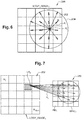
- Figure 6 represents part of an operation of determining a weight value.
- Figure 7 illustrates the determination of the weights d i , linked to the spatial proximity of the sub-block R i to the pixel LP q .
- Figure 6 represents an image LOGY_IMAGE f 200, divided into 25 sub-blocks 202.
- the pixel LP q is included in one of the sub-blocks.
- a border 204 delimits in Figure 6 the sub-blocks that will not be used to compute the context value CTX q (outside the border 204), in other words, the pixels with a spatial proximity equal to 0, from the sub-blocks that can be used to compute the context value (inside the border 204), in other words, the pixels with a spatial proximity higher than 0.
- the circuit determines weights a j , the integer j being in the range from 0 to sb-1.
- the weight a j is linked to the affinity of the pixel PM j with the pixel LP q .
- the affinity represents the difference in intensity between the pixel LP q and the pixels PM j of the mini-image.
- the value of a j is for example in the range from 0 to 1.
- the values aff_factor and fbw are preferably the same for all the pixels of an image and preferably the same for all the images of the sequence of images.
- the values aff_factor and fbw are for example chosen by the user or are preprogrammed during the programing of the process.
- the value aff_factor is in the range from 0 to 1, and is preferably not equal to 0.
- Figure 7 represents the operation of determining a weight value a j .
- Figure 7 illustrates the determination of the weight a j , linked to the affinity of the pixel LP q with the pixel PM j .
- Figure 7 represents a mini-image MPIC f 250, divided into 25 pixels, corresponding to an image 252 LOGY_IMAGE f comprising 25 regions R b .
- the affinity a j between the pixel LP q and the pixel PM j has been computed.
- the sensor computes the values of the spatial proximity for all the sub-blocks of the image LOGY_IMAGE f . Afterwards, the device determines which sub-block have a spatial proximity different from 0 and computes the values of the affinity of the pixel with the pixels of the mini-image corresponding to those sub-blocks. Therefore, for a given pixel LP q , the device does not compute the affinity between the pixel LP q of the image LOGY_IMAGE f and the pixels of the mini-image which corresponds to sub-block having a spatial proximity equal to 0.
- CTX q ECTX q ⁇ Likelihood q + LY q ⁇ 1 ⁇ Likelihood q
- the confidence is for example in the range from 0 to 1, including 0 and 1, as the weights a i and d i are in the same range.
- the confidence Confidence q is substantially equal to 0 when the circuit considers that there is not enough information for the estimated context to be considered accurate.
- the confidence is substantially equal to 0 for the pixels situated at the border between two different objects of the scene, at which point there is generally an abrupt variation in brightness and the sum of d i *a i will be low.
- the value b q is for example equal to one of several values depending on the intensity value of the pixel LP q .
- the possible values of the value b q are for example chosen by the user or preprogrammed during the programing of the process.
- Figure 8 illustrates the bias Bias q associated with a pixel P q as a function of the intensity LY q .
- the value of the bias decreases from 1 to 0 between the value Y2 and the maximum value of the intensity LY qmax .
- the bias is used to avoid saturation of the brightest and darkest pixels. Indeed, if the intensity of the brightest pixels is increased too much, it will be difficult to distinguish detail. Similarly, if the intensity of the darkest pixels is lowered too much, it will also be difficult to distinguish detail.
- the likelihood is equal to 0 and therefore, no change is made to the pixel.
- the gain value corresponding to the pixel is then equal to 1.
- the maximum or minimum values over R, Gr, Gb, B correspond to the minimum or maximum values among the red, green, and blue channels of the pixel.
- the red, green, and blue channels can be replaced by other channels, for example in the case of hyperspectral images.
- the value s is for example chosen by the user or is preprogrammed during the programing of the process.
- the value Greyness q is equal to 1. If the variable G q is less than a second threshold, chosen by the user or preprogrammed, the value Greyness q is equal to 1 minus the value s. The second threshold is lower than or equal to, preferably lower than, the first threshold. If the variable G is in the range from the second threshold to the first threshold, preferably including the first and second thresholds, the value Greyness q is equal to the value G q .
- the greyness is equal to 0 if, for a pixel, the value of a color is above a threshold, in which case the likelihood is also 0 and no change is made to the corresponding pixel.
- Figure 9 illustrates a circuit providing an example implementation of the embodiment of Figure 1 . More precisely, Figure 9 represents the circuit 300 of the device, which implements the process of Figure 1 .
- the circuit 300 for example comprises an image sensor 302 (SENSOR).
- the image sensor 302 for example comprises a Bayer sensor.
- the image sensor 302 is configured to capture successive images.
- the image sensor 302 is able to capture images at video rates.
- the image sensor 302 is configured to capture stills.
- the image sensor 302 is preferably a video camera.
- the circuit 300 for example comprises a preprocessing circuit 304 (PREPROCESSING).
- the preprocessing circuit 304 receives, as an input, the images captured by the image sensor 302.
- the output of the preprocessing unit corresponds, in this example, to the pixels of one of the images INPUT_IMAGE.
- the circuit 300 for example comprises a circuit 306 (INTENSITY).
- the circuit 306 computes the value Y q corresponding to the pixel P q being sent by the circuit 304.
- the circuit 300 for example comprises a circuit 308 (LOG) configured to implement a logarithmic function, preferably with base 2, on the value of the intensity Y q and generate the corresponding value LY q .
- LOG logarithmic function
- the circuit 300 for example comprises a circuit 310 (MINI-IMAGE) configured to create the mini-image MPIC f from the values LY q generated by the circuit 308.
- the circuit 310 for example comprises a memory configured to store the mini-images created.
- the memory comprises a region 311a (MEM1) in which the mini-image MPIC f that is created is stored and a region 311b (MEM2) in which the mini-image MPIC f-1 created based on the previous image is stored.
- the mini-image MPIC f-1 stored in the region 311b is erased when the modification of the image INPUT_IMAGE f is completed, and the mini-image MPIC f having just been created is moved from region 311a to region 311b.
- the circuit 300 for example comprises a circuit 314 (COMPUTE) configured to compute the gain map to be applied to the image INPUT_IMAGE f in order to obtain the image OUTPUT_IMAGE f . More specifically, the circuit 314 computes the gain value GMP q corresponding to the pixel P q as described above.
- a circuit 314 (COMPUTE) configured to compute the gain map to be applied to the image INPUT_IMAGE f in order to obtain the image OUTPUT_IMAGE f . More specifically, the circuit 314 computes the gain value GMP q corresponding to the pixel P q as described above.
- the circuit 300 for example comprises a circuit 316 (MODIFICATION) configured to apply the gain map to the image INPUT_IMAGE f and more specifically, to multiply the gain value GMP q and the value of the pixel P q.
- MODIFICATION configured to apply the gain map to the image INPUT_IMAGE f and more specifically, to multiply the gain value GMP q and the value of the pixel P q.
- the circuit 300 for example comprises a circuit 318 (POSTPROCESSING) configured to implement other functions.
- the other functions may include other tone mapping processes and other processes of image processing.
- the circuit 300 for example comprises a circuit 320 (MEM), for example a memory, configured to store the output image.
- MEM circuit 320
- the output image is not stored.
- the output image is for example only displayed.
- the circuit is at least partially implemented in hardware.
- the circuit may, for example, comprise a software part.
- circuits of the circuit 300 are shared by at least two processes of image processing.
- the addition of the process of local tone mapping described herein only involves the addition of circuits 310 and 314, which is advantageous in terms of silicon area and cost, as the number of hardware blocks is limited.
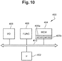
- Figure 10 illustrates a processing device providing another example of implementation of the embodiment of Figure 1 .
- This example represents an implementation entirely by way of software.
- the circuit 400 implementing the process of tone mapping described in relation with Figure 1 comprises a microprocessor, or a microcontroller 402 ( ⁇ ).
- the microprocessor implements the various operations of computation and of modification of the pixels comprised in the embodiment of Figure 1 .
- the circuit 400 also comprises at least one memory (MEM) 404.
- the memory, or memories, 404 are for example non-transitory memories configured to store at least the mini-images and the output image.
- the memory 404 comprises a region 405a (MEM1) in which the mini-image MPIC f being created is stored and a region 405b (MEM2), in which the mini-image MPIC f-1 , created based on the previous image is stored.
- the mini-image MPIC f-1 stored in the region 405b is erased when the modification of the image INPUT_IMAGE f is completed, and the mini-image MPIC f having just been created is moved from region 405a to region 405b.
- the circuit 400 comprises an input/output interface 406 (I/O).
- I/O input/output interface 406
- the interface 406 is coupled with an image sensor in a similar fashion to the image sensor described in relation with Figure 10 .
- the circuit 400 preferably comprises at least one other function 408 (FUNC).
- the various elements of the circuit 400 in particular the microprocessor 402, the memory or memories 404, the interface 406 and the functions 408, are coupled together via a bus 410.
- Various information such as the information concerning the images IMAGE f and the output image, is for example transmitted over the bus 410.
- An advantage of the embodiments described herein is that, as the image IMAGE f generated by the image sensor is not stored, the memory requirement is relatively small. Indeed, the storage of two mini-images is significantly less costly than the storage of an image IMAGE f . In a traditional regional tone mapping operation, a number of rows equal.
- Another advantage is that, as each pixel of a mini-image corresponds to an average of a bigger area, there are few differences between a mini-image and the following one. Therefore, it is possible to use a mini-image, generated using a first image, to process the following image of the successive images. Furthermore, it is possible to process the pixels with the previous mini-image, as they are caught and read by the sensor. Indeed, the mini-image is already fully available when we process the pixel. There is, therefore, no delay in this part of the processing.
- Another advantage is that the use of a logarithmic value for the creation of the mini-image allows the process not to be limited by the bit depth. It is therefore possible to use this process on images having a high dynamic and to obtain an output image with the same a high dynamic.
- the size of the mini-image can be chosen for a given sequence of successive images.
- increasing the size of the mini-image increases the size of the memory needed to store the mini-images. Being able to choose the size of the mini-image in regard with the input image allows to determine a compromise between memory space and precision depending on the application.
- Another advantage of the embodiments described herein is that, in the computations, the pixels of the images are compared with pixels of the mini-image. Therefore, there are less comparisons and less computations than if it was needed to compare with as many pixels as there are in the images of the succession of images.
- the succession of images on which the method is applied may be part of a larger group of images.
- the succession of images comprises an image out of Z images of the larger group of images, Z being an integer higher than or equal to 2.
- the method can be applied to a sequence of successive images stored in a memory.
- the method is then identical at the exception of the fact that the input images come from a storage element instead of a sensor.
Landscapes
- Physics & Mathematics (AREA)
- General Physics & Mathematics (AREA)
- Engineering & Computer Science (AREA)
- Theoretical Computer Science (AREA)
- Image Processing (AREA)
Abstract
Description
- The present disclosure relates generally to a method of image processing and to an associated circuit. More specifically, the present disclosure relates to a method of tone mapping, and to an associated circuit for tone mapping.
- High-dynamic-range imaging (HDRI) is a high dynamic range (HDR) technique used in imaging and photography to reproduce a greater dynamic range of luminosity than that possible with standard digital imaging or photographic techniques. The aim is to present a similar range of intensity to what is experienced through the human visual system.
- The human eye, through adaptation of the iris and other methods, adjusts constantly to adapt to a broad range of intensities present in the environment. The brain continuously interprets this information so that a viewer can see in a wide range of light conditions.
- Due to the limitations of printing and display contrast, the extended luminosity range of an HDR image has to be compressed to improve its visibility on Low Dynamic Range (LDR). The method of rendering an HDR image to a standard monitor or printing device is called tone mapping. This method reduces the overall contrast of an HDR image to facilitate display on devices or printouts with lower dynamic range and can be applied to produce images with preserved local contrast or exaggerated for artistic effect.
- One embodiment addresses all or some of the drawbacks of known tone mapping processes.
- One embodiment provides a tone mapping method for a succession of images implemented by an image processing device, the method including: a) the division of the images of the succession of images in a plurality of sub-blocks of first pixels; b) for a first image of the succession of images, the creation of a first mini-image comprising pixels of the first mini-image, each pixel of the first mini-image representing a corresponding sub-block of the first image, the intensity of each pixel of the first mini-image being representative of the intensity of the first pixels of the corresponding sub-block; c) the storage of the first mini-image in a memory; d) for a second image of the succession of images, the modification of the second image according to the first mini-image in order to generate an output image.
- According to an embodiment, the operation d) comprises for each first pixel of the second image: the computing of a context value, the context value depending on: the spatial proximity between the first pixel and the centers of the sub-blocks adjacent to the sub-block comprising the first pixel; and the affinity in intensity between the first pixel and the pixels of the first mini-image of the second image; the modification of the intensity of each first pixel according to the context value in order to generate the value of a pixel of the output image.
- According to an embodiment, each pixel OUTPUT_Pq of the output image is equal to OUTPUT_Pq = GMPq * Pq, where Pq represents the value of any of the channel pf the pixel, OUTPUT_Pq represents the value of the corresponding channel in the output image, and the value GMPq is a gain value dependent on the context value.
- According to an embodiment, the gain value GMPq is equal to GMPq = (LOCAL_GAINq - 1)*GLOBAL-POWER + 1, where GLOBAL_POWER is a value representing the power, or influence, of the modification by the process on the whole image and the value LOCAL_GAINq is the local contrast gain, computed based on the image LOGY_IMAGEf and the mini-image MPICf-1.
- According to an embodiment, the method further comprises storing the output image in the memory or another memory or displaying the output image.
- According to an embodiment, each sub-block comprises at least two first pixels.
- According to an embodiment, in operation b), the intensity of each pixel of the first mini-image is computed based on an average of the intensities of the first pixels of the corresponding sub-block.
- According to an embodiment, in operation b), the intensity of each pixel of the first mini-image is computed based on: the average of the intensities of the first pixels in a square centered on the corresponding sub-block, the size of the square being equal to k times the size of the sub-block, k being a number between 0 and 2, not including 0; or the average of the intensities of the first pixels in a circle centered on the corresponding sub-block, the radium of the circle being equal to k times the size of the sub-block, k being a number between 0 and 2, not including 0.
- According to an embodiment, the first mini-image used for the generation of the output image is erased from the memory after the generation of the output image.
- According to an embodiment, operation b) is applied to all the images of the succession of images.
- According to an embodiment, the modification of the first pixels is independent of the context value if: the intensity of the pixel is above a first threshold, or below a second threshold; and/or the first pixel is a color pixel and the intensity of one of the color of the first pixel is above a third threshold; and/or the accuracy of the context value is below a fourth threshold.
- According to an embodiment, the intensity of the pixels of the first mini-image is computed, in operation b), based on the logarithmic value of the intensity of the first pixels of the corresponding sub-block.
- Another embodiment provides a computer-readable non-transitory storage medium storing instructions that, when executed by a processing device, cause the previous method to be implemented.
- Another embodiment provides an image processing device for tone mapping a succession of images, each image being divided into a plurality of sub-blocks of first pixels, comprising: a circuit configured to: for a first image, create a first mini-image comprising pixels of the first mini-image, each pixel of the first mini-image representing a corresponding sub-block of the first image, the intensity of each pixel of the first mini-image being representative of the intensity of the first pixels of the corresponding sub-block; and for a second image of the succession of images, the modification of the second image according to the first mini-image in order to generate an output image, at least one memory configured to store the second image created by the circuit.
- According to an embodiment, the circuit is configured to: compute a context value, the context value depending on: the distances between the first pixel and the centers of the sub-blocks adjacent to the sub-block comprising the first pixel; and the differences in intensity between the pixel of the first mini-image corresponding to the first pixel and the adjacent pixels of the first mini-image of the second image created during the reading of the first image, and modify the intensity of each first pixel according to the context value in order to generate the intensity of a pixel of the output image.
- The foregoing features and advantages, as well as others, will be described in detail in the following description of specific embodiments given by way of illustration and not limitation with reference to the accompanying drawings, in which:
-
Figure 1 is a flow diagram illustrating an embodiment of a method of tone mapping; -
Figure 2 is a flow diagram illustrating the operations of the embodiment ofFigure 1 during cycles of the method; -
Figure 3 is a flow diagram illustrating in more detail an operation of the embodiment ofFigure 1 ; -
Figure 4 represents an operation ofFigure 3 ; -
Figure 5 is a flow diagram illustrating in more detail an operation of the embodiment ofFigure 1 ; -
Figure 6 represents part of an operation of determining a weight value; -
Figure 7 represents another part of the operation of determining a weight value; -
Figure 8 illustrates the bias of a pixel as a function of the intensity; -
Figure 9 illustrates a circuit providing an example implementation of the embodiment ofFigure 1 ; and -
Figure 10 illustrates a processing device providing another example of implementation of the embodiment ofFigure 1 . - Like features have been designated by like references in the various figures. In particular, the structural and/or functional features that are common among the various embodiments may have the same references and may dispose identical structural, dimensional and material properties.
- For the sake of clarity, only the operations and elements that are useful for an understanding of the embodiments described herein have been illustrated and described in detail.
- Unless indicated otherwise, when reference is made to two elements connected together, this signifies a direct connection without any intermediate elements other than conductors, and when reference is made to two elements linked or coupled together, this signifies that these two elements can be connected or they can be linked or coupled via one or more other elements.
- In the following disclosure, unless indicated otherwise, when reference is made to absolute positional qualifiers, such as the terms "front", "back", "top", "bottom", "left", "right", etc., or to relative positional qualifiers, such as the terms "above", "below", "higher", "lower", etc., or to qualifiers of orientation, such as "horizontal", "vertical", etc., reference is made to the orientation shown in the figures.
- Unless specified otherwise, the expressions "around", "approximately", "substantially" and "in the order of" signify within 10%, and preferably within 5%.
- For ease of reading, the following table summarizes the various references and variables used, in particular in the equations.
[Table 1] INPUT_IMAGEf The current image to which the process is applied f The index of the current image n The number of successive images Pq The current pixel in the image INPUT_IMAGEf q The index of the current pixel x The index of column of the pixel Pq in the image INPUT_IMAGEf ROW The number of rows in the image INPUT_IMAGEf y The index of row of the pixel Pq in the image INPUT_IMAGEf COL The number of columns in the image INPUT_IMAGEf Yq The brightness intensity of the pixel Pq LOGY_IMAGEf The image obtained by the application of the logarithmic function on the value of the brightness intensity of each pixel of the image INPUT_IMAGEf LPq The pixel of the image LOGY_IMAGEf corresponding to the pixel Pq LYq The intensity value of the pixel LPq and the logarithmic value of the brightness intensity of the pixel Pq. This value is coded on fbw bits MPICf The mini-image of the current image INPUT_IMAGEf PMb The pixel of the mini-image MPICf of the current image INPUT_IMAGEf LYMb The value of the pixel PMb, for example equal to an average of the values LYq of the pixel LPq b The index of the current pixel of the mini-image MPICf sb The number of pixels in the mini-image MPICf GMf The gain map of the current image INPUT_IMAGEf GMPq The gain value of the gain map corresponding to the pixel Pq of the input image INPUT_IMAGEf OUTPUT_IMAGEf The output image of the process, generated by applying the gain map to the input image OUTPUT_Pq The pixel of the output image corresponding to the pixel Pq of the input image LOCAL_GAINq The value of the local contrast gain to be applied to pixel Pq GLOBAL_POWER The value representative of the power of the global modification of the image LOCAL_POWER The value representative of the power of the local contrast enhancement of the pixels CTXq The value representing the context of the current pixel CLIP_GAIN The value representative of a threshold above which the difference between the context value and the value of the pixel is considered too high to be considered in the gain computation fbw The value is the number of bits used t code the decimal part of the pixels value LYq. The value is equal to the number of bits used to code the pixel value LYq minus the number of bits used to code the integer part of pixel value Rb The current sub-block of the image LOGY_IMAGEf, corresponding to the current pixel PMb of the mini-image Rb' The group 160 (see Figure 4 ) corresponding to the pixel PMbm The size of a sub-block h The size of a group of pixels surrounding a sub-block k A ratio, chosen by a user, between the size of a sub-block and the size of a group of pixels surrounding a sub-block ∑Rb' The cumulative sum of the values of the pixels of the group Rb' Q The number of pixels in the image LOGY_IMAGEf i The index of the sub-block corresponding to the spatial proximity di The spatial proximity between the current pixel and the sub-block Ri, for example in the range from 0 to 1. δi The distance between the current pixel and the center of the sub-block Ri Dmax An arbitrary distance, for example preprogrammed in a memory aj The affinity between the current pixel and a pixel PMj of the mini-image, for example in the range from 0 to 1. j The index of the pixel PMj corresponding to the affinity aff_factor A variable in the computation of the affinity, for example in the range from 0 to 1, zero being excluded. r The dynamic range of the image. In other words, the difference between the highest and the lowest value of the histogram of the image LOGY_IMAGEf-1 Likelihoodq The likelihood that the estimated context value is an accurate representation of the context of the pixel, for example in the range from 0 to 1. ECTXq The estimated context value Biasq A value used to avoid saturation of the brightest pixels and the darkest pixels, for example in the range from 0 to 1. Confidenceq The confidence in the estimated context, for example in the range from 0 to 1. Greynessq A parameter used to avoid increasing a color value in order to prevent color saturation, for example in the range from 0 to 1. normPq The normalized value of the pixel Pq bq A value representative of a threshold distance from the extremity of the intensity range -
Figure 1 is a flow diagram illustrating an embodiment of a method, or process, of tone mapping. More specifically,Figure 1 illustrates operations of a process of local tone mapping, meaning a process in which each pixel of an image can be modified depending on the pixels adjacent to or surrounding said pixel. Local tone mapping is to be distinguished from global tone mapping, in which the modification of each pixel is defined only by global statistics from the whole image. - The embodiment of
Figure 1 is implemented by a circuit of an electronic device, such as an image processing device. An example of a circuit implementing the process is described below with reference toFigure 9 . This process is, for example, part of a larger process of image processing implemented in the electronic device. The larger process can for example include processes of global tone mapping and other processes of local tone mapping. The larger process can also include operations of pre- and post-processing, which are for example standard processes and will not be described in detail herein. Alternatively, the process can be implemented within a sensor. - The electronic device for example comprises an image sensor configured to capture a sequence of successive images, for example the electronic device is an image sensor capable of capturing video. The image sensor is for example in a video camera.
- The process is used on a group of successive images. The group of images comprises at least two successive images. Each couple of two successive images is comprised of images of substantially the same scene at two different instants. Preferably, the two different instants are two close instants, for example less than 300 ms apart. For example, several of the successive images are taken every second. Preferably, the group of images corresponds to the various frames of a video. The frames are for example less than 50 ms apart, for example 15 ms or 30 ms apart.
- The process can be used with greyscale images, color images, or hyperspectral images. In the case of color images or hyperspectral images, the process is applied to an intensity image computed from the color or hyperspectral image. The intensity is a weighted combination of the various channels of the image. The result of the process is then applied to the initial color or hyperspectral image. Alternatively, instead of the intensity image, the process can be applied to an image computed by extracting the information of one of the channels of the color or hyperspectral image.
- The process of
Figure 1 is used on a plurality of successive input images INPUT_IMAGEf, where f is an integer going from 0 to n-1, and where n is the total number of successive images. The integer f corresponds to the position of the image in the succession of images. Thus, the image INPUT_IMAGEf directly precedes the image INPUT_IMAGEf+1. For example, the image INPUT_IMAGE4 precedes the image INPUT_IMAGE5. - Each input image INPUT_IMAGEf comprises an array of pixels Pq, the value q being the number of the pixel in the order in which the pixels are read out from an image sensor. For example, the pixels are read in each row from left to right, and from the top row to the bottom row. Thus, the value q is equal to: q=COL*y+x, COL being the number of columns in the array, y being the index of row of the pixel Pq and x being the index of column of the pixel Pq in the array. The index x goes from 0 to COL-1. The index y goes from 0 to ROW-1, ROW being the number of rows in the array.
- The images INPUT_IMAGEf are for example images created by a Bayer sensor. The images are for example usual camera images, preferably high dynamic range images (HDR images), having a bit depth for example superior or equal to 8, preferably greater than 8, for example superior or equal to 16, for example superior or equal to 24, for example superior or equal to 32. In other words, the intensity Yq of each pixel Pq is coded on at least 8 bits, for example on at least 16 bits, for example on at least 24 bits, for example on at least 32 bit. Thus, the intensity of each pixel can for example be one of at least 28 values, for example one of at least 216 values, for example one of at least 224 values, for example one of at least 232 values.
- The successive images have for example substantially the same dimensions, preferably exactly the same dimensions. Preferably, the dimensions of the images are such that each image can be divided in an array of squares.
- The process is described once for an image INPUT_IMAGEf, f being a number between 2 and n. At the start of the process, the pixel of the image INPUT_IMAGEf starts being read, and therefore the circuit implementing the process starts to receive the values of the pixels Pq of the image INPUT_IMAGEf (block 100, START INPUT_IMAGEf) . The pixels Pq have for example already been through other processes, for example through a preprocessing.
- The circuit implementing the image processing receives successively the intensity Yq corresponding to each pixel Pq of the image, pixel by pixel, in an order corresponding to the incrementation of the number q. In other words, the pixel Pq is read before the pixel Pq+1. The brightness intensity Yq of the pixel Pq is computed for each pixel is read. The brightness intensity Yq of the pixel Pq is for example computed as a linear combination of the available channels of INPUT_IMAGEf. For example, in the case of a greyscale image, the intensity is equal to the value of the pixel. For example, in the case of a color image, the intensity is a linear combination of the values of the red channel, the blue channel and the green channel.
- A
group 101 of steps of the process is performed on each pixel Pq as they are read. Thus, the various steps of thegroup 101 are all carried out on the pixel Pq, then on the pixel Pq+1, etc. The steps of thegroup 101 are described only once, in regard with a pixel Pq, the steps being reiterated for each pixel of the image INPUT_IMAGEf. - During a step represented by the block 102 (APPLY LOG TO INPUT_IMAGEf) of the
group 101, a logarithmic function, preferably with base two, is applied to the intensity of the current pixel. This operation results in a value LYq. The value LYq corresponds to the logarithmic value of the intensity of the pixel Pq. The value LYq corresponds to the intensity of a pixel LPq of an image LOGY_IMAGEf. The image LOGY_IMAGEf correspond to the image INPUT_IMAGEf after computation of the intensity and application of the logarithmic function to each pixel. The image LOGY_IMAGEf comprises the exact same number of pixels as the image INPUT_IMAGEf, each pixel Pq corresponding to a pixel LPq. - This logarithmic value is used to create a mini-image MPICf and to generate a gain map GMf, which will be used to obtain an output image. The creation of the mini-image is carried out in parallel with the generation of the gain map.
- Using the logarithmic value has the advantage of simplifying the computations. Indeed, operations of multiplication and division applied to the value Yq are equivalent to operations of addition and subtraction on the value LYq, the operations of addition and subtraction being easier and less costly to implement. Furthermore, the use of the logarithmic value increases the stability of the video where highly contrasted object of the screen appear close to each other.
- More specifically, the
group 101 comprises an operation represented by the block 104 (CREATE MINI-IMAGE MPICf). - During
operation 104, a mini-image MPICf, based on the image LOGY_IMAGEf, is created. The mini-image MPICf comprises an array of pixels PMb, where b is in the range from 0 to sb-1, sb being the number of pixels in the mini-image, the value b being the number of the pixel of the mini-image in the order in which the pixels are processed. For example, the pixels are read in each row from left to right, and from top row to bottom row. The mini-image MPICf is a reduced, or subsampled, image having a number of pixels PMb inferior to the number of pixels of the image LOGY_IMAGEf. Each pixel of the mini-image is representative of the intensity of a plurality of pixels of the corresponding image LOGY_IMAGEf. For example, each pixel of the mini-image represents the average of the plurality of pixels located in the same region of the image LOGY_IMAGEf. - The mini-image is for example a greyscale image. Each pixel PMb of the mini-image MPICf for example corresponds to an intensity LYMb. The value of the intensity LYMb of each pixel of the mini-image is for example representative of the intensity of a sub-block Rb of pixels of the image LOGY_IMAGEf. The mini-image is a subsampled version of the image LOGY_IMAGEf.
- The mini-image MPICf is of finite size and far smaller than the image INPUT_IMAGEf. The mini-image MPICf comprises for example at least 16 pixels, for example at least 576 pixels. The mini-image MPICf comprises for example between 1000 and 5000 times less pixels than the image LOGY_IMAGEf. Each pixel of the image LOGY_IMAGEf is associated with at least a pixel of the mini-image MPICf. For example, each pixel of the image LOGY_IMAGEf can be associated with only one pixel of the mini-image MPICf.
- In the case that the operations are carried out pixel by pixel, the operation represented by the
block 104 corresponds, for each pixel, to the updating of the mini-image. This step will be described in more detail in relation withFigures 3 and4 . - The step represented by the
block 104 is followed by an operation represented by a block 106 (STORE MPICf), in which the mini-image MPICf is stored in a memory. In other words, the value (s) of the pixel, or pixels, of the mini-image updated during the operation represented byblock 104 is/are stored, preferably in the same memory location as of the same pixel before having been updated. Preferably, the values of the pixels of the image INPUT_IMAGEf and of the image LOGY_IMAGEf are not stored. - In parallel with
operations operation 108 in which the gain map is created (block 108, GENERATE GAIN MAP GMf USING MPICf-1) and anoperation 110 in which the gain map is applied on the image INPUT_IMAGEf (block 110, APPLY GMf TO INPUT_IMAGEf) . - The gain map GMf is an array of gain values GMPq, each gain value GMPq corresponding to a pixel Pq of the image INPUT_IMAGEf. The values of the gain map are generated based on the image LOGY_IMAGEf and on the mini-image MPICf-1. The generation of the gain map will be described in more detail below.
- The operation represented by
block 110 generates an output image OUTPUT_IMAGEf. - More specifically, during the operation represented by
block 108, the gain value GMPq, corresponding to the current pixel Pq, is generated based on the image LOGY_IMAGEf and more specifically, based on the value of the pixel Pq, and the mini-image MPICf-1. Only one gain value GMPq is generated for each iteration of the operations of thegroup 101. - During the operation represented by
block 110, the value of each pixel Pq of the input image INPUT_IMAGEf is for example multiplied with the corresponding gain value GMPq of the gain map OUTPUT_IMAGEf. The values of the pixels OUTPUT_Pq of the output image are equal to: OUTPUT_Pq = GMPq * Pq, where Pq represents the value of the pixel, and OUTPUT_Pq represents the value of the pixel in the output image. For example, if the image is a color image or a hyperspectral image, the gain value is multiplied with the values of all the channels. The value of the gain GMPq determines the gain or attenuation to be applied on the pixel. - The gain value GMPq is preferably erased after the generation of the output pixel OUTPUT_Pq. Preferably, the values of the gain map are not stored.
- Each value of the gain map is preferably computed as follows:

- The value GLOBAL_POWER is for example the same for all the pixels of an image and preferably the same for all the images of the sequence of images. The value GLOBAL_POWER is for example chosen by the user or is preprogrammed during the programing of the process. For example, the value GLOBAL_POWER is greater than 0, for example in the range from 0 to 2, where the value 0 is preferably not included. If the value GLOBAL_POWER was equal to 0, the gains GMPq would all be equal to 1 and the output image would be identical to the input image. In other words, if the value GLOBAL_POWER was equal to 0, the method of tone mapping would have no impact on the images.
- The value LOCAL_GAINq is preferably computed as follows:

- LOCAL_POWER is a value representing the power, or influence, of the local modification by the process on the pixels,
- CTXq is a context value, representative of the context of the pixel LPq in the image LOGY_IMAGEf,
- CLIP_GAIN is the maximum acceptable difference between the logarithmic value LYq of the pixel Pq and the corresponding context value CTXq, in other words, CLIP_GAIN is threshold above which the difference between the context value and the value of the pixel is too high to be considered in the gain computation, and
- fbw is a value corresponding to the number of bits used to code the decimal part considered when using a logarithmic function on the value.
- The values LOCAL_POWER, CLIP_GAIN, and fbw are for example the same for all the pixels of an image and for example the same for all the images of the sequence of images. The values LOCAL_POWER, CLIP_GAIN, and fbw are for example chosen by the user or are preprogrammed during the programing of the process. For example, the value LOCAL_POWER, is in the range from -5 to 5. If the value LOCAL_POWER is negative, the local contrast will be diminished and if the value LOCAL_POWER is positive, the local contrast will be increased. For example, the value LOCAL_POWER, is equal to 1. For example, the value CLIP_GAIN, is higher than 0, preferably substantially equal to 2. For example, the value fbw is equal to or higher than 12.
- The computation of the value CTXq will be described in more detail in relation with
Figures 5 ,6 and 7 . The value CTXq is dependent on the spatial proximity and the affinity of the pixel with the other pixels. - As each input image is taken by the sensor at an instant sufficiently close to the instant of the previous image, the mini-images of two successive instants are similar enough that the mini-image MPICf-1 can be used in the operation of tone mapping the following image INPUT_IMAGEf taken at an instant directly after the instant in which the mini-image MPICf-1 was created. The mini-image MPICf-1 is the result of a heavy subsampling of the image LOGY_IMAGEf-1. The successive images are for example taken quickly one after another. Therefore, changes in the scene usually induce very small, almost unnoticeable, changes in the mini-images from one image to the other.
- After the mini-image MPICf-1 is used for the tone mapping of image INPUT_IMAGEf, the mini-image MPICf-1 is preferably erased from the memory. Thus, there are preferably at most two mini-images stored at any one time during the process, one being the mini-image being created and the other being the mini-image being used for the gain map.
- Preferably, other processes are applied to the output image OUTPUT_IMAGEf, for example other processes of tone mapping and post processing. The output image OUTPUT_IMAGEf is then for example displayed and/or stored by the device.
- In the case that the operations of the
group 101 are applied to the image INPUT_IMAGEf pixel by pixel, the operation of modification (bloc 110) of the pixels of the image INPUT_IMAGEf is for example applied dynamically to the pixels as they are read. - If the image INPUT_IMAGEf processed is not the last image of the sequence of successive images (branch NO,
operation 112, f = n), the value of the index f is incremented by 1 (block 114, f = f + 1). The process, starting withoperation 100 is applied on the new image INPUT_IMAGEf, corresponding to the next image of the succession of images. - In other words, if the integer f is not equal to the integer n, n being the number of successive images INPUT_IMAGEf, the process of tone mapping is applied to the new image INPUT_IMAGEf.
- If the image processed was the last image (branch YES,
operation 112, f = n), the process is finished (block 116, END) . - In order to modify an image INPUT_IMAGEf, a mini-image MPICf-1 generated based on the previous image LOGY_IMAGEf-1 is used. As such, at least one of the first images of the sequence of images is not modified, but is used to generate a mini-image.
- For example, the first images are not displayed or stored. For example, one of the first images is used to create a mini-image but is not displayed or used to generate an output image.
- The method of
Figure 1 can be implemented in software, for example by instructions stored on a computer-readable non-transitory storage medium. -
Figure 2 is a timing diagram illustrating the operation of the embodiment ofFigure 1 during three cycles of the method, in other words during processing of three successive images.Figure 2 represents the image (LOGY_IMAGE) being read (blocks Figure 1 ), the mini-image (MPIC) being created (block 104 ofFigure 1 ) and the gain map (TONE MAPPING) being applied to an image, as a function of time (t). - At an instant t0, an image IMAGEf-1 is captured by the image sensor and the values of the pixels are used to generate the values of the pixels of the image LOGY_IMAGEf-1 (block 102 of
Figure 1 ). - Between the instant t0 and an instant t1, the image INPUT_IMAGEf-1 is read and processed and the image LOGY_IMAGEf-1 is generated. In other words, the voltage generated by each pixel is received by the circuit and thus the value of the various pixels is provided to the circuit implementing the method and a logarithmic function is applied.
- Between the instant t0 and an instant t1, the mini-image MPICf-1 is also created based on the image LOGY_IMAGEf-1 (block 104 of
Figure 1 ). Furthermore, the gain map GMf-1 is generated (block 108 ofFigure 1 ), in parallel with the generation of the mini-image MPICf-1, based on the image LOGY_IMAGEf-1 and the mini-image MPICf-2 (not represented) generated previously. - At the instant t1, an image INPUT_IMAGEf is captured by the image sensor.
- Between the instant t1 and an instant t2, the image INPUT_IMAGEf is read and processed and the image LOGY_IMAGEf is generated. In other words, the voltage generated by each pixel is received by the circuit and thus the value of the various pixels are provided to the circuit implementing the method and a logarithmic function is applied.
- Between the instant t1 and an instant t2, the mini-image MPICf is also created based on the image LOGY_IMAGEf (block 104 of
Figure 1 ). Furthermore, the gain map GMf is generated (block 108 ofFigure 1 ), in parallel with the generation of the mini-image MPICf, based on the image LOGY_IMAGEf and the mini-image MPICf-1 generated previously. - At the instant t2, an image INPUT_IMAGEf+1 is captured by the image sensor.
- Between the instant t2 and an instant t3, the image INPUT_IMAGEf+1 is read and processed and the image LOGY_IMAGEf+1 is generated. In other words, the voltage generated by each pixel is received by the circuit and thus the value of the various pixels are provided to the circuit implementing the method and a logarithmic function is applied.
- Between the instant t2 and an instant t3, the mini-image MPICf+1 is also created based on the image LOGY_IMAGEf+1 (block 104 of
Figure 1 ). Furthermore, the gain map GMf+1 is generated (block 108 ofFigure 1 ), in parallel with the generation of the mini-image MPICf+1, based on the image LOGY_IMAGEf+1 and the mini-image MPICf generated previously. - At the instant t3, a following image INPUT_IMAGEf+2 is captured by the image sensor and the process continues.
- The operation of creating a mini-image based on an image LOGY_IMAGEf is preferably applied to all the images of the succession of images.
-
Figure 3 is a flow diagram illustrating in more detail theoperation 104 of the embodiment ofFigure 1 , andFigure 4 represents an image during thisoperation 104.Figures 3 and4 thus illustrate the creation of a mini-image. The value of each pixel of the mini-image is preferably an average intensity of a corresponding region in the image LOGY_IMAGEf. To compute the average intensity, the values of all the pixels of the corresponding region are summed as the pixels go through the process, and the total sum is divided by the size of the corresponding region. - We consider that
operation 104 is applied to an image LOGY_IMAGEf in order to create a mini-image MPICf, f being an integer in the range from 0 to n-1. More specifically, the operation described is applied to the pixel LPq. The operation described in relation withFigure 3 is repeated for each pixel, for example as they are provided to the circuit. - As illustrated in
Figure 4 , the image LOGY_IMAGEf is divided into an array of sub-blocks Rb, b being the index of the pixel PMb of the mini-image MPICf and the index of the corresponding sub-block Rb of the image LOGY_IMAGEf. The integer l goes from 0 to sb-1. The integer sb corresponds to the number of sub-blocks in the image LOGY_IMAGEf. The integer sb is preferably higher than 2. InFigure 4 , the image LOGY_IMAGEf is divided into twenty-five sub-blocks arranged in five rows and five columns. The index b is therefore in the range from 0 to 24 in the example ofFigure 4 . More generally, the number of rows can be different from the number of columns, as dictated by the aspect ratio of the image LOGY_IMAGEf. - Each sub-block comprises an array of
pixels 158 of the image LOGY_IMAGEf. Preferably, all the images are formed of the same number ofpixels 158. Alternatively, some of the sub-blocks, preferably at the bottom and right-hand side, can have a different number of pixels, for example comprising less pixels. Preferably, the arrays ofpixels 158 are square arrays, meaning they comprises the same number of rows as of columns of pixels. - The pixels of the mini-image are in the same order as the corresponding sub-blocks. As such, the pixel corresponding to a sub-block Rb is surrounded by the pixels corresponding to the sub-blocks surrounding the sub-block Rb.
- The division is preferably the same for all images LOGY_IMAGEf of the sequence of successive images. All images LOGY_IMAGEf are for example divided into an array of sub-blocks comprising the same number of sub-blocks, having the same number of rows of sub-blocks and the same number of columns of sub-blocks. If the pixels LPq of the image LOGY_IMAGEf correspond to the sub-block Rb of LOGY_IMAGEf, the pixel LPq of the image LOGY_IMAGEf+1 correspond to the sub-block Rb of LOGY_IMAGEf+1.
- The dimensions of the images INPUT_IMAGEf and thus of the images LOGY_IMAGEf depend on the image sensor that is used. The dimensions of the sub-blocks are preferably determined image by image, before the start of processing of each image.
- Alternatively, the dimensions of the sub-blocks are for example determined before the start of the application of the method of the first image INPUT_IMAGE1. When the image INPUT_IMAGE1 is read, pixel by pixel, meaning that the value of each pixel is provided to the circuit implementing the method, each pixel has for example already been associated with a sub-block.
- The
operation 104 described herein updates the value of some of the pixels PMb of the mini-image MPICf based on the values of agroup 160 of pixels LPq of the image LOGY_IMAGEf. Let Rb' be thegroup 160 corresponding to the pixel PMb. - The value PMb is for example based on, and in some cases equal to, an average of the values LYq of the
group 160 of pixels of the image LOGY_IMAGEf. Alternatively, the value PMb is a median value of the values LYq of thegroup 160 of pixels, the minimum value of the values LYq of thegroup 160 of pixels, the maximum value of the values LYq of thegroup 160 of pixels or any function of the values LYq of thegroup 160 of pixels. - According to an embodiment, the
group 160 of pixels includes all the pixels of the sub-block Rb and only the pixels of the sub-block Rb. - According to another embodiment, the group of
pixels 160 includes all the pixels of the sub-block Rb and some pixels of the adjacent sub-blocks. For example, the group ofpixels 160 includes all the pixels of the sub-block Rb and pixels of the adjacent sub-blocks forming a ring around the sub-block Rb. - More generally, the group of
pixels 160 may include all the pixels inside a square region centered on the sub-block. - Let m represent the size of each sub-block. In some embodiments, the sub-blocks are square, and m is the width or length of the sub-block, expressed as a number of pixels. Each sub-block is for example a square of m pixels by m pixels. The group of pixels is for example a square whose size h is given by the formula: h = floor(k * m), where floor represent a function giving the highest integer inferior to the variable of the function, and where k is a number strictly greater than 0. The number k is, preferably, equal to or greater than 1. Indeed, if k is lesser than 1, some pixels of the image LOGY_IMAGEf are not considered in the computation of the mini-image. The number k can be chosen by a user, or can be preprogrammed. For example, the values k, m and h are identical for all images of the sequence.
- At the beginning of the computation of the mini-image (
Figure 3 , block 150, START), in other words, when the first pixel of one of the images INPUT_IMAGEf is provided to the circuit implementing the method, the index q is equal to 0, corresponding to the first pixel. Furthermore, theindex 1 corresponding to the current pixel PMb is equal to 0, and the value ΣRb', corresponding to the cumulative sum of the values of the pixels of the group Rb', is equal to 0. - During the operation of
block 104, the value LYq of the pixel LPq of the group Rb' is added to the value ΣRb'. In other words, the values representative of the pixels of the mini-image are updated if the pixel on which the operation is carried out is part of thegroup 160 corresponding to these pixels of the mini-image. The process is described for a single pixel LPq. The process is reiterated for each pixel during the process of thegroup 101 ofFigure 1 . - More precisely, the circuit determines (block 152, LPq ∈ Rb'), whether the pixel LPq is comprised in the group Rb' taken into account for the computation of the value of the pixel PMb. If it is not the case (Branch NO of block 152), the index b is incremented (block 154, b=b+1) and the operation of
block 152 is repeated until b has a value such that the pixel LPq is comprised in the group Rb'. If it is the case (Branch YES of block 152), the value ΣRb' is updated (block 156, ΣRb' = ΣRb' + LYq). More precisely, the value LYq of the pixel LPq is added to the current value of ΣRb' . - The circuit then determines (block 157, b = sb-1) if this group Rb' is the last group of the image, and thus if the circuit has determined, for all the groups Rb', whether or not the pixel LPq belongs to the group. If it is not the case (Branch NO, block 157), the value b is incremented (block 154) and the process goes back to the step of
block 152. If it is the case (Branch YES, block 157), the operation is finished (block 159, END). The value ΣRb' is for example stored. The remaining operations of the method ofFigure 1 are then for example carried out. - Alternatively, one or several additional operations can be carried out on the value ΣRb' in order to obtain the value of the pixel PMb. For example, the value ΣRb' can be divided by a value, for example by h2, in order to generate an average value.
- Alternatively, the operation of
block 156, corresponding to the updating of a value used to determine the value of the pixel PMb can be a different operation. For example, the updated value corresponds to a minimum or maximum value between the value LYq and the current value of the pixel of the mini-image MPICf. - According to an embodiment, the process comprises a step during which the circuit compares the value LYq of the current pixel with a stored value, the stored value being the minimum value of the previous pixel of the image. If the stored value is higher than the value of the pixel, the value of the pixel is stored in place of the previously stored value. This value is for example used in the computation of a context value. A similar value representing the maximum value is for example generated.
- The
operation 104 represented inFigure 3 is carried out for each image LOGY_IMAGEf. Before the reiteration of the process for another image, the values of q, b and ΣRb' are reset for example to 0. - The operations of
Figure 3 are for example carried out in parallel with other operations of the process, in particular with theoperations Figure 1 . - As the number k, which is the ratio between each sub-block and the
corresponding group 160, can be greater than 1 some pixels of the image IMAGEf can be used for the computing of several of the values of the mini-image MPICf. - An advantage of using a number k greater than 1, is that it decreases the risk of artefacts, especially edge artefacts, between the various regions. It also smoothens the passage from one region of the image LOGY_IMAGEf to the other.
-
Figure 5 is a flow diagram illustrating in more detail a step of generating the context value CTXq. - This operation is described for a pixel LPq of a sub-block Rb of an image LOGY_IMAGEf.
- During an operation 190 (DETERMINING WEIGHT LINKED TO PROXIMITY), the circuit determines weights di for each sub-block Ri of the image LOGY_IMAGEf, the integer i being in the range from 0 to sb-1, sb being the number of sub-blocks in the image. Each weight di is linked to the spatial proximity of the various sub-blocks to the pixel LPq. For example, the circuit computes each weight di based on the spatial proximity of the pixel LPq to the center of the sub-block Ri.
- For example, the weight di associated to a sub-block Ri is computed as follows:

- The value δi is for example computed as follows:

- The value of di is in this example in the range from 0 to 1. If a value of di is equal to 0, which correspond to a value δi equal to, or greater than, Dmax, the associated sub-block Ri is not used in the computation, as it is not considered close enough to pixel LPq.
- The values of the weights di are for example computed for each image of the succession of images. Alternatively, as the value of each weight di is independent of the content of the images, and only depends on the size of the image and of the sub-block, the values of the weights di are for example computed once and stored in order to be used for all the images.
-
Figure 6 represents part of an operation of determining a weight value.Figure 7 illustrates the determination of the weights di, linked to the spatial proximity of the sub-block Ri to the pixel LPq. -
Figure 6 represents animage LOGY_IMAGE f 200, divided into 25sub-blocks 202. The pixel LPq is included in one of the sub-blocks. - The spatial proximity di between the pixel LPq and the centers of the
sub-blocks R i 202 has been computed. Aborder 204 delimits inFigure 6 the sub-blocks that will not be used to compute the context value CTXq (outside the border 204), in other words, the pixels with a spatial proximity equal to 0, from the sub-blocks that can be used to compute the context value (inside the border 204), in other words, the pixels with a spatial proximity higher than 0. - Referring again to
Figure 5 , during an operation 192 (DETERMINING WEIGHT LINKED TO AFFINITY), the circuit determines weights aj, the integer j being in the range from 0 to sb-1. The weight aj is linked to the affinity of the pixel PMj with the pixel LPq. For example, the closer the value of the pixel PMj to the value LYq, the higher the affinity. The affinity represents the difference in intensity between the pixel LPq and the pixels PMj of the mini-image. - For example, the weight aj can be computed as follows:

- The values aff_factor and fbw are preferably the same for all the pixels of an image and preferably the same for all the images of the sequence of images. The values aff_factor and fbw are for example chosen by the user or are preprogrammed during the programing of the process. Preferably, the value aff_factor is in the range from 0 to 1, and is preferably not equal to 0.
-
Figure 7 represents the operation of determining a weight value aj.Figure 7 illustrates the determination of the weight aj, linked to the affinity of the pixel LPq with the pixel PMj. -
Figure 7 represents amini-image MPIC f 250, divided into 25 pixels, corresponding to animage 252 LOGY_IMAGEf comprising 25 regions Rb. The affinity aj between the pixel LPq and the pixel PMj has been computed. - Preferably, for a given pixel LPq of the image LOGY_IMAGEf, the sensor computes the values of the spatial proximity for all the sub-blocks of the image LOGY_IMAGEf. Afterwards, the device determines which sub-block have a spatial proximity different from 0 and computes the values of the affinity of the pixel with the pixels of the mini-image corresponding to those sub-blocks. Therefore, for a given pixel LPq, the device does not compute the affinity between the pixel LPq of the image LOGY_IMAGEf and the pixels of the mini-image which corresponds to sub-block having a spatial proximity equal to 0.
- Referring again to
Figure 5 , during an operation 194 (COMPUTE CTXq), the circuit computes the context value CTXq. The context value is for example a weighted average. For example, the context value is computed as follows:
- The value ECTXq corresponds for example to the estimated context value and is for example computed as follows:

- The value Likelihoodq corresponds to the likelihood that the estimated context value is an accurate representation of the context of the pixel or that it is neither too extreme in intensity or colorfulness. It is for example computed as follows:

- The value Confidenceq corresponds to the confidence in the estimated context and is computed as follows:

- The confidence is for example in the range from 0 to 1, including 0 and 1, as the weights ai and di are in the same range.
- The confidence Confidenceq is substantially equal to 0 when the circuit considers that there is not enough information for the estimated context to be considered accurate. For example, the confidence is substantially equal to 0 for the pixels situated at the border between two different objects of the scene, at which point there is generally an abrupt variation in brightness and the sum of di *ai will be low.
- The value Biasq corresponds to a variable referred to as the bias, and is for example computed as follows:
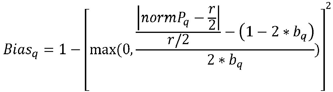
- where normPq is the normalized value of the intensity LYq of the pixel Pq. In other words, the value normPq is equal to the value
- of the pixel LPq minus the minimum value LYqmin of the previous image LOGY_IMAGEf. The number r is the range of the values of the previous image LOGY_IMAGEf, in other words, the number r is equal to the maximum value LYqmax of the intensity LYq of the image minus the minimum value LYqmin. The maximum value of the number r is equal to the bit depth minus one. The value bq is representative of the parts at the extremity of the dynamic range in which the bias is lower than 1.
- The value bq is for example equal to one of several values depending on the intensity value of the pixel LPq. The possible values of the value bq are for example chosen by the user or preprogrammed during the programing of the process.
-
Figure 8 illustrates the bias Biasq associated with a pixel Pq as a function of the intensity LYq. The value of the bias increases from 0 to 1 between the minimum intensity value LYqmin and a value Y1 of the intensity equal to Y1 = LYqmin + bq x r. The value of the bias is constant between the value Y1 and a value Y2 equal to Y2 = LYqmax - bq x r. The value of the bias decreases from 1 to 0 between the value Y2 and the maximum value of the intensity LYqmax. - The bias is used to avoid saturation of the brightest and darkest pixels. Indeed, if the intensity of the brightest pixels is increased too much, it will be difficult to distinguish detail. Similarly, if the intensity of the darkest pixels is lowered too much, it will also be difficult to distinguish detail.
- When the value of bias is equal to 0, the likelihood is equal to 0 and therefore, no change is made to the pixel. For example, the gain value corresponding to the pixel is then equal to 1.
- The value Greynessq is a variable referred to as the greyness and depends on a variable Gq, which is computed as follows:

- The value s is for example chosen by the user or is preprogrammed during the programing of the process.
- If the variable Gq is higher than a first threshold chosen by the user or preprogrammed, the value Greynessq is equal to 1. If the variable Gq is less than a second threshold, chosen by the user or preprogrammed, the value Greynessq is equal to 1 minus the value s. The second threshold is lower than or equal to, preferably lower than, the first threshold. If the variable G is in the range from the second threshold to the first threshold, preferably including the first and second thresholds, the value Greynessq is equal to the value Gq.
- Similarly to the bias, the greyness is equal to 0 if, for a pixel, the value of a color is above a threshold, in which case the likelihood is also 0 and no change is made to the corresponding pixel.
- If the images of the succession of images are in monochrome, the greyness is not computed.
- The value of the likelihood Likelihoodq is substantially equal to 0, which means that the image will not be modified or, will be modified in a negligible way, when:
- the context cannot be considered accurate, in other words when the confidence Confidenceq is substantially equal to 0; and/or
- when a modification of the value of the pixel would destroy information, for example when the intensity of the pixel above a threshold, or below a threshold or, in the case of a color pixel, if the color value of the pixel is above a threshold.
-
Figure 9 illustrates a circuit providing an example implementation of the embodiment ofFigure 1 . More precisely,Figure 9 represents thecircuit 300 of the device, which implements the process ofFigure 1 . - The
circuit 300 for example comprises an image sensor 302 (SENSOR). Theimage sensor 302 for example comprises a Bayer sensor. Theimage sensor 302 is configured to capture successive images. For example, theimage sensor 302 is able to capture images at video rates. In some embodiments, theimage sensor 302 is configured to capture stills. Theimage sensor 302 is preferably a video camera. - The
circuit 300 for example comprises a preprocessing circuit 304 (PREPROCESSING). Thepreprocessing circuit 304 receives, as an input, the images captured by theimage sensor 302. The output of the preprocessing unit corresponds, in this example, to the pixels of one of the images INPUT_IMAGE. - The
circuit 300 for example comprises a circuit 306 (INTENSITY). Thecircuit 306 computes the value Yq corresponding to the pixel Pq being sent by thecircuit 304. - The
circuit 300 for example comprises a circuit 308 (LOG) configured to implement a logarithmic function, preferably with base 2, on the value of the intensity Yq and generate the corresponding value LYq. - The
circuit 300 for example comprises a circuit 310 (MINI-IMAGE) configured to create the mini-image MPICf from the values LYq generated by thecircuit 308. Thecircuit 310 for example comprises a memory configured to store the mini-images created. Preferably, the memory comprises aregion 311a (MEM1) in which the mini-image MPICf that is created is stored and aregion 311b (MEM2) in which the mini-image MPICf-1 created based on the previous image is stored. Preferably, the mini-image MPICf-1 stored in theregion 311b is erased when the modification of the image INPUT_IMAGEf is completed, and the mini-image MPICf having just been created is moved fromregion 311a toregion 311b. - The
circuit 300 for example comprises a circuit 314 (COMPUTE) configured to compute the gain map to be applied to the image INPUT_IMAGEf in order to obtain the image OUTPUT_IMAGEf. More specifically, thecircuit 314 computes the gain value GMPq corresponding to the pixel Pq as described above. - The
circuit 300 for example comprises a circuit 316 (MODIFICATION) configured to apply the gain map to the image INPUT_IMAGEf and more specifically, to multiply the gain value GMPq and the value of the pixel Pq. - The
circuit 300 for example comprises a circuit 318 (POSTPROCESSING) configured to implement other functions. The other functions may include other tone mapping processes and other processes of image processing. - The
circuit 300 for example comprises a circuit 320 (MEM), for example a memory, configured to store the output image. Alternatively, the output image is not stored. The output image is for example only displayed. - In this example, the circuit is at least partially implemented in hardware. The circuit may, for example, comprise a software part.
- Preferably, some or all of the circuits of the
circuit 300, except for example for thecircuits circuits -
Figure 10 illustrates a processing device providing another example of implementation of the embodiment ofFigure 1 . This example represents an implementation entirely by way of software. - The
circuit 400 implementing the process of tone mapping described in relation withFigure 1 comprises a microprocessor, or a microcontroller 402 (µ). The microprocessor implements the various operations of computation and of modification of the pixels comprised in the embodiment ofFigure 1 . - The
circuit 400 also comprises at least one memory (MEM) 404. The memory, or memories, 404 are for example non-transitory memories configured to store at least the mini-images and the output image. Thememory 404 comprises aregion 405a (MEM1) in which the mini-image MPICf being created is stored and aregion 405b (MEM2), in which the mini-image MPICf-1, created based on the previous image is stored. Preferably, the mini-image MPICf-1 stored in theregion 405b is erased when the modification of the image INPUT_IMAGEf is completed, and the mini-image MPICf having just been created is moved fromregion 405a toregion 405b. - The
circuit 400 comprises an input/output interface 406 (I/O). For example, theinterface 406 is coupled with an image sensor in a similar fashion to the image sensor described in relation withFigure 10 . - The
circuit 400 preferably comprises at least one other function 408 (FUNC). - The various elements of the
circuit 400, in particular themicroprocessor 402, the memory ormemories 404, theinterface 406 and thefunctions 408, are coupled together via abus 410. Various information, such as the information concerning the images IMAGEf and the output image, is for example transmitted over thebus 410. - An advantage of the embodiments described herein is that, as the image IMAGEf generated by the image sensor is not stored, the memory requirement is relatively small. Indeed, the storage of two mini-images is significantly less costly than the storage of an image IMAGEf. In a traditional regional tone mapping operation, a number of rows equal.
- Another advantage is that, as each pixel of a mini-image corresponds to an average of a bigger area, there are few differences between a mini-image and the following one. Therefore, it is possible to use a mini-image, generated using a first image, to process the following image of the successive images. Furthermore, it is possible to process the pixels with the previous mini-image, as they are caught and read by the sensor. Indeed, the mini-image is already fully available when we process the pixel. There is, therefore, no delay in this part of the processing.
- Another advantage is that the use of a logarithmic value for the creation of the mini-image allows the process not to be limited by the bit depth. It is therefore possible to use this process on images having a high dynamic and to obtain an output image with the same a high dynamic.
- Another advantage of the embodiments described herein is that the size of the mini-image can be chosen for a given sequence of successive images. The bigger the mini-image, the more precise the tone mapping. However, increasing the size of the mini-image increases the size of the memory needed to store the mini-images. Being able to choose the size of the mini-image in regard with the input image allows to determine a compromise between memory space and precision depending on the application.
- Another advantage of the embodiments described herein is that, in the computations, the pixels of the images are compared with pixels of the mini-image. Therefore, there are less comparisons and less computations than if it was needed to compare with as many pixels as there are in the images of the succession of images.
- Various embodiments and variants have been described. Those skilled in the art will understand that certain features of these embodiments can be combined and other variants will readily occur to those skilled in the art. In particular, the succession of images on which the method is applied may be part of a larger group of images. For example, the succession of images comprises an image out of Z images of the larger group of images, Z being an integer higher than or equal to 2.
- Alternatively, the method can be applied to a sequence of successive images stored in a memory. The method is then identical at the exception of the fact that the input images come from a storage element instead of a sensor.
- Finally, the practical implementation of the embodiments and variants described herein is within the capabilities of those skilled in the art based on the functional description provided hereinabove.
Claims (15)
- A tone mapping method for a succession of images (INPUT_IMAGEf) implemented by an image processing device, the method including:a) the division of the images (INPUT_IMAGEf) of the succession of images in a plurality of sub-blocks (Rb) of first pixels (Pq);b) for a first image (INPUT_IMAGEf) of the succession of images, the creation of a first mini-image (MPICf) comprising pixels of the first mini-image, each pixel of the first mini-image representing a corresponding sub-block (Rb) of the first image, the intensity (PMb) of each pixel of the first mini-image being representative of the intensity of the first pixels of the corresponding sub-block;c) the storage of the first mini-image (MPICf) in a memory;d) for a second image (IMAGEf+1) of the succession of images, the modification of the second image according to the first mini-image (MPICf) in order to generate an output image.
- The method of claim 1, wherein the operation d) comprises for each first pixel (Pq) of the second image (IMAGEf+1):o the computing of a context value (CTXq), the context value depending on:▪ the spatial proximity (dj) between the first pixel and the centers of the sub-blocks adjacent (160) to the sub-block (Rj) comprising the first pixel; and▪ the affinity (ai) in intensity between the first pixel and the pixels of the first mini-image of the second image;∘ the modification of the intensity of each first pixel (Pq) according to the context value (CTXq) in order to generate the value of a pixel (Pq out) of the output image.
- The method of claim 2, in which each pixel OUTPUT_Pq of the output image is equal to OUTPUT_Pq = GMPq * Pq, where Pq represents the value of any of the channel of the pixel, OUTPUT_Pq represents the value of the corresponding channel in the output image, and the value GMPq is a gain value dependent on the context value (CTXq).
- The method of claim 3, in which the gain value GMPq is equal to GMPq = (LOCAL_GAINq - 1)*GLOBAL_POWER + 1, where GLOBAL_POWER is a value representing the power, or influence, of the modification by the process on the whole image and the value LOCAL_GAINq is the local contrast gain, computed based on the image LOGY_IMAGEf and the mini-image MPICf-1.
- The method of any of claims 1 to 4, further comprising storing the output image in the memory or another memory (320) or displaying the output image.
- The method of any of claims 1 to 5, in which each sub-block comprises at least two first pixels.
- The method of any of claims 1 to 6, in which, in operation b), the intensity of each pixel of the first mini-image is computed based on an average of the intensities of the first pixels of the corresponding sub-block.
- The method of any of claims 1 to 7, in which, in operation b), the intensity of each pixel of the first mini-image is computed based on:the average of the intensities of the first pixels in a square centered on the corresponding sub-block, the size of the square being equal to k times the size of the sub-block, k being a number between 0 and 2, not including 0; orthe average of the intensities of the first pixels in a circle centered on the corresponding sub-block, the radium of the circle being equal to k times the size of the sub-block, k being a number between 0 and 2, not including 0.
- The method of any of claims 1 to 8, in which the first mini-image used for the generation of the output image is erased from the memory after the generation of the output image.
- The method of any of claims 1 to 9, in which operation b) is applied to all the images (INPUT_IMAGEf) of the succession of images.
- The method of any of claims 1 to 10, in which the modification of the first pixels is independent of the context value if:• the intensity of the pixel is above a first threshold, or below a second threshold; and/or• the first pixel is a color pixel and the intensity of one of the color of the first pixel is above a third threshold; and/or• the accuracy of the context value is below a fourth threshold.
- The method of any of claims 1 to 11, wherein the intensity of the pixels of the first mini-image is computed, in operation b), based on the logarithmic value (LYq) of the intensity (Yq) of the first pixels (Pq) of the corresponding sub-block.
- A computer-readable non-transitory storage medium storing instructions that, when executed by a processing device, cause the method of any of claims 1 to 12 to be implemented.
- Image processing device for tone mapping a succession of images, each image being divided into a plurality of sub-blocks of first pixels, comprising:• a circuit (300, 400) configured to:∘ for a first image (IMAGEf), create a first mini-image (MPICf) comprising pixels of the first mini-image, each pixel of the first mini-image representing a corresponding sub-block (Ri) of the first image, the intensity of each pixel of the first mini-image being representative of the intensity of the first pixels of the corresponding sub-block; and∘ for a second image of the succession of images, the modification of the second image according to the first mini-image in order to generate an output image,• at least one memory (310) configured to store the second image created by the circuit.
- The device of claim 14, in which the circuit is configured to:∘ compute a context value, the context value depending on:▪ the distances (di) between the first pixel and the centers of the sub-blocks adjacent to the sub-block comprising the first pixel; and▪ the differences (ai) in intensity between the pixel of the first mini-image corresponding to the first pixel and the adjacent pixels of the first mini-image of the second image created during the reading of the first image, and∘ modify the intensity of each first pixel according to the context value in order to generate the intensity of a pixel of the output image.
Priority Applications (1)
| Application Number | Priority Date | Filing Date | Title |
|---|---|---|---|
| US17/168,106 US11756172B2 (en) | 2020-02-25 | 2021-02-04 | Local tone mapping for HDR video |
Applications Claiming Priority (1)
| Application Number | Priority Date | Filing Date | Title |
|---|---|---|---|
| EP20305180.0A EP3872749A1 (en) | 2020-02-25 | 2020-02-25 | Local tone mapping for hdr video |
Publications (2)
| Publication Number | Publication Date |
|---|---|
| EP3872750A1 true EP3872750A1 (en) | 2021-09-01 |
| EP3872750B1 EP3872750B1 (en) | 2025-06-25 |
Family
ID=69784369
Family Applications (2)
| Application Number | Title | Priority Date | Filing Date |
|---|---|---|---|
| EP20305180.0A Withdrawn EP3872749A1 (en) | 2020-02-25 | 2020-02-25 | Local tone mapping for hdr video |
| EP21152878.1A Active EP3872750B1 (en) | 2020-02-25 | 2021-01-22 | Local tone mapping for hdr video |
Family Applications Before (1)
| Application Number | Title | Priority Date | Filing Date |
|---|---|---|---|
| EP20305180.0A Withdrawn EP3872749A1 (en) | 2020-02-25 | 2020-02-25 | Local tone mapping for hdr video |
Country Status (2)
| Country | Link |
|---|---|
| US (1) | US11756172B2 (en) |
| EP (2) | EP3872749A1 (en) |
Families Citing this family (1)
| Publication number | Priority date | Publication date | Assignee | Title |
|---|---|---|---|---|
| KR102710388B1 (en) * | 2020-05-18 | 2024-09-27 | 에스케이하이닉스 주식회사 | Local tone mapping circuit, image sensing device and operation method thereof |
Citations (2)
| Publication number | Priority date | Publication date | Assignee | Title |
|---|---|---|---|---|
| US20070269132A1 (en) * | 2006-05-17 | 2007-11-22 | Xerox Corporation | Histogram adjustment for high dynamic range image mapping |
| US20150071537A1 (en) * | 2013-09-10 | 2015-03-12 | Apple Inc. | Image Tone Adjustment using Local Tone Curve Computation |
Family Cites Families (8)
| Publication number | Priority date | Publication date | Assignee | Title |
|---|---|---|---|---|
| US9437171B2 (en) | 2012-12-05 | 2016-09-06 | Texas Instruments Incorporated | Local tone mapping for high dynamic range images |
| JP6414386B2 (en) * | 2014-03-20 | 2018-10-31 | 株式会社島津製作所 | Image processing apparatus and image processing program |
| MX359721B (en) * | 2015-01-19 | 2018-10-08 | Dolby Laboratories Licensing Corp | Display management for high dynamic range video. |
| US11276369B2 (en) * | 2017-09-08 | 2022-03-15 | Apple Inc. | Electronic display burn-in detection and mitigation |
| DE102017218072A1 (en) * | 2017-10-11 | 2019-04-11 | Robert Bosch Gmbh | Method for taking a picture |
| CN108053381B (en) * | 2017-12-22 | 2022-04-22 | 深圳创维-Rgb电子有限公司 | Dynamic tone mapping method, mobile terminal and computer-readable storage medium |
| FR3083633B1 (en) * | 2018-07-05 | 2020-05-29 | Thales | METHOD AND DEVICE FOR DISPLAYING HIGH DYNAMIC SONAR OR RADAR DATA |
| CN109064427A (en) * | 2018-08-01 | 2018-12-21 | 京东方科技集团股份有限公司 | Enhance the method, apparatus, display equipment and storage medium of picture contrast |
-
2020
- 2020-02-25 EP EP20305180.0A patent/EP3872749A1/en not_active Withdrawn
-
2021
- 2021-01-22 EP EP21152878.1A patent/EP3872750B1/en active Active
- 2021-02-04 US US17/168,106 patent/US11756172B2/en active Active
Patent Citations (2)
| Publication number | Priority date | Publication date | Assignee | Title |
|---|---|---|---|---|
| US20070269132A1 (en) * | 2006-05-17 | 2007-11-22 | Xerox Corporation | Histogram adjustment for high dynamic range image mapping |
| US20150071537A1 (en) * | 2013-09-10 | 2015-03-12 | Apple Inc. | Image Tone Adjustment using Local Tone Curve Computation |
Also Published As
| Publication number | Publication date |
|---|---|
| US20210264579A1 (en) | 2021-08-26 |
| EP3872749A1 (en) | 2021-09-01 |
| EP3872750B1 (en) | 2025-06-25 |
| US11756172B2 (en) | 2023-09-12 |
Similar Documents
| Publication | Publication Date | Title |
|---|---|---|
| US7889921B2 (en) | Noise reduced color image using panchromatic image | |
| US7844127B2 (en) | Edge mapping using panchromatic pixels | |
| US8314847B2 (en) | Automatic tone mapping curve generation based on dynamically stretched image histogram distribution | |
| EP1789922B1 (en) | Apparatus and method for processing images | |
| US8594451B2 (en) | Edge mapping incorporating panchromatic pixels | |
| RU2397542C2 (en) | Method and device for creating images with high dynamic range from multiple exposures | |
| US8284271B2 (en) | Chroma noise reduction for cameras | |
| CN108734676A (en) | Image processing method and device, electronic equipment, computer readable storage medium | |
| US12039767B2 (en) | Subject detection method and apparatus, electronic device, and computer-readable storage medium | |
| CN108322651B (en) | Photographing method and device, electronic equipment and computer readable storage medium | |
| US7652717B2 (en) | White balance correction in digital camera images | |
| CN107945106B (en) | Image processing method, apparatus, electronic device, and computer-readable storage medium | |
| CN108616700B (en) | Image processing method and device, electronic equipment and computer readable storage medium | |
| JP6786273B2 (en) | Image processing equipment, image processing methods, and programs | |
| JPH07120409B2 (en) | Method for automatically adjusting brightness and contrast and image capture system | |
| WO2008102296A2 (en) | Method for enhancing the depth sensation of an image | |
| CN113068011B (en) | Image sensor, image processing method and system | |
| EP3872750B1 (en) | Local tone mapping for hdr video | |
| Li et al. | A color correction method based on incremental multilevel iterative histogram matching | |
| CN110996015A (en) | Spatial multiple exposure | |
| JP4290965B2 (en) | How to improve the quality of digital images | |
| JP2005130486A (en) | Video signal processing device | |
| CN108600631A (en) | Image processing method, image processing device, computer-readable storage medium and electronic equipment | |
| KR101005625B1 (en) | Color correction method according to image brightness change using camera color characteristic curve | |
| Van Vo et al. | High dynamic range video synthesis using superpixel-based illuminance-invariant motion estimation |
Legal Events
| Date | Code | Title | Description |
|---|---|---|---|
| PUAI | Public reference made under article 153(3) epc to a published international application that has entered the european phase |
Free format text: ORIGINAL CODE: 0009012 |
|
| STAA | Information on the status of an ep patent application or granted ep patent |
Free format text: STATUS: REQUEST FOR EXAMINATION WAS MADE |
|
| 17P | Request for examination filed |
Effective date: 20210122 |
|
| AK | Designated contracting states |
Kind code of ref document: A1 Designated state(s): AL AT BE BG CH CY CZ DE DK EE ES FI FR GB GR HR HU IE IS IT LI LT LU LV MC MK MT NL NO PL PT RO RS SE SI SK SM TR |
|
| STAA | Information on the status of an ep patent application or granted ep patent |
Free format text: STATUS: EXAMINATION IS IN PROGRESS |
|
| 17Q | First examination report despatched |
Effective date: 20230324 |
|
| RAP3 | Party data changed (applicant data changed or rights of an application transferred) |
Owner name: STMICROELECTRONICS FRANCE Owner name: STMICROELECTRONICS (RESEARCH & DEVELOPMENT)LIMITED |
|
| REG | Reference to a national code |
Ref country code: DE Ref legal event code: R079 Free format text: PREVIOUS MAIN CLASS: G06T0005000000 Ipc: G06T0005940000 Ref document number: 602021032661 Country of ref document: DE |
|
| GRAP | Despatch of communication of intention to grant a patent |
Free format text: ORIGINAL CODE: EPIDOSNIGR1 |
|
| STAA | Information on the status of an ep patent application or granted ep patent |
Free format text: STATUS: GRANT OF PATENT IS INTENDED |
|
| RIC1 | Information provided on ipc code assigned before grant |
Ipc: G06T 5/94 20240101AFI20250123BHEP |
|
| INTG | Intention to grant announced |
Effective date: 20250204 |
|
| RIN1 | Information on inventor provided before grant (corrected) |
Inventor name: STEWART, BRIAN Inventor name: GRESSET, HELOISE |
|
| GRAJ | Information related to disapproval of communication of intention to grant by the applicant or resumption of examination proceedings by the epo deleted |
Free format text: ORIGINAL CODE: EPIDOSDIGR1 |
|
| STAA | Information on the status of an ep patent application or granted ep patent |
Free format text: STATUS: EXAMINATION IS IN PROGRESS |
|
| GRAP | Despatch of communication of intention to grant a patent |
Free format text: ORIGINAL CODE: EPIDOSNIGR1 |
|
| STAA | Information on the status of an ep patent application or granted ep patent |
Free format text: STATUS: GRANT OF PATENT IS INTENDED |
|
| INTC | Intention to grant announced (deleted) | ||
| INTG | Intention to grant announced |
Effective date: 20250326 |
|
| GRAS | Grant fee paid |
Free format text: ORIGINAL CODE: EPIDOSNIGR3 |
|
| GRAA | (expected) grant |
Free format text: ORIGINAL CODE: 0009210 |
|
| STAA | Information on the status of an ep patent application or granted ep patent |
Free format text: STATUS: THE PATENT HAS BEEN GRANTED |
|
| AK | Designated contracting states |
Kind code of ref document: B1 Designated state(s): AL AT BE BG CH CY CZ DE DK EE ES FI FR GB GR HR HU IE IS IT LI LT LU LV MC MK MT NL NO PL PT RO RS SE SI SK SM TR |
|
| REG | Reference to a national code |
Ref country code: GB Ref legal event code: FG4D |
|
| REG | Reference to a national code |
Ref country code: CH Ref legal event code: EP |
|
| REG | Reference to a national code |
Ref country code: DE Ref legal event code: R096 Ref document number: 602021032661 Country of ref document: DE |
|
| REG | Reference to a national code |
Ref country code: CH Ref legal event code: EP |
|
| REG | Reference to a national code |
Ref country code: IE Ref legal event code: FG4D |
|
| PG25 | Lapsed in a contracting state [announced via postgrant information from national office to epo] |
Ref country code: FI Free format text: LAPSE BECAUSE OF FAILURE TO SUBMIT A TRANSLATION OF THE DESCRIPTION OR TO PAY THE FEE WITHIN THE PRESCRIBED TIME-LIMIT Effective date: 20250625 |
|
| REG | Reference to a national code |
Ref country code: LT Ref legal event code: MG9D |
|
| PG25 | Lapsed in a contracting state [announced via postgrant information from national office to epo] |
Ref country code: NO Free format text: LAPSE BECAUSE OF FAILURE TO SUBMIT A TRANSLATION OF THE DESCRIPTION OR TO PAY THE FEE WITHIN THE PRESCRIBED TIME-LIMIT Effective date: 20250925 Ref country code: GR Free format text: LAPSE BECAUSE OF FAILURE TO SUBMIT A TRANSLATION OF THE DESCRIPTION OR TO PAY THE FEE WITHIN THE PRESCRIBED TIME-LIMIT Effective date: 20250926 |
|
| PG25 | Lapsed in a contracting state [announced via postgrant information from national office to epo] |
Ref country code: BG Free format text: LAPSE BECAUSE OF FAILURE TO SUBMIT A TRANSLATION OF THE DESCRIPTION OR TO PAY THE FEE WITHIN THE PRESCRIBED TIME-LIMIT Effective date: 20250625 |
|
| PG25 | Lapsed in a contracting state [announced via postgrant information from national office to epo] |
Ref country code: HR Free format text: LAPSE BECAUSE OF FAILURE TO SUBMIT A TRANSLATION OF THE DESCRIPTION OR TO PAY THE FEE WITHIN THE PRESCRIBED TIME-LIMIT Effective date: 20250625 |
|
| PG25 | Lapsed in a contracting state [announced via postgrant information from national office to epo] |
Ref country code: RS Free format text: LAPSE BECAUSE OF FAILURE TO SUBMIT A TRANSLATION OF THE DESCRIPTION OR TO PAY THE FEE WITHIN THE PRESCRIBED TIME-LIMIT Effective date: 20250925 |
|
| PG25 | Lapsed in a contracting state [announced via postgrant information from national office to epo] |
Ref country code: LV Free format text: LAPSE BECAUSE OF FAILURE TO SUBMIT A TRANSLATION OF THE DESCRIPTION OR TO PAY THE FEE WITHIN THE PRESCRIBED TIME-LIMIT Effective date: 20250625 |
|
| REG | Reference to a national code |
Ref country code: NL Ref legal event code: MP Effective date: 20250625 |
|
| PG25 | Lapsed in a contracting state [announced via postgrant information from national office to epo] |
Ref country code: NL Free format text: LAPSE BECAUSE OF FAILURE TO SUBMIT A TRANSLATION OF THE DESCRIPTION OR TO PAY THE FEE WITHIN THE PRESCRIBED TIME-LIMIT Effective date: 20250625 |
|
| PG25 | Lapsed in a contracting state [announced via postgrant information from national office to epo] |
Ref country code: PT Free format text: LAPSE BECAUSE OF FAILURE TO SUBMIT A TRANSLATION OF THE DESCRIPTION OR TO PAY THE FEE WITHIN THE PRESCRIBED TIME-LIMIT Effective date: 20251027 |
|
| REG | Reference to a national code |
Ref country code: AT Ref legal event code: MK05 Ref document number: 1807307 Country of ref document: AT Kind code of ref document: T Effective date: 20250625 |
|
| PG25 | Lapsed in a contracting state [announced via postgrant information from national office to epo] |
Ref country code: IS Free format text: LAPSE BECAUSE OF FAILURE TO SUBMIT A TRANSLATION OF THE DESCRIPTION OR TO PAY THE FEE WITHIN THE PRESCRIBED TIME-LIMIT Effective date: 20251025 |
|
| PG25 | Lapsed in a contracting state [announced via postgrant information from national office to epo] |
Ref country code: AT Free format text: LAPSE BECAUSE OF FAILURE TO SUBMIT A TRANSLATION OF THE DESCRIPTION OR TO PAY THE FEE WITHIN THE PRESCRIBED TIME-LIMIT Effective date: 20250625 Ref country code: SM Free format text: LAPSE BECAUSE OF FAILURE TO SUBMIT A TRANSLATION OF THE DESCRIPTION OR TO PAY THE FEE WITHIN THE PRESCRIBED TIME-LIMIT Effective date: 20250625 |
|
| PG25 | Lapsed in a contracting state [announced via postgrant information from national office to epo] |
Ref country code: CZ Free format text: LAPSE BECAUSE OF FAILURE TO SUBMIT A TRANSLATION OF THE DESCRIPTION OR TO PAY THE FEE WITHIN THE PRESCRIBED TIME-LIMIT Effective date: 20250625 |
|
| PG25 | Lapsed in a contracting state [announced via postgrant information from national office to epo] |
Ref country code: PL Free format text: LAPSE BECAUSE OF FAILURE TO SUBMIT A TRANSLATION OF THE DESCRIPTION OR TO PAY THE FEE WITHIN THE PRESCRIBED TIME-LIMIT Effective date: 20250625 |
|
| PG25 | Lapsed in a contracting state [announced via postgrant information from national office to epo] |
Ref country code: EE Free format text: LAPSE BECAUSE OF FAILURE TO SUBMIT A TRANSLATION OF THE DESCRIPTION OR TO PAY THE FEE WITHIN THE PRESCRIBED TIME-LIMIT Effective date: 20250625 |
|
| PG25 | Lapsed in a contracting state [announced via postgrant information from national office to epo] |
Ref country code: SK Free format text: LAPSE BECAUSE OF FAILURE TO SUBMIT A TRANSLATION OF THE DESCRIPTION OR TO PAY THE FEE WITHIN THE PRESCRIBED TIME-LIMIT Effective date: 20250625 |
|
| PG25 | Lapsed in a contracting state [announced via postgrant information from national office to epo] |
Ref country code: ES Free format text: LAPSE BECAUSE OF FAILURE TO SUBMIT A TRANSLATION OF THE DESCRIPTION OR TO PAY THE FEE WITHIN THE PRESCRIBED TIME-LIMIT Effective date: 20250625 |
|
| PG25 | Lapsed in a contracting state [announced via postgrant information from national office to epo] |
Ref country code: DK Free format text: LAPSE BECAUSE OF FAILURE TO SUBMIT A TRANSLATION OF THE DESCRIPTION OR TO PAY THE FEE WITHIN THE PRESCRIBED TIME-LIMIT Effective date: 20250625 |
|
| PGFP | Annual fee paid to national office [announced via postgrant information from national office to epo] |
Ref country code: DE Payment date: 20251217 Year of fee payment: 6 |
|
| PG25 | Lapsed in a contracting state [announced via postgrant information from national office to epo] |
Ref country code: IT Free format text: LAPSE BECAUSE OF FAILURE TO SUBMIT A TRANSLATION OF THE DESCRIPTION OR TO PAY THE FEE WITHIN THE PRESCRIBED TIME-LIMIT Effective date: 20250625 |
|
| PLBE | No opposition filed within time limit |
Free format text: ORIGINAL CODE: 0009261 |
|
| STAA | Information on the status of an ep patent application or granted ep patent |
Free format text: STATUS: NO OPPOSITION FILED WITHIN TIME LIMIT |
|
| REG | Reference to a national code |
Ref country code: CH Ref legal event code: L10 Free format text: ST27 STATUS EVENT CODE: U-0-0-L10-L00 (AS PROVIDED BY THE NATIONAL OFFICE) Effective date: 20260507 |